EP1482207A2 - Transmission unit for hose reel sprinklers - Google Patents
Transmission unit for hose reel sprinklers Download PDFInfo
- Publication number
- EP1482207A2 EP1482207A2 EP20040012562 EP04012562A EP1482207A2 EP 1482207 A2 EP1482207 A2 EP 1482207A2 EP 20040012562 EP20040012562 EP 20040012562 EP 04012562 A EP04012562 A EP 04012562A EP 1482207 A2 EP1482207 A2 EP 1482207A2
- Authority
- EP
- European Patent Office
- Prior art keywords
- shaft
- gear
- unit according
- pto
- driven shaft
- Prior art date
- Legal status (The legal status is an assumption and is not a legal conclusion. Google has not performed a legal analysis and makes no representation as to the accuracy of the status listed.)
- Granted
Links
Images


Classifications
-
- F—MECHANICAL ENGINEERING; LIGHTING; HEATING; WEAPONS; BLASTING
- F16—ENGINEERING ELEMENTS AND UNITS; GENERAL MEASURES FOR PRODUCING AND MAINTAINING EFFECTIVE FUNCTIONING OF MACHINES OR INSTALLATIONS; THERMAL INSULATION IN GENERAL
- F16H—GEARING
- F16H3/00—Toothed gearings for conveying rotary motion with variable gear ratio or for reversing rotary motion
- F16H3/02—Toothed gearings for conveying rotary motion with variable gear ratio or for reversing rotary motion without gears having orbital motion
- F16H3/16—Toothed gearings for conveying rotary motion with variable gear ratio or for reversing rotary motion without gears having orbital motion essentially with both gears that can be put out of gear and continuously-meshing gears that can be disengaged from their shafts
-
- F—MECHANICAL ENGINEERING; LIGHTING; HEATING; WEAPONS; BLASTING
- F16—ENGINEERING ELEMENTS AND UNITS; GENERAL MEASURES FOR PRODUCING AND MAINTAINING EFFECTIVE FUNCTIONING OF MACHINES OR INSTALLATIONS; THERMAL INSULATION IN GENERAL
- F16H—GEARING
- F16H37/00—Combinations of mechanical gearings, not provided for in groups F16H1/00 - F16H35/00
- F16H37/02—Combinations of mechanical gearings, not provided for in groups F16H1/00 - F16H35/00 comprising essentially only toothed or friction gearings
- F16H37/06—Combinations of mechanical gearings, not provided for in groups F16H1/00 - F16H35/00 comprising essentially only toothed or friction gearings with a plurality of driving or driven shafts; with arrangements for dividing torque between two or more intermediate shafts
- F16H37/065—Combinations of mechanical gearings, not provided for in groups F16H1/00 - F16H35/00 comprising essentially only toothed or friction gearings with a plurality of driving or driven shafts; with arrangements for dividing torque between two or more intermediate shafts with a plurality of driving or driven shafts
-
- F—MECHANICAL ENGINEERING; LIGHTING; HEATING; WEAPONS; BLASTING
- F16—ENGINEERING ELEMENTS AND UNITS; GENERAL MEASURES FOR PRODUCING AND MAINTAINING EFFECTIVE FUNCTIONING OF MACHINES OR INSTALLATIONS; THERMAL INSULATION IN GENERAL
- F16H—GEARING
- F16H1/00—Toothed gearings for conveying rotary motion
- F16H1/02—Toothed gearings for conveying rotary motion without gears having orbital motion
- F16H1/04—Toothed gearings for conveying rotary motion without gears having orbital motion involving only two intermeshing members
- F16H1/12—Toothed gearings for conveying rotary motion without gears having orbital motion involving only two intermeshing members with non-parallel axes
- F16H1/14—Toothed gearings for conveying rotary motion without gears having orbital motion involving only two intermeshing members with non-parallel axes comprising conical gears only
Definitions
- the present invention relates to a transmission unit for hose reel sprinklers.
- hose reel sprinklers are agricultural machines used to distribute water, fertilizer, manure, slurry or other fluids on soil.
- a hose reel sprinkler is substantially constituted by a truck that supports a reel, which can rotate about its own longitudinal axis and on which a hose made of flexible material is wound; the inlet end of the hose is associated with a supply of the fluid to be distributed and the outlet end is associated with an ejection nozzle, which is supported by a cart.
- the cart Before irrigation begins, the cart is disconnected from the truck and is towed over the ground in order to unwind the hose from it.
- the reel is associated with a transmission unit, which is adapted to turn it in order to rewind the hose unwound on the ground; rewinding is generally performed during irrigation by means of a reverse motion of the cart toward the truck.
- the transmission unit is substantially constituted by a drive, which is associated with the reel with the interposition of a unit for reducing the rotation rate with one or more speeds.
- the drive is of the turbine or hydraulic motor type, and in the first case it is actuated by means of the fluid to be distributed and is inserted along a duct in which the inlet is associated with the supply of the fluid and the outlet is associated with the inlet end of the hose; there is also a circuit for bypassing the drive, which allows to throttle the flow-rate of fluid directed toward said drive in order to adjust the power it generates.
- the reduction unit is of the type with gears and parallel axes; in particular, the input shaft, which is associated with the drive, is parallel to the output shaft, which is associated with the reel.
- the reduction unit can be provided with gear shifting elements, and one of its intermediate shafts, generally the one that transmits motion directly to the output shaft, is provided with a device for coupling to an external power take-off (so-called PTO or power take-off shaft), which draws power for example from a tractor and is used to rapidly rewind the hose that is still on the ground after interrupting the flow of fluid.
- PTO power take-off shaft
- the hose can be rewound onto the reel in a so-called slow or quick mode, depending on whether the power is generated respectively by the drive or by the PTO.
- the slow mode is the normal working condition, during which the fluid is distributed on the soil; the fast mode is used at the end of the irrigation or in case of unexpected situations in order to rewind the hose that still partially lies on the ground.
- known transmission units reduce the possibility to couple additional auxiliary user devices and force the adoption of highly complicated and articulated configurations of the circuits for feeding the fluid to be distributed, which have a plurality of connections and bends, with consequent unwanted increases in distributed and concentrated load losses.
- the braking device is generally of the belt type with a preloading spring, power absorption fluctuates over time, since it is affected by the elongation and contraction of the preloading spring; this fluctuation leads to a disadvantageously uneven operation of the turbine, whose rotation rate is not constant.
- the PTO shaft of known transmission units protrudes outside the machine body and therefore its rotation implies a safety problem.
- the reduction units of known transmission units moreover, lack so-called synchronization devices for the engagement and disengagement of the complementary gear pairs that determine the speeds of the gearbox.
- the aim of the present invention is to eliminate the above-mentioned drawbacks of known transmission units for hose reel sprinklers, by providing a transmission unit for hose reel sprinklers that is compact, having in particular a reduced axial width, and is simple, quick and easy to install and maintain.
- an object of the present invention is to provide a transmission unit for hose reel sprinklers that once installed leaves more space free for maneuvering, arranging and coupling optional auxiliary user devices, allows to facilitate transport and handling of sprinklers as a whole, allows to simplify the configuration of the circuits for supplying the fluid to be distributed, and accordingly allows to reduce load losses along it.
- Other objects of the present invention are to provide a transmission unit that allows to modify simply and with limited space occupation the direction of rotation of the output shaft, to limit dissipative power absorptions and to ensure uniform operation of the drive.
- Another object of the present invention is to improve the safety and integrity of transmission units both when they are used by drawing power from the PTO shaft for fast-mode rewinding and when they are used with slow-mode rewinding.
- further objects of the present invention are to allow to change speed in a short time and even during motion transmission, i.e., while the drive is moving, without producing mutual slippage or impacts between the transmission elements, to allow to reduce wear and damage and contain the oversizing, dimensions and weight of the various transmission elements, and to limit interventions for maintaining and/or replacing them.
- Another object of the present invention is to provide a transmission unit that is simple, relatively easy to provide in practice, safe in use, effective in operation, and has a relatively low cost.
- the present transmission unit for hose reel sprinklers comprising a box-like structure for supporting and containing an ordinary gear train, which comprises a driving shaft that is associable with a hydraulic drive of a hose reel sprinkler and a driven shaft that is associable with the reel of said sprinkler and is adapted to turn it about its longitudinal axis, characterized in that the axes of said driving shaft and of said driven shaft are mutually oblique or convergent.
- the reference numeral 1 generally designates a transmission unit for hose reel sprinklers.
- the unit 1 comprises a box-like structure 2 for supporting and containing an ordinary gear train, which comprises: a driving shaft 3, which is associable with a hydraulic drive of a hose reel sprinkler; a driven shaft 4, which is associable with the reel of the sprinkler and is adapted to turn it about its own longitudinal axis; and a plurality of intermediate shafts interposed between the driving shaft 3 and the driven shaft 4 in order to reduce gradually the rotation rate and accordingly increase the torque from one to the other.
- an ordinary gear train which comprises: a driving shaft 3, which is associable with a hydraulic drive of a hose reel sprinkler; a driven shaft 4, which is associable with the reel of the sprinkler and is adapted to turn it about its own longitudinal axis; and a plurality of intermediate shafts interposed between the driving shaft 3 and the driven shaft 4 in order to reduce gradually the rotation rate and accordingly increase the torque from one to the other.
- the hose reel sprinkler is not shown, since it is of a known type; the hydraulic drive can be constituted by a turbine in which the impeller is keyed on the driving shaft 3.
- intermediate shafts there are four intermediate shafts; starting from the driving shaft 3 and proceeding toward the driven shaft 4, they comprise in succession and in a cascade configuration a first intermediate shaft 5, a second intermediate shaft 6, a third intermediate shaft 7, and a fourth intermediate shaft 8.
- the axis 3a of the driving shaft 3 and the axis 4a of the driven shaft 4 are mutually oblique or convergent, but are not parallel, the axis 4a of the driven shaft 4 being substantially parallel to the longitudinal axis of the reel of the sprinkler.
- the axes of the four intermediate shafts 5-8 are instead substantially parallel to the axis 4a of the driven shaft 4; in particular, the axis 5a of the first intermediate shaft 5 converges with the axis 3a of the driven shaft 3, motion transmission being provided between them by means of a bevel gear pair, which comprises a first bevel gear 9 that is mounted at the end of the conducting shaft 3 and meshes with a complementary second bevel gear 10 that is keyed, on the first intermediate shaft 5.
- Motion is transmitted between the intermediate shafts 5-8 and the driven shaft 4 by way of cylindrical gear pairs.
- transmission of motion between the first intermediate shaft 5 and the second intermediate shaft 6 occurs by way of a rotation rate variation device 11 of the discontinuous gear-based type, which in the illustrated embodiment is of the four-speed type.
- variation device 11 is associated with a synchronization device 12, which is adapted to allow gradual engagement of the speeds, avoiding impacts among the various gears and therefore allowing engagement of the speeds even while the axes are rotating and under load.
- the third intermediate shaft 7 is a so-called PTO shaft, since it is provided with a shank 13 that protrudes outside the box-like structure 2 and on which there is a coupling 14 for connection to a coupling for drawing external power (power take-off), for example from a tractor.
- a braking device 15 of the belt type is fitted at the shank 13.
- a gear system 16 is mounted so that it can rotate freely on the third intermediate shaft 7 (PTO) and transmits motion from the second intermediate shaft 6 to the fourth intermediate shaft 8, the third intermediate shaft 7 (PTO) remaining motionless during slow-mode rewinding.
- the gear system 16 comprises a first gear 16a, which is fixed axially and meshes with a complementary pinion 17 formed on the previous second intermediate shaft 6, and a second gear 16b or pinion, which is mounted so that it can slide axially along the third intermediate shaft 7 (PTO) with respect to the first gear 16a and meshes with a complementary gear 18 that is keyed on the subsequent fourth intermediate shaft 8.
- PTO third intermediate shaft 7
- a first engagement and disengagement device 19 of the type with radial teeth, is formed between the first gear 16a and the second gear 16b and is respectively adapted to couple them so that they rotate monolithically and to disengage them so that they rotate freely with respect to each other.
- a second engagement and disengagement device 20 of the type with radial teeth is formed between the second gear 16b and the third intermediate shaft 7 (PTO), and is adapted respectively to rotationally couple them and allow their mutual free rotation.
- a first lever 21 actuates the sliding of the second gear 16b and accordingly the alternative engagement and disengagement of the first and second engagement and disengagement devices 19 and 20.
- a respective pinion 22 is formed on the fourth intermediate shaft 8 and meshes with a complementary gear 23 that is keyed to the driven shaft 4.
- the four-speed variation device 11 comprises four cylindrical gears 24a, 25a, 26a and 27a, which are formed or keyed on the first intermediate shaft 5 and correspond respectively to the first, second, third and fourth gears (increasing rotation rate from the first gear to the fourth gear) and are adapted to mesh with four complementary cylindrical gears 24a, 25b, 26b and 27b formed or coupled on the second intermediate shaft 6.
- a first bush 28 is mounted on the second intermediate shaft 6 so that it can rotate freely and is axially fixed, and the complementary gear 25b for the second speed is rigidly mounted thereon; the complementary first-speed gear 24b is fitted thereon so that it can rotate freely; the pairs of complementary first- and second-speed gears 24a-24b and 25a-25b are always mutually engaged.
- the synchronization device 12 comprises a second bush 29, which is fitted so that it rotates monolithically with, and slides axially along, the second intermediate shaft 6; a sleeve 30 is fitted on the second shaft 29 so that it can rotate freely and integrally supports the complementary third- and fourth-speed gears 26b and 27b; the sleeve 30 slides with respect to the second intermediate shaft 6 rigidly with the second bush 29.
- the synchronization device 12 further comprises elastic torsion means, such as a helical spring 31, which is interposed between the second bush 29 and the sleeve 30 so that the opposite ends are respectively rigidly coupled thereto, and means for stopping the relative rotation of the sleeve 30 with respect to the second bush 29, such as abutment teeth 32.
- elastic torsion means such as a helical spring 31
- centripetal radial teeth 33 adapted to engage corresponding centrifugal radial teeth 34 formed on the first bush 28 for the engagement of the second speed
- a pin 35 which is adapted to engage in a corresponding seat 36 formed in the face of the complementary gear 24b for the engagement of the first speed.
- a second lever 37 actuates the sliding of the sleeve 29 in order to allow to engage the chosen speed.
- the box-like structure 2 has a plurality of bearings 38 for rotationally supporting the various shafts, sealing devices and protection devices 39, and closure lids 40, all of which are of a conventionally known type.
- the first intermediate shaft 5 comprises an end 42, which protrudes externally from said box-like structure and on which a double auxiliary coupling is formed: one coupling for a hydraulic motor and one coupling for the access of an instrument that is suitable to force the rotation of the turbine so as to allow the exit of any solid impurities (stones or others) that have jammed inside it.
- FIGS 4 to 7 illustrate the unit 1 in various operating configurations.
- the unit 1 is in a first working configuration, in which the hose is rewound onto the reel of the sprinkler in the so-called slow mode, transmitting maximum torque to the driven shaft 4.
- the power in input to the unit 1 is drawn from the drive associated with the driving shaft 3, the speed variation device 11 is engaged in first speed (24a-24b), the first engagement and disengagement device 19 is engaged, and the second engagement and disengagement device 20 is disengaged; the power in input to the driving shaft 3 is transmitted with a gradual reduction of the rotation rate and an increase in torque to the driven shaft 4.
- the third intermediate shaft 7 (PTO) is rotationally motionless and the gear system 16 rotates freely thereon in order to transmit motion from the pinion 17 to the gear 18.
- the unit 1 is in a second working configuration, in which the hose is rewound onto the reel of the sprinkler, as in Figure 1, in the so-called slow mode but at a higher speed; the only difference with respect to the first configuration in fact is that the speed variation device 11 is engaged in third speed (26a-26b).
- the unit 1 is in a third working configuration, in which the hose is rewound onto the reel of the sprinkler in a so-called fast mode, with transmission of maximum speed to the driven shaft 4.
- the power in input to the unit 1 is taken from the external power take-off PTO on the third intermediate shaft 7.
- the first engagement and disengagement device 19 is disengaged and the driving shaft and the first two intermediate shafts 5 and 6 are therefore motionless.
- the second engagement and disengagement device 20 is instead engaged and the motion in input on the third intermediate shaft 7 (PTO) is transmitted to the driven shaft 4 with a speed reduction.
- Figure 7 illustrates an alternative embodiment of the unit 1, in which a second auxiliary bevel gear 41 is fitted on the first output shaft 5, is arranged opposite the second bevel gear 10, and allows to reverse the rotation of the shafts of the unit 1.
- the disassembly of the input shaft is facilitated, while the presence of the synchronization device allows to change speeds gradually and without interference even while the turbine is moving.
Landscapes
- Engineering & Computer Science (AREA)
- General Engineering & Computer Science (AREA)
- Mechanical Engineering (AREA)
- Storing, Repeated Paying-Out, And Re-Storing Of Elongated Articles (AREA)
- Gear Transmission (AREA)
- Details Or Accessories Of Spraying Plant Or Apparatus (AREA)
- Nozzles (AREA)
- Catching Or Destruction (AREA)
- Spray Control Apparatus (AREA)
Abstract
Description
- The present invention relates to a transmission unit for hose reel sprinklers.
- It is known that hose reel sprinklers are agricultural machines used to distribute water, fertilizer, manure, slurry or other fluids on soil.
- A hose reel sprinkler is substantially constituted by a truck that supports a reel, which can rotate about its own longitudinal axis and on which a hose made of flexible material is wound; the inlet end of the hose is associated with a supply of the fluid to be distributed and the outlet end is associated with an ejection nozzle, which is supported by a cart.
- Before irrigation begins, the cart is disconnected from the truck and is towed over the ground in order to unwind the hose from it.
- The reel is associated with a transmission unit, which is adapted to turn it in order to rewind the hose unwound on the ground; rewinding is generally performed during irrigation by means of a reverse motion of the cart toward the truck.
- The transmission unit is substantially constituted by a drive, which is associated with the reel with the interposition of a unit for reducing the rotation rate with one or more speeds.
- The drive is of the turbine or hydraulic motor type, and in the first case it is actuated by means of the fluid to be distributed and is inserted along a duct in which the inlet is associated with the supply of the fluid and the outlet is associated with the inlet end of the hose; there is also a circuit for bypassing the drive, which allows to throttle the flow-rate of fluid directed toward said drive in order to adjust the power it generates.
- The reduction unit is of the type with gears and parallel axes; in particular, the input shaft, which is associated with the drive, is parallel to the output shaft, which is associated with the reel.
- The reduction unit can be provided with gear shifting elements, and one of its intermediate shafts, generally the one that transmits motion directly to the output shaft, is provided with a device for coupling to an external power take-off (so-called PTO or power take-off shaft), which draws power for example from a tractor and is used to rapidly rewind the hose that is still on the ground after interrupting the flow of fluid.
- Therefore, the hose can be rewound onto the reel in a so-called slow or quick mode, depending on whether the power is generated respectively by the drive or by the PTO.
- The slow mode is the normal working condition, during which the fluid is distributed on the soil; the fast mode is used at the end of the irrigation or in case of unexpected situations in order to rewind the hose that still partially lies on the ground.
- These transmission units of known hose reel sprinklers are not free from drawbacks, including the fact that once they are assembled they have substantial dimensions, restrict maneuvering spaces, and hinder the transport and handling of the sprinkler as a whole, due to their significant axial width.
- Moreover, known transmission units reduce the possibility to couple additional auxiliary user devices and force the adoption of highly complicated and articulated configurations of the circuits for feeding the fluid to be distributed, which have a plurality of connections and bends, with consequent unwanted increases in distributed and concentrated load losses.
- Moreover, these drawbacks are increased if it is necessary to allow reversing of the direction of rotation of the output shaft, since it is necessary to insert an auxiliary intermediate idle shaft in the reduction unit with parallel axes.
- Another drawback of known transmission units is the fact that the PTO shaft of reduction units is turned even during so-called slow-mode rewinding, and this, in view of the fact that a braking device is generally fitted thereon, causes a disadvantageous dissipative power absorption and therefore a reduction in the torque actually available on the output shaft or, in an equivalent manner, an increase in the torque that must be generated by the drive.
- Further, since the braking device is generally of the belt type with a preloading spring, power absorption fluctuates over time, since it is affected by the elongation and contraction of the preloading spring; this fluctuation leads to a disadvantageously uneven operation of the turbine, whose rotation rate is not constant.
- The PTO shaft of known transmission units protrudes outside the machine body and therefore its rotation implies a safety problem.
- Before performing fast-mode rewinding, furthermore, it is necessary to interrupt the kinematic chain inside the reduction unit in order to avoid turning the axles upstream of the PTO shaft at speeds so high that they may cause breakage and damage; this interruption is performed manually by operators, and if it is performed incorrectly or not performed at all, damage or breakage ensues.
- Another disadvantage of known transmission units consists of the fact that their maintenance is very complicated, laborious and slow; it in fact requires operations for disassembly, assembly, opening and intervention inside the housing that contains the reduction units.
- The reduction units of known transmission units, moreover, lack so-called synchronization devices for the engagement and disengagement of the complementary gear pairs that determine the speeds of the gearbox.
- Every time it is necessary to change speed, it is therefore necessary to interrupt the motion of the drive in order to work in stopped conditions, so as to avoid damaging impacts and slippage between the teeth of the pairs of complementary gears; this method of operation therefore entails disadvantageous wastes of time.
- It is noted that this refinement is not always sufficient; even in stopped conditions, the teeth of one of the complementary gears of a pair may in fact face the teeth, instead of the spaces, of the other gear; in this case, it is necessary to temporarily restart the drive in order to try to arrange the two complementary gears in a relative configuration that allows meshing of the teeth of one gear with the spaces of the other gear without impacts or slippage; accordingly, this entails performing additional operations on the part of users and additional wastes of time.
- The impacts and slippage between the teeth of the gears further cause disadvantageous damage and wear, requiring very frequent maintenance and/or replacements of the various components and/or an over sizing of said components, with a consequent increase in the dimensions and overall weight of known transmission units.
- The aim of the present invention is to eliminate the above-mentioned drawbacks of known transmission units for hose reel sprinklers, by providing a transmission unit for hose reel sprinklers that is compact, having in particular a reduced axial width, and is simple, quick and easy to install and maintain.
- Within this aim, an object of the present invention is to provide a transmission unit for hose reel sprinklers that once installed leaves more space free for maneuvering, arranging and coupling optional auxiliary user devices, allows to facilitate transport and handling of sprinklers as a whole, allows to simplify the configuration of the circuits for supplying the fluid to be distributed, and accordingly allows to reduce load losses along it.
- Other objects of the present invention are to provide a transmission unit that allows to modify simply and with limited space occupation the direction of rotation of the output shaft, to limit dissipative power absorptions and to ensure uniform operation of the drive.
- Another object of the present invention is to improve the safety and integrity of transmission units both when they are used by drawing power from the PTO shaft for fast-mode rewinding and when they are used with slow-mode rewinding.
- Finally, further objects of the present invention are to allow to change speed in a short time and even during motion transmission, i.e., while the drive is moving, without producing mutual slippage or impacts between the transmission elements, to allow to reduce wear and damage and contain the oversizing, dimensions and weight of the various transmission elements, and to limit interventions for maintaining and/or replacing them.
- Another object of the present invention is to provide a transmission unit that is simple, relatively easy to provide in practice, safe in use, effective in operation, and has a relatively low cost.
- This aim and these and other objects that will become better apparent hereinafter are achieved by the present transmission unit for hose reel sprinklers, comprising a box-like structure for supporting and containing an ordinary gear train, which comprises a driving shaft that is associable with a hydraulic drive of a hose reel sprinkler and a driven shaft that is associable with the reel of said sprinkler and is adapted to turn it about its longitudinal axis, characterized in that the axes of said driving shaft and of said driven shaft are mutually oblique or convergent.
- Further characteristics and advantages of the present invention will become better apparent from the following detailed description of a preferred but not exclusive embodiment of a transmission unit for hose reel sprinklers, illustrated by way of non-limiting example in the accompanying drawings, wherein:
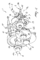
- Figure 1 is a schematic perspective view of a transmission unit for hose reel sprinklers according to the invention;
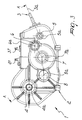
- Figure 2 is a schematic perspective cutout view of the unit of Figure 1;
- Figure 3 is a schematic front view of the unit of Figure 1;
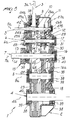
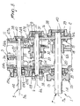
- Figure 4 is a schematic sectional view, taken along the line A-A of Figure 3, of the unit according to the invention in a first active configuration;
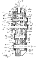
- Figure 5 is a schematic sectional view, taken along the line A-A of Figure 3, of the unit according to the invention in a second active configuration;
- Figure 6 is a schematic sectional view, taken along the line A-A of Figure 3, of the unit according to the invention in a third active configuration;
- Figure 7 is a schematic sectional view of an alternative embodiment of the unit according to the invention;
- Figure 8 is an enlarged-scale view of a detail of Figure 5.
-
- With reference to the figures, the reference numeral 1 generally designates a transmission unit for hose reel sprinklers.
- The unit 1 comprises a box-
like structure 2 for supporting and containing an ordinary gear train, which comprises: adriving shaft 3, which is associable with a hydraulic drive of a hose reel sprinkler; a drivenshaft 4, which is associable with the reel of the sprinkler and is adapted to turn it about its own longitudinal axis; and a plurality of intermediate shafts interposed between thedriving shaft 3 and the drivenshaft 4 in order to reduce gradually the rotation rate and accordingly increase the torque from one to the other. - The hose reel sprinkler is not shown, since it is of a known type; the hydraulic drive can be constituted by a turbine in which the impeller is keyed on the
driving shaft 3. - In the particular embodiment shown, there are four intermediate shafts; starting from the
driving shaft 3 and proceeding toward the drivenshaft 4, they comprise in succession and in a cascade configuration a firstintermediate shaft 5, a secondintermediate shaft 6, a thirdintermediate shaft 7, and a fourthintermediate shaft 8. - The
axis 3a of thedriving shaft 3 and theaxis 4a of the drivenshaft 4 are mutually oblique or convergent, but are not parallel, theaxis 4a of the drivenshaft 4 being substantially parallel to the longitudinal axis of the reel of the sprinkler. - The axes of the four intermediate shafts 5-8, designated by the
outlines axis 4a of the drivenshaft 4; in particular, theaxis 5a of the firstintermediate shaft 5 converges with theaxis 3a of the drivenshaft 3, motion transmission being provided between them by means of a bevel gear pair, which comprises afirst bevel gear 9 that is mounted at the end of the conductingshaft 3 and meshes with a complementarysecond bevel gear 10 that is keyed, on the firstintermediate shaft 5. - Motion is transmitted between the intermediate shafts 5-8 and the driven
shaft 4 by way of cylindrical gear pairs. - In particular, transmission of motion between the first
intermediate shaft 5 and the secondintermediate shaft 6 occurs by way of a rotationrate variation device 11 of the discontinuous gear-based type, which in the illustrated embodiment is of the four-speed type. - Advantageously, the
variation device 11 is associated with asynchronization device 12, which is adapted to allow gradual engagement of the speeds, avoiding impacts among the various gears and therefore allowing engagement of the speeds even while the axes are rotating and under load. - The third
intermediate shaft 7 is a so-called PTO shaft, since it is provided with ashank 13 that protrudes outside the box-like structure 2 and on which there is acoupling 14 for connection to a coupling for drawing external power (power take-off), for example from a tractor. - A
braking device 15 of the belt type is fitted at theshank 13. - A
gear system 16 is mounted so that it can rotate freely on the third intermediate shaft 7 (PTO) and transmits motion from the secondintermediate shaft 6 to the fourthintermediate shaft 8, the third intermediate shaft 7 (PTO) remaining motionless during slow-mode rewinding. - The
gear system 16 comprises afirst gear 16a, which is fixed axially and meshes with acomplementary pinion 17 formed on the previous secondintermediate shaft 6, and asecond gear 16b or pinion, which is mounted so that it can slide axially along the third intermediate shaft 7 (PTO) with respect to thefirst gear 16a and meshes with acomplementary gear 18 that is keyed on the subsequent fourthintermediate shaft 8. - A first engagement and
disengagement device 19, of the type with radial teeth, is formed between thefirst gear 16a and thesecond gear 16b and is respectively adapted to couple them so that they rotate monolithically and to disengage them so that they rotate freely with respect to each other. - A second engagement and
disengagement device 20 of the type with radial teeth is formed between thesecond gear 16b and the third intermediate shaft 7 (PTO), and is adapted respectively to rotationally couple them and allow their mutual free rotation. - A
first lever 21 actuates the sliding of thesecond gear 16b and accordingly the alternative engagement and disengagement of the first and second engagement anddisengagement devices - A
respective pinion 22 is formed on the fourthintermediate shaft 8 and meshes with acomplementary gear 23 that is keyed to the drivenshaft 4. - The four-
speed variation device 11 comprises fourcylindrical gears intermediate shaft 5 and correspond respectively to the first, second, third and fourth gears (increasing rotation rate from the first gear to the fourth gear) and are adapted to mesh with four complementarycylindrical gears 24a, 25b, 26b and 27b formed or coupled on the secondintermediate shaft 6. - A
first bush 28 is mounted on the secondintermediate shaft 6 so that it can rotate freely and is axially fixed, and the complementary gear 25b for the second speed is rigidly mounted thereon; the complementary first-speed gear 24b is fitted thereon so that it can rotate freely; the pairs of complementary first- and second-speed gears 24a-24b and 25a-25b are always mutually engaged. - The
synchronization device 12 comprises asecond bush 29, which is fitted so that it rotates monolithically with, and slides axially along, the secondintermediate shaft 6; asleeve 30 is fitted on thesecond shaft 29 so that it can rotate freely and integrally supports the complementary third- and fourth-speed gears 26b and 27b; thesleeve 30 slides with respect to the secondintermediate shaft 6 rigidly with thesecond bush 29. - The
synchronization device 12 further comprises elastic torsion means, such as ahelical spring 31, which is interposed between thesecond bush 29 and thesleeve 30 so that the opposite ends are respectively rigidly coupled thereto, and means for stopping the relative rotation of thesleeve 30 with respect to thesecond bush 29, such asabutment teeth 32. - On the
sleeve 30 there are also centripetalradial teeth 33, adapted to engage corresponding centrifugalradial teeth 34 formed on thefirst bush 28 for the engagement of the second speed, and apin 35, which is adapted to engage in acorresponding seat 36 formed in the face of the complementary gear 24b for the engagement of the first speed. - A
second lever 37 actuates the sliding of thesleeve 29 in order to allow to engage the chosen speed. - The box-
like structure 2 has a plurality ofbearings 38 for rotationally supporting the various shafts, sealing devices andprotection devices 39, andclosure lids 40, all of which are of a conventionally known type. - Advantageously, the first
intermediate shaft 5 comprises anend 42, which protrudes externally from said box-like structure and on which a double auxiliary coupling is formed: one coupling for a hydraulic motor and one coupling for the access of an instrument that is suitable to force the rotation of the turbine so as to allow the exit of any solid impurities (stones or others) that have jammed inside it. - Figures 4 to 7 illustrate the unit 1 in various operating configurations.
- In Figure 4, the unit 1 is in a first working configuration, in which the hose is rewound onto the reel of the sprinkler in the so-called slow mode, transmitting maximum torque to the driven
shaft 4. - In this first configuration, the power in input to the unit 1 is drawn from the drive associated with the driving
shaft 3, thespeed variation device 11 is engaged in first speed (24a-24b), the first engagement anddisengagement device 19 is engaged, and the second engagement anddisengagement device 20 is disengaged; the power in input to the drivingshaft 3 is transmitted with a gradual reduction of the rotation rate and an increase in torque to the drivenshaft 4. - In this first configuration, the third intermediate shaft 7 (PTO) is rotationally motionless and the
gear system 16 rotates freely thereon in order to transmit motion from thepinion 17 to thegear 18. - In Figure 5, the unit 1 is in a second working configuration, in which the hose is rewound onto the reel of the sprinkler, as in Figure 1, in the so-called slow mode but at a higher speed; the only difference with respect to the first configuration in fact is that the
speed variation device 11 is engaged in third speed (26a-26b). - In Figure 6, instead, the unit 1 is in a third working configuration, in which the hose is rewound onto the reel of the sprinkler in a so-called fast mode, with transmission of maximum speed to the driven
shaft 4. - In this third configuration, the power in input to the unit 1 is taken from the external power take-off PTO on the third
intermediate shaft 7. - The first engagement and
disengagement device 19 is disengaged and the driving shaft and the first twointermediate shafts - The second engagement and
disengagement device 20 is instead engaged and the motion in input on the third intermediate shaft 7 (PTO) is transmitted to the drivenshaft 4 with a speed reduction. - Figure 7 illustrates an alternative embodiment of the unit 1, in which a second
auxiliary bevel gear 41 is fitted on thefirst output shaft 5, is arranged opposite thesecond bevel gear 10, and allows to reverse the rotation of the shafts of the unit 1. - In practice it has been found that the described invention achieves the intended aim and objects.
- The possibility to arrange the drive (turbine) vertically, i.e., so that its axis is oblique or convergent with respect to the other axes, in fact allows to contain the axial dimensions of the assembly constituted by the reduction unit and the drive, to simplify the circuit for feeding the fluid to the drive and thus reduce the load losses that occur along it, to have easily available a plurality of auxiliary user devices, and to reverse the direction of motion simply.
- The possibility to engage and disengage the transmission of motion to the PTO shaft allows to improve the safety and integrity of the entire unit in operation both in the slow mode and in the fast mode; in the slow mode, the PTO shaft is assuredly stopped, thus ensuring that there are no external rotating parts, and particularly the breaking device mounted thereon is assuredly stopped, consequently reducing the dissipated power and ensuring uniform speed of the turbine; in the fast mode, disengagement of the PTO shaft from the slower preceding shafts is instead ensured.
- Moreover, the disassembly of the input shaft is facilitated, while the presence of the synchronization device allows to change speeds gradually and without interference even while the turbine is moving.
- The invention thus conceived is susceptible of numerous modifications and variations, all of which are within the scope of the appended claims.
- All the details may further be replaced with other technically equivalent ones.
- In practice, the materials used, as well as the shapes and the dimensions, may be any according the requirements without thereby abandoning the scope of the appended claims.
- The disclosures in Italian Patent Application No. MO2003A000161 from which this application claims priority are incorporated herein by reference.
- Where technical features mentioned in any claim are followed by reference signs, those reference signs have been included for the sole purpose of increasing the intelligibility of the claims and accordingly, such reference signs do not have any limiting effect on the interpretation of each element identified by way of example by such reference signs.
Claims (17)
- A transmission unit for hose reel sprinklers, comprising a box-like structure for supporting and containing an ordinary gear train, which comprises a driving shaft that is associable with a hydraulic drive of a hose reel sprinkler and a driven shaft that is associable with the reel of said sprinkler and is adapted to turn it about its longitudinal axis, characterized in that the axes of said driving shaft and of said driven shaft are mutually oblique or convergent.
- The unit according to claim 1, characterized in that said gear system comprises at least one intermediate shaft with an axis that is substantially parallel to said axis of the driven shaft.
- The unit according to claim 1, characterized in that said driven shaft is substantially parallel to the longitudinal axis of said reel.
- The unit according to one or more of the preceding claims, characterized in that said gear train is designed to reduce the rotation rate from said driving shaft to said driven shaft.
- The unit according to one or more of the preceding claims, characterized in that said gear train comprises a first said intermediate shaft whose axis substantially converges with said axis of the driving shaft, a pair of complementary bevel gears being formed between the driving shaft and said first intermediate shaft.
- The unit according to one or more of the preceding claims, characterized in that it comprises a speed variation device of the discontinuous gear-based type, said device being formed between two successive said intermediate shafts.
- The unit according to one or more of the preceding claims, characterized in that it comprises a synchronization device that is associated with said speed variation device.
- The unit according to one or more of the preceding claims, characterized in that one of said intermediate shafts is a PTO shaft.
- The unit according to claim 8, characterized in that said gear train comprises a gear that is coaxial to said PTO shaft, is associated with engagement and disengagement devices and is adapted to alternatively and selectively connect said driving shaft to said driven shaft and said PTO shaft to said driven shaft.
- The unit according to one or more of the preceding claims, characterized in that said gear train comprises a gear system for transmitting motion from said driving shaft to said driven shaft, which is mounted on said PTO shaft so that it can rotate freely.
- The unit according to one or more of the preceding claims, characterized in that said transmission gear system mounted on the PTO shaft comprises a first gear, which is fixed axially and is adapted to receive motion from said driving shaft or from one of said intermediate shafts, a second gear, which is mounted so that it can slide axially along the PTO shaft with respect to the first gear and is adapted to transmit motion to said driven shaft or to one of said intermediate shafts, a first engagement and disengagement device, which is formed between said first gear and said second gear and is respectively adapted to couple them so that they rotate monolithically and disengage them so that they rotate freely with respect to each other, and a second engagement and disengagement device, which is respectively adapted to rotationally rigidly couple and rotationally disengage with respect to each other said PTO shaft and said second gear, said first and second engagement and disengagement devices being alternatively engaged and disengaged.
- The unit according to one or more of the preceding claims, characterized in that it comprises a second said intermediate shaft, said speed variation device being formed between said first intermediate shaft and said second intermediate shaft.
- The assembly according to one or more of the preceding claims, characterized in that it comprises a third said intermediate shaft, which forms said PTO shaft.
- The unit according to one or more of the preceding claims, characterized in that it comprises a fourth said intermediate shaft.
- The unit according to one or more of the preceding claims, characterized in that said first intermediate shaft comprises an end that protrudes externally from said box-like structure and on which at least one auxiliary coupling is formed.
- The unit according to one or more of the preceding claims, characterized in that said synchronization device comprises a bush, which is mounted so that it can rotate rigidly with, and slide axially on, one of the shafts of said pair of successive intermediate shafts, and on which at least one gear of said speed variation device is mounted so that it can rotate freely, said gear being suitable to mesh with a complementary gear that is mounted so as to rotate monolithically with, and is axially fixed to, the other shaft of the pair, elastic torsion means interposed between said bush and said gear mounted thereon, and means for stopping the relative rotation of the gear with respect to the bush.
- The unit according to one or more of the preceding claims, characterized in that said gear train comprises a first said intermediate shaft in which the axis is substantially oblique with respect to said driving shaft axis.
Applications Claiming Priority (2)
| Application Number | Priority Date | Filing Date | Title |
|---|---|---|---|
| ITMO20030161 | 2003-05-30 | ||
| IT000161A ITMO20030161A1 (en) | 2003-05-30 | 2003-05-30 | TRANSMISSION GROUP FOR COIL SPRINKLERS |
Publications (3)
| Publication Number | Publication Date |
|---|---|
| EP1482207A2 true EP1482207A2 (en) | 2004-12-01 |
| EP1482207A3 EP1482207A3 (en) | 2006-06-07 |
| EP1482207B1 EP1482207B1 (en) | 2010-09-01 |
Family
ID=30012761
Family Applications (1)
| Application Number | Title | Priority Date | Filing Date |
|---|---|---|---|
| EP04012562A Active EP1482207B1 (en) | 2003-05-30 | 2004-05-27 | Transmission unit for hose reel sprinklers |
Country Status (5)
| Country | Link |
|---|---|
| EP (1) | EP1482207B1 (en) |
| AT (1) | ATE479856T1 (en) |
| DE (1) | DE602004028893D1 (en) |
| DK (1) | DK1482207T3 (en) |
| IT (1) | ITMO20030161A1 (en) |
Cited By (1)
| Publication number | Priority date | Publication date | Assignee | Title |
|---|---|---|---|---|
| ITUB20150784A1 (en) * | 2015-05-22 | 2016-11-22 | Irrimec S R L | RAIN IRRIGATION SYSTEM WITH SELF-PROPELLED DRUM. |
Families Citing this family (1)
| Publication number | Priority date | Publication date | Assignee | Title |
|---|---|---|---|---|
| CN101608683B (en) * | 2009-07-21 | 2011-05-18 | 南京高特齿轮箱制造有限公司 | Non-stop variable speed gear box for coiler with big reel or large tension |
Citations (3)
| Publication number | Priority date | Publication date | Assignee | Title |
|---|---|---|---|---|
| GB652586A (en) * | 1948-11-15 | 1951-04-25 | Donald Mayer King | Improvements in or relating to reduction gearing |
| US2940321A (en) * | 1957-07-17 | 1960-06-14 | Porsche Kg | Change-speed transmission |
| US5090268A (en) * | 1990-11-06 | 1992-02-25 | H & S Manufacturing Co., Inc. | Two speed gearbox |
-
2003
- 2003-05-30 IT IT000161A patent/ITMO20030161A1/en unknown
-
2004
- 2004-05-27 DK DK04012562.7T patent/DK1482207T3/en active
- 2004-05-27 AT AT04012562T patent/ATE479856T1/en active
- 2004-05-27 DE DE602004028893T patent/DE602004028893D1/en active Active
- 2004-05-27 EP EP04012562A patent/EP1482207B1/en active Active
Patent Citations (3)
| Publication number | Priority date | Publication date | Assignee | Title |
|---|---|---|---|---|
| GB652586A (en) * | 1948-11-15 | 1951-04-25 | Donald Mayer King | Improvements in or relating to reduction gearing |
| US2940321A (en) * | 1957-07-17 | 1960-06-14 | Porsche Kg | Change-speed transmission |
| US5090268A (en) * | 1990-11-06 | 1992-02-25 | H & S Manufacturing Co., Inc. | Two speed gearbox |
Cited By (2)
| Publication number | Priority date | Publication date | Assignee | Title |
|---|---|---|---|---|
| ITUB20150784A1 (en) * | 2015-05-22 | 2016-11-22 | Irrimec S R L | RAIN IRRIGATION SYSTEM WITH SELF-PROPELLED DRUM. |
| EP3095319A1 (en) * | 2015-05-22 | 2016-11-23 | Irrimec S.r.l. | A sprinkler irrigation plant with a self-propelling drum and a activating method |
Also Published As
| Publication number | Publication date |
|---|---|
| EP1482207A3 (en) | 2006-06-07 |
| EP1482207B1 (en) | 2010-09-01 |
| DE602004028893D1 (en) | 2010-10-14 |
| ATE479856T1 (en) | 2010-09-15 |
| ITMO20030161A1 (en) | 2004-11-30 |
| ITMO20030161A0 (en) | 2003-05-30 |
| DK1482207T3 (en) | 2010-12-20 |
Similar Documents
| Publication | Publication Date | Title |
|---|---|---|
| US20110030505A1 (en) | Hybrid Transmission | |
| EP1634758B1 (en) | Transmission unit particularly for driving the screw feeders and auxiliary user devices of mixing trucks | |
| US4286480A (en) | Speed reducer | |
| US20030037527A1 (en) | Drive arrangement for ensilage harvester discharge spout | |
| EP1482207B1 (en) | Transmission unit for hose reel sprinklers | |
| US4732330A (en) | Drive gearbox and spreader implement | |
| CA1200991A (en) | Variable drive for a harvester functional element | |
| US2930242A (en) | Crawling attachment | |
| KR20040100871A (en) | Transmission for work vehicle having pto function | |
| KR102145216B1 (en) | Driving device for cutting protion of combine | |
| KR101417631B1 (en) | Combine Harvest Moving Rotation Device | |
| US4274302A (en) | Gear reduction apparatus | |
| KR102063662B1 (en) | Transmission of Agricultural Vehicle | |
| US5535864A (en) | Transmission for a working vehicle | |
| JP2003267079A (en) | Front wheel transmission device for working vehicle | |
| US4454787A (en) | Variable drive for a harvester functional element | |
| JP2011179642A (en) | Working vehicle | |
| JP4336954B2 (en) | Transmission mechanism of traveling device | |
| RU2000963C1 (en) | Tractor power take-off reduction gear and gearbox drive | |
| KR101710753B1 (en) | Combine | |
| KR101577117B1 (en) | An planting arm for a rice planting machine | |
| DK159634B (en) | AGRICULTURAL MACHINE FOR OPERATING THE POWER SUPPLY ON A TRACTOR | |
| US2512497A (en) | Gearing control for drilling machine trucks or the like | |
| KR102292264B1 (en) | Transmission of Agricultural Vehicle | |
| KR102262737B1 (en) | Power Take-off Apparatus of Agricultural Vehicle |
Legal Events
| Date | Code | Title | Description |
|---|---|---|---|
| PUAI | Public reference made under article 153(3) epc to a published international application that has entered the european phase |
Free format text: ORIGINAL CODE: 0009012 |
|
| AK | Designated contracting states |
Kind code of ref document: A2 Designated state(s): AT BE BG CH CY CZ DE DK EE ES FI FR GB GR HU IE IT LI LU MC NL PL PT RO SE SI SK TR |
|
| AX | Request for extension of the european patent |
Extension state: AL HR LT LV MK |
|
| PUAL | Search report despatched |
Free format text: ORIGINAL CODE: 0009013 |
|
| AK | Designated contracting states |
Kind code of ref document: A3 Designated state(s): AT BE BG CH CY CZ DE DK EE ES FI FR GB GR HU IE IT LI LU MC NL PL PT RO SE SI SK TR |
|
| AX | Request for extension of the european patent |
Extension state: AL HR LT LV MK |
|
| RIC1 | Information provided on ipc code assigned before grant |
Ipc: F16H 37/06 20060101AFI20060428BHEP |
|
| 17P | Request for examination filed |
Effective date: 20061204 |
|
| AKX | Designation fees paid |
Designated state(s): AT BE BG CH CY CZ DE DK EE ES FI FR GB GR HU IE IT LI LU MC NL PL PT RO SE SI SK TR |
|
| 17Q | First examination report despatched |
Effective date: 20070425 |
|
| GRAP | Despatch of communication of intention to grant a patent |
Free format text: ORIGINAL CODE: EPIDOSNIGR1 |
|
| RAP1 | Party data changed (applicant data changed or rights of an application transferred) |
Owner name: COMER INDUSTRIES S.P.A. |
|
| GRAS | Grant fee paid |
Free format text: ORIGINAL CODE: EPIDOSNIGR3 |
|
| GRAA | (expected) grant |
Free format text: ORIGINAL CODE: 0009210 |
|
| AK | Designated contracting states |
Kind code of ref document: B1 Designated state(s): AT BE BG CH CY CZ DE DK EE ES FI FR GB GR HU IE IT LI LU MC NL PL PT RO SE SI SK TR |
|
| REG | Reference to a national code |
Ref country code: GB Ref legal event code: FG4D |
|
| REG | Reference to a national code |
Ref country code: CH Ref legal event code: EP |
|
| REG | Reference to a national code |
Ref country code: IE Ref legal event code: FG4D |
|
| REF | Corresponds to: |
Ref document number: 602004028893 Country of ref document: DE Date of ref document: 20101014 Kind code of ref document: P |
|
| REG | Reference to a national code |
Ref country code: GR Ref legal event code: EP Ref document number: 20100402169 Country of ref document: GR |
|
| REG | Reference to a national code |
Ref country code: DK Ref legal event code: T3 |
|
| REG | Reference to a national code |
Ref country code: NL Ref legal event code: VDEP Effective date: 20100901 |
|
| PG25 | Lapsed in a contracting state [announced via postgrant information from national office to epo] |
Ref country code: FI Free format text: LAPSE BECAUSE OF FAILURE TO SUBMIT A TRANSLATION OF THE DESCRIPTION OR TO PAY THE FEE WITHIN THE PRESCRIBED TIME-LIMIT Effective date: 20100901 |
|
| PG25 | Lapsed in a contracting state [announced via postgrant information from national office to epo] |
Ref country code: SI Free format text: LAPSE BECAUSE OF FAILURE TO SUBMIT A TRANSLATION OF THE DESCRIPTION OR TO PAY THE FEE WITHIN THE PRESCRIBED TIME-LIMIT Effective date: 20100901 Ref country code: PL Free format text: LAPSE BECAUSE OF FAILURE TO SUBMIT A TRANSLATION OF THE DESCRIPTION OR TO PAY THE FEE WITHIN THE PRESCRIBED TIME-LIMIT Effective date: 20100901 Ref country code: CY Free format text: LAPSE BECAUSE OF FAILURE TO SUBMIT A TRANSLATION OF THE DESCRIPTION OR TO PAY THE FEE WITHIN THE PRESCRIBED TIME-LIMIT Effective date: 20100901 |
|
| PG25 | Lapsed in a contracting state [announced via postgrant information from national office to epo] |
Ref country code: NL Free format text: LAPSE BECAUSE OF FAILURE TO SUBMIT A TRANSLATION OF THE DESCRIPTION OR TO PAY THE FEE WITHIN THE PRESCRIBED TIME-LIMIT Effective date: 20100901 Ref country code: SE Free format text: LAPSE BECAUSE OF FAILURE TO SUBMIT A TRANSLATION OF THE DESCRIPTION OR TO PAY THE FEE WITHIN THE PRESCRIBED TIME-LIMIT Effective date: 20100901 |
|
| PG25 | Lapsed in a contracting state [announced via postgrant information from national office to epo] |
Ref country code: SK Free format text: LAPSE BECAUSE OF FAILURE TO SUBMIT A TRANSLATION OF THE DESCRIPTION OR TO PAY THE FEE WITHIN THE PRESCRIBED TIME-LIMIT Effective date: 20100901 Ref country code: PT Free format text: LAPSE BECAUSE OF FAILURE TO SUBMIT A TRANSLATION OF THE DESCRIPTION OR TO PAY THE FEE WITHIN THE PRESCRIBED TIME-LIMIT Effective date: 20110103 Ref country code: RO Free format text: LAPSE BECAUSE OF FAILURE TO SUBMIT A TRANSLATION OF THE DESCRIPTION OR TO PAY THE FEE WITHIN THE PRESCRIBED TIME-LIMIT Effective date: 20100901 Ref country code: CZ Free format text: LAPSE BECAUSE OF FAILURE TO SUBMIT A TRANSLATION OF THE DESCRIPTION OR TO PAY THE FEE WITHIN THE PRESCRIBED TIME-LIMIT Effective date: 20100901 Ref country code: EE Free format text: LAPSE BECAUSE OF FAILURE TO SUBMIT A TRANSLATION OF THE DESCRIPTION OR TO PAY THE FEE WITHIN THE PRESCRIBED TIME-LIMIT Effective date: 20100901 |
|
| PG25 | Lapsed in a contracting state [announced via postgrant information from national office to epo] |
Ref country code: BE Free format text: LAPSE BECAUSE OF FAILURE TO SUBMIT A TRANSLATION OF THE DESCRIPTION OR TO PAY THE FEE WITHIN THE PRESCRIBED TIME-LIMIT Effective date: 20100901 Ref country code: ES Free format text: LAPSE BECAUSE OF FAILURE TO SUBMIT A TRANSLATION OF THE DESCRIPTION OR TO PAY THE FEE WITHIN THE PRESCRIBED TIME-LIMIT Effective date: 20101212 |
|
| PLBE | No opposition filed within time limit |
Free format text: ORIGINAL CODE: 0009261 |
|
| STAA | Information on the status of an ep patent application or granted ep patent |
Free format text: STATUS: NO OPPOSITION FILED WITHIN TIME LIMIT |
|
| 26N | No opposition filed |
Effective date: 20110606 |
|
| REG | Reference to a national code |
Ref country code: DE Ref legal event code: R097 Ref document number: 602004028893 Country of ref document: DE Effective date: 20110606 |
|
| PG25 | Lapsed in a contracting state [announced via postgrant information from national office to epo] |
Ref country code: MC Free format text: LAPSE BECAUSE OF NON-PAYMENT OF DUE FEES Effective date: 20110531 |
|
| REG | Reference to a national code |
Ref country code: CH Ref legal event code: PL |
|
| GBPC | Gb: european patent ceased through non-payment of renewal fee |
Effective date: 20110527 |
|
| PG25 | Lapsed in a contracting state [announced via postgrant information from national office to epo] |
Ref country code: CH Free format text: LAPSE BECAUSE OF NON-PAYMENT OF DUE FEES Effective date: 20110531 Ref country code: LI Free format text: LAPSE BECAUSE OF NON-PAYMENT OF DUE FEES Effective date: 20110531 |
|
| REG | Reference to a national code |
Ref country code: IE Ref legal event code: MM4A |
|
| PG25 | Lapsed in a contracting state [announced via postgrant information from national office to epo] |
Ref country code: IE Free format text: LAPSE BECAUSE OF NON-PAYMENT OF DUE FEES Effective date: 20110527 |
|
| PG25 | Lapsed in a contracting state [announced via postgrant information from national office to epo] |
Ref country code: GB Free format text: LAPSE BECAUSE OF NON-PAYMENT OF DUE FEES Effective date: 20110527 |
|
| PG25 | Lapsed in a contracting state [announced via postgrant information from national office to epo] |
Ref country code: LU Free format text: LAPSE BECAUSE OF NON-PAYMENT OF DUE FEES Effective date: 20110527 |
|
| PG25 | Lapsed in a contracting state [announced via postgrant information from national office to epo] |
Ref country code: BG Free format text: LAPSE BECAUSE OF FAILURE TO SUBMIT A TRANSLATION OF THE DESCRIPTION OR TO PAY THE FEE WITHIN THE PRESCRIBED TIME-LIMIT Effective date: 20101201 |
|
| PG25 | Lapsed in a contracting state [announced via postgrant information from national office to epo] |
Ref country code: HU Free format text: LAPSE BECAUSE OF FAILURE TO SUBMIT A TRANSLATION OF THE DESCRIPTION OR TO PAY THE FEE WITHIN THE PRESCRIBED TIME-LIMIT Effective date: 20100901 |
|
| REG | Reference to a national code |
Ref country code: FR Ref legal event code: PLFP Year of fee payment: 12 |
|
| REG | Reference to a national code |
Ref country code: FR Ref legal event code: PLFP Year of fee payment: 13 |
|
| REG | Reference to a national code |
Ref country code: FR Ref legal event code: PLFP Year of fee payment: 14 |
|
| REG | Reference to a national code |
Ref country code: FR Ref legal event code: PLFP Year of fee payment: 15 |
|
| PGFP | Annual fee paid to national office [announced via postgrant information from national office to epo] |
Ref country code: DE Payment date: 20200528 Year of fee payment: 17 Ref country code: TR Payment date: 20200522 Year of fee payment: 17 Ref country code: FR Payment date: 20200529 Year of fee payment: 17 Ref country code: DK Payment date: 20200529 Year of fee payment: 17 Ref country code: GR Payment date: 20200528 Year of fee payment: 17 |
|
| PGFP | Annual fee paid to national office [announced via postgrant information from national office to epo] |
Ref country code: IT Payment date: 20200519 Year of fee payment: 17 |
|
| PGFP | Annual fee paid to national office [announced via postgrant information from national office to epo] |
Ref country code: AT Payment date: 20200528 Year of fee payment: 17 |
|
| REG | Reference to a national code |
Ref country code: DE Ref legal event code: R119 Ref document number: 602004028893 Country of ref document: DE |
|
| REG | Reference to a national code |
Ref country code: DK Ref legal event code: EBP Effective date: 20210531 |
|
| REG | Reference to a national code |
Ref country code: AT Ref legal event code: MM01 Ref document number: 479856 Country of ref document: AT Kind code of ref document: T Effective date: 20210527 |
|
| PG25 | Lapsed in a contracting state [announced via postgrant information from national office to epo] |
Ref country code: AT Free format text: LAPSE BECAUSE OF NON-PAYMENT OF DUE FEES Effective date: 20210527 |
|
| PG25 | Lapsed in a contracting state [announced via postgrant information from national office to epo] |
Ref country code: GR Free format text: LAPSE BECAUSE OF NON-PAYMENT OF DUE FEES Effective date: 20211207 |
|
| PG25 | Lapsed in a contracting state [announced via postgrant information from national office to epo] |
Ref country code: DK Free format text: LAPSE BECAUSE OF NON-PAYMENT OF DUE FEES Effective date: 20210531 Ref country code: DE Free format text: LAPSE BECAUSE OF NON-PAYMENT OF DUE FEES Effective date: 20211201 |
|
| PG25 | Lapsed in a contracting state [announced via postgrant information from national office to epo] |
Ref country code: FR Free format text: LAPSE BECAUSE OF NON-PAYMENT OF DUE FEES Effective date: 20210531 |
|
| PG25 | Lapsed in a contracting state [announced via postgrant information from national office to epo] |
Ref country code: IT Free format text: LAPSE BECAUSE OF NON-PAYMENT OF DUE FEES Effective date: 20200527 |