EP1482151A2 - Mit Druck ausgeglichenes Lager - Google Patents
Mit Druck ausgeglichenes Lager Download PDFInfo
- Publication number
- EP1482151A2 EP1482151A2 EP20040252871 EP04252871A EP1482151A2 EP 1482151 A2 EP1482151 A2 EP 1482151A2 EP 20040252871 EP20040252871 EP 20040252871 EP 04252871 A EP04252871 A EP 04252871A EP 1482151 A2 EP1482151 A2 EP 1482151A2
- Authority
- EP
- European Patent Office
- Prior art keywords
- bearing
- pressure side
- pressure
- valve body
- bypass port
- Prior art date
- Legal status (The legal status is an assumption and is not a legal conclusion. Google has not performed a legal analysis and makes no representation as to the accuracy of the status listed.)
- Withdrawn
Links
- 239000012530 fluid Substances 0.000 claims abstract description 14
- 238000000034 method Methods 0.000 claims abstract description 14
- 239000000314 lubricant Substances 0.000 description 6
- 238000011109 contamination Methods 0.000 description 4
- 238000002485 combustion reaction Methods 0.000 description 3
- 239000000356 contaminant Substances 0.000 description 3
- 230000007812 deficiency Effects 0.000 description 3
- 239000007788 liquid Substances 0.000 description 1
- 238000005461 lubrication Methods 0.000 description 1
Images


Classifications
-
- F—MECHANICAL ENGINEERING; LIGHTING; HEATING; WEAPONS; BLASTING
- F02—COMBUSTION ENGINES; HOT-GAS OR COMBUSTION-PRODUCT ENGINE PLANTS
- F02D—CONTROLLING COMBUSTION ENGINES
- F02D9/00—Controlling engines by throttling air or fuel-and-air induction conduits or exhaust conduits
- F02D9/08—Throttle valves specially adapted therefor; Arrangements of such valves in conduits
- F02D9/10—Throttle valves specially adapted therefor; Arrangements of such valves in conduits having pivotally-mounted flaps
Definitions
- the present invention relates to an apparatus and method for improving bearing life in a bearing that exists in an environment, such as fluid flow metering environments, having a pressure differential or delta, such as those having a high-pressure section and a low-pressure section.
- throttle bodies have been used for metering a fluid flow in an internal combustion engine.
- these throttle bodies include a butterfly valve member which is rotationally positioned in an intake bore.
- the valve member is rotationally coupled to the valve body by way of one or more bearings.
- a pressure differential or delta exists between the high-pressure side of the butterfly valve and the low-pressure side of the butterfly valve. Also, a pressure differential or delta exists between the inboard side of the shaft bearing that is nearer to the valve than the outboard side of the shaft bearing. The result of these pressure differentials or deltas is that it can force contaminants into the bearing as well as force lubricant out of the bearing.
- the present invention preferably provides a method and apparatus that allows pressure balancing across a bearing that is adjacent to a valve in which the bearing has a pressure differential or delta, e.g., a high-pressure side and a low-pressure side axially across its width.
- the method of the present invention preferably includes providing a valve body that has a valve on a rotational shaft for metering flow through an intake body or the like.
- the valve is preferably rotatable on the shaft with respect to the valve body.
- the shaft is preferably rotationally connected to the valve body by way of a bearing.
- a bypass port is preferably configured between the bearing and the valve body for allowing a flow across the pressure differential, e.g., from the high-pressure side to the low-pressure side around the bearing.
- Allowing the pressure to be balanced on either side of the bearing between the low pressure and high pressure sides preferably provides a passageway for pressure equalization without tendencies for pressure equalization to be through the bearing, which introduces contaminants in the bearing or may force out lubricants from the bearing or both.
- This invention preferably provides improved bearing life throughout the life of the valve body.
- a method of pressure balancing across a bearing adjacent to a pressure differential including a first pressure side on a first side of said bearing and a second pressure side on a second side of said bearing, comprising providing a bypass port around said bearing for allowing a fluid flow from the first pressure side to the second pressure side.
- a method of pressure balancing across a bearing adjacent to a valve having a high-pressure side on a first side of said bearing and a low-pressure side on a second side of said bearing comprising: (1) providing a valve body including a valve on a rotational shaft for metering flow by rotating said shaft with respect to said valve body, said shaft being rotationally connected to said valve body by way of a bearing; and (2) providing a bypass port between said bearing and said valve body for allowing a flow from said high-pressure side to said low-pressure side.
- a method of pressure balancing across a bearing adjacent to a valve having a high-pressure side on a first side of said bearing and a low-pressure side on a second side of said bearing comprising: (1) providing a valve body including a valve on a rotational shaft for metering flow by rotating said shaft with respect to said valve body, said shaft being rotationally connected to said valve body by way of a bearing; and (2) providing a bypass port between said bearing and said valve body for allowing a flow from said high-pressure side to said low-pressure side; wherein said bypass port communicates to the shaft on a first side of said bearing and on a second side of said bearing.
- a throttle body for an engine wherein a pressure differential is present in proximity to the throttle body, the pressure differential including a first pressure side and a second pressure side, comprising: (1) a bearing cooperating with said valve body; and (2) a bypass port around said bearing for allowing a fluid flow from the first pressure side to the second pressure side.
- a throttle body for an engine comprising: (1) a body portion including an air intake portion; (2) a butterfly valve configured to meter air through said air intake portion; said butterfly valve attached to a shaft which is configured to rotate said body portion; said shaft being rotationally coupled with a bearing in said body portion, said bearing being fit into a cavity in said body portion; and (3) surfaces for forming a port bypassing said bearing between a differential pressure zone.
- a throttle body for an engine comprising: (1) a body portion including an air intake portion; (2) a butterfly valve configured to meter air through said air intake portion; said butterfly valve attached to a shaft which is configured to rotate said body portion; said shaft being rotationally coupled with a bearing in said body portion, said bearing being fit into a cavity in said body portion; and (3) surfaces for forming a port bypassing said bearing between a differential pressure zone; wherein said body portion includes a high-pressure portion on a first side of said body portion and a low-pressure portion on a second side of said body portion in said air intake portion whereby a passage is provided therebetween, wherein said passage communicates with either said high-pressure side or said low-pressure side of said air intake portion.
- the present invention can be practiced with any type of fluid (e.g., air, gas, liquid and the like) metering system, including but not limited to internal combustion engines.
- fluid e.g., air, gas, liquid and the like
- metering system including but not limited to internal combustion engines.
- a method of pressure balancing across a bearing area is provided. Additionally, a valve body having a pressure balanced bearing system therein is also included in the present invention.
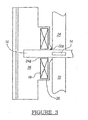
- valve body that includes the present invention is generally shown at 10. Shown herein, the invention is preferably used in an illustrative throttle body, generally indicated at 12, of an engine.
- the engine may be of the internal combustion variety; however, it is envisioned that the present invention with be compatible with other types of engines, as well.
- Valve body 10 preferably includes a valve 14 mounted on a selectively rotatable shaft 16.
- the shaft 16 is preferably rotationally coupled with the throttle body 12 by way of at least one bearing 18.
- a bypass port generally indicated at 20 preferably provides a method for allowing a fluid flow across a pressure differential or delta, e.g., from a high-pressure side to a low-pressure side. More preferably, bypass port 20 provides a bypass in the valve body 10 for allowing the flow flow from the high-pressure side of the valve body 10 generally indicated in Figure 3 at 22 to a low-pressure side 24. Still more preferably, the bypass port 20 preferably provides a bypass in the valve body 10 for allowing the fluid flow from a high-pressure side 22A adjacent the bearing 18 to a low-pressure side 24A adjacent the bearing 18.
- bypass port 20 aids in the regulation of pressure or vacuum, and is sometimes referred to as a vacuum bypass.
- the bypass port 20 could also be a pressure bypass or the like and is effectively characterized as a pressure equalization port which provides a path around the bearing 18 for pressure to pass around rather than through the bearing 18.
- While the present invention is particularly useful in any throttle body, for instance, it is particularly useful in boosted engines wherein the low-pressure to high-pressure side of the bearing 18 may have a very large delta, which in previous throttle body designs has detrimentally effected the bearing life of the shaft bearing.
- the throttle body 12 preferably includes a valve actuation side (e.g., control side chamber), generally shown at 26.
- the control side chamber 26 includes an electronic throttle control body that preferably includes drive gears or the like, contained in control side chamber 26, and a return spring mechanism generally shown at 28.
- Valve 14 is preferably in an intake chamber 30 (e.g., bore) in the throttle body 12. It should be appreciated that the present invention can be practiced with open throttle systems, as well as closed throttle systems.
- the bypass port 20 (e.g., passage) of the present invention preferably provides an egress on the outside portion 32 of the bearing 18, along the axial direction of the shaft 16. While seals and close tolerances are designed around the shaft 16, axial flow along rotational shaft 16 is still a possibility.
- the bypass port 20 preferably allows such pressure to bypass the bearing 18 rather than go through the bearing 18. This preferably allows flow between the control side chamber 26 and the intake chamber 30.
- the bypass port 20 also preferably communicates with the throttle body 12 such that it provides equalization on either side of the valve 14, to provide equalization along between either the high-pressure 22 side or low-pressure 24 side of the valve body 10, which also reduces any tendency to flow through the bearing 18 during operation.
- the bypass port 20 also permits pressure equalization between high-pressure side 22A and low-pressure side 24A adjacent bearing 18.
- the bypass port 20 can either be a "U,” “L,” or other suitably shaped channel communicating with the shaft 16 on either side of the bearing 18 or, alternatively, the "U,” “L,” or other suitably shaped bypass port 20 could be in communication with the intake chamber 30 on one of the high-pressure 22 or low-pressure 24 sides.
- the bypass port 20 can be configured in a straight channel shape.
- a second bearing 34 is preferably provided on the opposite end of the shaft 16 and is sealed in place by the seal 36.
- an additional bypass port or channel (not shown) could be used on the opposite side of the shaft 16.
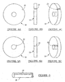
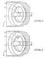
- the bypass port 20 is preferably milled into the valve body 10 or molded into the valve body 10 at the bearing location. It should be appreciated that in an alternate embodiment the bypass port 20 could be configured into either an exterior surface (as generally shown in Figs. 4A-4C) and/or interior surface of the bearing 18 (either milled or molded in), as shown generally in Figures 5A-5C.
- bypass port 20 can be configured into a surface (e.g., exterior) of the shaft 16 (either milled or molded in), as generally shown in Fig. 6.
- bypass port 20 can be configured into a surface (e.g., interior) of the throttle body 12, as generally shown in Figures 7A-7C.
- bypass port 20 can be incorporated into the various components of the valve body 10 are shown in Figs. 8-11.
- the bypass port 20 is incorporated into an interior surface of the bearing 18, as previously depicted in Figs. 4A-4C.
- the high-pressure side 22A can communicate with the low-pressure side 24A, without harming or causing damage to the bearing 18 and/or shaft 16 (e.g., contamination or loss of lubricant).
- the bypass port 20 is incorporated into an exterior surface of the bearing 18.
- the high-pressure side 22A can communicate with the low-pressure side 24A, without harming or causing damage to the bearing 18 and/or shaft 16 (e.g., contamination or loss of lubricant).
- the bypass port 20 is incorporated into a surface of the throttle body 12.
- the high-pressure side 22A can communicate with the low-pressure side 24A, without harming or causing damage to the bearing 18 and/or shaft 16 (e.g., contamination or loss of lubricant).
- the bypass port 20 is incorporated into an exterior surface of the shaft 16.
- the high-pressure side 22A can communicate with the low-pressure side 24A, without harming or causing damage to the bearing 18 and/or shaft 16 (e.g., contamination or loss of lubricant).
Landscapes
- Engineering & Computer Science (AREA)
- Chemical & Material Sciences (AREA)
- Combustion & Propulsion (AREA)
- Mechanical Engineering (AREA)
- General Engineering & Computer Science (AREA)
- Lift Valve (AREA)
- Control Of Throttle Valves Provided In The Intake System Or In The Exhaust System (AREA)
Applications Claiming Priority (4)
| Application Number | Priority Date | Filing Date | Title |
|---|---|---|---|
| US47435403P | 2003-05-30 | 2003-05-30 | |
| US474354P | 2003-05-30 | ||
| US789399 | 2004-02-27 | ||
| US10/789,399 US7337764B2 (en) | 2003-05-30 | 2004-02-27 | Pressure balanced bearing |
Publications (1)
| Publication Number | Publication Date |
|---|---|
| EP1482151A2 true EP1482151A2 (de) | 2004-12-01 |
Family
ID=33135335
Family Applications (1)
| Application Number | Title | Priority Date | Filing Date |
|---|---|---|---|
| EP20040252871 Withdrawn EP1482151A2 (de) | 2003-05-30 | 2004-05-18 | Mit Druck ausgeglichenes Lager |
Country Status (2)
| Country | Link |
|---|---|
| US (2) | US7337764B2 (de) |
| EP (1) | EP1482151A2 (de) |
Families Citing this family (6)
| Publication number | Priority date | Publication date | Assignee | Title |
|---|---|---|---|---|
| US7337764B2 (en) * | 2003-05-30 | 2008-03-04 | Borgwarner Inc. | Pressure balanced bearing |
| US20070086688A1 (en) * | 2005-10-17 | 2007-04-19 | Rexnord Industries, Llc | Vented bearing assembly |
| JP2008101672A (ja) * | 2006-10-18 | 2008-05-01 | Aisan Ind Co Ltd | バタフライバルブ及び内燃機関用吸気制御装置 |
| US8152449B2 (en) * | 2008-12-10 | 2012-04-10 | Honeywell International Inc. | Vacuum generator seal |
| DE102010004657B4 (de) * | 2010-01-14 | 2012-03-22 | Knorr-Bremse Systeme für Nutzfahrzeuge GmbH | Frischgasversorgungsvorrichtung für eine Verbrennungsmaschine und Verfahren zum Betrieb einer solchen Frischgasversorgungsvorrichtung |
| US9970450B1 (en) | 2017-01-26 | 2018-05-15 | Borgwarner Inc. | Vented bearing retainer for turbomachines |
Family Cites Families (11)
| Publication number | Priority date | Publication date | Assignee | Title |
|---|---|---|---|---|
| US1731895A (en) * | 1928-01-06 | 1929-10-15 | Weber Engine Company | Internal-combustion engine |
| US2657943A (en) * | 1950-04-04 | 1953-11-03 | Gen Electric | Means for preventing oil creepage |
| US3466478A (en) * | 1967-01-09 | 1969-09-09 | Lear Siegler Inc | Bearing gas pressure equalizing structure |
| US3729128A (en) * | 1971-09-23 | 1973-04-24 | Pennwalt Corp | High pressure centrifuge lubrication system |
| US3984159A (en) * | 1974-09-25 | 1976-10-05 | Allis-Chalmers Corporation | Apparatus for equalizing radial load on plurality of pivoted bearing pads |
| US4456266A (en) * | 1981-12-14 | 1984-06-26 | General Electric Company | Throttle bushing |
| JPS62228693A (ja) * | 1986-03-31 | 1987-10-07 | Aisin Seiki Co Ltd | ル−ツブロア |
| US5559379A (en) * | 1993-02-03 | 1996-09-24 | Nartron Corporation | Induction air driven alternator and method for converting intake air into current |
| GB9914150D0 (en) * | 1999-06-18 | 1999-08-18 | Rotech Holdings Limited | Improved pump |
| US6966746B2 (en) * | 2002-12-19 | 2005-11-22 | Honeywell International Inc. | Bearing pressure balance apparatus |
| US7337764B2 (en) * | 2003-05-30 | 2008-03-04 | Borgwarner Inc. | Pressure balanced bearing |
-
2004
- 2004-02-27 US US10/789,399 patent/US7337764B2/en not_active Expired - Fee Related
- 2004-05-18 EP EP20040252871 patent/EP1482151A2/de not_active Withdrawn
-
2008
- 2008-01-03 US US12/006,557 patent/US20080173279A1/en not_active Abandoned
Also Published As
| Publication number | Publication date |
|---|---|
| US20040241025A1 (en) | 2004-12-02 |
| US7337764B2 (en) | 2008-03-04 |
| US20080173279A1 (en) | 2008-07-24 |
Similar Documents
| Publication | Publication Date | Title |
|---|---|---|
| US20080173279A1 (en) | Pressure balanced bearing | |
| EP0357246B1 (de) | Wellendichtungseinrichtung für Turbolader | |
| JP2012057622A (ja) | 換気手段を有する減圧ポンプ | |
| EP1126186B1 (de) | Lagervorrichtung mit modularer und nachgiebiger Dichtung | |
| US20090317031A1 (en) | Roller bearing unit and gas control valve arrangement comprising a roller bearing unit | |
| US11306645B2 (en) | Cooling water control valve device | |
| EP3364080B1 (de) | Hochtemperaturwellendichtung für ein entlüftungsventil mit wälzlagern | |
| CN107110031A (zh) | 阀装置 | |
| US20060070655A1 (en) | Valve | |
| US7913389B2 (en) | Method of making a flapper valve assembly | |
| WO2012175275A1 (de) | Brennkraftmaschine mit zumindest einem zylinder | |
| US8342148B2 (en) | Throttle valve for internal combustion engine | |
| EP1846640B1 (de) | Schmierung von kompressor-schieberventil | |
| CN104067038B (zh) | 特别是用于机动车辆发动机的阀 | |
| JP7228402B2 (ja) | ターボチャージャ用コンプレッサハウジング及びその製造方法 | |
| US6520758B1 (en) | Screw compressor assembly and method including a rotor having a thrust piston | |
| US9010366B2 (en) | Pneumatic port shield | |
| JPH11210503A (ja) | スロットルボデーの軸受装置 | |
| JP2010106738A (ja) | 内燃機関のスロットル装置 | |
| WO2022202423A1 (ja) | 電動ポンプ | |
| JP2012172519A (ja) | フラップバルブ | |
| CN111173752A (zh) | 一种可增加活塞行程的进气阀 | |
| CN101523046B (zh) | 压缩机滑阀阀座 | |
| CN223410923U (zh) | 集成主动式pcv阀的缸盖罩 | |
| EP2857688B1 (de) | Rotationsverdichter |
Legal Events
| Date | Code | Title | Description |
|---|---|---|---|
| PUAI | Public reference made under article 153(3) epc to a published international application that has entered the european phase |
Free format text: ORIGINAL CODE: 0009012 |
|
| AK | Designated contracting states |
Kind code of ref document: A2 Designated state(s): AT BE BG CH CY CZ DE DK EE ES FI FR GB GR HU IE IT LI LU MC NL PL PT RO SE SI SK TR |
|
| AX | Request for extension of the european patent |
Extension state: AL HR LT LV MK |
|
| RAP1 | Party data changed (applicant data changed or rights of an application transferred) |
Owner name: BORGWARNER INC. |
|
| STAA | Information on the status of an ep patent application or granted ep patent |
Free format text: STATUS: THE APPLICATION HAS BEEN WITHDRAWN |
|
| 18W | Application withdrawn |
Effective date: 20091112 |