EP1482104A1 - Système modulaire ajustable de sécurité pour échafaudage - Google Patents
Système modulaire ajustable de sécurité pour échafaudage Download PDFInfo
- Publication number
- EP1482104A1 EP1482104A1 EP03076651A EP03076651A EP1482104A1 EP 1482104 A1 EP1482104 A1 EP 1482104A1 EP 03076651 A EP03076651 A EP 03076651A EP 03076651 A EP03076651 A EP 03076651A EP 1482104 A1 EP1482104 A1 EP 1482104A1
- Authority
- EP
- European Patent Office
- Prior art keywords
- base
- elements
- base element
- scaffolding structure
- scaffolding
- Prior art date
- Legal status (The legal status is an assumption and is not a legal conclusion. Google has not performed a legal analysis and makes no representation as to the accuracy of the status listed.)
- Granted
Links
Images






Classifications
-
- E—FIXED CONSTRUCTIONS
- E04—BUILDING
- E04G—SCAFFOLDING; FORMS; SHUTTERING; BUILDING IMPLEMENTS OR AIDS, OR THEIR USE; HANDLING BUILDING MATERIALS ON THE SITE; REPAIRING, BREAKING-UP OR OTHER WORK ON EXISTING BUILDINGS
- E04G3/00—Scaffolds essentially supported by building constructions, e.g. adjustable in height
- E04G3/22—Scaffolds essentially supported by building constructions, e.g. adjustable in height supported by roofs or ceilings
-
- E—FIXED CONSTRUCTIONS
- E04—BUILDING
- E04G—SCAFFOLDING; FORMS; SHUTTERING; BUILDING IMPLEMENTS OR AIDS, OR THEIR USE; HANDLING BUILDING MATERIALS ON THE SITE; REPAIRING, BREAKING-UP OR OTHER WORK ON EXISTING BUILDINGS
- E04G3/00—Scaffolds essentially supported by building constructions, e.g. adjustable in height
- E04G3/24—Scaffolds essentially supported by building constructions, e.g. adjustable in height specially adapted for particular parts of buildings or for buildings of particular shape, e.g. chimney stacks or pylons
- E04G3/26—Scaffolds essentially supported by building constructions, e.g. adjustable in height specially adapted for particular parts of buildings or for buildings of particular shape, e.g. chimney stacks or pylons specially adapted for working on roofs
-
- E—FIXED CONSTRUCTIONS
- E04—BUILDING
- E04G—SCAFFOLDING; FORMS; SHUTTERING; BUILDING IMPLEMENTS OR AIDS, OR THEIR USE; HANDLING BUILDING MATERIALS ON THE SITE; REPAIRING, BREAKING-UP OR OTHER WORK ON EXISTING BUILDINGS
- E04G3/00—Scaffolds essentially supported by building constructions, e.g. adjustable in height
- E04G3/24—Scaffolds essentially supported by building constructions, e.g. adjustable in height specially adapted for particular parts of buildings or for buildings of particular shape, e.g. chimney stacks or pylons
- E04G3/26—Scaffolds essentially supported by building constructions, e.g. adjustable in height specially adapted for particular parts of buildings or for buildings of particular shape, e.g. chimney stacks or pylons specially adapted for working on roofs
- E04G3/265—Scaffolds essentially supported by building constructions, e.g. adjustable in height specially adapted for particular parts of buildings or for buildings of particular shape, e.g. chimney stacks or pylons specially adapted for working on roofs with means to adapt it to a variable pitch of the roof
-
- E—FIXED CONSTRUCTIONS
- E04—BUILDING
- E04G—SCAFFOLDING; FORMS; SHUTTERING; BUILDING IMPLEMENTS OR AIDS, OR THEIR USE; HANDLING BUILDING MATERIALS ON THE SITE; REPAIRING, BREAKING-UP OR OTHER WORK ON EXISTING BUILDINGS
- E04G5/00—Component parts or accessories for scaffolds
- E04G5/06—Consoles; Brackets
-
- E—FIXED CONSTRUCTIONS
- E04—BUILDING
- E04G—SCAFFOLDING; FORMS; SHUTTERING; BUILDING IMPLEMENTS OR AIDS, OR THEIR USE; HANDLING BUILDING MATERIALS ON THE SITE; REPAIRING, BREAKING-UP OR OTHER WORK ON EXISTING BUILDINGS
- E04G5/00—Component parts or accessories for scaffolds
- E04G5/06—Consoles; Brackets
- E04G5/065—Consoles; Brackets specially adapted for attachment to ladders
Definitions
- the present invention relates to an adjustable system safety in modular form intended for use especially as a scaffolding structure to be fixed in roof, under construction, as basic structure for DIY.
- the invention relates to a modular security system for the realization of a scaffolding structure for roof work and / or in front of a building.
- the system modular of the invention is also applicable as basic structure for DIY.
- the publication FR-A-2 801 331 describes a system adjustable security in modular form according to preamble of claim 1. More particularly, this security system includes a first element of tubular interlocking base, and a second tubular shaped base element complementary to the first basic element. A device of link stiffener is attached to the second element of base and suitable for connecting the first base element to the second base element at a predetermined angle.
- the first element modular is fixed by locking safety pins to the second modular element and, to strengthen the rigidity between the modular elements, a corner reinforcement forming a spacer between the elements tubulars used to stiffen the security.
- These structures generally consist of different nestable elements fixed to each other and routed to the site.
- an object of the present invention is to provide a modular security system that offers great ease of implementation while being very reliable.
- Another object of the present invention is to propose a security system to form a scaffolding whose structural design allows mount with basic elements, of simple design, easy to transport and compact, rigid and complex scaffolding structure with one or multiple levels of work, these levels of work can be in the same vertical plane or offset by so as to give great flexibility to the whole of the scaffolding structure.
- Another object of the present invention is to provide a security system such as scaffolding whose design allows quick and easy variation dimensions of the scaffolding in the direction of width or height of the structure while being rigid.
- the adjustable system of security further includes the features of the characterizing part of claim 1.
- the adjustable modular safety system is characterized in that the first basic element is mounted to pivoting on the stiffening link device for allow pivoting with respect to the second element of based.
- the connection stiffening device comprises a plurality of graduation holes intended to adjust the angular position of the first next basic element different predetermined angles to the second basic element.
- the modular system of the invention further includes secure locking means suitable for engaging in graduation drilling to fix the first and second basic elements in the selected angular position.
- the stiffening device of connection includes two perforated flat elements arranged on either side of the second base element and a pivoting member offset from the second basic element.
- Graduation holes are arranged in pairs at a predetermined angle step along circular arcs centered on the pivot axis, and a double locking key is used to engage in a pair of holes and in perforations of the first basic element to fix the elements in the selected angular position.
- a preferred scaffolding structure to assemble especially on the roof and / or facade of a building of the type includes at least two adjustable systems of security according to the invention, with the two elements of additional base fitted by secure fitting.
- the adjustable security system 10 subject of the invention, as shown in Figures 1, 2 and 3 is particularly suitable for the realization a scaffolding structure to be used for work on the roof or under construction.
- This security system 10 can also be used as a basic structure for the DIY, such as making shelves, interior scaffolding for plasterer, painters, etc., and the realization of a platform on a support irregular and / or sloping.
- the idea of the concept is to compose from at least minus an articulated modular structure (basic kit) and accessories, cases to applications most varied techniques.
- This modular system 10 consists of a first base arm 12 with tubular socket and a second base arm 13 with tubular socket complementary to the first base arm 12.
- connection stiffening device 20 and 21 consisting of a double dish 20 and 21 graduated is fixed to second base arm 13 and adapted to connect the two base arms 12 and 13 at a predetermined angle.
- the first arm 12 is articulated on a free axis 14 by means of a perforation 17 allowing rotation of a selected angle between two dishes 20 and 21 joined together and the first arm 12.
- the two plates 20 and 21 have a corresponding perforation 25 for allow the passage of a pivot 14.
- the first arm 12 is pivotally mounted on the two flat stiffeners 20 and 21 by means of pivot 14 secured by blocking a suitable safety element, this pivoting operating freely relative to the second arm 13 fixed to the double plate 20 and 21 stiffener.
- Axis 14 off center relative to the fixed arm 13 allows adjustment freely the angle of connection between the two arms 12 and 13.
- the second arm 13 with large socket is preferably an axis (round, square or rectangular, ...) including a series of perforations 13a allow fixed and / or sliding adjustment from the lower part of the stiffening device 20 and 21 which has corresponding perforations 20a and 21a allowing the passage of a secure key, or bolts with safety nuts.
- the second arm 13 can be fixed permanently to the stiffening device 20a and 21a, for example by welding.
- the first arm 12 with small socket is preferably an axis (round-square section or rectangular, ...) including a series of perforations 12a allow axial rotation 14 between the double plate graduated 20 and 21 with an angle adjustment of more than 180 °. Its axis of rotation 14 is fixed from the upper part of the stiffening device 20 and 21, on an off-center axis 14 relative to the second arm 13 at by means of the central perforation 25 of the double plate 20 and 21 and the perforation 17 of the first arm 12.
- the central axis 14 is a free axis, allowing a off-axis rotation between the two arms 12 and 13.
- the latter can be reinforced according to use with bearings or other.
- the double stiffener plate 20 and 21 helps guide and report efforts in the axial line, from axis 14 off-center from this piece.
- connection stiffening device 20 and 21 comprises a plurality of holes 22 and 23 of graduation to adjust the angular position of the first arm 12 at different angles predetermined by compared to the second arm 13.
- One or more locking keys 15 and 16 are used to engage in graduation holes 22 and 23 and in corresponding perforations 12a of the first arm 12 to fix the selected angular position between the two arms 12 and 13.
- the double flat stiffener device 20 and 21 includes a pair of holes, each pair being spaced at an angle 15 degrees to the center line 25. More specifically, the holes 22 are divided into four series of holes 22a, 22b, 22c, 22d each arranged on an arc alternating at a distance of the central axis 25. On each arc of circle, the holes 22a, 22b, 22c, 22d are spaced apart 30 degrees from the central axis 25 and the arc of circles are equidistant.
- the holes of the 1st and 3rd series 22a and 22c are arranged at angles intermediate 15, 45, and 75 degrees while the holes of the 2nd and 4th series 22b and 22c are arranged at angles of 0, 30, 60, and 90 ° (in alternation) to obtain a relatively angle step small (15 °).
- the perforations 22, 23, 12a allow connections (in tension and compression), using one or more security keys 15 and 16.
- the locking device 15 and 16 has a double security key 15 and 16 and the arrangement of the holes 22, 23, and 12a makes it possible to adjust the angular position of the arm 12 relative to the arm 13 in 15 degree steps while maintaining the rigidity of the double flat stiffener 20 and 21.
- the double key safety can be formed by two keys 15 and 16 connected by a connecting element and secured by locking of a double pin or any other element of safety.
- graduated dishes 20 and 21 are either fixed or sliding and allow to report efforts in the central axial line of these parts 20 and 21.
- the link stiffening device can for example be formed of a simple dish in the form of U complementary to the sliding arm 13, with two elements similar to parts 20 and 21 and an element perpendicular that connect them.
- Traction and / or compression are located at level of the connection (s) using the security (at least one) depending on parts 12, 20, 21 sliding between them.
- the arm 13 is fixed on its base.
- the flat stiffeners 20 and 21 are either fixed or sliding.
- the graduated perforations between the arm 12 and the double plate 20 and 21 allow to stiffen the connection to the desired angle in a precise and defined manner, and be secured using a security key at minimum.
- the arm 12 and the two plates 20 and 21 guide and guarantee perfect angular stability from of the central axis 25.
- perforations 12a, 12b, 12c, 12d, 13a, 13b, 13c additional in each of the arms 12 and 13.
- These perforations can be arranged in a double offset row 12b and 13b equidistant perforations and / or a single row axial 12a, 12c, 12d, 13a, 13c of perforations equidistant in two opposite faces of the arms 12 and 13, or in all the faces of the arms 12 and 13.
- the double plate 20 and 21 is provided with perforations 20a and 21a like.
- All these perforations are intended to receive a secure connection with at least one security key after assembly by sliding socket on the other modular system or accessory up to a selected position. So these perforations allow the use of a security key (one at most) for secure connections during application modular well defined.
- the security key can be formed by a stud which can be locked by means of a pin or a key.
- the security key is preferably a double U-shaped key with two elements spaced so as to ability to fit into two adjacent perforations in the offset double row 12b and 13b and / or in the single axial rows 12a, 12c, 12d, 13a, 13c, 20a, and 21a.
- the basic system 10 alone allows simple application as a movable and modular stand. This basic system allows a foot adjustment according of the declination of support to obtain a platform stable. The desired angle is secured with a key safety and sliding and adjustable rails allow perfect stability.
- the basic system adapts to numerous scaffolding installation configurations: posed on the ground, posed on a staircase, in roofing, in wall crossing, crawling base, or ladder.
- the structure safety scaffolding shown in Figures 4 to 17, is a structure called of the type carried by the construction. It is more particularly intended for be used for the realization or maintenance of roofs of a building or as scaffolding vertical along a wall of a building.
- the scaffolding structure is provided with a member coupling 40 for hanging the scaffolding to an element of construction.
- the building element on which is fixed the scaffolding can be a wall or an element of frame of said construction.
- the element of construction consists of a roof 2.
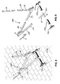
- the scaffolding 100 of FIG. 4 consists of two modular systems 10 and 110 of the type of the figure 1 nested and in position connected to a roof 2. This scaffolding is more particularly suited to the realization or repair of the roof of construction.
- This suspended scaffolding 110 comprises a coupling structure 40 arranged to be connected to said construction by at least one point anchor 40 and a support structure 120 comprising at minus a support point 50 located at levels different from the roof 2.
- the end of the double flat 20 and 21 forms a gripping head 40 by means of corresponding perforations.
- This structure scaffolding 100 comprises at least two modules 10 and 110 with two arms as shown in FIG. 1.
- This suspended scaffolding structure arranged to connect to the building by at least one anchor point 40 and several support points 50 to 54 located on different levels, includes at least two modular systems 10 and 110.
- Each modular system 10 and 110 of the scaffolding structure is adjustable to change the tilt angle according to needs and, by pivoting the arms, to constitute each time a horizontal floor element support and a vertical railing element support, regardless of the inclination of the roof.
- each element modular 10 and 110 of the scaffolding module is generally arranged substantially orthogonally to building element 2.
- the first modular system 110 of the scaffolding module 100 is connected by an anchor head 40 on a hook service 41 and by four support points 50-53 to building element 2.
- the two elements modular 10 and 110 are fitted into each other by fitting of complementary tubular arms 13 and 112.
- the first arm 12 forming an upright is adapted to support security features such as elements of guardrails or nets, and the second arm 13 forms a base in order to create a platform for job.
- the support points 50 to 54 are preferably distributed laterally by the use of a nestable T-profile 120 in the second arm 113.
- Profile 120 is composed of two axes (round, square, or rectangular section, .7) symmetrically juxtaposed on one of its ends.
- Perforations 121 and 122 allow the use of security keys for connections secure during well-defined modular applications.
- This part 120 can be used both downwards and upwards.
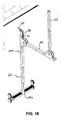
- the support points 50 to 54 can be distributed longitudinally by the addition of a joint 130 and 131 on casters 134 and 135 on either side of the base of profile 120 T-shaped joint 130 and 131 has a flat 140 shaped like a "banana". Its central axis serves as a means of connection (pin), with a support connector 150 and 151 with secure sliding socket. Both perforations in plate 140 receive the articulation of wheels 134 and 135 or other support systems (figure 18).
- the articulation on casters 130 and 131 allows besides facilitating the transport of the structure and hanging it, on the roof or along of a construction by means of a stay cable and thus avoid the risk of accident during its installation.
- the sliding connector 150 and 151 is a accessory which can be used on any support. he consists of an axis 153 (round, square or rectangular ...), which can slide freely on both sides and others from the T 120 axis, can be used in all sense (bottom or top).
- the support device 150 is perforated to receive secure connections during precise modular applications.
- the curvature 154 in U making up the part 150 and 151 allows to serve as support.
- the tubular axis 155 fixed to the right of the axis and the curvature of this part 150 and 151 makes it possible to receive the axis 136 of the joint 130 and 131 on casters.
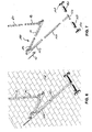
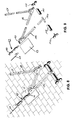
- Figures 6, 7, 8 and 9 illustrate the possibility extend the arms 12 and 113 of the modular systems 10 and 110 by adding extensions 60, 61 and 160 of different lengths.
- These extensions 60, 61 and 160 each form an axis (round, square or rectangular ...), composed of two welded parts whose section is different, to allow a secure nesting on the arms 12, 13, 112, 113 (male-female), using one (at least) security key, for applications modular defined.
- an extension 60 of length medium is fitted to the arm 12 for the railing and a large elongated 160 is fitted to the arm 113 and to the profile 120 for supporting the wheels on points away from the roof 2.
- the accessories therefore allow all use security key (one at most) for connections secure during well-defined modular applications.
- the system modular 110 can be connected by its anchor point 40 on the service hook 41 by means of a hook mobile damping unit 42, comprising one or more chain links 140 (figure 18).
- This movable hanger 42 is composed of one or several 140 banana-shaped dishes with perforations identical to those of joint 130 and 131 on casters but used in another application.
- the mobile hook 42 in the form of a chain allows to absorb the load on the different elements components.
- a separation plate 43 can be introduced under anchor point 40 to avoid damage the roof.
- This scaffolding structure can be adapted to any type of slope.
- the attachment head 40 of the double plate adapts to any type of anchor (service hook, etc.), and all of the concept can be fitted with a safety sling. All accessories can be used depending on the requirements encountered: articulation on casters, smooth adjustable, shock absorber, etc.
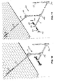
- FIGS 10, 11 and 12 illustrate a structure scaffolding 200 consisting of three systems modular 10, 110 and 210, usable as a sub-cornice.
- this structure includes a hinge 130 and 131 on casters, a T-shaped profile 120, a hook damping mobile 42, and extensions 60 and 61 short, medium or long for support and / or railing to choose according to the situation.
- this scaffolding structure may include an additional extension 62 for plug-in connection on arm 12 and providing an anchor head extended for the movable damping hook 42 for work in the sub-cornice.
- FIG. 12 illustrates a structure of scaffolding 200 similar comprising an extension 62 additional to ensure a displacement in height, and to allow secure access for work lower down under the cornice.
- This structure 200 can be used in the form of guardrails and secure means of access for work difficult to access with a system composed of three modular systems. Support for the concept in part bass is done either by T-bar (fixed or mobile) or by articulation on caster.
- the anchoring is done in the upper part using a temporary or final catch.
- a wall hook 70 fixed to a building wall 3 is provided with a member hooking 72 to the wall 3 on the one hand and on the other hand of a coupling member 70 to the anchoring head 40 of the scaffolding structure 100.
- the fastening member 70 is preferably inserted between two blocks of construction of wall 3 and fixed on the other side of the wall by a security element passing through the bore 72.
- the scaffolding structure 100 intended to be coupled, by means of the coupling member 70 to the wall 3 includes a support device 120, 130 and 131 to casters sliding against the wall as described more high.
- an extension 60 for railing can be fitted to the arm 12 if necessary.
- an extension 62 allowing a displacement in height can be nested between the T-profile 120 and the modular system 110 to allow a displacement in height along the wall 3 and move the support points in the lower part.
- a simple mobile hook 42 composed of two dishes 140 in "banana" shape can be hung on the organ coupling 70 to facilitate the installation of the scaffolding structure.
- FIGS 16 and 17 illustrate a structure scaffolding 300 usable on a ladder 310.
- this structure 300 comprises two systems modular 10 and 110 and is hung or supported on two steps spaced from the 310 scale.
- Structure 300 comprises two T-shaped profiles 120 and four sliding hook elements 150.
- a first profile 120 in T is fixed by dowel and pins safety on the double dish 20 and 21 and the second profile 120 in T is fitted in the arm 13.
- the corresponding perforations allow the use of security keys for secure connections.
- Sliding hooking elements 150 are provided to be used on a standard scale. They have an axis 153 (round, square or rectangular ...), can slide freely on both sides of the axis in T 120, usable in all directions (bottom or high).
- This part 150 is perforated in order to receive secure connections during modular applications accurate.
- the curvature 154 in U making up the part 150 allows to serve as support or grip on the 311 step and 312 of scale 310.
- the circular axis 155 fixed to the right of the axis 153 and of the curvature 154 of this part 150 makes it possible to receive the axis of the roller support 130 and 131.
- the structure 300 may include a nested extension between arm 13 and profile 150 to take support on a lower rung of the scale.
- This structure 300 makes it possible to modulate a small scaffolding adaptable to any type of ladder standardized.
- the concept consists of a support head and single or double grip.
- the accessories are usable according to the requirements encountered.
- the assembly game of two modular systems 10 and 110 solves many scenarios, applicable in fields as varied as construction, industry, and DIY, under one new application approach.
- the floor elements are arranged horizontally so as to form a first working level for the operator and able to support a floor.
- one of the vertical arms of the modular system constitutes a railing which can be shaped to receive items, such as boards, connecting two vertical sides of adjacent modular systems between them to form a smooth.
- one any of the base arms 12 and 13 of the system modular 10 can receive by locked socket either another modular system 110 or an accessory comprising a tubular shaped interlocking element complementary, such as an extension 60, 61, 62, or a profile 120 in T.
- each modular system can be used to receive other sliding elements such as example an extension 61 with one or more hooks 65 extendable railings (see Figure 19) for allow the dimensions of the structure to be varied according to the situation at hand.
- other sliding elements such as example an extension 61 with one or more hooks 65 extendable railings (see Figure 19) for allow the dimensions of the structure to be varied according to the situation at hand.
- the sockets of modular systems and accessories are all locked by connections secured through the perforations of the various components, for example by means of studs fitted with safety pins or keys.
- each modular element 10 is made by means of tubular bodies with cross-section any to have free ends likely to be connected to a free end of a body tubular of a contiguous element. It is thus possible to connect, above the modular structure 10 and 100 shown in the figures, not just a railing, but an identical modular structure for form a double platform (two floors) by single interlocking locked free ends of bodies tubular constituting the vertical sides of the system basic modular 10.
- each scaffolding structure basic another second modular system 10 by simple socket locked respectively in each free end of the tubular bodies making up this additional modular system and in each corresponding free end of modular elements components of the basic modular system to form a staircase scaffolding.
- the scaffolding structures allowing, so in itself known, to delimit a path of circulation of stakeholders, this circulation can be carried out safely thanks to the presence of a guardrail (not shown) consisting of boards supported by the vertical arms of the adjacent modular systems, and a floor (not shown) made up of planks supported by the horizontal arms.
- a guardrail (not shown) consisting of boards supported by the vertical arms of the adjacent modular systems
- a floor (not shown) made up of planks supported by the horizontal arms.
- such a structure prevents any risk of tipping and any risk of entrainment rotating the scaffolding structure around a substantially vertical axis passing through its fulcrum on the construction and its point of attachment to the body of attachment of the device.
- Such a limiting device therefore significantly the risk of accident.
- the protection system of the invention is very reliable especially through the use of devices link stiffeners and secure connections between the various constituent elements.
- the device of the invention is easy to transport by pivoting of the arms of the modular systems in position parallel.
- Such a scaffolding construction therefore allows to get with basic, design elements simple, easy to transport and compact, a complex scaffolding structure with one or more work levels, these work levels can be in the same vertical plane or offset so as to give great flexibility to the whole scaffolding structure without harming the mountain and the installation of this scaffolding on the element of construction.
- the articulation device on casters can be modified or eliminated, support being assured against the roof or against the building wall by the base of the T-profile, if lower cost was desired.
Landscapes
- Engineering & Computer Science (AREA)
- Architecture (AREA)
- Mechanical Engineering (AREA)
- Civil Engineering (AREA)
- Structural Engineering (AREA)
- Emergency Lowering Means (AREA)
- Movable Scaffolding (AREA)
- Emergency Alarm Devices (AREA)
- Burglar Alarm Systems (AREA)
- Earth Drilling (AREA)
Abstract
Description
Claims (12)
- Système ajustable de sécurité (10) sous forme modulable destiné à être utilisé notamment comme structure d'échafaudage à fixer en toiture, en construction, et/ou comme structure de base pour le bricolage, le système comprenant:caractérisé en ce que le premier élément de base (12) est monté à pivotement (14) sur le dispositif raidisseur de liaison (20, 21) pour permettre un pivotement par rapport au second élément de base (13),un premier élément de base (12) à emboítement de forme tubulaire,un second élément de base (13) à emboítement de forme tubulaire complémentaire au premier élément de base (12), etun dispositif raidisseur de liaison (20, 21) fixé au second élément de base (13) et adapté à raccorder le premier élément de base (12) au second élément de base (13) suivant un angle prédéterminé,
en ce que le dispositif raidisseur de liaison (20, 21) comporte une pluralité de perçages de graduation (22, 23) pour ajuster la position angulaire du premier élément de base (12) parmi différents angles de pivotement prédéterminés par rapport au second élément de base (13),et
en ce que le système comprend en outre un moyen de verrouillage (15, 16) sécurisé adapté pour s'engager dans les perçages de graduation (22, 23) pour fixer les premier et second éléments de base (12, 13) dans une position angulaire sélectionnée. - Système ajustable de sécurité (10) selon la revendication 1, caractérisé en ce que le dispositif raidisseur de liaison (20, 21) comprend deux éléments plats (20, 21) disposés de part et d'autre du second élément de base (13), les deux éléments plats (20, 21) et le second élément de base (13) comportant chacun une série de perforations (20a, 21a, 13a) respectives destinées à recevoir un organe de connection afin de fixer les éléments (20, 21, 13) entre eux.
- Système ajustable de sécurité (10) selon l'une des revendications 1 à 2, caractérisé en ce que le dispositif raidisseur de liaison (20, 21) comprend un organe de pivotement (14) désaxé par rapport au second élément de base (13) permettant une rotation désaxée entre les premier et second éléments de base (12, 13).
- Système ajustable de sécurité (10) selon l'une des revendications 1 à 3, caractérisé en ce que les perçages de graduation (22a, 22b, 22c, 22d) sont disposés par paires suivant un pas d'angle prédéterminé sur plusieurs d'arcs de cercle centrés sur l'axe de pivotement (25) du dispositif raidisseur (20, 21), et
en ce que le moyen de verrouillage (15, 16) comprend une double clé (15, 16) pour s'engager dans deux paires de perçages (22a, 22b, 22c, 22d, 23) et dans des perforations (12a) correspondantes du premier élément de base (12), la double clé étant verrouillable par un organe de sûreté. - Système ajustable de sécurité (10) selon l'une des revendications 1 à 4, caractérisé en ce que les premier et second éléments de base (12, 13) comportent chacun au moins une rangée de perforations (12a, 12b, 12c, 12d, 13a, 13b, 13c) équidistantes, les perforations équidistantes étant disposées suivant deux rangées désaxées (12b et 13b) de perforations équidistantes et/ou suivant une simple rangée axiale (12a, 12c, 12d, 13a, 13c) de perforations équidistantes dans au moins deux faces opposées des premier et second éléments de base (12, 13) et
en ce que les perforations équidistantes (12a-12d, 13a-13c) sont destinées à recevoir une connexion sécurisée avec au moins une clé de sûreté après assemblage ou emboítement coulissant d'un accessoire jusqu'à une position sélectionnée sur l'un des éléments de base (12, 13). - Structure d'échafaudage à monter notamment en toiture et/ou en façade d'une construction du type comprenant au moins deux systèmes ajustables de sécurité (10, 210) selon l'une des revendications 1 à 5,
caractérisée en ce que le premier élément de base (112) du premier système ajustable de sécurité (110) est emboítable à coulissement dans le second élément de base (13) complémentaire du deuxième système ajustable de sécurité (10), l'emboítement étant sécurisé au moyen d'une connexion de sûreté,
en ce que la structure d'échafaudage comprend au moins un organe d'attelage (40; 42;62; 70; 150) solidaire des premiers et second systèmes ajustables de sécurité emboítés (10, 100) pour accrocher la structure d'échafaudage à un élément (41; 3; 311) fixe par rapport à la construction, et
en ce qu'elle comprend en outre au moins un organe d'appui (120, 130, 131; 150) solidaire des premiers et second systèmes de sécurité emboítés (10, 110) pour prendre appui en au moins un point fixe (50-54, 312) différent par rapport à la construction. - Structure d'échafaudage selon la revendication 6, caractérisée en ce que l'organe d'appui (120, 130, 131; 150) comprend:un profilé en T (120) ayant un axe (121) à emboítement sécurisé de forme tubulaire complémentaire au second élément de base (13, 113) des premiers et second systèmes ajustables (10, 110) et une base (122) de forme tubulaire, etune paire de connecteurs (150, 151) à emboítement sécurisé emboítables sur la base (122) de l'organe d'appui.
- Structure d'échafaudage selon l'une des revendications 6 et 7, caractérisée en ce que l'organe d'appui (120, 130, 131, 150) comprend en outre un élément (154) courbé en U permettant de servir d'appui ou d'accroche sur tout support tel qu'un échelon (311, 312) d'une échelle (310) normalisée.
- Structure d'échafaudage selon l'une des revendications 6 à 8, caractérisée en ce que l'organe d'appui (120, 130, 131, 150) comprend en outre un axe tubulaire (155) fixé sur chaque connecteur à emboítement (150, 151) de chaque côté de la base (122), et
une articulation (130, 131) sur roulettes de chaque côté de la base (122), chaque articulation (130, 131) comportant un plat (140, 141) supportant deux roues (134, 135) et un axe central (136) pour s'engager de manière sécurisée dans l'axe tubulaire (155) de l'organe d'appui. - Structure d'échafaudage selon l'une des revendications 6 à 9, caractérisée en ce que l'organe d'attelage (40; 42; 62; 70; 150) comprend une tête d'ancrage (40) intégrale au dispositif raidisseur de liaison (21, 21) du premier ou du second système ajustable (10, 100).
- Structure d'échafaudage selon l'une des revendications 6 à 10, caractérisée en ce que l'organe d'attelage (40, 42) comprend en outre une accroche mobile (42) composée de plusieurs plats courbés (140) interconnectés par des connecteurs sécurisés pour amortir la charge sur la structure d'échafaudage.
- Structure d'échafaudage selon l'une des revendications 6 à 11, caractérisée en ce que la structure comprend en outre une ou plusieurs allonges (60, 61, 62, 160) pouvant coulisser et s'emboíter de manière sécurisée sur les premiers et second éléments de base (12, 13, 112, 113),
chaque allonge (60, 61, 62, 160) étant formée de deux éléments soudés de sections différentes complémentaires aux éléments de base (12, 13, 112, 113) et comportant des perforations correspondantes pour permettre un emboítement sécurisé au moyen d'une connexion de sûreté.
Priority Applications (7)
| Application Number | Priority Date | Filing Date | Title |
|---|---|---|---|
| EP03076651A EP1482104B1 (fr) | 2003-05-28 | 2003-05-28 | Système modulaire ajustable de sécurité pour échafaudage |
| ES03076651T ES2298470T3 (es) | 2003-05-28 | 2003-05-28 | Sistema modular de seguridad para andamio. |
| PT03076651T PT1482104E (pt) | 2003-05-28 | 2003-05-28 | Sistema modular de segurança para andaime |
| AT03076651T ATE377119T1 (de) | 2003-05-28 | 2003-05-28 | Einstellbares modulares sicherheitssystem für gerüste |
| SI200331103T SI1482104T1 (sl) | 2003-05-28 | 2003-05-28 | Prilagodljiv modularni varnostni sistem, ki bi se naj uporabljal predvsem kot konstrukcija za gradbene odre |
| DK03076651T DK1482104T3 (da) | 2003-05-28 | 2003-05-28 | En tilpassende modulsikkerhedssystem som formentlig bruges især som stilladsstruktur |
| DE60317171T DE60317171T2 (de) | 2003-05-28 | 2003-05-28 | Einstellbares modulares Sicherheitssystem für Gerüste |
Applications Claiming Priority (1)
| Application Number | Priority Date | Filing Date | Title |
|---|---|---|---|
| EP03076651A EP1482104B1 (fr) | 2003-05-28 | 2003-05-28 | Système modulaire ajustable de sécurité pour échafaudage |
Publications (2)
| Publication Number | Publication Date |
|---|---|
| EP1482104A1 true EP1482104A1 (fr) | 2004-12-01 |
| EP1482104B1 EP1482104B1 (fr) | 2007-10-31 |
Family
ID=33104142
Family Applications (1)
| Application Number | Title | Priority Date | Filing Date |
|---|---|---|---|
| EP03076651A Expired - Lifetime EP1482104B1 (fr) | 2003-05-28 | 2003-05-28 | Système modulaire ajustable de sécurité pour échafaudage |
Country Status (7)
| Country | Link |
|---|---|
| EP (1) | EP1482104B1 (fr) |
| AT (1) | ATE377119T1 (fr) |
| DE (1) | DE60317171T2 (fr) |
| DK (1) | DK1482104T3 (fr) |
| ES (1) | ES2298470T3 (fr) |
| PT (1) | PT1482104E (fr) |
| SI (1) | SI1482104T1 (fr) |
Cited By (11)
| Publication number | Priority date | Publication date | Assignee | Title |
|---|---|---|---|---|
| FR2889220A1 (fr) * | 2005-07-29 | 2007-02-02 | Participations Soc Par Actions | Structure de securite pour l'elaboration d'echafaudage suspendu |
| FR2889222A1 (fr) * | 2005-07-29 | 2007-02-02 | Participations Soc Par Actions | "echafaudage suspendu a temoin de charge" |
| FR2914935A1 (fr) * | 2007-04-12 | 2008-10-17 | Frenehard Et Michaux Sa Ets | Structure de console d'echafaudage et systeme d'echafaudage comprenant plusieurs structures de console d'echagaudage |
| EP1748125A3 (fr) * | 2005-07-29 | 2009-06-17 | G. Participations | Structure de securite pour l'elaboration d'echafaudage |
| EP3469168A4 (fr) * | 2016-09-16 | 2019-09-18 | Diva Investments Pty Ltd as Trustee for Handrail Holding Trust | Système de rail de sécurité |
| WO2020079392A1 (fr) * | 2018-10-16 | 2020-04-23 | Astute Safety Solutions Limited | Système de fixation |
| US10662658B2 (en) | 2014-08-06 | 2020-05-26 | Fast Beam Oy | Scaffold for supporting a working platform for bridges |
| GB2606174A (en) * | 2021-04-28 | 2022-11-02 | Trad Hire & Sales Ltd | Improvements in or relating to barrier systems |
| US12044021B2 (en) * | 2021-04-20 | 2024-07-23 | Russell Schwartz | Roofer support apparatus |
| EP4411089A1 (fr) * | 2023-01-31 | 2024-08-07 | KREBS, Samuel | Dispositif et système de sécurisation pour travaux sur des toits inclinés |
| US12709900B1 (en) * | 2023-02-01 | 2026-08-18 | Consolidated Electrical Distributors, Inc. | Apparatus for placement of materials on a roof |
Families Citing this family (2)
| Publication number | Priority date | Publication date | Assignee | Title |
|---|---|---|---|---|
| USD603530S1 (en) | 2007-05-22 | 2009-11-03 | Marc Antoine | Connector bracket |
| DE202023101096U1 (de) * | 2023-01-31 | 2024-05-02 | Samuel Krebs | Sicherungsvorrichtung und System für Arbeiten auf geneigten Dächern |
Citations (5)
| Publication number | Priority date | Publication date | Assignee | Title |
|---|---|---|---|---|
| FR1332079A (fr) * | 1963-12-16 | |||
| NL6405963A (fr) * | 1963-05-28 | 1964-11-30 | ||
| EP0930407A1 (fr) * | 1998-01-16 | 1999-07-21 | Dimos, Société Anonyme | Dispositif pour l'accrochage d'une structure d'échafaudage |
| FR2801331A1 (fr) * | 1999-11-19 | 2001-05-25 | Dimos | Structure de securite pour le travail en toiture |
| EP1215354A2 (fr) * | 2000-12-14 | 2002-06-19 | Franco Stefanelli | Dispositif de protection de personnes travaillant sur des toitures d'immeubles ou similaires et permettant de supporter des travailleurs lors de travaux en bordure de toitures |
-
2003
- 2003-05-28 SI SI200331103T patent/SI1482104T1/sl unknown
- 2003-05-28 PT PT03076651T patent/PT1482104E/pt unknown
- 2003-05-28 EP EP03076651A patent/EP1482104B1/fr not_active Expired - Lifetime
- 2003-05-28 DK DK03076651T patent/DK1482104T3/da active
- 2003-05-28 DE DE60317171T patent/DE60317171T2/de not_active Expired - Lifetime
- 2003-05-28 ES ES03076651T patent/ES2298470T3/es not_active Expired - Lifetime
- 2003-05-28 AT AT03076651T patent/ATE377119T1/de active
Patent Citations (5)
| Publication number | Priority date | Publication date | Assignee | Title |
|---|---|---|---|---|
| FR1332079A (fr) * | 1963-12-16 | |||
| NL6405963A (fr) * | 1963-05-28 | 1964-11-30 | ||
| EP0930407A1 (fr) * | 1998-01-16 | 1999-07-21 | Dimos, Société Anonyme | Dispositif pour l'accrochage d'une structure d'échafaudage |
| FR2801331A1 (fr) * | 1999-11-19 | 2001-05-25 | Dimos | Structure de securite pour le travail en toiture |
| EP1215354A2 (fr) * | 2000-12-14 | 2002-06-19 | Franco Stefanelli | Dispositif de protection de personnes travaillant sur des toitures d'immeubles ou similaires et permettant de supporter des travailleurs lors de travaux en bordure de toitures |
Cited By (13)
| Publication number | Priority date | Publication date | Assignee | Title |
|---|---|---|---|---|
| FR2889220A1 (fr) * | 2005-07-29 | 2007-02-02 | Participations Soc Par Actions | Structure de securite pour l'elaboration d'echafaudage suspendu |
| FR2889222A1 (fr) * | 2005-07-29 | 2007-02-02 | Participations Soc Par Actions | "echafaudage suspendu a temoin de charge" |
| EP1748125A3 (fr) * | 2005-07-29 | 2009-06-17 | G. Participations | Structure de securite pour l'elaboration d'echafaudage |
| FR2914935A1 (fr) * | 2007-04-12 | 2008-10-17 | Frenehard Et Michaux Sa Ets | Structure de console d'echafaudage et systeme d'echafaudage comprenant plusieurs structures de console d'echagaudage |
| US10662658B2 (en) | 2014-08-06 | 2020-05-26 | Fast Beam Oy | Scaffold for supporting a working platform for bridges |
| EP3469168A4 (fr) * | 2016-09-16 | 2019-09-18 | Diva Investments Pty Ltd as Trustee for Handrail Holding Trust | Système de rail de sécurité |
| US11976481B2 (en) | 2016-09-16 | 2024-05-07 | Aldeck Group Pty Ltd | Safety rail system |
| WO2020079392A1 (fr) * | 2018-10-16 | 2020-04-23 | Astute Safety Solutions Limited | Système de fixation |
| US12044021B2 (en) * | 2021-04-20 | 2024-07-23 | Russell Schwartz | Roofer support apparatus |
| GB2606174A (en) * | 2021-04-28 | 2022-11-02 | Trad Hire & Sales Ltd | Improvements in or relating to barrier systems |
| GB2606174B (en) * | 2021-04-28 | 2023-07-12 | Trad Hire & Sales Ltd | Improvements in or relating to barrier systems |
| EP4411089A1 (fr) * | 2023-01-31 | 2024-08-07 | KREBS, Samuel | Dispositif et système de sécurisation pour travaux sur des toits inclinés |
| US12709900B1 (en) * | 2023-02-01 | 2026-08-18 | Consolidated Electrical Distributors, Inc. | Apparatus for placement of materials on a roof |
Also Published As
| Publication number | Publication date |
|---|---|
| DE60317171D1 (de) | 2007-12-13 |
| SI1482104T1 (sl) | 2008-08-31 |
| ES2298470T3 (es) | 2008-05-16 |
| DE60317171T2 (de) | 2008-06-12 |
| PT1482104E (pt) | 2008-03-19 |
| ATE377119T1 (de) | 2007-11-15 |
| EP1482104B1 (fr) | 2007-10-31 |
| DK1482104T3 (da) | 2008-03-10 |
Similar Documents
| Publication | Publication Date | Title |
|---|---|---|
| EP1482104B1 (fr) | Système modulaire ajustable de sécurité pour échafaudage | |
| FR2975116A1 (fr) | Echafaudage pliant | |
| EP4367344A1 (fr) | Tour d'échafaudage et échafaudage et utilisation de la tour et de l'échafaudage | |
| WO2017191391A1 (fr) | Module pour réaliser un escalier de chantier tournant, ensemble comportant au moins un tel module et escalier de chantier comportant au moins un tel ensemble | |
| EP0468907A1 (fr) | Passerelle-support repliable pour banches de coffrage | |
| FR3018536A1 (fr) | Plateforme de travail en encorbellement convertible en tour d'etaiement et utilisation | |
| FR2596442A1 (fr) | Console pignon pour echafaudage ou analogue | |
| FR2946373A1 (fr) | Module pour dispositif d'acces entre deux niveaux et dispositif comprenant un tel module | |
| EP1783302A2 (fr) | Moyens d'assemblage de jambe d'appui d'échafaudage, jambe d'appui et échafaudage comprenant de tels moyens | |
| EP1109987A1 (fr) | Structure support portative utilisable en tant qu'echelle ou escabeau | |
| WO1992000432A2 (fr) | Echafaudage reglable destine a prendre appui sur une surface en pente | |
| FR3142498A1 (fr) | Tour d’échafaudage et échafaudage et utilisation de la tour et de l’échafaudage | |
| FR2510164A1 (fr) | Passerelle a consoles pliables pour travaux de batiments | |
| EP2191744A1 (fr) | Profil de reprise de charges | |
| EP2706166A1 (fr) | Tour d'étaiement modulaire pour le génie civil et le bâtiment | |
| EP0874108A1 (fr) | Dispositif pour le montage en sécurité des échafaudages | |
| FR3124814A1 (fr) | Echafaudage et utilisation de l’échafaudage | |
| FR3130866A1 (fr) | Dispositif d'ancrage pour toiture de modules de construction modulaire, et module de construction modulaire équipé d'un tel dispositif d'ancrage. | |
| FR2786797A1 (fr) | Echafaudage pour toit | |
| FR2526838A3 (fr) | Element d'echafaudage utilisant les troncons d'une echelle extensible | |
| FR3101088A1 (fr) | Echafaudage | |
| EP0580456B1 (fr) | Echafaudage | |
| FR2780429A1 (fr) | Echafaudage suspendu a elements modulaires | |
| FR2663973A1 (fr) | Plancher de travail a support tripode pour escalier. | |
| EP1686221A2 (fr) | Dispositif de montage pour pieces d'echafaudage |
Legal Events
| Date | Code | Title | Description |
|---|---|---|---|
| REG | Reference to a national code |
Ref country code: SE Ref legal event code: TRGR |
|
| PUAI | Public reference made under article 153(3) epc to a published international application that has entered the european phase |
Free format text: ORIGINAL CODE: 0009012 |
|
| AK | Designated contracting states |
Kind code of ref document: A1 Designated state(s): AT BE BG CH CY CZ DE DK EE ES FI FR GB GR HU IE IT LI LU MC NL PT RO SE SI SK TR |
|
| AX | Request for extension of the european patent |
Extension state: AL LT LV MK |
|
| 17P | Request for examination filed |
Effective date: 20050531 |
|
| 17Q | First examination report despatched |
Effective date: 20050623 |
|
| AKX | Designation fees paid |
Designated state(s): AT BE BG CH CY CZ DE DK EE ES FI FR GB GR HU IE IT LI LU MC NL PT RO SE SI SK TR |
|
| GRAP | Despatch of communication of intention to grant a patent |
Free format text: ORIGINAL CODE: EPIDOSNIGR1 |
|
| GRAS | Grant fee paid |
Free format text: ORIGINAL CODE: EPIDOSNIGR3 |
|
| GRAA | (expected) grant |
Free format text: ORIGINAL CODE: 0009210 |
|
| AK | Designated contracting states |
Kind code of ref document: B1 Designated state(s): AT BE BG CH CY CZ DE DK EE ES FI FR GB GR HU IE IT LI LU MC NL PT RO SE SI SK TR |
|
| REG | Reference to a national code |
Ref country code: GB Ref legal event code: FG4D Free format text: NOT ENGLISH |
|
| REG | Reference to a national code |
Ref country code: IE Ref legal event code: FG4D Free format text: LANGUAGE OF EP DOCUMENT: FRENCH |
|
| REG | Reference to a national code |
Ref country code: CH Ref legal event code: EP |
|
| REF | Corresponds to: |
Ref document number: 60317171 Country of ref document: DE Date of ref document: 20071213 Kind code of ref document: P |
|
| REG | Reference to a national code |
Ref country code: DK Ref legal event code: T3 |
|
| REG | Reference to a national code |
Ref country code: PT Ref legal event code: SC4A Free format text: AVAILABILITY OF NATIONAL TRANSLATION Effective date: 20080131 |
|
| GBT | Gb: translation of ep patent filed (gb section 77(6)(a)/1977) |
Effective date: 20080303 |
|
| REG | Reference to a national code |
Ref country code: ES Ref legal event code: FG2A Ref document number: 2298470 Country of ref document: ES Kind code of ref document: T3 |
|
| PG25 | Lapsed in a contracting state [announced via postgrant information from national office to epo] |
Ref country code: BG Free format text: LAPSE BECAUSE OF FAILURE TO SUBMIT A TRANSLATION OF THE DESCRIPTION OR TO PAY THE FEE WITHIN THE PRESCRIBED TIME-LIMIT Effective date: 20080131 |
|
| PG25 | Lapsed in a contracting state [announced via postgrant information from national office to epo] |
Ref country code: RO Free format text: LAPSE BECAUSE OF FAILURE TO SUBMIT A TRANSLATION OF THE DESCRIPTION OR TO PAY THE FEE WITHIN THE PRESCRIBED TIME-LIMIT Effective date: 20071031 |
|
| PLBE | No opposition filed within time limit |
Free format text: ORIGINAL CODE: 0009261 |
|
| STAA | Information on the status of an ep patent application or granted ep patent |
Free format text: STATUS: NO OPPOSITION FILED WITHIN TIME LIMIT |
|
| 26N | No opposition filed |
Effective date: 20080801 |
|
| PG25 | Lapsed in a contracting state [announced via postgrant information from national office to epo] |
Ref country code: CZ Free format text: LAPSE BECAUSE OF FAILURE TO SUBMIT A TRANSLATION OF THE DESCRIPTION OR TO PAY THE FEE WITHIN THE PRESCRIBED TIME-LIMIT Effective date: 20071031 |
|
| PG25 | Lapsed in a contracting state [announced via postgrant information from national office to epo] |
Ref country code: GR Free format text: LAPSE BECAUSE OF FAILURE TO SUBMIT A TRANSLATION OF THE DESCRIPTION OR TO PAY THE FEE WITHIN THE PRESCRIBED TIME-LIMIT Effective date: 20080201 |
|
| REG | Reference to a national code |
Ref country code: HU Ref legal event code: AG4A Ref document number: E004229 Country of ref document: HU |
|
| REG | Reference to a national code |
Ref country code: PT Ref legal event code: MM4A Free format text: LAPSE DUE TO NON-PAYMENT OF FEES Effective date: 20090302 |
|
| PG25 | Lapsed in a contracting state [announced via postgrant information from national office to epo] |
Ref country code: EE Free format text: LAPSE BECAUSE OF FAILURE TO SUBMIT A TRANSLATION OF THE DESCRIPTION OR TO PAY THE FEE WITHIN THE PRESCRIBED TIME-LIMIT Effective date: 20071031 |
|
| REG | Reference to a national code |
Ref country code: PT Ref legal event code: NF4A Free format text: RESTITUTIO IN INTEGRUM Effective date: 20090522 |
|
| PG25 | Lapsed in a contracting state [announced via postgrant information from national office to epo] |
Ref country code: PT Free format text: LAPSE BECAUSE OF NON-PAYMENT OF DUE FEES Effective date: 20090302 |
|
| PG25 | Lapsed in a contracting state [announced via postgrant information from national office to epo] |
Ref country code: CY Free format text: LAPSE BECAUSE OF FAILURE TO SUBMIT A TRANSLATION OF THE DESCRIPTION OR TO PAY THE FEE WITHIN THE PRESCRIBED TIME-LIMIT Effective date: 20071031 |
|
| PG25 | Lapsed in a contracting state [announced via postgrant information from national office to epo] |
Ref country code: IT Free format text: LAPSE BECAUSE OF NON-PAYMENT OF DUE FEES Effective date: 20080528 |
|
| PGRI | Patent reinstated in contracting state [announced from national office to epo] |
Ref country code: PT Effective date: 20090522 |
|
| PG25 | Lapsed in a contracting state [announced via postgrant information from national office to epo] |
Ref country code: TR Free format text: LAPSE BECAUSE OF FAILURE TO SUBMIT A TRANSLATION OF THE DESCRIPTION OR TO PAY THE FEE WITHIN THE PRESCRIBED TIME-LIMIT Effective date: 20071031 |
|
| REG | Reference to a national code |
Ref country code: FR Ref legal event code: PLFP Year of fee payment: 13 |
|
| PG25 | Lapsed in a contracting state [announced via postgrant information from national office to epo] |
Ref country code: BE Free format text: LAPSE BECAUSE OF NON-PAYMENT OF DUE FEES Effective date: 20160531 |
|
| REG | Reference to a national code |
Ref country code: FR Ref legal event code: PLFP Year of fee payment: 14 |
|
| PGFP | Annual fee paid to national office [announced via postgrant information from national office to epo] |
Ref country code: NL Payment date: 20161118 Year of fee payment: 14 Ref country code: SK Payment date: 20161121 Year of fee payment: 14 Ref country code: FI Payment date: 20161121 Year of fee payment: 14 Ref country code: HU Payment date: 20161115 Year of fee payment: 14 Ref country code: MC Payment date: 20161122 Year of fee payment: 14 Ref country code: DK Payment date: 20161118 Year of fee payment: 14 Ref country code: DE Payment date: 20161121 Year of fee payment: 14 Ref country code: GB Payment date: 20161122 Year of fee payment: 14 Ref country code: CH Payment date: 20161121 Year of fee payment: 14 Ref country code: FR Payment date: 20161118 Year of fee payment: 14 Ref country code: IE Payment date: 20161122 Year of fee payment: 14 |
|
| PG25 | Lapsed in a contracting state [announced via postgrant information from national office to epo] |
Ref country code: BE Free format text: LAPSE BECAUSE OF NON-PAYMENT OF DUE FEES Effective date: 20160531 |
|
| PGFP | Annual fee paid to national office [announced via postgrant information from national office to epo] |
Ref country code: PT Payment date: 20161118 Year of fee payment: 14 Ref country code: ES Payment date: 20161118 Year of fee payment: 14 Ref country code: BE Payment date: 20161118 Year of fee payment: 14 Ref country code: SE Payment date: 20161118 Year of fee payment: 14 Ref country code: AT Payment date: 20161121 Year of fee payment: 14 Ref country code: SI Payment date: 20161121 Year of fee payment: 14 |
|
| PGRI | Patent reinstated in contracting state [announced from national office to epo] |
Ref country code: BE Effective date: 20161119 |
|
| PG25 | Lapsed in a contracting state [announced via postgrant information from national office to epo] |
Ref country code: LU Free format text: LAPSE BECAUSE OF NON-PAYMENT OF DUE FEES Effective date: 20170531 |
|
| REG | Reference to a national code |
Ref country code: DE Ref legal event code: R119 Ref document number: 60317171 Country of ref document: DE |
|
| PGFP | Annual fee paid to national office [announced via postgrant information from national office to epo] |
Ref country code: LU Payment date: 20171130 Year of fee payment: 15 |
|
| REG | Reference to a national code |
Ref country code: CH Ref legal event code: PL |
|
| REG | Reference to a national code |
Ref country code: SE Ref legal event code: EUG Ref country code: DK Ref legal event code: EBP Effective date: 20170531 |
|
| REG | Reference to a national code |
Ref country code: NL Ref legal event code: MM Effective date: 20170601 |
|
| REG | Reference to a national code |
Ref country code: AT Ref legal event code: MM01 Ref document number: 377119 Country of ref document: AT Kind code of ref document: T Effective date: 20170528 |
|
| GBPC | Gb: european patent ceased through non-payment of renewal fee |
Effective date: 20170528 |
|
| PG25 | Lapsed in a contracting state [announced via postgrant information from national office to epo] |
Ref country code: FI Free format text: LAPSE BECAUSE OF NON-PAYMENT OF DUE FEES Effective date: 20170528 Ref country code: SK Free format text: LAPSE BECAUSE OF NON-PAYMENT OF DUE FEES Effective date: 20170528 Ref country code: AT Free format text: LAPSE BECAUSE OF NON-PAYMENT OF DUE FEES Effective date: 20170528 Ref country code: HU Free format text: LAPSE BECAUSE OF NON-PAYMENT OF DUE FEES Effective date: 20170529 Ref country code: MC Free format text: LAPSE BECAUSE OF NON-PAYMENT OF DUE FEES Effective date: 20170531 |
|
| REG | Reference to a national code |
Ref country code: SK Ref legal event code: MM4A Ref document number: E 4055 Country of ref document: SK Effective date: 20170528 |
|
| REG | Reference to a national code |
Ref country code: IE Ref legal event code: MM4A |
|
| PG25 | Lapsed in a contracting state [announced via postgrant information from national office to epo] |
Ref country code: SI Free format text: LAPSE BECAUSE OF NON-PAYMENT OF DUE FEES Effective date: 20170529 Ref country code: SE Free format text: LAPSE BECAUSE OF NON-PAYMENT OF DUE FEES Effective date: 20170529 Ref country code: PT Free format text: LAPSE BECAUSE OF NON-PAYMENT OF DUE FEES Effective date: 20171128 Ref country code: LI Free format text: LAPSE BECAUSE OF NON-PAYMENT OF DUE FEES Effective date: 20170531 Ref country code: CH Free format text: LAPSE BECAUSE OF NON-PAYMENT OF DUE FEES Effective date: 20170531 |
|
| REG | Reference to a national code |
Ref country code: SI Ref legal event code: KO00 Effective date: 20180111 |
|
| REG | Reference to a national code |
Ref country code: FR Ref legal event code: ST Effective date: 20180131 |
|
| PG25 | Lapsed in a contracting state [announced via postgrant information from national office to epo] |
Ref country code: NL Free format text: LAPSE BECAUSE OF NON-PAYMENT OF DUE FEES Effective date: 20170601 |
|
| REG | Reference to a national code |
Ref country code: BE Ref legal event code: MM Effective date: 20170531 |
|
| PG25 | Lapsed in a contracting state [announced via postgrant information from national office to epo] |
Ref country code: DK Free format text: LAPSE BECAUSE OF NON-PAYMENT OF DUE FEES Effective date: 20170531 Ref country code: IE Free format text: LAPSE BECAUSE OF NON-PAYMENT OF DUE FEES Effective date: 20170528 Ref country code: DE Free format text: LAPSE BECAUSE OF NON-PAYMENT OF DUE FEES Effective date: 20171201 Ref country code: GB Free format text: LAPSE BECAUSE OF NON-PAYMENT OF DUE FEES Effective date: 20170528 |
|
| PG25 | Lapsed in a contracting state [announced via postgrant information from national office to epo] |
Ref country code: FR Free format text: LAPSE BECAUSE OF NON-PAYMENT OF DUE FEES Effective date: 20170531 |
|
| REG | Reference to a national code |
Ref country code: ES Ref legal event code: FD2A Effective date: 20180703 |
|
| PG25 | Lapsed in a contracting state [announced via postgrant information from national office to epo] |
Ref country code: ES Free format text: LAPSE BECAUSE OF NON-PAYMENT OF DUE FEES Effective date: 20170529 |
|
| PG25 | Lapsed in a contracting state [announced via postgrant information from national office to epo] |
Ref country code: BE Free format text: LAPSE BECAUSE OF NON-PAYMENT OF DUE FEES Effective date: 20170531 |
|
| PG25 | Lapsed in a contracting state [announced via postgrant information from national office to epo] |
Ref country code: LU Free format text: LAPSE BECAUSE OF NON-PAYMENT OF DUE FEES Effective date: 20180528 |