EP1481878A1 - Automobile car body front construction and method of assembling car body front - Google Patents
Automobile car body front construction and method of assembling car body front Download PDFInfo
- Publication number
- EP1481878A1 EP1481878A1 EP02760580A EP02760580A EP1481878A1 EP 1481878 A1 EP1481878 A1 EP 1481878A1 EP 02760580 A EP02760580 A EP 02760580A EP 02760580 A EP02760580 A EP 02760580A EP 1481878 A1 EP1481878 A1 EP 1481878A1
- Authority
- EP
- European Patent Office
- Prior art keywords
- head
- lamp units
- support panel
- core support
- radiator core
- Prior art date
- Legal status (The legal status is an assumption and is not a legal conclusion. Google has not performed a legal analysis and makes no representation as to the accuracy of the status listed.)
- Withdrawn
Links
- 238000000034 method Methods 0.000 title claims abstract description 12
- 238000010276 construction Methods 0.000 title 1
- 230000008878 coupling Effects 0.000 claims description 44
- 238000010168 coupling process Methods 0.000 claims description 44
- 238000005859 coupling reaction Methods 0.000 claims description 44
- NJPPVKZQTLUDBO-UHFFFAOYSA-N novaluron Chemical compound C1=C(Cl)C(OC(F)(F)C(OC(F)(F)F)F)=CC=C1NC(=O)NC(=O)C1=C(F)C=CC=C1F NJPPVKZQTLUDBO-UHFFFAOYSA-N 0.000 claims description 23
- 230000015572 biosynthetic process Effects 0.000 description 8
- 238000001746 injection moulding Methods 0.000 description 6
- 230000000694 effects Effects 0.000 description 4
- 230000007547 defect Effects 0.000 description 1
- 239000000463 material Substances 0.000 description 1
Images


Classifications
-
- B—PERFORMING OPERATIONS; TRANSPORTING
- B60—VEHICLES IN GENERAL
- B60Q—ARRANGEMENT OF SIGNALLING OR LIGHTING DEVICES, THE MOUNTING OR SUPPORTING THEREOF OR CIRCUITS THEREFOR, FOR VEHICLES IN GENERAL
- B60Q1/00—Arrangement of optical signalling or lighting devices, the mounting or supporting thereof or circuits therefor
- B60Q1/02—Arrangement of optical signalling or lighting devices, the mounting or supporting thereof or circuits therefor the devices being primarily intended to illuminate the way ahead or to illuminate other areas of way or environments
- B60Q1/04—Arrangement of optical signalling or lighting devices, the mounting or supporting thereof or circuits therefor the devices being primarily intended to illuminate the way ahead or to illuminate other areas of way or environments the devices being headlights
- B60Q1/0408—Arrangement of optical signalling or lighting devices, the mounting or supporting thereof or circuits therefor the devices being primarily intended to illuminate the way ahead or to illuminate other areas of way or environments the devices being headlights built into the vehicle body, e.g. details concerning the mounting of the headlamps on the vehicle body
- B60Q1/0433—Arrangement of optical signalling or lighting devices, the mounting or supporting thereof or circuits therefor the devices being primarily intended to illuminate the way ahead or to illuminate other areas of way or environments the devices being headlights built into the vehicle body, e.g. details concerning the mounting of the headlamps on the vehicle body the housing being fastened onto the vehicle body using screws
-
- B—PERFORMING OPERATIONS; TRANSPORTING
- B60—VEHICLES IN GENERAL
- B60Q—ARRANGEMENT OF SIGNALLING OR LIGHTING DEVICES, THE MOUNTING OR SUPPORTING THEREOF OR CIRCUITS THEREFOR, FOR VEHICLES IN GENERAL
- B60Q1/00—Arrangement of optical signalling or lighting devices, the mounting or supporting thereof or circuits therefor
- B60Q1/02—Arrangement of optical signalling or lighting devices, the mounting or supporting thereof or circuits therefor the devices being primarily intended to illuminate the way ahead or to illuminate other areas of way or environments
- B60Q1/04—Arrangement of optical signalling or lighting devices, the mounting or supporting thereof or circuits therefor the devices being primarily intended to illuminate the way ahead or to illuminate other areas of way or environments the devices being headlights
- B60Q1/0408—Arrangement of optical signalling or lighting devices, the mounting or supporting thereof or circuits therefor the devices being primarily intended to illuminate the way ahead or to illuminate other areas of way or environments the devices being headlights built into the vehicle body, e.g. details concerning the mounting of the headlamps on the vehicle body
- B60Q1/0425—Arrangement of optical signalling or lighting devices, the mounting or supporting thereof or circuits therefor the devices being primarily intended to illuminate the way ahead or to illuminate other areas of way or environments the devices being headlights built into the vehicle body, e.g. details concerning the mounting of the headlamps on the vehicle body the housing being swivel mounted on the vehicle body
-
- B—PERFORMING OPERATIONS; TRANSPORTING
- B60—VEHICLES IN GENERAL
- B60Q—ARRANGEMENT OF SIGNALLING OR LIGHTING DEVICES, THE MOUNTING OR SUPPORTING THEREOF OR CIRCUITS THEREFOR, FOR VEHICLES IN GENERAL
- B60Q1/00—Arrangement of optical signalling or lighting devices, the mounting or supporting thereof or circuits therefor
- B60Q1/02—Arrangement of optical signalling or lighting devices, the mounting or supporting thereof or circuits therefor the devices being primarily intended to illuminate the way ahead or to illuminate other areas of way or environments
- B60Q1/04—Arrangement of optical signalling or lighting devices, the mounting or supporting thereof or circuits therefor the devices being primarily intended to illuminate the way ahead or to illuminate other areas of way or environments the devices being headlights
- B60Q1/0408—Arrangement of optical signalling or lighting devices, the mounting or supporting thereof or circuits therefor the devices being primarily intended to illuminate the way ahead or to illuminate other areas of way or environments the devices being headlights built into the vehicle body, e.g. details concerning the mounting of the headlamps on the vehicle body
- B60Q1/045—Arrangement of optical signalling or lighting devices, the mounting or supporting thereof or circuits therefor the devices being primarily intended to illuminate the way ahead or to illuminate other areas of way or environments the devices being headlights built into the vehicle body, e.g. details concerning the mounting of the headlamps on the vehicle body with provision for adjusting the alignment of the headlamp housing with respect to the vehicle body
-
- B—PERFORMING OPERATIONS; TRANSPORTING
- B62—LAND VEHICLES FOR TRAVELLING OTHERWISE THAN ON RAILS
- B62D—MOTOR VEHICLES; TRAILERS
- B62D25/00—Superstructure or monocoque structure sub-units; Parts or details thereof not otherwise provided for
- B62D25/08—Front or rear portions
- B62D25/082—Engine compartments
- B62D25/084—Radiator supports
Definitions
- the present invention relates to a front body structure of a vehicle and an assembling method of a front body of a vehicle.
- the present invention provides in one aspect a front body structure of a vehicle, comprising: a radiator core support panel; and head-lamp units mounted at both vehicular widthwise sides of the radiator core support panel, respectively; wherein the radiator core support panel is coupled to front fenders and front side members; and wherein the head-lamp units are made into movable structures positionally adjustable to the front fenders, respectively.
- the head-lamp units can be positionally adjusted to and attached to the front fenders on the basis of the latter, respectively, thereby enabling to uniformalize the clearances and offset-amounts in parting portions between the head-lamp units and the front ends of the front fenders, respectively, to thereby further improve the external appearance.
- the radiator core support panel is divided into an upper member and a lower member, the upper member having both vehicular widthwise sides mounted with the head-lamp units, respectively, and the lower member being coupled to front ends of the front side members; and that the upper member and the lower member are coupled to each other pivotably in a vehicular fore-and-aft direction.
- the front body structure of a vehicle further comprises a front bumper mounted to the upper member.
- the head-lamp units and front bumper are allowed to be integrally made into the movable structure, thereby making it unnecessary to adjust clearances and the like between the head-lamp units and front bumper, to thereby enable to improve an attaching operability.
- the radiator core support panel comprises a main portion and side portions at both vehicular widthwise sides of the main portion; that the side portions are constituted dividedly from the main portion and mounted with the head-lamp units, respectively; and that the side portions are coupled to the main portion pivotably in the vehicular widthwise direction and slidably in the vehicular fore-and-aft direction.
- the side portions of the radiator core support panel are moved and adjusted to allow the right and left head-lamp units to be independently and positionally adjusted correspondingly to the front ends of the right and left front fenders, respectively, thereby enabling to enhance the aligning qualities of the head-lamp units with the front fenders, respectively.
- the head-lamp units include vehicular widthwise inside portions, respectively, coupled to the radiator core support panel, pivotably in the vehicular widthwise direction and slidably in the vehicular fore-and-aft direction; and that the head-lamp units include vehicular widthwise outside portions provided with coupling portions to the front fenders, respectively.
- the right and left head-lamp units themselves can be further independently and positionally adjusted correspondingly to the front ends of the right and left front fenders, respectively, thereby enabling to enhance the aligning qualities of the head-lamp units with the front fenders, respectively.
- the coupling portions of the head-lamp units at the vehicular widthwise inside portions thereof to the radiator core support panel are provided with attaching points, respectively, for a bumper facer of a front bumper.
- the front body structure of a vehicle further comprises upper coupling points and lower coupling points of the radiator core support panel to the front fenders; and that the upper coupling points are provided at vehicular widthwise outside portions of the head-lamp units, respectively.
- the head-lamp units act as the upper coupling means of the radiator core support panel to the front fenders, thereby allowing to simplify the structure of the radiator core support panel.
- both vehicular widthwise sides of the radiator core support panel is liberated from the formation of the head-lamp units, thereby enabling to readily deal with the formation difference of the head-lamp units and to standardize and commonize the radiator core support panel.
- the present invention provides in another aspect an assembling method of a front body of a vehicle, comprising the steps of: coupling a radiator core support panel to front end portions of front side members; moving head-lamp units mounted on the radiator core support panel relative to front fenders, to thereby aligningly adjust the head-lamp units to the front fenders, respectively; and coupling the radiator core support panel to the front fenders.
- the head-lamp units can be positionally adjusted to and attached to the front fenders on the basis of the latter, respectively, thereby allowing to exemplarily uniformalize the clearances and offset-amounts in parting portions between the head-lamp units and the front ends of the front fenders, respectively, to thereby further improve the external appearance.
- the present invention provides in yet another aspect an assembling method of a front body of a vehicle, comprising the steps of: releasing temporary fixation of head-lamp units to thereby render the head-lamp units movable, the head-lamp units having been mounted on both vehicular widthwise sides of a radiator core support panel in a manner pivotable toward vehicular widthwise insides about vehicular widthwise inner coupling points of the head-lamp units and having been temporarily fixed to pedestal members provided at both vehicular widthwise sides of the radiator core support panel, respectively; coupling the radiator core support panel to front end portions of front side members; moving the head-lamp units toward front fenders with pivotal movements of the head-lamp units about the coupling points to thereby aligningly adjust the head-lamp units to the front fenders, respectively; and coupling the radiator core support panel together with the head-lamp units, to the front fenders.
- the head-lamp units are temporarily fixed to the pedestal members provided on the radiator core support panel to enable to restrict the free movements of the head-lamp units, respectively, while the temporary fixation of the head-lamp units to the pedestal members may be released to thereby enable to aligningly adjust the head-lamp units to the front fenders about the coupling points as fulcra of the bead-lamp units, respectively.
- the head-lamp unit are assuredly fixed to thereby enable to avoid an unstable state when the radiator core support panel and head-lamp units in the state of a sub-assembly are transported to a vehicular body assembling line, while the temporary fixation of the head-lamp units is released in the assembling line to thereby enable to precisely mount the head-lamp units to the front fenders by virtue of the inherently movable structures of the head-lamp units, respectively.
- the present invention further provides in still another aspect an assembling method of a front body of a vehicle, comprising the steps of: pivoting head-lamp units mounted on both vehicular widthwise sides of a radiator core support panel toward vehicular widthwise insides about vehicular widthwise inner coupling points of the head-lamp units, respectively; abutting and coupling the radiator core support panel to front ends of front side members from the vehicular front, to thereby arrange the head-lamp units at positions inside the front fenders, respectively; moving the head-lamp units toward front fenders with pivotal movements of the head-lamp units about the coupling points to thereby aligningly adjust the head-lamp units to the front fenders, respectively; and coupling the radiator core support panel together with the head-lamp units, to the front fenders.
- the head-lamp units can be positionally adjusted to and attached to the front fenders on the basis of the latter, respectively, thereby enabling to uniformalize the clearances and offset-amounts in parting portions between the head-lamp units and the front ends of the front fenders, respectively.
- reference numeral 1 designates a radiator core support panel made of a plastic material and constituting a frontmost part of a vehicular body (i.e., front end of vehicular body), and this panel 1 comprises: an upper rail 2 and a first cross-member 3 arranged one above the other, and both extending in a vehicular widthwise direction; pillar portions 4 for interconnecting the upper rail 2 and first cross-member 3 at both vehicular widthwise sides thereof, respectively; and side portions 5 bulgedly provided at the vehicular widthwise outsides of the pillar portions 4, respectively, so as to mount head-lamp units 6 onto the side portions 5 themselves, respectively.
- Each side portion 5 comprises an upper frame 5a formed integrally with and as an extension of the upper rail 2, a lower frame 5b laterally bulged from and provided integrally with the pillar portion 4, and a side frame 5c for interconnecting the upper frame 5a and lower frame 5b, such that each side portion 5 is bently formed toward a rearward direction of the vehicular body from the upper rail 2 and pillar portion 4.
- Each interconnecting portion between the first cross-member 3 and pillar portion 4 has a vehicular widthwise outer comer portion integrally formed with a fastening seat portion 7.
- the radiator core support panel 1 constitutes a front end portion of the vehicular body, by abutting and bolt-fastening each fastening seat portion 7 to a front end of an associated front side member SB acting as a frame member extending in a vehicular fore-and-aft direction joined to and arranged under a lower side of a hood ridge panel (not shown), by fastening by a bolt 17 a rear end portion of the upper frame 5a of each side portion 5 as the extension of the upper rail 2 to a front end portion of an upper flange 8a of an associated front fender 8 joined and fixed to an upper edge of the hood ridge panel, and by fastening each lower frame 5b to a front end portion of a lower flange 8b of the front fender 8 by a bolt 18 through a seat portion 9 formed integrally with a rear outside of the lower frame 5b.
- Each head-lamp unit 6 is made into a movable structure positionally adjustable to the front end of the associated front fender 8.
- each head-lamp unit 6 is made into the movable structure positionally adjustable to the front end of the associated front fender 8, by dividing the radiator core support panel 1 into an upper member 1U and a lower member 1L one above the other at vertical intermediate portions of the pillar portions 4, respectively, and by coupling the upper member 1U to the lower member 1L pivotably in the vehicular fore-and-aft direction, while attaching the lower member 1L to the front side members on the basis of the latter and attaching the head-lamp units 6 to the front ends of the front fenders 8, respectively, on the basis of the latter.
- the upper member 1U is integrally formed of the upper rail 2, upper portions 4a of the pillar portions 4 and the side portions 5 such as by injection molding, while the lower member 1L is integrally formed of the first cross-member 3, lower portions 4b of the pillar portions 4, and the fastening seat portions 7 such as by injection molding.
- each pillar portion 4 has a rearwardly opened channel-like "C" shape cross section at least at its lower end, and this lower end of each upper portion 4a is fitted onto an upper end of the associated lower portion 4b in such a manner that the upper end of the associated lower portion 4b is positioned inside the lower end of each upper portion 4a.
- the lower end of each upper portion 4a and the upper end of the associated lower portion 4b are coupled together by pins 10 provided in the vehicular widthwise direction, so that the upper member 1U and lower member 1L are pivotable to each other in the vehicular fore-and-aft direction.
- each head-lamp unit 6 is firmly fastened to the associated upper frame 5a and lower frame 5b by bolts 16 through upper and lower bracket pieces 11 (lower bracket pieces are not shown), respectively, such that a bolt through-hole 12 at the rear end portion of each upper frame 5a to be fastened to the front end portion of the associated front fender 8 is established as a so-called clearance hole having a diameter larger than that of the bolt 17, thereby enabling to compensate for a deviation upon attaching adjustment.
- a hood lock stay 14 integrally with these central portions.
- the radiator core support panel 1 having such a constitution is delivered into a vehicular body assembling line by previously fastening and fixing the head-lamp units 6 to the side portions 5 of the upper member 1U, respectively, via bracket pieces 11 as described above, and is abutted to and coupled to a front body of a vehicle from the front thereof in the vehicular body assembling line.
- the fastening seat portions 7 of the lower member 1L are abutted to the front ends of the front side members, respectively, and bolt-fastened to the front side members on the basis of the same.
- the upper member 1U is pivoted in the vehicular fore-and-aft direction about the pins 10, and the head-lamp units 6 are positionally adjusted relative to the front ends of the front fenders 8 so as to align the peripheries of the head-lamp units 6 with the peripheries of front ends of the front fenders 8, respectively.
- the outer seat portions 9 of the lower frames 5b of the side portions 5 are overlapped with lower surfaces of front end portions of the lower flanges 8b of the front fenders 8 and fastened thereto by the bolts 18, respectively, and the rear end portions of the upper frames 5a are overlapped with front end portions of the upper flanges 8a of the front fenders 8 and fastened thereto by the bolts 17, respectively, to thereby attach the upper member 1U to the front end portions of the front fenders 8 on the basis of the latter.
- the head-lamp units 6 can be positionally adjusted to and attached to the front fenders 8 on the basis of the latter, respectively, thereby allowing to exemplarily uniformalize the clearances and offset-amounts in parting portions between the head-lamp units 6 and the front ends of the front fenders 8, respectively, to thereby further improve the external appearance.
- the head-lamp units 6 are made into movable structures relative to the front fenders 8 such that the head-lamp units 6 can be positionally adjusted relative to the front ends of the front fenders 8, respectively, by dividing the radiator core support panel 1 into the upper member 1U and lower member 1L one above the other in which the upper member 1U has the side portions 5 mounted with the head-lamp units 6, respectively, and by coupling the upper member 1U and lower member 1L to each other pivotably in the vehicular fore-and-aft direction.
- This enables to deal with a situation for changing a vehicular body design while commonizing a platform, by modifying a formation-related upper member 1U of a radiator core support panel 1, thereby allowing to exemplarily achieve a reduced cost and an improved development efficiency.
- the upper member 1U is formed integrally with the armature portion 13a of the front bumper 13 which is to be attached with a bumper facer (not shown), the head-lamp units 6 and front bumper 13 are allowed to be integrally made into the movable structure.
- adjustingly attaching the head-lamp units 6 to the front bumper 13 in a sub-assembly step makes it unnecessary to adjust clearances and the like between the head-lamp units 6 and front bumper 13 after mounting of the radiator core support panel 1 in a vehicular body assembling line, thereby enabling to improve an attaching operability.
- FIG 2 shows a second embodiment of the present invention including a radiator core support panel 1 divided into: a main portion 1M comprising an upper rail 2, a first cross-member 3, pillar portions 4, fastening seat portions 7, and a hood lock stay 14, which are formed integrally with one another such as by injection molding; and side portions 5 integrally formed themselves such as by injection molding, and coupled to the main portion 1M pivotably in the vehicular widthwise direction and slidably in the vehicular fore-and-aft direction.
- a radiator core support panel 1 divided into: a main portion 1M comprising an upper rail 2, a first cross-member 3, pillar portions 4, fastening seat portions 7, and a hood lock stay 14, which are formed integrally with one another such as by injection molding; and side portions 5 integrally formed themselves such as by injection molding, and coupled to the main portion 1M pivotably in the vehicular widthwise direction and slidably in the vehicular fore-and-aft direction.
- hood lock stay 14 is vertically formed across and integrally with vehicular widthwise central portions of the upper rail 2 and first cross-member 3.
- the main portion 1M is integrally formed with a pair of upper and lower bracket supporting seats 21 at an upper side surface of each pillar portion 4, while each side portion 5 has a coupling base 5d positioned at a vehicular widthwise inside of the side portion 5 itself and provided with a pair of upper and lower brackets 22, such that these brackets 22 are coupled to the bracket supporting seats 21 via pins 23, respectively, so that each side portion 5 is mounted pivotably in the vehicular widthwise direction.
- the brackets 22 have pin through-holes 24 formed as fore-and-aft elongated holes, respectively, and these elongated holes allow the associated side portion 5 to be slidable in the vehicular fore-and-aft direction relative to the main portion 1M.
- each head-lamp unit 6 is previously fastened to an upper frame 5a and a lower frame 5b of the associated side portion 5 by bolts 16 via bracket pieces 11, respectively.
- the main portion 1M of the radiator core support panel 1 is bolt-fastened to front side members on the basis of the latter, by abutting the fastening seat portions 7 of the main portion 1M to the front ends of the front side members, respectively.
- each side portion 5 is pivoted in the vehicular widthwise direction about the associated pin 23 and slid in the vehicular fore-and-aft direction within the elongated range of the pin through-holes 24 of the associated brackets 22, so as to positionally adjust the associated head-lamp unit 6 relative to the front end of an associated front fender 8, thereby aligning the periphery of the head-lamp unit 6 with the front end periphery of the front fender 8.
- each head-lamp unit 6 with the front end periphery of the associated front fender 8 directly leads to the alignment of a bolt through-hole 12 at the rear end portion of the upper frame 5a with a bolt through-hole 12a at a front end portion of an upper flange 8a of the front fender 8, and leads to the alignment of a due bolt through-hole 15 of a seat portion 9 of the lower frame 5b with a bolt through-hole 15a at the front end portion of a lower flange 8b of the front fender 8.
- each side portion 5 is attached and bolt-fastened to the front end portion of the associated front fender 8 on the basis of this front end portion by inserting bolts 17, 18 through the above-mentioned bolt through-holes, respectively, thereby enabling to exemplarily uniformalize clearances and offset-amounts in a parting portion between the head-lamp unit 6 and front fender 8.
- each upper frame 5a is formed not into a clearance hole but into a hole having a diameter fitted to the outer diameter of the associated bolt 17, in this embodiment.
- the structure of the second embodiment makes the side portions 5 of the radiator core support panel 1 into movable structures in which these side portions 5 are moved and adjusted to allow the right and left head-lamp units 6 to be independently and positionally adjusted correspondingly to the front ends of the right and left front fenders 8, respectively, thereby enabling to enhance the aligning qualities of the head-lamp units 6 with the front ends of the front fenders 8, respectively.
- FIG 3 shows a third embodiment of the present invention including a radiator core support panel 1 integrally formed of an upper rail 2, a first cross-member 3, pillar portions 4, side portions 5, fastening seat portions 7 and a hood lock stay 14 such as by injection molding, and each side portion 5 is movably mounted with a head-lamp unit 6.
- hood lock stay 14 is vertically formed across and integrally with vehicular widthwise central portions of the upper rail 2 and first cross-member 3.
- Each side portion 5 comprises an upper frame 5a and a lower frame 5b having forming bases at vehicular widthwise insides thereof integrally formed with bracket supporting seats 25, respectively, while each head-lamp unit 6 includes a vehicular widthwise inside portion protrudedly provided with a pair of upper and lower brackets 26, such that these brackets 26 are coupled to the bracket supporting seats 25 via pins 27, respectively, thereby mounting each head-lamp unit 6 to the associated side portion 5 pivotably in the vehicular widthwise direction.
- the brackets 26 include pin through-holes 28 formed as fore-and-aft elongated holes, respectively, and these elongated holes allow the associated head-lamp unit 6 to be slidable in the vehicular fore-and-aft direction relative to the associated side portion 5.
- each head-lamp unit 6 provided at an upper edge portion of a vehicular widthwise outside portion of each head-lamp unit 6 is a bracket piece 11A as a coupling portion for the associated front fender 8, and formed at the front end portion of an upper flange 8a of each front fender 8 is a bolt through-hole 12a as well as a bolt through-hole 29a adjacent to a front side of the bolt through-hole 12a, such that the bracket piece 11A is bolt-fastened directly to the associated upper flange 8a by aligning a bolt through-hole 29 of the bracket piece 11A with the bolt through-hole 29a of the upper flange 8a and by inserting a bolt 16 through these bolt through-holes.
- the lower one of the pair of upper and lower brackets 26, 26 provided at the vehicular widthwise inside portion of each head-lamp unit 6 is formed with a setting hole 31 as an attaching point of a bumper facer (not shown) of a front bumper, so that the bumper facer is attached via setting holes 31.
- the radiator core support panel 1 is bolt-fastened to the front side members by abutting the fastening seat portions 7 to the front ends of the front side members, respectively, and the rear end portions of the upper frames 5a of the side portions 5 are overlapped with upper surfaces of the upper flanges 8a and the seat portions 9 of lower frames 5b are overlapped with lower surfaces of lower flanges 8b of the front fenders 8 and fastened by the bolts 17, 18, respectively, so that the radiator core support panel 1 is attached to the front side members and front fenders 8 on the basis of these members and fenders.
- each head-lamp unit 6 is pivoted in the vehicular widthwise direction about the associated pin 27 and is slid in the vehicular fore-and-aft direction within the elongated range of the pin through-holes 28 of the associated brackets 26, and the head-lamp unit 6 is positionally adjusted relative to the front end of the associated front fender 8, thereby aligning the periphery of the head-lamp unit 6 with the front end periphery of the front fender 8.
- the alignment of the periphery of the head-lamp unit 6 with the front end periphery of the associated front fender 8 directly leads to the alignment of the bolt through-hole 29 of the bracket piece 11A provided at the upper edge of the vehicular widthwise outside portion of the head-lamp unit 6 with the bolt through-hole 29a of the upper flange 8a of the front fender 8, so that the head-lamp unit 6 can be attached and bolt-fastened to the front end portion of the front fender 8 on the basis of the latter by inserting the bolt 16 through these bolt through-holes 29, 29a, thereby allowing to obtain the same effect as the second embodiment.
- the bumper facer of the front bumper is previously attached to the attaching points 31 of the brackets 26 of the head-lamp units 6, thereby exemplarily excluding the necessity of clearance adjustment between the bumper facer and the head-lamp units 6, to thereby improve the attaching operability.
- FIG. 4 shows a fourth embodiment of the present invention, which omits the upper frame 5a and side frame 5c of the side portion 5 in the third embodiment, while the upper coupling point and lower coupling point of the radiator core support panel 1 relative to the associated front fender 8 are constituted of a seat portion 9 of a lower frame 5b and a bracket piece 11A provided at a vehicular widthwise outside portion of each head-lamp unit 6, so that the head-lamp unit 6 also acts as upper coupling means of the radiator core support panel 1 to the front fender 8.
- each head-lamp unit 6 includes an upper bracket 26 provided with a setting hole 31 by which the bumper facer is attached.
- each head-lamp unit 6 also acts as the upper coupling means of the radiator core support panel 1 to the front fender 8 as described above, the upper frame 5a and side frame 5c of the associated side portion 5 can be omitted, thereby allowing to simplify the structure of the radiator core support panel 1.
- each side portion 5 since the upper frame 5a and side frame 5c of each side portion 5 can be omitted, the formation of each side portion 5 is liberated from the formation of the associated head-lamp unit 6, thereby enabling to readily deal with the formation difference of the head-lamp unit 6 and to standardize and commonize the radiator core support panel 1.
- FIG 5 shows a fifth embodiment of the present invention, which effectively utilizes the lower frame 5b of each side portion 5 in the fourth embodiment shown in FIG 4 as a pedestal member for supporting the associated head-lamp unit 6 in a manner to temporarily fix the head-lamp unit 6 onto the pedestal member 5b.
- Each pedestal member 5b includes a seat portion 9 at its vehicular widthwise outer end and is formed with a bolt through-hole 32 near the seat portion 9, while the associated head-lamp unit 6 includes a lower surface protrudedly provided with a temporary holding bracket 33 at a position corresponding to the bolt through-hole 32.
- each head-lamp unit 6 is temporarily fixed onto the associated pedestal member 5b by fastening a bolt 34 to the temporary holding bracket 33 through the bolt through-hole 32 of the pedestal member 5b, after the head-lamp unit 6 is mounted to the side portion 5 pivotably in the vehicular widthwise direction by coupling a bracket 26 of the head-lamp unit 6 to a bracket supporting seat 25 of the side portion 5 as described above.
- each bolt 34 is unthreaded to release the temporary fixation and to enable to move the head-lamp unit 6, and then the above described aligning adjustment of each head-lamp unit 6 to the associated front fender 8 is conducted to thereby fasten and attach the bracket piece 11A and seat portion 9 to the front fender 8.
- each head-lamp unit 6 is temporarily fixed to the associated pedestal member 5b to enable to restrict the free movement of the head-lamp unit 6 and to prevent an unstable state when the bracket piece 11 and head-lamp units 6 in the state of a sub-assembly are transported to a vehicular body assembling line, thereby allowing to avoid an occurrence of defects such as breakage due to the free movement of the head-lamp units 6 during transportation, and allowing to stably hold the head-lamp units 6 at an initial stage of mounting the radiator core support panel 1 to a front body of a vehicle, thereby enabling to improve the mounting operability.
- FIGS. 6 through 9 show a sixth embodiment of the present invention, in which the pedestal member (lower frame 5b of each side portion 5) in the fifth embodiment shown in FIG. 5 is formed separately from the radiator core support panel 1.
- each pedestal member 5b is integrally formed with the lower one of the pair of upper and lower bracket supporting seats 25 in the fourth embodiment and fifth embodiment, and the pedestal member 5b has its distal portion protrudedly provided with a bracket 35 in a "T" shape in plan view.
- each pillar portion 4 of the radiator core support panel 1 is formed with a vertically elongated slit 36 through which the associated "T" shape bracket 35 is insertable such that the pedestal member 5b is rotatable by a neck portion 35b of a fixing portion 35a of the bracket 35, and the pillar portion 4 is formed with attaching holes 37 at required height positions forwardly and rearwardly of the slit 36, respectively.
- each pedestal member 5b is vertically oriented and its "T" shape bracket 35 is inserted into the associated slit 36, and then the pedestal member 5b is rotated into a substantially horizontal normal state about the neck portion 35b as shown in FIG 9.
- the fixing portion 35a of the "T" shape bracket 35 is engaged with and restrained by an inner surface of the pillar portion 4, so that the pedestal member 5b can be attached to the radiator core support panel 1 by sliding the pedestal member 5b along the slit 36 up to a required certain height position where the attaching holes 37 are located, and by thereafter fastening and fixing the bracket 35 to the pillar portion 4 by bolts 38 through the attaching holes 37, respectively.
- the structure of the sixth embodiment allows to obtain the same effect as the fifth embodiment. Further, since the laterally protruded pedestal members 5b are absent upon injection molding the radiator core support panel 1, the forming performance can be of course improved, while the outer package shape of the radiator core support panel 1 can be downsized upon transporting the same at a stage before the head-lamp units 6 are mounted to the panel 1 into a state of a sub-assembly, thereby allowing to improve the transporting performance of the panel 1.
- each head-lamp unit 6 i.e., the position of the associated pin 23 or 27 is located as inside as possible in the vehicular widthwise direction to thereby increase the pivot radius of the head-lamp unit 6, so that the moving direction of a vehicular widthwise outer edge portion of the head-lamp unit 6 becomes linear, thereby enabling to facilitate to compensate for errors of the head-lamp unit 6 relative to the front end of the associated front fender 8.
- each head-lamp unit 6 may be previously pivoted toward a vehicular widthwise inside about the associated pin 23 or 27 such as shown in FIG 10A, upon mounting the radiator core support panel 1 to the front side members and front fenders 8.
- This enables to avoid interference of each head-lamp unit 6 with the associated front fender 8 upon abutting the radiator core support panel 1 to the front ends of the front side members from the vehicular front, and enables to pivot the head-lamp unit 6 toward the vehicular widthwise outside about the pin 23 or 27 as shown in FIG. 10B, thereby allowing to further facilitate the mounting operation.
- the head-lamp units disposed at both vehicular widthwise sides of the radiator core support panel, respectively are made into the movable structures positionally adjustable to the front fenders, thereby allowing to attach the head-lamp units to the front fenders on the basis of the latter, respectively, and to uniformalize clearances, offset-amounts and the like in parting portions between the head-lamp units and the front ends of the front fenders, respectively.
Landscapes
- Engineering & Computer Science (AREA)
- Mechanical Engineering (AREA)
- Chemical & Material Sciences (AREA)
- Combustion & Propulsion (AREA)
- Transportation (AREA)
- Body Structure For Vehicles (AREA)
- Lighting Device Outwards From Vehicle And Optical Signal (AREA)
Abstract
Description
- The present invention relates to a front body structure of a vehicle and an assembling method of a front body of a vehicle.
- Recently, in order to simplify an assembling process of vehicular bodies and to automatize the mounting operations, for example, it has been proposed to mount head-lamp units, a front bumper and the like onto a radiator core support panel to thereby constitute a so-called front-end module as a sub-assembly, and to mount the front-end module onto a front body of a vehicle in a vehicular body assembling line (see Japanese Patent Application Laid-Open Publication Nos. H11-20543 and H11-48856).
- However, it is probable that the clearances, offset-amounts and the like in parting portions between the head-lamp units and the front ends of front fenders become non-uniform to thereby deteriorate the external appearance, such as due to a cumulation of mounting precision errors between the radiator core support panel and the front side members and front fenders, and of mounting precision errors between the radiator core support panel and the head-lamp units.
- From such a standpoint, it is therefore an object of the present invention to provide a front body structure of a vehicle and an assembling method of a front body of a vehicle, without any non-uniform clearances and non-uniform offset-amounts in parting portions between head-lamp units and front ends of front fenders, thereby enabling to further improve the external appearance.
- To achieve the above object, the present invention provides in one aspect a front body structure of a vehicle, comprising: a radiator core support panel; and head-lamp units mounted at both vehicular widthwise sides of the radiator core support panel, respectively; wherein the radiator core support panel is coupled to front fenders and front side members; and wherein the head-lamp units are made into movable structures positionally adjustable to the front fenders, respectively.
- According to such a constitution, the head-lamp units can be positionally adjusted to and attached to the front fenders on the basis of the latter, respectively, thereby enabling to uniformalize the clearances and offset-amounts in parting portions between the head-lamp units and the front ends of the front fenders, respectively, to thereby further improve the external appearance.
- It is preferable to provide such a constitution that the radiator core support panel is divided into an upper member and a lower member, the upper member having both vehicular widthwise sides mounted with the head-lamp units, respectively, and the lower member being coupled to front ends of the front side members; and that the upper member and the lower member are coupled to each other pivotably in a vehicular fore-and-aft direction.
- According to such a constitution, it becomes possible to deal with a situation for changing a vehicular body design while commonizing a platform, by modifying a formation-related upper member of a radiator core support panel, thereby allowing to exemplarily achieve a reduced cost and an improved development efficiency.
- It is more preferable to provide such a constitution that the front body structure of a vehicle further comprises a front bumper mounted to the upper member.
- According to such a constitution, the head-lamp units and front bumper are allowed to be integrally made into the movable structure, thereby making it unnecessary to adjust clearances and the like between the head-lamp units and front bumper, to thereby enable to improve an attaching operability.
- It is further preferable to provide such a constitution that the radiator core support panel comprises a main portion and side portions at both vehicular widthwise sides of the main portion; that the side portions are constituted dividedly from the main portion and mounted with the head-lamp units, respectively; and that the side portions are coupled to the main portion pivotably in the vehicular widthwise direction and slidably in the vehicular fore-and-aft direction.
- According to such a constitution, the side portions of the radiator core support panel are moved and adjusted to allow the right and left head-lamp units to be independently and positionally adjusted correspondingly to the front ends of the right and left front fenders, respectively, thereby enabling to enhance the aligning qualities of the head-lamp units with the front fenders, respectively.
- It is additionally preferable to provide such a constitution that the head-lamp units include vehicular widthwise inside portions, respectively, coupled to the radiator core support panel, pivotably in the vehicular widthwise direction and slidably in the vehicular fore-and-aft direction; and that the head-lamp units include vehicular widthwise outside portions provided with coupling portions to the front fenders, respectively.
- According to such a constitution, the right and left head-lamp units themselves can be further independently and positionally adjusted correspondingly to the front ends of the right and left front fenders, respectively, thereby enabling to enhance the aligning qualities of the head-lamp units with the front fenders, respectively.
- It is further preferable to provide such a constitution that the coupling portions of the head-lamp units at the vehicular widthwise inside portions thereof to the radiator core support panel are provided with attaching points, respectively, for a bumper facer of a front bumper.
- According to such a constitution, the necessity of clearance adjustment and the like between the bumper facer of the front bumper and the head-lamp units can be excluded, to thereby improve the attaching operability.
- It is preferable to provide such a constitution that the front body structure of a vehicle further comprises upper coupling points and lower coupling points of the radiator core support panel to the front fenders; and that the upper coupling points are provided at vehicular widthwise outside portions of the head-lamp units, respectively.
- According to such a constitution, the head-lamp units act as the upper coupling means of the radiator core support panel to the front fenders, thereby allowing to simplify the structure of the radiator core support panel.
- Furthermore, the formation of both vehicular widthwise sides of the radiator core support panel is liberated from the formation of the head-lamp units, thereby enabling to readily deal with the formation difference of the head-lamp units and to standardize and commonize the radiator core support panel.
- On the other hand, the present invention provides in another aspect an assembling method of a front body of a vehicle, comprising the steps of: coupling a radiator core support panel to front end portions of front side members; moving head-lamp units mounted on the radiator core support panel relative to front fenders, to thereby aligningly adjust the head-lamp units to the front fenders, respectively; and coupling the radiator core support panel to the front fenders.
- According to such a constitution, the head-lamp units can be positionally adjusted to and attached to the front fenders on the basis of the latter, respectively, thereby allowing to exemplarily uniformalize the clearances and offset-amounts in parting portions between the head-lamp units and the front ends of the front fenders, respectively, to thereby further improve the external appearance.
- The present invention provides in yet another aspect an assembling method of a front body of a vehicle, comprising the steps of: releasing temporary fixation of head-lamp units to thereby render the head-lamp units movable, the head-lamp units having been mounted on both vehicular widthwise sides of a radiator core support panel in a manner pivotable toward vehicular widthwise insides about vehicular widthwise inner coupling points of the head-lamp units and having been temporarily fixed to pedestal members provided at both vehicular widthwise sides of the radiator core support panel, respectively; coupling the radiator core support panel to front end portions of front side members; moving the head-lamp units toward front fenders with pivotal movements of the head-lamp units about the coupling points to thereby aligningly adjust the head-lamp units to the front fenders, respectively; and coupling the radiator core support panel together with the head-lamp units, to the front fenders.
- According to such a constitution, the head-lamp units are temporarily fixed to the pedestal members provided on the radiator core support panel to enable to restrict the free movements of the head-lamp units, respectively, while the temporary fixation of the head-lamp units to the pedestal members may be released to thereby enable to aligningly adjust the head-lamp units to the front fenders about the coupling points as fulcra of the bead-lamp units, respectively.
- Thus, the head-lamp unit are assuredly fixed to thereby enable to avoid an unstable state when the radiator core support panel and head-lamp units in the state of a sub-assembly are transported to a vehicular body assembling line, while the temporary fixation of the head-lamp units is released in the assembling line to thereby enable to precisely mount the head-lamp units to the front fenders by virtue of the inherently movable structures of the head-lamp units, respectively.
- The present invention further provides in still another aspect an assembling method of a front body of a vehicle, comprising the steps of: pivoting head-lamp units mounted on both vehicular widthwise sides of a radiator core support panel toward vehicular widthwise insides about vehicular widthwise inner coupling points of the head-lamp units, respectively; abutting and coupling the radiator core support panel to front ends of front side members from the vehicular front, to thereby arrange the head-lamp units at positions inside the front fenders, respectively; moving the head-lamp units toward front fenders with pivotal movements of the head-lamp units about the coupling points to thereby aligningly adjust the head-lamp units to the front fenders, respectively; and coupling the radiator core support panel together with the head-lamp units, to the front fenders.
- According to such a constitution, the head-lamp units can be positionally adjusted to and attached to the front fenders on the basis of the latter, respectively, thereby enabling to uniformalize the clearances and offset-amounts in parting portions between the head-lamp units and the front ends of the front fenders, respectively.
- Further, it becomes possible to avoid interference of the head-lamp units with the front fenders upon abutting the radiator core support panel to the front ends of the front side members from the vehicular front, thereby allowing to further facilitate the mounting operation.
-
- FIG. 1 is an exploded perspective view showing a first embodiment of the present invention;
- FIG. 2 is an exploded perspective view showing a second embodiment of the present invention;
- FIG. 3 is an exploded perspective view showing a third embodiment of the present invention;
- FIG 4 is an exploded perspective view showing a fourth embodiment of the present invention;
- FIG 5 is an exploded perspective view showing a fifth embodiment of the present invention;
- FIG 6 is an exploded perspective view showing a sixth embodiment of the present invention;
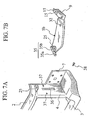
- FIG. 7A is a view showing a radiator
core support panel 1 before coupling a pedestal member thereto in the sixth embodiment of the present invention; - FIG 7B is a view showing the pedestal member before coupled to the radiator core support panel in the sixth embodiment of the present invention;
- FIG 8 is a perspective view showing a state in the course of coupling the pedestal member of FIG. 7B to the radiator core support panel of FIG 7A;
- FIG. 9 is a perspective view showing a state in the course of coupling the pedestal member of FIG 7B to the radiator core support panel of FIG. 7A subsequently to the state of FIG. 8; and
- FIG. 10A and FIG. 10B are schematic cross-sectional views of a head-lamp unit successively showing a head-lamp unit attaching process in the corresponding embodiment of the present invention.
-
- There will be explained hereinafter the embodiments of the present invention with reference to the accompanying drawings, so as to describe the present invention in more detail. In the following description, those identical elements are designated by the same reference numerals, respectively, and the detailed explanation thereof shall be duly simplified or omitted.
- In FIG. 1,
reference numeral 1 designates a radiator core support panel made of a plastic material and constituting a frontmost part of a vehicular body (i.e., front end of vehicular body), and thispanel 1 comprises: anupper rail 2 and afirst cross-member 3 arranged one above the other, and both extending in a vehicular widthwise direction;pillar portions 4 for interconnecting theupper rail 2 andfirst cross-member 3 at both vehicular widthwise sides thereof, respectively; andside portions 5 bulgedly provided at the vehicular widthwise outsides of thepillar portions 4, respectively, so as to mount head-lamp units 6 onto theside portions 5 themselves, respectively. - Each
side portion 5 comprises anupper frame 5a formed integrally with and as an extension of theupper rail 2, alower frame 5b laterally bulged from and provided integrally with thepillar portion 4, and aside frame 5c for interconnecting theupper frame 5a andlower frame 5b, such that eachside portion 5 is bently formed toward a rearward direction of the vehicular body from theupper rail 2 andpillar portion 4. - Each interconnecting portion between the
first cross-member 3 andpillar portion 4 has a vehicular widthwise outer comer portion integrally formed with afastening seat portion 7. - The radiator
core support panel 1 constitutes a front end portion of the vehicular body, by abutting and bolt-fastening eachfastening seat portion 7 to a front end of an associated front side member SB acting as a frame member extending in a vehicular fore-and-aft direction joined to and arranged under a lower side of a hood ridge panel (not shown), by fastening by a bolt 17 a rear end portion of theupper frame 5a of eachside portion 5 as the extension of theupper rail 2 to a front end portion of anupper flange 8a of an associatedfront fender 8 joined and fixed to an upper edge of the hood ridge panel, and by fastening eachlower frame 5b to a front end portion of alower flange 8b of thefront fender 8 by abolt 18 through aseat portion 9 formed integrally with a rear outside of thelower frame 5b. - Each head-
lamp unit 6 is made into a movable structure positionally adjustable to the front end of the associatedfront fender 8. - In this embodiment, each head-
lamp unit 6 is made into the movable structure positionally adjustable to the front end of the associatedfront fender 8, by dividing the radiatorcore support panel 1 into an upper member 1U and alower member 1L one above the other at vertical intermediate portions of thepillar portions 4, respectively, and by coupling the upper member 1U to thelower member 1L pivotably in the vehicular fore-and-aft direction, while attaching thelower member 1L to the front side members on the basis of the latter and attaching the head-lamp units 6 to the front ends of thefront fenders 8, respectively, on the basis of the latter. - Concretely, the upper member 1U is integrally formed of the
upper rail 2, upper portions 4a of thepillar portions 4 and theside portions 5 such as by injection molding, while thelower member 1L is integrally formed of thefirst cross-member 3,lower portions 4b of thepillar portions 4, and thefastening seat portions 7 such as by injection molding. - The upper portion 4a of each
pillar portion 4 has a rearwardly opened channel-like "C" shape cross section at least at its lower end, and this lower end of each upper portion 4a is fitted onto an upper end of the associatedlower portion 4b in such a manner that the upper end of the associatedlower portion 4b is positioned inside the lower end of each upper portion 4a. In this state, the lower end of each upper portion 4a and the upper end of the associatedlower portion 4b are coupled together bypins 10 provided in the vehicular widthwise direction, so that the upper member 1U andlower member 1L are pivotable to each other in the vehicular fore-and-aft direction. - In this embodiment, each head-
lamp unit 6 is firmly fastened to the associatedupper frame 5a andlower frame 5b bybolts 16 through upper and lower bracket pieces 11 (lower bracket pieces are not shown), respectively, such that a bolt through-hole 12 at the rear end portion of eachupper frame 5a to be fastened to the front end portion of the associatedfront fender 8 is established as a so-called clearance hole having a diameter larger than that of thebolt 17, thereby enabling to compensate for a deviation upon attaching adjustment. - In this embodiment, laterally formed across the upper portions 4a of the right and
left pillar portions 4 and up to around thelower frames 5b ofside portions 5 is anarmature portion 13a of afront bumper 13, integrally with theportions 4 andframes 5b. Vertically formed across vehicular widthwise central portions of theupper rail 2 andarmature portion 13a is a hood lock stay 14 integrally with these central portions. - The radiator
core support panel 1 having such a constitution is delivered into a vehicular body assembling line by previously fastening and fixing the head-lamp units 6 to theside portions 5 of the upper member 1U, respectively, viabracket pieces 11 as described above, and is abutted to and coupled to a front body of a vehicle from the front thereof in the vehicular body assembling line. - Concretely, the
fastening seat portions 7 of thelower member 1L are abutted to the front ends of the front side members, respectively, and bolt-fastened to the front side members on the basis of the same. - Then, the upper member 1U is pivoted in the vehicular fore-and-aft direction about the
pins 10, and the head-lamp units 6 are positionally adjusted relative to the front ends of thefront fenders 8 so as to align the peripheries of the head-lamp units 6 with the peripheries of front ends of thefront fenders 8, respectively. Thereafter, theouter seat portions 9 of thelower frames 5b of theside portions 5 are overlapped with lower surfaces of front end portions of thelower flanges 8b of thefront fenders 8 and fastened thereto by thebolts 18, respectively, and the rear end portions of theupper frames 5a are overlapped with front end portions of theupper flanges 8a of thefront fenders 8 and fastened thereto by thebolts 17, respectively, to thereby attach the upper member 1U to the front end portions of thefront fenders 8 on the basis of the latter. - At this time, those deviations of the rear end portions of the
upper frames 5a from theupper flanges 8a of thefront fenders 8 which are accompanying to the positional adjustment of the head-lamp units 6 are compensated for by the bolt through-holes 12 as clearance holes, respectively. - According to the structure of this embodiment as described above, the head-
lamp units 6 can be positionally adjusted to and attached to thefront fenders 8 on the basis of the latter, respectively, thereby allowing to exemplarily uniformalize the clearances and offset-amounts in parting portions between the head-lamp units 6 and the front ends of thefront fenders 8, respectively, to thereby further improve the external appearance. - Particularly, in this embodiment, the head-
lamp units 6 are made into movable structures relative to thefront fenders 8 such that the head-lamp units 6 can be positionally adjusted relative to the front ends of thefront fenders 8, respectively, by dividing the radiatorcore support panel 1 into the upper member 1U andlower member 1L one above the other in which the upper member 1U has theside portions 5 mounted with the head-lamp units 6, respectively, and by coupling the upper member 1U andlower member 1L to each other pivotably in the vehicular fore-and-aft direction. This enables to deal with a situation for changing a vehicular body design while commonizing a platform, by modifying a formation-related upper member 1U of a radiatorcore support panel 1, thereby allowing to exemplarily achieve a reduced cost and an improved development efficiency. - Further, since the upper member 1U is formed integrally with the
armature portion 13a of thefront bumper 13 which is to be attached with a bumper facer (not shown), the head-lamp units 6 andfront bumper 13 are allowed to be integrally made into the movable structure. Thus, adjustingly attaching the head-lamp units 6 to thefront bumper 13 in a sub-assembly step makes it unnecessary to adjust clearances and the like between the head-lamp units 6 andfront bumper 13 after mounting of the radiatorcore support panel 1 in a vehicular body assembling line, thereby enabling to improve an attaching operability. - FIG 2 shows a second embodiment of the present invention including a radiator
core support panel 1 divided into: a main portion 1M comprising anupper rail 2, afirst cross-member 3,pillar portions 4, fasteningseat portions 7, and ahood lock stay 14, which are formed integrally with one another such as by injection molding; andside portions 5 integrally formed themselves such as by injection molding, and coupled to the main portion 1M pivotably in the vehicular widthwise direction and slidably in the vehicular fore-and-aft direction. - In this embodiment, the hood lock stay 14 is vertically formed across and integrally with vehicular widthwise central portions of the
upper rail 2 andfirst cross-member 3. - The main portion 1M is integrally formed with a pair of upper and lower
bracket supporting seats 21 at an upper side surface of eachpillar portion 4, while eachside portion 5 has acoupling base 5d positioned at a vehicular widthwise inside of theside portion 5 itself and provided with a pair of upper andlower brackets 22, such that thesebrackets 22 are coupled to thebracket supporting seats 21 viapins 23, respectively, so that eachside portion 5 is mounted pivotably in the vehicular widthwise direction. - The
brackets 22 have pin through-holes 24 formed as fore-and-aft elongated holes, respectively, and these elongated holes allow the associatedside portion 5 to be slidable in the vehicular fore-and-aft direction relative to the main portion 1M. - Identically to the first embodiment, each head-
lamp unit 6 is previously fastened to anupper frame 5a and alower frame 5b of the associatedside portion 5 bybolts 16 viabracket pieces 11, respectively. - In this second embodiment, the main portion 1M of the radiator
core support panel 1 is bolt-fastened to front side members on the basis of the latter, by abutting thefastening seat portions 7 of the main portion 1M to the front ends of the front side members, respectively. - Then, each
side portion 5 is pivoted in the vehicular widthwise direction about the associatedpin 23 and slid in the vehicular fore-and-aft direction within the elongated range of the pin through-holes 24 of the associatedbrackets 22, so as to positionally adjust the associated head-lamp unit 6 relative to the front end of an associatedfront fender 8, thereby aligning the periphery of the head-lamp unit 6 with the front end periphery of thefront fender 8. - The alignment of the periphery of each head-
lamp unit 6 with the front end periphery of the associatedfront fender 8 directly leads to the alignment of a bolt through-hole 12 at the rear end portion of theupper frame 5a with a bolt through-hole 12a at a front end portion of anupper flange 8a of thefront fender 8, and leads to the alignment of a due bolt through-hole 15 of aseat portion 9 of thelower frame 5b with a bolt through-hole 15a at the front end portion of alower flange 8b of thefront fender 8. Thus, eachside portion 5 is attached and bolt-fastened to the front end portion of the associatedfront fender 8 on the basis of this front end portion by insertingbolts lamp unit 6 andfront fender 8. - To this end, the bolt through-
hole 12 at the rear end portion of eachupper frame 5a is formed not into a clearance hole but into a hole having a diameter fitted to the outer diameter of the associatedbolt 17, in this embodiment. - In this way, the structure of the second embodiment makes the
side portions 5 of the radiatorcore support panel 1 into movable structures in which theseside portions 5 are moved and adjusted to allow the right and left head-lamp units 6 to be independently and positionally adjusted correspondingly to the front ends of the right and leftfront fenders 8, respectively, thereby enabling to enhance the aligning qualities of the head-lamp units 6 with the front ends of thefront fenders 8, respectively. - FIG 3 shows a third embodiment of the present invention including a radiator
core support panel 1 integrally formed of anupper rail 2, afirst cross-member 3,pillar portions 4,side portions 5, fasteningseat portions 7 and a hood lock stay 14 such as by injection molding, and eachside portion 5 is movably mounted with a head-lamp unit 6. - Also in this embodiment, the hood lock stay 14 is vertically formed across and integrally with vehicular widthwise central portions of the
upper rail 2 andfirst cross-member 3. - Each
side portion 5 comprises anupper frame 5a and alower frame 5b having forming bases at vehicular widthwise insides thereof integrally formed withbracket supporting seats 25, respectively, while each head-lamp unit 6 includes a vehicular widthwise inside portion protrudedly provided with a pair of upper andlower brackets 26, such that thesebrackets 26 are coupled to thebracket supporting seats 25 viapins 27, respectively, thereby mounting each head-lamp unit 6 to the associatedside portion 5 pivotably in the vehicular widthwise direction. - The
brackets 26 include pin through-holes 28 formed as fore-and-aft elongated holes, respectively, and these elongated holes allow the associated head-lamp unit 6 to be slidable in the vehicular fore-and-aft direction relative to the associatedside portion 5. - Further, provided at an upper edge portion of a vehicular widthwise outside portion of each head-
lamp unit 6 is abracket piece 11A as a coupling portion for the associatedfront fender 8, and formed at the front end portion of anupper flange 8a of eachfront fender 8 is a bolt through-hole 12a as well as a bolt through-hole 29a adjacent to a front side of the bolt through-hole 12a, such that thebracket piece 11A is bolt-fastened directly to the associatedupper flange 8a by aligning a bolt through-hole 29 of thebracket piece 11A with the bolt through-hole 29a of theupper flange 8a and by inserting abolt 16 through these bolt through-holes. - In this embodiment, the lower one of the pair of upper and
lower brackets lamp unit 6 is formed with a settinghole 31 as an attaching point of a bumper facer (not shown) of a front bumper, so that the bumper facer is attached via setting holes 31. - In this third embodiment, the radiator
core support panel 1 is bolt-fastened to the front side members by abutting thefastening seat portions 7 to the front ends of the front side members, respectively, and the rear end portions of theupper frames 5a of theside portions 5 are overlapped with upper surfaces of theupper flanges 8a and theseat portions 9 oflower frames 5b are overlapped with lower surfaces oflower flanges 8b of thefront fenders 8 and fastened by thebolts core support panel 1 is attached to the front side members andfront fenders 8 on the basis of these members and fenders. - Further, each head-
lamp unit 6 is pivoted in the vehicular widthwise direction about the associatedpin 27 and is slid in the vehicular fore-and-aft direction within the elongated range of the pin through-holes 28 of the associatedbrackets 26, and the head-lamp unit 6 is positionally adjusted relative to the front end of the associatedfront fender 8, thereby aligning the periphery of the head-lamp unit 6 with the front end periphery of thefront fender 8. - The alignment of the periphery of the head-
lamp unit 6 with the front end periphery of the associatedfront fender 8 directly leads to the alignment of the bolt through-hole 29 of thebracket piece 11A provided at the upper edge of the vehicular widthwise outside portion of the head-lamp unit 6 with the bolt through-hole 29a of theupper flange 8a of thefront fender 8, so that the head-lamp unit 6 can be attached and bolt-fastened to the front end portion of thefront fender 8 on the basis of the latter by inserting thebolt 16 through these bolt through-holes - Further, in this embodiment, the bumper facer of the front bumper is previously attached to the attaching
points 31 of thebrackets 26 of the head-lamp units 6, thereby exemplarily excluding the necessity of clearance adjustment between the bumper facer and the head-lamp units 6, to thereby improve the attaching operability. - FIG. 4 shows a fourth embodiment of the present invention, which omits the
upper frame 5a andside frame 5c of theside portion 5 in the third embodiment, while the upper coupling point and lower coupling point of the radiatorcore support panel 1 relative to the associatedfront fender 8 are constituted of aseat portion 9 of alower frame 5b and abracket piece 11A provided at a vehicular widthwise outside portion of each head-lamp unit 6, so that the head-lamp unit 6 also acts as upper coupling means of the radiatorcore support panel 1 to thefront fender 8. - This embodiment includes a bumper facer of a type different from that in the third embodiment, so that each head-
lamp unit 6 includes anupper bracket 26 provided with a settinghole 31 by which the bumper facer is attached. - Thus, the structure of the fourth embodiment allows to obtain the same effect as the third embodiment. Further, since each head-
lamp unit 6 also acts as the upper coupling means of the radiatorcore support panel 1 to thefront fender 8 as described above, theupper frame 5a andside frame 5c of the associatedside portion 5 can be omitted, thereby allowing to simplify the structure of the radiatorcore support panel 1. - Furthermore, since the
upper frame 5a andside frame 5c of eachside portion 5 can be omitted, the formation of eachside portion 5 is liberated from the formation of the associated head-lamp unit 6, thereby enabling to readily deal with the formation difference of the head-lamp unit 6 and to standardize and commonize the radiatorcore support panel 1. - FIG 5 shows a fifth embodiment of the present invention, which effectively utilizes the
lower frame 5b of eachside portion 5 in the fourth embodiment shown in FIG 4 as a pedestal member for supporting the associated head-lamp unit 6 in a manner to temporarily fix the head-lamp unit 6 onto thepedestal member 5b. - Each
pedestal member 5b includes aseat portion 9 at its vehicular widthwise outer end and is formed with a bolt through-hole 32 near theseat portion 9, while the associated head-lamp unit 6 includes a lower surface protrudedly provided with atemporary holding bracket 33 at a position corresponding to the bolt through-hole 32. - Further, each head-
lamp unit 6 is temporarily fixed onto the associatedpedestal member 5b by fastening abolt 34 to thetemporary holding bracket 33 through the bolt through-hole 32 of thepedestal member 5b, after the head-lamp unit 6 is mounted to theside portion 5 pivotably in the vehicular widthwise direction by coupling abracket 26 of the head-lamp unit 6 to abracket supporting seat 25 of theside portion 5 as described above. - In the fifth embodiment, before the radiator
core support panel 1 is abutted and bolt-fastened to front ends of front side members or after such bolt-fastening, eachbolt 34 is unthreaded to release the temporary fixation and to enable to move the head-lamp unit 6, and then the above described aligning adjustment of each head-lamp unit 6 to the associatedfront fender 8 is conducted to thereby fasten and attach thebracket piece 11A andseat portion 9 to thefront fender 8. - Thus, the fifth embodiment allows to obtain the same effect as the fourth embodiment. Further, each head-
lamp unit 6 is temporarily fixed to the associatedpedestal member 5b to enable to restrict the free movement of the head-lamp unit 6 and to prevent an unstable state when thebracket piece 11 and head-lamp units 6 in the state of a sub-assembly are transported to a vehicular body assembling line, thereby allowing to avoid an occurrence of defects such as breakage due to the free movement of the head-lamp units 6 during transportation, and allowing to stably hold the head-lamp units 6 at an initial stage of mounting the radiatorcore support panel 1 to a front body of a vehicle, thereby enabling to improve the mounting operability. - FIGS. 6 through 9 show a sixth embodiment of the present invention, in which the pedestal member (
lower frame 5b of each side portion 5) in the fifth embodiment shown in FIG. 5 is formed separately from the radiatorcore support panel 1. - The vehicular widthwise inner end of each
pedestal member 5b is integrally formed with the lower one of the pair of upper and lowerbracket supporting seats 25 in the fourth embodiment and fifth embodiment, and thepedestal member 5b has its distal portion protrudedly provided with abracket 35 in a "T" shape in plan view. - Meanwhile, each
pillar portion 4 of the radiatorcore support panel 1 is formed with a vertically elongated slit 36 through which the associated "T"shape bracket 35 is insertable such that thepedestal member 5b is rotatable by aneck portion 35b of a fixingportion 35a of thebracket 35, and thepillar portion 4 is formed with attachingholes 37 at required height positions forwardly and rearwardly of theslit 36, respectively. - As shown in FIG 8, each
pedestal member 5b is vertically oriented and its "T"shape bracket 35 is inserted into the associated slit 36, and then thepedestal member 5b is rotated into a substantially horizontal normal state about theneck portion 35b as shown in FIG 9. In this state, the fixingportion 35a of the "T"shape bracket 35 is engaged with and restrained by an inner surface of thepillar portion 4, so that thepedestal member 5b can be attached to the radiatorcore support panel 1 by sliding thepedestal member 5b along theslit 36 up to a required certain height position where the attachingholes 37 are located, and by thereafter fastening and fixing thebracket 35 to thepillar portion 4 bybolts 38 through the attachingholes 37, respectively. - Thus, the structure of the sixth embodiment allows to obtain the same effect as the fifth embodiment. Further, since the laterally protruded
pedestal members 5b are absent upon injection molding the radiatorcore support panel 1, the forming performance can be of course improved, while the outer package shape of the radiatorcore support panel 1 can be downsized upon transporting the same at a stage before the head-lamp units 6 are mounted to thepanel 1 into a state of a sub-assembly, thereby allowing to improve the transporting performance of thepanel 1. - Meantime, in the embodiments shown in FIGS. 2, 3, 4, 5 and 6, the pivot center point of each head-
lamp unit 6, i.e., the position of the associatedpin lamp unit 6, so that the moving direction of a vehicular widthwise outer edge portion of the head-lamp unit 6 becomes linear, thereby enabling to facilitate to compensate for errors of the head-lamp unit 6 relative to the front end of the associatedfront fender 8. - Additionally, in the embodiments shown in FIGS. 2, 3, 4, 5 and 6, each head-
lamp unit 6 may be previously pivoted toward a vehicular widthwise inside about the associatedpin core support panel 1 to the front side members andfront fenders 8. This enables to avoid interference of each head-lamp unit 6 with the associatedfront fender 8 upon abutting the radiatorcore support panel 1 to the front ends of the front side members from the vehicular front, and enables to pivot the head-lamp unit 6 toward the vehicular widthwise outside about thepin - According to the present invention as described above, the head-lamp units disposed at both vehicular widthwise sides of the radiator core support panel, respectively, are made into the movable structures positionally adjustable to the front fenders, thereby allowing to attach the head-lamp units to the front fenders on the basis of the latter, respectively, and to uniformalize clearances, offset-amounts and the like in parting portions between the head-lamp units and the front ends of the front fenders, respectively. There can be thus expected a broader applicable scope of the present invention, in addition to the time of assembling a vehicle.
Claims (10)
- A front body structure of a vehicle, comprising:wherein said radiator core support panel is coupled to front fenders and front side members,a radiator core support panel; andhead-lamp units mounted at both vehicular widthwise sides of said radiator core support panel, respectively,
and wherein said head-lamp units are made into movable structures positionally adjustable to said front fenders, respectively. - The front body structure of a vehicle according to claim 1, wherein said radiator core support panel is divided into an upper member and a lower member, said upper member having both vehicular widthwise sides mounted with said head-lamp units, respectively, and said lower member being coupled to front ends of said front side members,
and wherein said upper member and said lower member are coupled to each other pivotably in a vehicular fore-and-aft direction. - The front body structure of a vehicle according to claim 2, further comprising a front bumper mounted to said upper member.
- The front body structure of a vehicle according to claim 1, wherein said radiator core support panel comprises a main portion and side portions at both vehicular widthwise sides of said main portion,
wherein said side portions are constituted dividedly from said main portion and mounted with said head-lamp units, respectively,
and wherein said side portions are coupled to said main portion pivotably in the vehicular widthwise direction and slidably in the vehicular fore-and-aft direction. - The front body structure of a vehicle according to claim 1, wherein said head-lamp units include vehicular widthwise inside portions, respectively, coupled to said radiator core support panel, pivotably in the vehicular widthwise direction and slidably in the vehicular fore-and-aft direction,
and wherein said head-lamp units include vehicular widthwise outside portions provided with coupling portions to said front fenders, respectively. - The front body structure of a vehicle according to 5, wherein said coupling portions of said head-lamp units at the vehicular widthwise inside portions thereof to said radiator core support panel are provided with attaching points, respectively, for a bumper facer of a front bumper.
- The front body structure of a vehicle according to 5, further comprising upper coupling points and lower coupling points of said radiator core support panel to said front fenders,
wherein said upper coupling points are provided at vehicular widthwise outside portions of said head-lamp units, respectively. - An assembling method of a front body of a vehicle, comprising:coupling a radiator core support panel to front end portions of front side members;moving head-lamp units mounted on the radiator core support panel relative to front fenders, to thereby aligningly adjust the head-lamp units to the front fenders, respectively; andcoupling the radiator core support panel to the front fenders.
- An assembling method of a front body of a vehicle, comprising:releasing temporary fixation of head-lamp units to thereby render the head-lamp units movable, the head-lamp units having been mounted on both vehicular widthwise sides of a radiator core support panel in a manner pivotable toward vehicular widthwise insides about vehicular widthwise inner coupling points of the head-lamp units and having been temporarily fixed to pedestal members provided at both vehicular widthwise sides of the radiator core support panel, respectively;coupling the radiator core support panel to front end portions of front side members;moving the head-lamp units toward front fenders with pivotal movements of the head-lamp units about the coupling points to thereby aligningly adjust the head-lamp units to the front fenders, respectively; andcoupling the radiator core support panel together with the head-lamp units, to the front fenders.
- An assembling method of a front body of a vehicle, comprising:pivoting head-lamp units mounted on both vehicular widthwise sides of a radiator core support panel toward vehicular widthwise insides about vehicular widthwise inner coupling points of the head-lamp units, respectively;abutting and coupling the radiator core support panel to front ends of front side members from the vehicular front, to thereby arrange the head-lamp units at positions inside the front fenders, respectively;moving the head-lamp units toward front fenders with pivotal movements of the head-lamp units about the coupling points to thereby aligningly adjust the head-lamp units to the front fenders, respectively; andcoupling the radiator core support panel together with the head-lamp units, to the front fenders.
Applications Claiming Priority (3)
| Application Number | Priority Date | Filing Date | Title |
|---|---|---|---|
| JP2002055890 | 2002-03-01 | ||
| JP2002055890A JP3891007B2 (en) | 2001-04-23 | 2002-03-01 | Front body structure of automobile and assembly method of front body |
| PCT/JP2002/008090 WO2003074347A1 (en) | 2002-03-01 | 2002-08-07 | Automobile car body front construction and method of assembling car body front |
Publications (2)
| Publication Number | Publication Date |
|---|---|
| EP1481878A1 true EP1481878A1 (en) | 2004-12-01 |
| EP1481878A4 EP1481878A4 (en) | 2007-09-26 |
Family
ID=27784623
Family Applications (1)
| Application Number | Title | Priority Date | Filing Date |
|---|---|---|---|
| EP02760580A Withdrawn EP1481878A4 (en) | 2002-03-01 | 2002-08-07 | Automobile car body front construction and method of assembling car body front |
Country Status (5)
| Country | Link |
|---|---|
| US (1) | US6923495B2 (en) |
| EP (1) | EP1481878A4 (en) |
| CN (1) | CN1520365A (en) |
| AU (1) | AU2002327370A1 (en) |
| WO (1) | WO2003074347A1 (en) |
Cited By (22)
| Publication number | Priority date | Publication date | Assignee | Title |
|---|---|---|---|---|
| FR2873652A1 (en) * | 2004-08-02 | 2006-02-03 | Faurecia Bloc Avant | Front part assembly for motor vehicle, has flexible brackets, each with one end to fix bumper skin and another end connected to front part of vehicle body`s wing, and horizontal reinforcement to connect skin fixing ends of brackets together |
| WO2006058865A1 (en) * | 2004-11-29 | 2006-06-08 | Faurecia Kunststoffe Automobilsysteme Gmbh | Carrier for the front unit of a motor vehicle and method for the mounting thereof |
| EP1595770A3 (en) * | 2004-05-11 | 2006-10-18 | Dr.Ing. h.c.F. Porsche Aktiengesellschaft | Vehicle exhibiting a light source retainer for an external light source |
| EP1854705A1 (en) * | 2006-05-10 | 2007-11-14 | Mazda Motor Corporation | Vehicle body structure |
| EP1932749A1 (en) | 2006-12-13 | 2008-06-18 | Volkswagen Aktiengesellschaft | End module, in particular front end module for a vehicle and method for assembling a front end module to the bodywork of a vehicle |
| FR2921333A1 (en) * | 2007-09-25 | 2009-03-27 | Peugeot Citroen Automobiles Sa | MOTOR VEHICLE WITH REDUCED GAMES AND AFFLEMENTS |
| EP2052950A3 (en) * | 2007-10-26 | 2009-05-27 | Nissan Motor Co., Ltd. | Front structure of a vehicle body |
| WO2009112113A1 (en) * | 2008-03-13 | 2009-09-17 | Daimler Ag | Device for aligning a vehicle component, and corresponding assembly method |
| FR2939396A1 (en) * | 2008-12-09 | 2010-06-11 | Faurecia Bloc Avant | Bumper skin connecting device for body panel of motor vehicle, has strut flange extended towards interior of vehicle from upper end of interior strut, and comprising fixation units for fixing strut flange to body panel |
| DE102009001038A1 (en) * | 2009-02-20 | 2010-09-02 | Faurecia Kunststoffe Automobilsysteme Gmbh | Motor vehicle front unit |
| CN101070078B (en) * | 2006-05-10 | 2011-07-27 | 马自达汽车株式会社 | Vehicle body structure |
| DE102010021567A1 (en) * | 2010-05-26 | 2011-12-01 | Gm Global Technology Operations Llc (N.D.Ges.D. Staates Delaware) | Headlight arrangement for motor vehicle, has illuminating medium with headlight casing and with carrier structure |
| FR2970920A1 (en) * | 2011-01-31 | 2012-08-03 | Peugeot Citroen Automobiles Sa | Bumper assembly for rear part or front part of motor vehicle, has positioning device fixed on supports and arranged to position bumper skin relative to optical unit, where positioning device bears part of optical unit |
| WO2013014154A1 (en) * | 2011-07-26 | 2013-01-31 | Valeo Systemes Thermiques | Front-end module for a motor vehicle |
| GB2495595A (en) * | 2011-10-11 | 2013-04-17 | Gm Global Tech Operations Inc | Headlight assembly pivotally mounted to a vehicle |
| WO2015052343A1 (en) * | 2013-10-11 | 2015-04-16 | Bayerische Motoren Werke Aktiengesellschaft | Method for mounting a front-end module and a front headlamp on a body of a passenger car and holding arrangement for holding a front headlamp on a front-end module |
| EP3018005A4 (en) * | 2013-07-02 | 2017-02-08 | Honda Motor Co., Ltd. | Headlight-affixing structure |
| GB2554396A (en) * | 2016-09-26 | 2018-04-04 | Jaguar Land Rover Ltd | Lamp assembly, method of installing a lamp assembly, method of manufacturing sets of lamp assemblies, and a vehicle comprising a lamp assembly |
| GB2559980A (en) * | 2017-02-23 | 2018-08-29 | Jaguar Land Rover Ltd | Motor vehicle lamp fender alignement assembly |
| GB2560929A (en) * | 2017-03-28 | 2018-10-03 | Jaguar Land Rover Ltd | A bracket for mounting a lamp housing to a motor vehicle |
| FR3095384A1 (en) * | 2019-04-23 | 2020-10-30 | Psa Automobiles Sa | Indexing and supporting element of a motor vehicle shock absorber front bumper in the environment of glassless headlamps |
| EP4026758A1 (en) * | 2021-01-08 | 2022-07-13 | Nio Technology (Anhui) Co., Ltd | Vehicle headlamp mounting assembly and vehicle |
Families Citing this family (58)
| Publication number | Priority date | Publication date | Assignee | Title |
|---|---|---|---|---|
| DE10259903A1 (en) * | 2002-12-20 | 2004-08-26 | Sms Demag Ag | Scissors for cross cutting heavy plate with an eccentric drive |
| FR2855800B1 (en) | 2003-06-06 | 2006-01-13 | Plastic Omnium Cie | OPTICAL BLOCK RECEPTION STRUCTURE, BODY COMPONENT CAPABLE OF RECEIVING AN OPTICAL BLOCK, AND EXTERNAL MODULE COMPRISING A CAR BODY COMPONENT AND AN OPTICAL BLOCK |
| JP3843968B2 (en) * | 2003-06-24 | 2006-11-08 | 日産自動車株式会社 | Headlamp body positioning method and body positioning structure |
| FR2858290B1 (en) * | 2003-07-30 | 2005-10-28 | Faurecia Ind | MOTOR VEHICLE FRONT BLOCK ASSEMBLY INCLUDING MEANS FOR ADJUSTING THE POSITION OF THE OPTICAL BLOCKS, ADJUSTMENT TOOL PROVIDED FOR THE SAME, AND METHOD OF ASSEMBLING SUCH A FRONT BLOCK |
| JP3917965B2 (en) * | 2003-08-26 | 2007-05-23 | 本田技研工業株式会社 | Body front structure |
| JP3976197B2 (en) * | 2003-10-08 | 2007-09-12 | 本田技研工業株式会社 | Front body structure of automobile |
| KR100535759B1 (en) * | 2003-10-17 | 2005-12-12 | 현대모비스 주식회사 | Structure for reinforcement in front end module carrier |
| FR2864013B1 (en) * | 2003-12-19 | 2006-03-17 | Faurecia Bloc Avant | FRONT CAR PART ASSEMBLY COMPRISING ENHANCED FIXING AND ADJUSTING MEANS IN POSITION, AND MOTOR VEHICLE PROVIDED WITH SUCH AN ASSEMBLY. |
| JP4586477B2 (en) * | 2003-12-22 | 2010-11-24 | マツダ株式会社 | Shroud support structure and assembly method |
| JP4432516B2 (en) * | 2004-02-06 | 2010-03-17 | 日産自動車株式会社 | Body front structure |
| US7278680B2 (en) * | 2004-02-17 | 2007-10-09 | Lanxess Corporation | Structural carrier assembly for a motor vehicle |
| KR100577814B1 (en) * | 2004-05-17 | 2006-05-11 | 현대모비스 주식회사 | Horizontal latch coupling structure of upper panel of automobile front end module |
| JP2005349923A (en) * | 2004-06-09 | 2005-12-22 | Calsonic Kansei Corp | Head lamp and mounting structure of bumper fascia side |
| FR2873649B1 (en) * | 2004-08-02 | 2006-11-24 | Faurecia Bloc Avant | FRONT BLOCK ASSEMBLY OF MOTOR VEHICLE |
| FR2885587B1 (en) * | 2005-05-12 | 2007-08-10 | Plastic Omnium Cie | METHOD FOR CONFORMING A BUMPER SKIN AROUND OPTICAL BLOCKS, REINFORCING BUMPER SKIN AND FRONT BLOCK OF MOTOR VEHICLE |
| FR2888197B1 (en) * | 2005-07-08 | 2007-10-12 | Faurecia Bloc Avant | FRONT BLOCK ASSEMBLY OF A CORRESPONDING MOTOR VEHICLE. |
| JP4471299B2 (en) * | 2005-08-25 | 2010-06-02 | ダイハツ工業株式会社 | Auto body front structure |
| US7625036B2 (en) * | 2006-04-04 | 2009-12-01 | Oakwood Energy Management, Inc. | Multi-sectional modular energy absorber and method for configuring same |
| JP4233053B2 (en) * | 2006-04-27 | 2009-03-04 | 本田技研工業株式会社 | Body front structure |
| CN101085625B (en) * | 2006-06-08 | 2011-05-11 | 马自达汽车株式会社 | Vehicle front structure |
| US20080079288A1 (en) * | 2006-09-28 | 2008-04-03 | Magna International Inc. | Front end module with integral upper frame/crush rail |
| US7374233B2 (en) * | 2006-09-29 | 2008-05-20 | Ford Global Technologies, Llc | Lightweight integral corrosion-resistant front-end structure for a vehicle |
| JP5024653B2 (en) * | 2006-10-02 | 2012-09-12 | スズキ株式会社 | Front bumper |
| FR2910865B1 (en) * | 2006-12-28 | 2009-04-03 | Plastic Omnium Cie | SUPPORT PART FOR A SHOCK ABSORPTION SYSTEM INTENDED TO BE FITTED AT THE END OF A LONGERON OF A MOTOR VEHICLE |
| WO2008109093A1 (en) * | 2007-03-06 | 2008-09-12 | Exxonmobil Research And Engineering Company | Fiber reinforced polypropylene composite front end modules |
| US7789179B2 (en) * | 2007-05-03 | 2010-09-07 | International Truck Intellectual Property Company, Llc | Method of compression molding motor vehicle components and parts made therefrom |
| JP5228686B2 (en) * | 2007-12-07 | 2013-07-03 | 日産自動車株式会社 | Body front structure |
| EP2067690B1 (en) * | 2007-12-07 | 2010-06-02 | Nissan Motor Co., Ltd. | Front structure of vehicle body |
| US7644966B2 (en) * | 2008-02-29 | 2010-01-12 | Nissan Technical Center North America, Inc. | Vehicle bumper fascia retainer |
| JP5078825B2 (en) * | 2008-03-26 | 2012-11-21 | カルソニックカンセイ株式会社 | Radiator core support |
| DE102008026996B4 (en) | 2008-06-05 | 2022-10-20 | Dr. Ing. H.C. F. Porsche Aktiengesellschaft | Assembly for mounting a headlight |
| DE102008029713B4 (en) * | 2008-06-23 | 2023-08-31 | Volkswagen Ag | End module, in particular front-end module, for a motor vehicle |
| US8302717B2 (en) * | 2009-11-09 | 2012-11-06 | Kawasaki Jukogyo Kabushiki Kaisha | Utility vehicle |
| DE102010029787A1 (en) * | 2010-06-08 | 2011-12-08 | Faurecia Kunststoffe Automobilsysteme Gmbh | Front carrier for a motor vehicle |
| DE102010029789A1 (en) * | 2010-06-08 | 2011-12-08 | Faurecia Kunststoffe Automobilsysteme Gmbh | Front carrier for a motor vehicle |
| FR2965771B1 (en) * | 2010-10-12 | 2012-12-28 | Faurecia Bloc Avant | FRONT OR REAR ASSEMBLY OF A MOTOR VEHICLE COMPRISING A FIXING ELEMENT FOR FIXING ELEMENTS TO THE VEHICLE BODY |
| DE102010051366A1 (en) * | 2010-11-13 | 2012-05-16 | Gm Global Technology Operations Llc (N.D.Ges.D. Staates Delaware) | Carrier structure for body front work of motor vehicle, has locking crossbeam provided with retainer for fixing bonnet lock |
| JP5299583B2 (en) * | 2010-11-18 | 2013-09-25 | スズキ株式会社 | Vehicle front structure |
| WO2012114824A1 (en) * | 2011-02-23 | 2012-08-30 | 本田技研工業株式会社 | Structure for front portion of automobile body |
| JP5692187B2 (en) * | 2012-08-30 | 2015-04-01 | トヨタ自動車株式会社 | Body front structure |
| US8746783B2 (en) * | 2012-08-31 | 2014-06-10 | GM Global Technology Operations LLC | Positioning and reinforcement structure for a vehicle |
| US9321495B2 (en) | 2012-08-31 | 2016-04-26 | GM Global Technology Operations LLC | Method of assembling a front end assembly of a vehicle |
| CN103802721B (en) * | 2012-11-06 | 2017-11-21 | 标致雪铁龙(中国)汽车贸易有限公司 | A kind of erecting device and its installation method for automobile front lamp component |
| CN103847616B (en) * | 2012-12-06 | 2018-05-25 | 标致雪铁龙(中国)汽车贸易有限公司 | A kind of fixing device for automobile front lamp component |
| DE102013100915A1 (en) | 2013-01-30 | 2014-07-31 | Hbpo Gmbh | Fastening device and alignment method for attachments of vehicles |
| JP6120149B2 (en) * | 2013-03-22 | 2017-04-26 | スズキ株式会社 | Front body structure of automobile |
| JP6183136B2 (en) * | 2013-10-15 | 2017-08-23 | スズキ株式会社 | Body front structure |
| GB2525227B (en) * | 2014-04-16 | 2016-09-14 | Jaguar Land Rover Ltd | Bumper assembly method and apparatus |
| JP6425012B2 (en) * | 2014-08-11 | 2018-11-21 | 三菱自動車工業株式会社 | Vehicle front structure |
| US9944219B2 (en) * | 2015-11-18 | 2018-04-17 | Ford Global Technologies, Llc | Headlamp module slip plane bracket |
| CN205345051U (en) * | 2016-01-26 | 2016-06-29 | 延锋彼欧(上海)汽车外饰系统有限公司 | Adjustable support |
| US9776675B1 (en) * | 2016-05-18 | 2017-10-03 | GM Global Technology Operations LLC | Vehicle wing with position-maintaining endplates |
| CN110466619B (en) * | 2018-05-11 | 2024-09-03 | 上汽通用五菱汽车股份有限公司 | Back skin installing support |
| CN110949531B (en) * | 2018-09-27 | 2023-10-03 | 宇通客车股份有限公司 | vehicle |
| US10953786B2 (en) * | 2019-08-01 | 2021-03-23 | Ford Global Technologies, Llc | Vehicle with headlamp assembly |
| CN112590942B (en) * | 2020-12-25 | 2021-11-30 | 奇瑞汽车股份有限公司 | Automobile front end support and automobile |
| GB2612573B (en) * | 2021-10-20 | 2024-01-10 | Jaguar Land Rover Ltd | Vehicle front end alignment improvements |
| FR3167120A1 (en) * | 2024-10-09 | 2026-04-10 | Renault S.A.S | MOTOR VEHICLE WING LAYOUT |
Citations (1)
| Publication number | Priority date | Publication date | Assignee | Title |
|---|---|---|---|---|
| DE19946995A1 (en) | 1998-09-30 | 2000-04-13 | Ecia Equip Composants Ind Auto | Front panel of a motor vehicle incorporating head lamps within the assembly |
Family Cites Families (24)
| Publication number | Priority date | Publication date | Assignee | Title |
|---|---|---|---|---|
| JPH048029Y2 (en) * | 1987-02-04 | 1992-03-02 | ||
| US4940281A (en) * | 1987-11-18 | 1990-07-10 | Mazda Motor Corporation | Front body structure of vehicle |
| JPH0272143U (en) * | 1988-11-24 | 1990-06-01 | ||
| JP2946470B2 (en) | 1990-04-26 | 1999-09-06 | キヤノン株式会社 | Encryption coding device |
| JPH04365678A (en) * | 1991-03-28 | 1992-12-17 | Mazda Motor Corp | Vehicle body front part structure of automobile |
| US5429412A (en) * | 1993-08-26 | 1995-07-04 | Chrysler Corporation | Plastic fender retainer arrangement |
| JPH08258744A (en) | 1995-03-24 | 1996-10-08 | Nissan Motor Co Ltd | Car body front structure |
| JP3508483B2 (en) | 1997-06-27 | 2004-03-22 | トヨタ車体株式会社 | Vehicle front structure |
| JP3528900B2 (en) | 1997-07-31 | 2004-05-24 | 三菱自動車工業株式会社 | Automotive lamp mounting equipment |
| FR2787410B1 (en) * | 1998-12-21 | 2001-03-09 | Ecia Equip Composants Ind Auto | FRONT PANEL AND ARRANGEMENT OF THE FRONT PANEL IN A MOTOR VEHICLE |
| IT1307007B1 (en) * | 1999-01-26 | 2001-10-11 | Magneti Marelli Climat Srl | PRE-ASSEMBLED FRONT GROUP FOR VEHICLES. |
| JP3697976B2 (en) * | 1999-03-16 | 2005-09-21 | 日産自動車株式会社 | Front end module mounting structure |
| US6450276B1 (en) * | 1999-07-30 | 2002-09-17 | Valeo Inc. | Modular vehicle front end |
| FR2801026B1 (en) * | 1999-11-15 | 2002-02-15 | Plastic Omnium Cie | AUTOMOTIVE TECHNICAL FRONT PANEL, WITHOUT RADIATOR |
| JP2001158285A (en) * | 1999-12-02 | 2001-06-12 | Toyota Motor Corp | Mounting structure for vehicle lighting |
| FR2805497B1 (en) * | 2000-02-28 | 2002-06-14 | Valeo Thermique Moteur Sa | MOUNTING OF A COOLING RADIATOR ON A FRONT SUPPORT OF A MOTOR VEHICLE |
| JP2001277867A (en) * | 2000-04-03 | 2001-10-10 | Denso Corp | Vehicle front end structure |
| JP4025008B2 (en) * | 2000-11-29 | 2007-12-19 | カルソニックカンセイ株式会社 | Radiator core support structure for vehicles |
| EP1213207B2 (en) * | 2000-12-07 | 2014-11-26 | Calsonic Kansei Corporation | Radiator core support structure for vehicle |
| FR2820706B1 (en) * | 2001-02-15 | 2003-05-16 | Faurecia Ind | FRONT BLOCK ASSEMBLY OF A MOTOR VEHICLE COMPRISING AN IMPROVED DEVICE FOR FIXING THE COMPONENTS, AND VEHICLE PROVIDED WITH SUCH AN ASSEMBLY |
| FR2821130B1 (en) * | 2001-02-16 | 2003-12-12 | Peugeot Citroen Automobiles Sa | CLIP FOR FIXING A BODY ELEMENT ON THE STRUCTURE OF A MOTOR VEHICLE |
| JP3747811B2 (en) * | 2001-06-20 | 2006-02-22 | 日産自動車株式会社 | Assembling the front end module |
| DE60212394T2 (en) * | 2001-07-18 | 2007-06-14 | Decoma International Inc., Concord | COMPONENT SUPPORT UNIT COMPOSED FOR A MOTOR VEHICLE |
| FR2835494B1 (en) * | 2002-02-05 | 2004-07-09 | Plastic Omnium Cie | SIDE SOUND INSULATION PART OF AN ENGINE COMPARTMENT, MUDGUARD FULFILLING THIS FUNCTION AND SIDE MODULE FORMED FROM SUCH A MUDGUARD |
-
2002
- 2002-08-07 WO PCT/JP2002/008090 patent/WO2003074347A1/en not_active Ceased
- 2002-08-07 CN CNA028128028A patent/CN1520365A/en active Pending
- 2002-08-07 AU AU2002327370A patent/AU2002327370A1/en not_active Abandoned
- 2002-08-07 US US10/477,925 patent/US6923495B2/en not_active Expired - Fee Related
- 2002-08-07 EP EP02760580A patent/EP1481878A4/en not_active Withdrawn
Patent Citations (1)
| Publication number | Priority date | Publication date | Assignee | Title |
|---|---|---|---|---|
| DE19946995A1 (en) | 1998-09-30 | 2000-04-13 | Ecia Equip Composants Ind Auto | Front panel of a motor vehicle incorporating head lamps within the assembly |
Cited By (36)
| Publication number | Priority date | Publication date | Assignee | Title |
|---|---|---|---|---|
| EP1595770A3 (en) * | 2004-05-11 | 2006-10-18 | Dr.Ing. h.c.F. Porsche Aktiengesellschaft | Vehicle exhibiting a light source retainer for an external light source |
| US7264388B2 (en) | 2004-05-11 | 2007-09-04 | Dr. Ing. H.C.F. Porsche Aktiengesellschaft | Motor vehicle having an illuminating device receiving system for an exterior illuminating device |
| FR2873652A1 (en) * | 2004-08-02 | 2006-02-03 | Faurecia Bloc Avant | Front part assembly for motor vehicle, has flexible brackets, each with one end to fix bumper skin and another end connected to front part of vehicle body`s wing, and horizontal reinforcement to connect skin fixing ends of brackets together |
| EP1623873A1 (en) * | 2004-08-02 | 2006-02-08 | Faurecia Bloc Avant | Vehicle front body structure |
| WO2006058865A1 (en) * | 2004-11-29 | 2006-06-08 | Faurecia Kunststoffe Automobilsysteme Gmbh | Carrier for the front unit of a motor vehicle and method for the mounting thereof |
| US7651158B2 (en) | 2006-05-10 | 2010-01-26 | Mazda Motor Corporation | Vehicle body structure |
| EP1854705A1 (en) * | 2006-05-10 | 2007-11-14 | Mazda Motor Corporation | Vehicle body structure |
| CN101070078B (en) * | 2006-05-10 | 2011-07-27 | 马自达汽车株式会社 | Vehicle body structure |
| EP1932749A1 (en) | 2006-12-13 | 2008-06-18 | Volkswagen Aktiengesellschaft | End module, in particular front end module for a vehicle and method for assembling a front end module to the bodywork of a vehicle |
| DE102006058857A1 (en) * | 2006-12-13 | 2008-06-19 | Volkswagen Ag | End module, in particular front end module for a vehicle, and method for mounting an end module to a vehicle body |
| FR2921333A1 (en) * | 2007-09-25 | 2009-03-27 | Peugeot Citroen Automobiles Sa | MOTOR VEHICLE WITH REDUCED GAMES AND AFFLEMENTS |
| EP2042413A1 (en) * | 2007-09-25 | 2009-04-01 | Peugeot Citroen Automobiles SA | Automobile with reduced clearance and flushing. |
| EP2052950A3 (en) * | 2007-10-26 | 2009-05-27 | Nissan Motor Co., Ltd. | Front structure of a vehicle body |
| KR101026302B1 (en) * | 2007-10-26 | 2011-03-31 | 닛산 지도우샤 가부시키가이샤 | Body front structure |
| US8007035B2 (en) | 2007-10-26 | 2011-08-30 | Nissan Motor Co., Ltd. | Front structure of a vehicle body |
| WO2009112113A1 (en) * | 2008-03-13 | 2009-09-17 | Daimler Ag | Device for aligning a vehicle component, and corresponding assembly method |
| FR2939396A1 (en) * | 2008-12-09 | 2010-06-11 | Faurecia Bloc Avant | Bumper skin connecting device for body panel of motor vehicle, has strut flange extended towards interior of vehicle from upper end of interior strut, and comprising fixation units for fixing strut flange to body panel |
| DE102009001038A1 (en) * | 2009-02-20 | 2010-09-02 | Faurecia Kunststoffe Automobilsysteme Gmbh | Motor vehicle front unit |
| DE102010021567A1 (en) * | 2010-05-26 | 2011-12-01 | Gm Global Technology Operations Llc (N.D.Ges.D. Staates Delaware) | Headlight arrangement for motor vehicle, has illuminating medium with headlight casing and with carrier structure |
| FR2970920A1 (en) * | 2011-01-31 | 2012-08-03 | Peugeot Citroen Automobiles Sa | Bumper assembly for rear part or front part of motor vehicle, has positioning device fixed on supports and arranged to position bumper skin relative to optical unit, where positioning device bears part of optical unit |
| WO2013014154A1 (en) * | 2011-07-26 | 2013-01-31 | Valeo Systemes Thermiques | Front-end module for a motor vehicle |
| FR2978412A1 (en) * | 2011-07-26 | 2013-02-01 | Valeo Systemes Thermiques | FRONT PANEL MODULE OF MOTOR VEHICLE. |
| CN103946103A (en) * | 2011-07-26 | 2014-07-23 | 法雷奥热系统公司 | Front-end module for a motor vehicle |
| US8998306B2 (en) | 2011-07-26 | 2015-04-07 | Valeo Systemes Thermiques | Front-end module for a motor vehicle |
| GB2495595A (en) * | 2011-10-11 | 2013-04-17 | Gm Global Tech Operations Inc | Headlight assembly pivotally mounted to a vehicle |
| US9718394B2 (en) | 2013-07-02 | 2017-08-01 | Honda Motor Co., Ltd. | Headlight-affixing structure |
| EP3018005A4 (en) * | 2013-07-02 | 2017-02-08 | Honda Motor Co., Ltd. | Headlight-affixing structure |
| WO2015052343A1 (en) * | 2013-10-11 | 2015-04-16 | Bayerische Motoren Werke Aktiengesellschaft | Method for mounting a front-end module and a front headlamp on a body of a passenger car and holding arrangement for holding a front headlamp on a front-end module |
| US10207629B2 (en) | 2013-10-11 | 2019-02-19 | Bayerische Motoren Werke Aktiengesellschaft | Method for mounting a front-end module and a front headlamp on a body of a passenger car and holding arrangement for holding a front headlamp on a front-end module |
| GB2554396A (en) * | 2016-09-26 | 2018-04-04 | Jaguar Land Rover Ltd | Lamp assembly, method of installing a lamp assembly, method of manufacturing sets of lamp assemblies, and a vehicle comprising a lamp assembly |
| GB2554396B (en) * | 2016-09-26 | 2019-05-22 | Jaguar Land Rover Ltd | Lamp assembly, method of installing a lamp assembly, method of manufacturing sets of lamp assemblies, and a vehicle comprising a lamp assembly |
| GB2559980A (en) * | 2017-02-23 | 2018-08-29 | Jaguar Land Rover Ltd | Motor vehicle lamp fender alignement assembly |
| GB2559980B (en) * | 2017-02-23 | 2019-10-30 | Jaguar Land Rover Ltd | Motor vehicle lamp fender alignement assembly |
| GB2560929A (en) * | 2017-03-28 | 2018-10-03 | Jaguar Land Rover Ltd | A bracket for mounting a lamp housing to a motor vehicle |
| FR3095384A1 (en) * | 2019-04-23 | 2020-10-30 | Psa Automobiles Sa | Indexing and supporting element of a motor vehicle shock absorber front bumper in the environment of glassless headlamps |
| EP4026758A1 (en) * | 2021-01-08 | 2022-07-13 | Nio Technology (Anhui) Co., Ltd | Vehicle headlamp mounting assembly and vehicle |
Also Published As
| Publication number | Publication date |
|---|---|
| CN1520365A (en) | 2004-08-11 |
| WO2003074347A1 (en) | 2003-09-12 |
| AU2002327370A1 (en) | 2003-09-16 |
| US20050088015A1 (en) | 2005-04-28 |
| EP1481878A4 (en) | 2007-09-26 |
| US6923495B2 (en) | 2005-08-02 |
Similar Documents
| Publication | Publication Date | Title |
|---|---|---|
| US6923495B2 (en) | Automobile car body front construction and method of assembling car body front | |
| US8636396B2 (en) | Vehicle body front structure | |
| EP1270387B1 (en) | Method for assemblying vehicle body | |
| JP3891007B2 (en) | Front body structure of automobile and assembly method of front body | |
| US7364225B2 (en) | Vehicle body structure | |
| US10207629B2 (en) | Method for mounting a front-end module and a front headlamp on a body of a passenger car and holding arrangement for holding a front headlamp on a front-end module | |
| US7306279B2 (en) | Vehicle rear door and method of assembling same | |
| US7574801B2 (en) | Single set geometry method for assembly of a vehicle | |
| CZ20001431A3 (en) | End module assembly for installation onto a vehicle and process for producing thereof | |
| US7008008B2 (en) | Cross-member at automobile front | |
| EP0980817A2 (en) | Method for manufacturing a rear structure for a motor vehicle | |
| US8308215B2 (en) | Lower structure of vehicle body rear part | |
| US6811199B2 (en) | Bracket construction for seat striker | |
| US7270368B2 (en) | Shroud supporting structure and shroud mounting method | |
| US11292531B2 (en) | Vehicle body joint structure | |
| KR102474386B1 (en) | Joint structure of quarter part for vehicle | |
| US11724587B2 (en) | Radiator support upper member assembly | |
| JP2024033162A (en) | How to assemble the front part of the vehicle | |
| US8523276B2 (en) | Vehicle including a transverse understructure member and a technical front panel pivotably supported by the transverse understructure member during mounting | |
| US8136864B2 (en) | Injection molded magnesium link and method of making an injection molded magnesium link | |
| JP4246415B2 (en) | Vehicle door | |
| JP4048827B2 (en) | Body front part assembly method and assembly jig | |
| JP2999536B2 (en) | How to assemble vehicle parts | |
| JP2994835B2 (en) | How to assemble the instrument panel | |
| JPH081147Y2 (en) | Bumper mounting structure |
Legal Events
| Date | Code | Title | Description |
|---|---|---|---|
| PUAI | Public reference made under article 153(3) epc to a published international application that has entered the european phase |
Free format text: ORIGINAL CODE: 0009012 |
|
| 17P | Request for examination filed |
Effective date: 20031119 |
|
| AK | Designated contracting states |
Kind code of ref document: A1 Designated state(s): AT BE BG CH CY CZ DE DK EE ES FI FR GB GR IE IT LI LU MC NL PT SE SK TR |
|
| AX | Request for extension of the european patent |
Extension state: AL LT LV MK RO SI |
|
| TPAC | Observations filed by third parties |
Free format text: ORIGINAL CODE: EPIDOSNTIPA |
|
| RBV | Designated contracting states (corrected) |
Designated state(s): DE FR GB |
|
| A4 | Supplementary search report drawn up and despatched |
Effective date: 20070823 |
|
| 17Q | First examination report despatched |
Effective date: 20080602 |
|
| STAA | Information on the status of an ep patent application or granted ep patent |
Free format text: STATUS: THE APPLICATION IS DEEMED TO BE WITHDRAWN |
|
| 18D | Application deemed to be withdrawn |
Effective date: 20090924 |