EP1481873A1 - Steer-by-wire system - Google Patents
Steer-by-wire system Download PDFInfo
- Publication number
- EP1481873A1 EP1481873A1 EP20040252787 EP04252787A EP1481873A1 EP 1481873 A1 EP1481873 A1 EP 1481873A1 EP 20040252787 EP20040252787 EP 20040252787 EP 04252787 A EP04252787 A EP 04252787A EP 1481873 A1 EP1481873 A1 EP 1481873A1
- Authority
- EP
- European Patent Office
- Prior art keywords
- steer
- clutch
- cage
- wire system
- receiving space
- Prior art date
- Legal status (The legal status is an assumption and is not a legal conclusion. Google has not performed a legal analysis and makes no representation as to the accuracy of the status listed.)
- Granted
Links
Images


Classifications
-
- F—MECHANICAL ENGINEERING; LIGHTING; HEATING; WEAPONS; BLASTING
- F16—ENGINEERING ELEMENTS AND UNITS; GENERAL MEASURES FOR PRODUCING AND MAINTAINING EFFECTIVE FUNCTIONING OF MACHINES OR INSTALLATIONS; THERMAL INSULATION IN GENERAL
- F16D—COUPLINGS FOR TRANSMITTING ROTATION; CLUTCHES; BRAKES
- F16D41/00—Freewheels or freewheel clutches
- F16D41/06—Freewheels or freewheel clutches with intermediate wedging coupling members between an inner and an outer surface
- F16D41/08—Freewheels or freewheel clutches with intermediate wedging coupling members between an inner and an outer surface with provision for altering the freewheeling action
- F16D41/086—Freewheels or freewheel clutches with intermediate wedging coupling members between an inner and an outer surface with provision for altering the freewheeling action the intermediate members being of circular cross-section and wedging by rolling
-
- B—PERFORMING OPERATIONS; TRANSPORTING
- B62—LAND VEHICLES FOR TRAVELLING OTHERWISE THAN ON RAILS
- B62D—MOTOR VEHICLES; TRAILERS
- B62D5/00—Power-assisted or power-driven steering
- B62D5/001—Mechanical components or aspects of steer-by-wire systems, not otherwise provided for in this maingroup
- B62D5/003—Backup systems, e.g. for manual steering
Definitions
- the clutch can be manually or automatically operated to connect the shaft of the steering wheel to the shaft of the steering gear so as to establish the state in which the steering gear can be steered by the steering wheel.
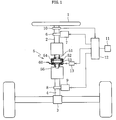
- the first shaft 2 on the steering wheel 1 side has a first motor 7 mounted thereon for transmission of a steering reaction through a gear 6, while the second shaft 4 on the steering gear 3 side has a second motor 9 mounted thereon for transmission of a steering force to the steering gear 3 through a gear 8.
- the clutch 5 has attached thereto a mechanism (for example, a clutch switching actuator 13) for switching the first and second shafts 2 and 4 to a connected or unconnected state timely in response to the state of the system.
- a control mechanism for controlling this steer-by-wire system comprises any of the various sensors, such as a steering angle sensor 10 for detecting the steering angle of the steering wheel 1, an abnormality detection sensor 11 for detecting the abnormality of the system, and a controller (control device) 12.
- the steering angle sensor 10 is disposed, for example, in the first shaft 2, and the abnormality detection sensor 11 is installed, for example, in the first motor 7 and/or the second motor 9.
- the controller 12 delivers control signals to the first and second motors 7 and 9 and clutch switching actuator 13 on the basis of a signal concerning the steering angle detected by the steering angle sensor 10 and abnormality detection signal from the abnormality detection sensor 11.
- the engaging element receiving space 58 gradually narrowing toward axial one side is defined between the taper section 56a of the output shaft 56 and the inner peripheral surface of the clutch member 52, and the taper rollers 53 received in the pockets 54a of the cage 54 are disposed in this engaging element receiving space 58.
- the housing cover 61 is mounted from the diameter-increased side of the taper section 56a of the output shaft 56 with its inner surface 61a opposed to the actuation member 59.
- the inner surface 61a of the housing cover 61 is formed with a wedge projection 61b gradually projecting in a direction opposite to that for the wedge projection 59c of the actuation member 59 (in Fig. 2) , the right-handed direction as the housing cover 61 is looked at from the lower side of the output shaft 56) for meshing with the wedge projection 59c of the actuation member 59.
- the wedge projection 61b formed on the housing cover 61 and the wedge projections 59c formed on the actuation member 59 form a pair of cam mechanism 63 for moving the actuation member 59 axially (in the figure, upwardly).
- the input shaft 51, clutch member 52, actuation member 59, and housing cover 61 can be produced at low cost as by cold press work.
Abstract
Description
- This invention relates to a steer-by-wire system having a fail-safe mechanism designed so that when a defect occurs in the steer-by-wire system, a shaft connected to a steering wheel is connected to a shaft that is connected to a steering gear, so as to make steering possible directly by the steering wheel.
- Though not commercially available at present, development of steer-by-wire systems in which the steering wheel is not mechanically connected to a steering gear is in progress in various places. This has merits, such as the capability of automatically controlling the wheel steering angle by car speed detection and increasing the degree of freedom of car interior layout, and is expected to enable more stabilized vehicle running and to improve driving performance.
- An example of such steer-by-wire systems will be described with reference to Fig. 10. A steer-by-
wire system 100, as shown in Fig. 10, comprises asteering wheel 110, ashaft 120 connected to thesteering wheel 110, asteering gear 130, ashaft 140 connected to thesteering gear 130, areaction simulator 150 mounted on saidshaft 120, asteering actuator 160 mounted on theshaft 140, abackup clutch 170 mounted between theshafts controller 180 for controlling thereaction simulator 150,steering actuator 160, andclutch 170. - This steer-by-
wire system 100 is arranged to timely cancel the connection between thesteering wheel 110 and thesteering gear 130 established by theclutch 170 so as to control the steering angle of thesteering gear 130 by thecontroller 180 through thesteering actuator 160 according to the steering angle of thesteering wheel 110, while making the steering reaction controllable by thereaction simulator 150. - In such steer-by-wire, however, if a defect should occur in the motor or the like (for example, the
steering actuator 160 or reaction simulator 150), a defect sometimes occurs in steering-based vehicle control. As a fail-safe mechanism, it has been proposed to use a solenoid clutch as theclutch 170 to interconnect the steering wheel and the steering gear so as to enable steering directly by the steering wheel. See, for example, Japanese Unexamined Patent Publication 2001-301639. - A solenoid clutch type steer-by-
wire 200 described in the Patent Publication, as shown in Fig. 11, comprises asteering wheel 210, ashaft 220 connected to thesteering wheel 210, asteering gear 230, which is a steering wheel, ashaft 240 connected to thesteering gear 230, asolenoid clutch 250 mounted on theshaft 220, asolenoid clutch 260 mounted on theshaft 240, ashaft 270 connecting thesesolenoid clutches gear 280 mounted on theshaft 270, amotor 290 for driving thegear 280, agear 300 mounted on theshaft 240, amotor 310 for driving thegear 300, asteering angle sensor 320 mounted on theshaft 220, acontroller 330 for controlling thesolenoid clutches motors motors steering angle sensor 320, and acar speed sensor 340 for detecting the car speed to input the latter into thecontroller 330. - The steer-by-
wire system 200 described in the Patent Publication mentioned above usessolenoid clutches solenoid clutches steering wheel 210 and thesteering gear 230 impossible. Further, the use of solenoid clutches has many drawbacks, such as the necessity of securing electric power supply capacity to some extent and the necessity of enlarging the installation space. - Accordingly, an object of the invention is to provide a steer-by-wire system having a fail-safe mechanism, which is less influenced by a malfunction of an electric system and which makes compact construction possible.
- To solve the problem described above, the invention provides a steer-by-wire system comprising a steering wheel, a first shaft connected to the steering wheel, a first motor for transmitting a steering reaction to the first shaft, a steering gear, a second shaft connected to the steering gear, a second motor for transmitting a steering force to the second shaft, and a clutch mounted between the first and second shafts for switching the first and second shafts to a connected state or an unconnected state, wherein the clutch comprises an input member to which the rotation torque of the first shaft is inputted, a driven member connected to the second shaft, an engaging element receiving space defined between the input member and the driven member, an engaging element disposed in the engaging element receiving space and peripherally wedgewise engageable between the input member and the driven member, and an operating means disposed on axial one side of said engaging element receiving space and adapted to axially move the engaging elements to a wedgewise engageable position after the engaging elements have moved to the axial one side of the receiving space, and to a position where the engaging elements become non-engageable as they moves to the axial opposite side, and wherein when a defect occurs in the steer-by-wire system, the engaging element is moved to the wedgewise engageable position in the engaging element receiving space through the operating means to connect the first and second shafts so as to make steering possible by the steering wheel without the intermediary of the steer-by-wire system.
- In the steer-by-wire system according to the invention, even when steering is made impossible as by a motor defect or when supply of power is interrupted, the steering wheel and the steering gear can be interconnected by the clutch, the fail-safe mechanism thus functioning. This clutch, unlike a dog clutch, is capable of connection irrespective of input-output phase difference. Furthermore, as compared with a solenoid clutch, size and weight reduction and cost reduction are possible, and the clutch is also advantageous from the standpoint of energy saving since there is no need to constantly apply power thereto.
- The clutch is arranged such that when the engaging element is moved to the wedgewise engageable position in the engaging element receiving space by the operating means, the driven member concomitantly rotates relative to the input member, thereby connecting the first and second shafts. Further, when the engaging element is moved to the position in the engaging element receiving space where it becomes non-engageable, the driven member stops concomitantly rotating relative to the input member, thereby canceling the connection between the first and second shafts. The use of this clutch makes it possible to achieve size reduction, weight reduction and cost reduction as compared with solenoid clutches, and eliminates the need of constant electric power application, which is advantageous from the standpoint of energy saving. Further, it is also possible to manually cause the fail-safe mechanism to function when a malfunction occurs in the electric system.
- Specifically, in the case where a defect occurs in the steer-by-wire system, the clutch can be manually or automatically operated to connect the shaft of the steering wheel to the shaft of the steering gear so as to establish the state in which the steering gear can be steered by the steering wheel.
- Specifically, the clutch can comprise engaging elements in the form of taper rollers, a cage holding the taper rollers and axially movably disposed between the input member and the driven member, an engaging element receiving space defined such that between the input member and the driven member, it is narrower on one axial side and gradually widens toward the opposite side, the narrower side of the engaging element receiving space having an engaging position where the taper roller is peripherally engageable, the wider side having a canceling position for canceling the wedgelike engagement of the taper roller, the taper roller being disposed with its small diameter end directed to the narrower side of the engaging element receiving space, the operating means being adapted to axially move the taper rollers together with the cage, back and forth.
- In this case, one end of the cage can be formed with a notch allowing peripheral elastic deformation of the cage. Thereby, when inputted rotation torque is transmitted or when the cage is axially relatively moved, the internal stress produced in the cage can be mitigated and breakage of the cage can be prevented.
- Further, a clutch member peripherally engaging either the input member or the driven member can be provided and that the clutch member can be formed with a cam surface peripherally wedgewise engageable by a taper roller. Thus, providing the clutch member, as a separate member, having a profile cam surface wedgewise engageable by a taper roller, facilitates manufacture, such as the forming of a cam surface, making it possible to achieve cost reduction.
- Further, the clutch member can be provided with a guide section for axially guiding the cage. This enables the cage to axially move in a straight line, suppressing the skewing or the like of the taper roller, whereby the cage can be prevented from having unexpected load applied thereto.
- Further, the operating means may be composed of an elastically urging means for urging the taper rollers, together with the cage, to the narrower side of the engaging element receiving space, and an engaged state canceling means for moving the taper rollers, together with the cage, to the wider side of the engaging element receiving space against the elastically urging means to cancel the wedgelike engagement state of the taper rollers.
- In this case, the elastically urging means may be a spring member incorporated between the input member or driven member and one end of the cage on the wider side of the engaging element receiving space. As the spring member, for example, a wave spring member having a wave-shaped cross section may be incorporated, whereby a reliable pressingly urging function can be obtained and size-compaction can be achieved.
- The engaged state canceling means may be composed of an actuation member having a pressing section disposed to be axially opposed to the peripheral edge of the cage on the small end side of the taper rollers, a stationary member that is axially stationary relative to the engaging element receiving space, a cam mechanism that, when the actuation member is rotated in a predetermined direction relative to the stationary member, axially moves the actuation member to pressingly move the taper rollers together with the cage by the pressing section, and an operating section for turnably operating the actuation member.
- The stationary member may have applied thereto a housing that rotatably armors the input member and driven member through bearings.
- Further, an elastic restoration member may be provided for storing elastic force when the actuation member is turned relative to the stationary member and for separating the pressing section of the actuation member from the peripheral edge of the cage on the small diameter end side of the taper rollers when the actuation member is turned in the opposite direction relative to the stationary member.
- The elastic restoration member may be in the form of a coil spring fastened at one end thereof to the actuation member and at the other end to the stationary member. It is recommended that such coil spring be mounted in the housing serving as a stationary member and be fastened at one end thereof to the lever of the actuation member and at the other end to the housing.
- The fail-safe mechanism may comprise an abnormality detection sensor for detecting abnormality in the system, a clutch switching actuator for operating the clutch, and a controller for operating the clutch switching actuator on the basis of an abnormality detection signal from the abnormality detection sensor, it being recommended that when an abnormality detection signal is received front the abnormality detection sensor, the controller operates the clutch to interconnect the first and second shafts through the clutch switching actuator. In this case, as compared with the case of the driver manually operating the clutch after he or she senses abnormality, there will arise no situation in which for example, the driver senses abnormality and gets into a panic, causing delay in switching the clutch; rather, the fail-safe mechanism can function automatically in a short time, and infallibly, so that the safety of the steer-by-wire system can be improved.
-
- Fig. 1 is a schematic diagram of a steer-by-wire system according to an embodiment of the invention;
- Fig. 2 is a side view, in longitudinal section, of an embodied clutch used for the steer-by-wire system of the invention;
- Fig. 3 is an exploded perspective view of a clutch member and a cage in the clutch of Fig. 2;
- Fig. 4 is a principal enlarged cross-sectional view showing a cam surface formed on the clutch member;
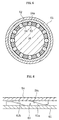
- Fig. 5 is a cross-sectional view showing disposition of taper rollers;
- Fig. 6 is an enlarged front view showing a cam mechanism between an actuation member and a housing;
- Fig. 7 is a bottom view showing the position of an operating lever in an unconnected state;
- Fig. 8A is a principal enlarged longitudinal sectional view showing the positions of the actuation member and a housing cover in an unconnected state;
- Fig. 8B is a principal enlarged longitudinal sectional view showing the positions of the actuation member and the housing cover in a connected state;
- Fig. 9A is a principal enlarged front view showing a state in which the cam mechanism for the actuation member and the housing cover, which are in an unconnected state, is not engaged;
- Fig. 9B is a principal enlarged front view showing a state in which the cam mechanism for the actuation member and the housing cover, which are in a connected state, is engaged;
- Fig. 10 is a schematic diagram of a steer-by-wire system using a conventional clutch; and
- Fig. 11 is a schematic diagram of a steer-by-wire system using a conventional solenoid clutch.
-
- A steer-by-wire system having a fail-safe mechanism according to an embodiment of the invention will now be described with reference to the drawings.
- A steer-by-wire system having a fail-safe mechanism, as shown in Fig. 1, comprises a
steering wheel 1, afirst shaft 2 connected to thesteering wheel 1, asteering gear 3, asecond shaft 4 connected to thesteering gear 3, and amechanical clutch 5 mounted between the first andsecond shafts - The
first shaft 2 on thesteering wheel 1 side has afirst motor 7 mounted thereon for transmission of a steering reaction through agear 6, while thesecond shaft 4 on thesteering gear 3 side has asecond motor 9 mounted thereon for transmission of a steering force to thesteering gear 3 through agear 8. Further, theclutch 5 has attached thereto a mechanism (for example, a clutch switching actuator 13) for switching the first andsecond shafts - A control mechanism for controlling this steer-by-wire system comprises any of the various sensors, such as a
steering angle sensor 10 for detecting the steering angle of thesteering wheel 1, anabnormality detection sensor 11 for detecting the abnormality of the system, and a controller (control device) 12. Thesteering angle sensor 10 is disposed, for example, in thefirst shaft 2, and theabnormality detection sensor 11 is installed, for example, in thefirst motor 7 and/or thesecond motor 9. Thecontroller 12 delivers control signals to the first andsecond motors clutch switching actuator 13 on the basis of a signal concerning the steering angle detected by thesteering angle sensor 10 and abnormality detection signal from theabnormality detection sensor 11. And the clutch 5 is arranged to be timely operated through theclutch switching actuator 13 to interconriect or-disconnect the first andsecond shafts steering wheel 1 side and on thesteering gear 3 side, respectively, and that a reaction force corresponding to the steering angle of thesteering wheel 1 be imparted to thefirst shaft 2 through thefirst motor 7 and thesteering gear 3 is assist-steered through thesecond motor 9 and through thesecond shaft 4. Further, when theabnormality detection sensor 11 detects the abnormality of the steer-by-wire system, thecontroller 12 delivers a control signal to theclutch switching actuator 13 on the basis of an abnormality detection signal from theabnormality detection sensor 11. And the clutch 5 is arranged to be switched through theclutch switching actuator 13 so as to interconnect the first andsecond shafts - The arrangement and operation of the clutch 5 used in this fail-safe mechanism for steer-by-wire systems will be described below.
- The
clutch 5, as shown in Fig. 2, comprises aninput shaft 51 serving as a casing and connected to thefirst shaft 2 to have its rotation torque inputted thereto, aclutch member 52 mounted on the inner peripheral surface of thecylindrical section 51a of theinput shaft 51,taper rollers 53 serving as engaging elements, acage 54 for holding thetaper rollers 53, awave spring 55 serving as an elastic urging means for axially pressing thecage 54, anoutput shaft 56 serving as a driven member connected to thesecond shaft 4, an engagingelement receiving space 58 defined between theclutch member 52 and the output shat 56, and anactuation member 59 serving as an operating means having an operatinglever 60. In addition, Fig. 2 shows a state in which theoutput shaft 56 rotates as driven by theinput shaft 51 and in which the first andsecond shafts - The
clutch member 52, as shown in Fig. 3, is a substantially cylindrical member having an outer diameter capable of being mounted on the inner peripheral surface of thecylindrical section 51a of theinput shaft 51. The peripheral edge of the axial one side of the clutch member 52 (the upper peripheral edge in the figure) is provided with a plurality of axially extending engagingpieces 52a peripherally disposed at predetermined intervals. Further, the inner peripheral surface of theclutch member 52, as shown in Fig. 4, is formed with a plurality of cam surfaces 52b adapted to be engaged by thetaper rollers 53 as will be later described, peripherally disposed at predetermined intervals correspondingly to thepockets 54a of thecage 54. Thiscam surface 52b is shaped such that in order for thetaper roller 53 to engage it in both forward and reverse directions, it is deep in the center, becoming gradually shallower from the center toward both sides as seen in the direction of rotation. - The
cage 54, as shown in Fig. 3, is a substantially cylindrical member having an outer diameter capable of being mounted on the inner peripheral surface of theclutch member 52 and is formed with a plurality ofpockets 54a peripherally disposed at predetermined intervals for receiving thetaper rollers 53. Thiscage 54, as shown in Fig. 5, has, for example, 12pockets 54a peripherally formed at equal intervals. Eachpocket 54a of thecage 54 is adapted to receive thetaper roller 53 with a 0.1 mm or less peripheral clearance or a slight interference and with a 0.2 mm or less axial clearance. In addition, thepocket 54a of thecage 54 is formed, at least on either the outer diameter side or the inner diameter side, with a projection projecting inwardly of thepocket 54a so as to prevent thetaper roller 53 from falling off thepocket 54a. - Further, the
cage 54, as shown in Fig. 3, has a plurality of radially outwardly projectingengaging projections 54b at peripheral predetermined intervals, at one axial end (the upper end in the figure) . The engagingprojections 54b are arranged such that they can be incorporated between the engagingpieces clutch member 52. The engagingprojections 54b and the engagingpieces 52a of theclutch member 52 are peripherally engaged with each other and thecage 54 is incorporated in the inner periphery of theclutch member 52. Further, each engagingprojection 54b is radially formed, at its peripheral center, with anotch 54c. - The
cage 54, as shown in Fig. 3, is incorporated in the inner periphery of theclutch tnember 52 with the engagingpieces 52a of theclutch member 52 engaged with the engagingprojection 54b of thecage 54. Thecage 54 and theclutch member 52, as shown in Fig. 2, are mounted, in their assembled state, in the inner peripheral surface of theinput shaft 51, with the engagingpieces 52a of theclutch member 52 incorporated on the inner surface of thecylindrical section 51a of theinput shaft 51. This enables thecage 54 andclutch member 52 to be attached to theinput shaft 51. - The
clutch member 52 thus incorporated into theinput shaft 51 rotates integrally with theinput shaft 51 because of the engagement of the engagingpieces 52a with the periphery of theinput shaft 51. Further, since the engagingprojections 54b are peripherally engaged with the engagingpieces 52a of theclutch member 52, thecage 54 rotates integrally with theclutch member 52 andinput shaft 51, and can be axially slid as guided by the engagingpieces 52a of theclutch member 52. Thus, the engagingpieces 52a of theclutch member 52 have the function of a guide for axially guiding thecage 54. - In addition, although omitted from illustration, an attaching jig is used in incorporating the
cage 54 into theinput shaft 51 with thetaper rollers 53 attached to thecage 54 Further, in assembling theinput shaft 51,clutch member 52,cage 54 andtaper rollers 53, awave spring 55 is incorporated between theinput shaft 51 and the engagingprojections 54b of thecage 54, as shown in Fig. 2. - The
output shaft 56, as shown in Fig. 2, has an axially diameter-increase taper section 56a on the outer peripheral surface of the intermediate region. The diameter-reduced side (the upper side in the figure) of thetaper section 56a has three level differences to reduce the diameter stepwise. - The assembly of
input shaft 51,clutch member 52,cage 54 andtaper rollers 53 shown in Fig. 2 is mounted on theoutput shaft 56 from the end on the diameter-reduced side of thetaper section 56a. Thewave spring 55 is incorporated in the first level difference section of theoutput shaft 56, the second level difference section is left free, and the third level difference section is rotatably mounted through abearing 57 for rotation relative to theinput shaft 51. - In this state, the engaging
element receiving space 58 gradually narrowing toward axial one side (the lower side in the figure) is defined between thetaper section 56a of theoutput shaft 56 and the inner peripheral surface of theclutch member 52, and thetaper rollers 53 received in thepockets 54a of thecage 54 are disposed in this engagingelement receiving space 58. Thenarrower side 58a of this engagingelement receiving space 58 provides an engaging position where thetaper rollers 53 are allowed to peripherally wedgewise engage the cam surfaces 52b of theclutch member 52, while thewider side 58b of the engagingelement receiving space 58 provides a canceling position where the peripheral wedgelike engagement of thetaper rollers 53 is cancelled, since the spacing between thetaper 56a of theoutput shaft 56 and the inner peripheral surface of theclutch member 52 is wider than the outer diameter of thetaper rollers 53. - The
actuation member 59 is centrally formed with ahole 59a for loose fit on theoutput shaft 56. Theactuation member 59 is mounted on theoutput shaft 56 from the end on the diameter-increased side of thetaper section 56a. The inner diameter end of thehole 59a in theactuation member 59, and its vicinity, serve as apressing section 59b for pressing thecage 54. The opposite surface of the actuation member 59 (the surface not opposed to the cage 54) , as shown in Fig. 6, is formed with a plurality ofwedge projections 59c gradually projecting peripherally (in the figure, the left-handed direction asactuation member 59 is looked at from the lower end side of the output shaft 56). - The
housing cover 61 is a cover member for sealing the open end of the housing (input shaft) 51 armoring the clutch portion, and cooperates with theinput shaft 51 to form the housing. Anopening 62 that peripherally opens is formed between the lower portion of theinput shaft 51 and the upper portion of thehousing cover 61, and the operatinglever 60 of theactuation member 59 extends from theopening 62 until it is outside the housing (input shaft) 51 and thehousing cover 61, so that the operatinglever 60 can be operated for turning. - The
housing cover 61 is mounted from the diameter-increased side of thetaper section 56a of theoutput shaft 56 with itsinner surface 61a opposed to theactuation member 59. Theinner surface 61a of thehousing cover 61, as shown in Fig. 6, is formed with awedge projection 61b gradually projecting in a direction opposite to that for thewedge projection 59c of the actuation member 59 (in Fig. 2) , the right-handed direction as thehousing cover 61 is looked at from the lower side of the output shaft 56) for meshing with thewedge projection 59c of theactuation member 59. Thewedge projection 61b formed on thehousing cover 61 and thewedge projections 59c formed on theactuation member 59 form a pair ofcam mechanism 63 for moving theactuation member 59 axially (in the figure, upwardly). - The housing (input shaft) 51 is rotatably attached to the
output shaft 56 by a bearing 57 installed on the third level difference section of theoutput shaft 56, as described above, and thehousing cover 61, as shown in Fig. 2, is rotatably attached to theoutput shaft 56 through abearing 64 installed between thehousing cover 61 and theoutput shaft 56, and is fastened by a fastening means, for example, crimping by burring. - The
input shaft 51,clutch member 52,actuation member 59, andhousing cover 61 can be produced at low cost as by cold press work. - Next, the operation of this
clutch 5 will be described. Thisclutch 5, as shown in Fig. 7, is arranged such that when the wedgelike engagement of thetaper rollers 53 is cancelled by turning the operatinglever 60 of theactuation member 59 to the left (solid line position) , theinput shaft 51 and theoutput shaft 56 are put in a disconnected state, so that the first andsecond shafts - Specifically, the operating
lever 60, as shown in the left-hand side solid line position of Fig. 7, is turned counterclockwise to a position where thewedge projection 59c of theactuation member 59 and thewedge projection 61b of thehousing cover 61 mesh with each other. Thereby, thewedge projection 59c of theactuation member 59, as shown in Figs. 8A and 9A, move onto thewedge projection 61b of thehousing cover 61 and then axially upward. Thecage 54 is pushed out to thewider side 58b of the engagingelement receiving space 58 by thepressing section 59b of theactuation member 59 against the elastic force of thewave spring 55, and thetaper rollers 53 move together with thecage 54 to thewider side 58b of the engagingelement receiving space 58. When thecage 54 is positioned on thewider side 58b of the engagingelement receiving space 58, the clearance between theoutput shaft 56 and theclutch member 52 is wider, so that the peripheral wedgelike engagement of the taper rollers with the cam surfaces 52b formed in theclutch member 52 is cancelled. - At this time, when rotation torque is delivered to the
input shaft 51 from thefirst shaft 2 connected to thesteering wheel 1, thetaper rollers 53 rotate together with thecage 54,clutch member 52 andinput shaft 51; however, since the clearance between theoutput shaft 56 and theclutch member 52 is wider, thetaper rollers 53 do not wedgewise engage the cam surfaces 52b of theclutch member 52, so that the rotation torque is not transmitted to theoutput shaft 56. Thereby, the rotation torque is not transmitted from thefirst shaft 2 to thesecond shaft 4, making it impossible to steer thesteering gear 3 directly by thesteering wheel 1. Further, in this state, if the rotation torque is reversely delivered from thesteering gear 3 to theoutput shaft 56, the rotation torque is not transmitted to theinput shaft 51, either, and the steering resistance of thesteering gear 3 comes not to be directly transmitted to thesteering wheel 1. - On the other hand, when the operating
lever 60 of theactuation member 59 is turned in the right-handed direction of Fig. 7 (the position shown in phantom lines), thecage 54, as shown in Figs. 8B and 9B, is elastically urged to thenarrower side 58a of the engagingelement receiving space 58 by thewave spring 55, and thetaper rollers 53 are pushed into thenarrower side 58a of the engagingelement receiving space 58, together with thecage 54. At this time, thewave spring 55 gives the taper rollers 53 a stabilized urging force against the engaging surfaces of theoutput shaft 56 and theclutch member 52. When thecage 54 is on thenarrower side 58a of the engagingelement receiving space 58, the radial clearance between theoutput shaft 56 and theclutch member 52 is narrower, so that when the rotation torque is delivered to theinput shaft 51, thetaper rollers 53 peripherally wedgewise engage the cam surfaces 52b formed in theclutch member 52. Thereby, when the rotation torque is delivered to theinput shaft 51 from thefirst shaft 2 connected to thesteering wheel 1, the rotation torque is transmitted to theoutput shaft 56, so that theoutput shaft 56 is driven for rotation in both forward and backward directions relative to theinput shaft 51, and thesteering gear 3 can be steered directly by thesteering wheel 1. Further, in this case also, when the rotation torque is reversely delivered to theoutput shaft 56 from the second shaft connected to thesteering gear 3, the rotation torque is reversely delivered from theoutput shaft 56 to theinput shaft 51, since thetaper rollers 53 are in peripheral wedgelike engagement with the cam surfaces 52b formed in theclutch member 52. Therefore, the steering resistance of thesteering gear 3 comes to be transmitted directly to thesteering wheel 1. - Thus, when the
first shaft 2 connected to thesteering wheel 1 and the second shaft connected to thesteering gear 3 are to be switched from the disconnected state to the connected state, it is recommended that the operatinglever 60 be turned to the right. Thisclutch 5 is provided with acoil spring 65 serving as a return spring disposed between the housing (input shaft) 51 and the operatinglever 60, so that when the operatinglever 60 is turned to the right to cancel the engagement between thewedge projection 59c of theactuation member 59 and thewedge projection 61b of thehousing cover 61, the operatinglever 60 is automatically turned to the left by thecoil spring 65 to return to its original position. - At this time, although the
cage 54 is peripherally subjected to a large force through thetaper rollers 53, thenotches 54c (see Fig. 3) formed in the engagingprojections 54b of thecage 54 allow peripheral elastic deformation of thecage 54, so that thecage 54 can be prevented from being broken. - Referring back to Fig. 1, the operation of the steer-by-wire system and its fail-safe mechanism will be described.
- When the steer-by-wire system is normally functioning, the
clutch 5 is operated by thecontroller 12 through theclutch switching actuator 13 on the basis of an input signal from a sensor, such as thesteering angle sensor 10, and thefirst shaft 2 connected to thesteering wheel 1 and thesecond shaft 4 connected to thesteering gear 3 are timely interconnected or disconnected. And the arrangement is such that when the first andsecond shafts clutch 5, the steering angle of thefirst shaft 2 is detected by thesteering angle sensor 10, driving thefirst motor 7 by thecontroller 12, imparting a suitable steering reaction to thesteering wheel 1 through thefirst shaft 2, and driving thesecond motor 9 to give the second shaft 4 a steering angle corresponding to the steering angle of thefirst shaft 2, thereby assisting thesteering gear 3 in steering. - When a motor defect or the like occurs in the steer-by-wire system, the fail-safe mechanism for steer-by-wire systems detects the abnormality, for example, on the basis of an abnormality detection signal from the
abnormality detection sensor 11, operating the operatinglever 60 of the clutch 5, automatically or manually, to the lock position by en external force, interconnecting thefirst shaft 2 connected to thesteering wheel 1 and thesecond shaft 4 connected to thesteering gear 3, thus establishing a state in which thesteering gear 3 can be steered directly by thesteering wheel 1. - When it is desired to have the fail-safe mechanism automatically function, it is recommendable to send a control signal from the
controller 12 to theclutch switching actuator 13 on the basis of an abnormality detection signal from theabnormality detection sensor 11 so as to operate the clutch 5 through theclutch switching actuator 13. Theclutch switching actuator 13 is constructed, for example, by using a solenoid. It is recommended that the arrangement be such that when abnormality is detected, supply of power to the solenoid is interrupted and the operatinglever 60 of the clutch 5 is operated to move to the lock position by the elastic member, such as a spring. - The fail-safe mechanism for steer-by-wire systems, and the steer-by-wire system according to an embodiment of the invention have been described so far, but the invention is not limited to the above embodiment.
- Particularly, the
clutch 5 is not limited to what has been shown by the embodiment, and other arrangements may be used provided that they have the same operation as described above.
Claims (12)
- A steer-by-wire system comprising a steering wheel, a first shaft connected to the steering wheel, a first motor for transmitting a steering reaction to the first shaft, a steering gear, a second shaft connected to the steering gear, a second motor for transmitting a steering force to the second shaft, and a clutch mounted between said first and second shafts for switching the first and second shafts to a connected state or a disconnected state, characterized in that said clutch comprises an input member to which a rotation torque from said first shaft is delivered, a driven member connected to said second shaft, an engaging element receiving space defined between said input member and said driven member, engaging elements disposed in said engaging element receiving space and capable of peripheral wedgelike engagement between said input member and said driven member, and an operating means disposed on one axial side of said engaging element receiving space and adapted to axially move the engaging elements to a wedgewise engageable position when they have moved to one axial side of the receiving space, and to a position where the engaging elements become disengaged when they move in the axially opposite direction, so that when a defect occurs in the steer-by-wire system, said engaging elements are moved to the wedgewise engageable position in the engaging element receiving space by said operating means to interconnect the first and second shafts, thus making steering possible not by steer-by-wire system but by steering.
- A steer-by-wire system as set forth in Claim 1, characterized in that said engaging element are taper rollers, and said mechanism includes a cage holding said taper rollers and axially movably disposed between said input member and said driven member,
that said engaging element receiving space is defined such that between said input member and said driven member, it is narrower on one axial side and gradually widens toward the opposite side, the narrower side of the engaging element receiving space having an engaging position where the taper rollers are peripherally engageable, the wider side having a canceling position where the wedge-like engagement of said taper roller is cancelled, and
that said taper rollers are disposed with their smaller diameter ends directed to the narrower side of the engaging element receiving space, and said operating means moves the taper rollers axially back and forth together with the cage. - A steer-by-wire system as set forth in Claim 2, characterized in that the cage has a notch in one end to allow peripheral elastic deformation of the cage.
- A steer-by-wire system as set forth in Claim 2 or 3, characterized in that a clutch member peripherally engaging either said input member or said driven member is installed, said clutch member being formed with cam surfaces adapted to be peripherally wedgewise engaged by the taper rollers.
- A steer-by-wire system as set forth in Claim 4, characterized in that said clutch member is provided with a guide section for axially guiding the cage.
- A steer-by-wire system as set forth in any of Claims 2 through 5, characterized in that said operating means comprises an elastic urging means for urging the taper rollers together with the cage to the narrower side of the engaging element receiving space, and an engaged state canceling means for moving said taper rollers together with the cage against said elastic urging means against said elastic urging means to the wider side of the engagement element receiving space so as to cancel the wedgelike engagement of said taper rollers.
- A steer-by-wire system as set forth in Claim 6, characterized in that said elastic urging means comprises a spring member installed between said input member or driven member and one end of the cage in the wider side of said engaging element receiving space.
- A steer-by-wire system as set forth in Claim 2, characterized in that said engaged state canceling means comprises an actuation member having a pressing section disposed in axially opposed relation to the peripheral edge of said cage on the smaller diameter end side of the taper rollers, a stationary member axially stationary relative to said engaging element receiving space, a cam mechanism that axially moves the actuation member when the latter is turned relative to the stationary member in a predetermined direction, and pressingly moves the taper rollers together with the cage by said pressing section, and an operating section for turnably operating said actuation member.
- A steer-by-wire system as set forth in Claim 8, characterized in that said stationary member is a housing rotatably armoring the input member and driven member through bearings.
- A steer-by-wire system as set forth in Claim 8 or 9, further comprising an elastic restoration member for storing elastic force when the actuation member is turned relative to the stationary member and for separating the pressing section of the actuation member from the peripheral edge of the cage on the small diameter side of the taper rollers when the actuation member is turned in the opposite direction relative to the stationary member.
- A steer-by-wire system as set forth in Claim 10, characterized in that the elastic restoration member is in the form of a coil spring fastened at one end thereof to the actuation member and at the other end to the stationary member.
- A steer-by-wire system as set forth in any of Claims 1 through 11, characterized in that said fail-safe mechanism comprises an abnormality detection sensor for detecting abnormality in the system, a clutch switching actuator for operating the clutch, and a controller for operating the clutch switching actuator on the basis of an abnormality detection signal from the abnormality detection sensor, and that, upon reception of an abnormality detection signal from the abnormality detection sensor, said controller operates the clutch to interconnect the first and second shafts through the clutch switching actuator.
Applications Claiming Priority (2)
| Application Number | Priority Date | Filing Date | Title |
|---|---|---|---|
| JP2003149216 | 2003-05-27 | ||
| JP2003149216A JP2004351975A (en) | 2003-05-27 | 2003-05-27 | Fail-safe mechanism of steer-by-wire system and steer-by-wire system |
Publications (2)
| Publication Number | Publication Date |
|---|---|
| EP1481873A1 true EP1481873A1 (en) | 2004-12-01 |
| EP1481873B1 EP1481873B1 (en) | 2006-10-11 |
Family
ID=33128217
Family Applications (1)
| Application Number | Title | Priority Date | Filing Date |
|---|---|---|---|
| EP04252787A Active EP1481873B1 (en) | 2003-05-27 | 2004-05-13 | Steer-by-wire system |
Country Status (5)
| Country | Link |
|---|---|
| US (1) | US6913107B2 (en) |
| EP (1) | EP1481873B1 (en) |
| JP (1) | JP2004351975A (en) |
| AT (1) | ATE342189T1 (en) |
| DE (1) | DE602004002724T2 (en) |
Cited By (4)
| Publication number | Priority date | Publication date | Assignee | Title |
|---|---|---|---|---|
| WO2009012905A1 (en) | 2007-07-26 | 2009-01-29 | Voith Patent Gmbh | Shaft switch |
| WO2010063279A1 (en) * | 2008-12-06 | 2010-06-10 | Neumayer Tekfor Holding Gmbh | Shaft coupling and transmission comprising at least one shaft coupling |
| EP2330012A1 (en) * | 2009-12-02 | 2011-06-08 | Honda Motor Co., Ltd. | Vehicular steering apparatus |
| US11958542B2 (en) | 2019-10-25 | 2024-04-16 | Byd Company Limited | Clutch mechanism, steering system, and automobile |
Families Citing this family (29)
| Publication number | Priority date | Publication date | Assignee | Title |
|---|---|---|---|---|
| US7021440B2 (en) * | 2004-08-17 | 2006-04-04 | Ntn Corporation | Electronic locking clutch with lock indication device |
| JP2006189106A (en) * | 2005-01-06 | 2006-07-20 | Ntn Corp | Linear one-way clutch |
| US7664584B2 (en) * | 2005-03-01 | 2010-02-16 | Nissan Motor Co., Ltd. | Steering control system |
| US7661506B2 (en) * | 2005-03-18 | 2010-02-16 | Showa Corporation | Motor-driven steering apparatus |
| JP2006307972A (en) * | 2005-04-28 | 2006-11-09 | Ntn Corp | Direct acting one-way clutch |
| JP2007022461A (en) * | 2005-07-20 | 2007-02-01 | Fuji Kiko Co Ltd | Steering gear for vehicle |
| JP4571550B2 (en) | 2005-07-20 | 2010-10-27 | 富士機工株式会社 | Vehicle steering system |
| US20070074921A1 (en) * | 2005-09-30 | 2007-04-05 | Coombs Joshua D | Vehicle interface based on a shift of the appendages of a user |
| US8099200B2 (en) * | 2005-09-30 | 2012-01-17 | Coombs Joshua D | Vehicle interface based on the weight distribution of a user |
| US20070074922A1 (en) * | 2005-09-30 | 2007-04-05 | Coombs Joshua D | Vehicle interface based on a shift of the torso of a user |
| US20090076686A1 (en) * | 2005-09-30 | 2009-03-19 | Jeffrey Schox | Vehicle interface to communicate a safety alert mode command |
| US20070078569A1 (en) * | 2005-09-30 | 2007-04-05 | Jeffrey Schox | Vehicle interface to communicate a safety alert mode command |
| JP4839793B2 (en) * | 2005-11-19 | 2011-12-21 | 日産自動車株式会社 | Vehicle steering control device |
| JP2007153003A (en) * | 2005-12-01 | 2007-06-21 | Nissan Motor Co Ltd | Steering device for vehicle |
| JP4853053B2 (en) * | 2006-03-03 | 2012-01-11 | 日産自動車株式会社 | Vehicle steering control device |
| JP4525621B2 (en) * | 2006-03-14 | 2010-08-18 | トヨタ自動車株式会社 | Vehicle steering device |
| JP2008155782A (en) * | 2006-12-25 | 2008-07-10 | Fuji Kiko Co Ltd | Vehicle steering system |
| JP5210034B2 (en) * | 2008-04-28 | 2013-06-12 | 日立オートモティブシステムズ株式会社 | Power connection / disconnection device and vehicle steering device using the same |
| JP2010221758A (en) * | 2009-03-19 | 2010-10-07 | Nissan Motor Co Ltd | Clutch of steering device for vehicle |
| JP5402133B2 (en) * | 2009-03-19 | 2014-01-29 | 日産自動車株式会社 | Clutch for vehicle steering system |
| WO2011050081A1 (en) * | 2009-10-20 | 2011-04-28 | Reell Precision Manufacturing Corporation | Cone roller lock device |
| DE102010043120A1 (en) * | 2010-10-29 | 2012-05-03 | Bayerische Motoren Werke Aktiengesellschaft | Steering device for motor vehicles |
| US9359003B2 (en) * | 2012-11-05 | 2016-06-07 | Toyota Jidosha Kabushiki Kaisha | Clutch device and steering device |
| CN103072621B (en) * | 2013-02-05 | 2016-01-13 | 奇瑞汽车股份有限公司 | Electric boosting steering system |
| DE102014102982B3 (en) * | 2014-03-06 | 2015-03-05 | Horst Scholz Gmbh & Co. Kg | Steering angle sensor |
| CN106627740B (en) * | 2017-03-08 | 2022-10-28 | 吉林大学 | Clutch device suitable for steer-by-wire |
| KR102634449B1 (en) * | 2018-10-25 | 2024-02-06 | 현대자동차주식회사 | Apparatus for limitted steering angle in steer-by-wire system |
| KR20200107497A (en) * | 2019-03-08 | 2020-09-16 | 주식회사 만도 | Steer-By-Wire Type Steering Apparatus |
| US11780493B2 (en) * | 2021-03-31 | 2023-10-10 | Honda Motor Co., Ltd. | Control device for vehicle |
Citations (5)
| Publication number | Priority date | Publication date | Assignee | Title |
|---|---|---|---|---|
| US1065635A (en) * | 1912-05-28 | 1913-06-24 | Bonacker Brothers | Clutch. |
| DE1146710B (en) * | 1954-09-01 | 1963-04-04 | Otto Nast | Switchable overrunning clutch with frustoconical clamping rollers between an inner part of the clutch and an outer part of the clutch |
| EP0190017A1 (en) * | 1985-01-24 | 1986-08-06 | Romostar Corporation N.V. | Improvements in clutches |
| US4852707A (en) * | 1987-09-08 | 1989-08-01 | Ntn Toyo Bearing Co., Ltd. | Reversible self-locking clutch |
| DE10015922A1 (en) * | 2000-03-30 | 2001-10-18 | Daimler Chrysler Ag | Automobile steer-by-wire steering system has mechanical steering mechanism brought into operation upon failure of steer-by-wire system |
Family Cites Families (2)
| Publication number | Priority date | Publication date | Assignee | Title |
|---|---|---|---|---|
| DE19755044C1 (en) * | 1997-12-11 | 1999-03-04 | Daimler Benz Ag | Motor vehicle steering arrangement |
| JP4419114B2 (en) * | 2000-11-14 | 2010-02-24 | 株式会社ジェイテクト | Vehicle steering system |
-
2003
- 2003-05-27 JP JP2003149216A patent/JP2004351975A/en not_active Withdrawn
-
2004
- 2004-05-04 US US10/837,750 patent/US6913107B2/en not_active Expired - Fee Related
- 2004-05-13 AT AT04252787T patent/ATE342189T1/en not_active IP Right Cessation
- 2004-05-13 EP EP04252787A patent/EP1481873B1/en active Active
- 2004-05-13 DE DE602004002724T patent/DE602004002724T2/en active Active
Patent Citations (5)
| Publication number | Priority date | Publication date | Assignee | Title |
|---|---|---|---|---|
| US1065635A (en) * | 1912-05-28 | 1913-06-24 | Bonacker Brothers | Clutch. |
| DE1146710B (en) * | 1954-09-01 | 1963-04-04 | Otto Nast | Switchable overrunning clutch with frustoconical clamping rollers between an inner part of the clutch and an outer part of the clutch |
| EP0190017A1 (en) * | 1985-01-24 | 1986-08-06 | Romostar Corporation N.V. | Improvements in clutches |
| US4852707A (en) * | 1987-09-08 | 1989-08-01 | Ntn Toyo Bearing Co., Ltd. | Reversible self-locking clutch |
| DE10015922A1 (en) * | 2000-03-30 | 2001-10-18 | Daimler Chrysler Ag | Automobile steer-by-wire steering system has mechanical steering mechanism brought into operation upon failure of steer-by-wire system |
Cited By (4)
| Publication number | Priority date | Publication date | Assignee | Title |
|---|---|---|---|---|
| WO2009012905A1 (en) | 2007-07-26 | 2009-01-29 | Voith Patent Gmbh | Shaft switch |
| WO2010063279A1 (en) * | 2008-12-06 | 2010-06-10 | Neumayer Tekfor Holding Gmbh | Shaft coupling and transmission comprising at least one shaft coupling |
| EP2330012A1 (en) * | 2009-12-02 | 2011-06-08 | Honda Motor Co., Ltd. | Vehicular steering apparatus |
| US11958542B2 (en) | 2019-10-25 | 2024-04-16 | Byd Company Limited | Clutch mechanism, steering system, and automobile |
Also Published As
| Publication number | Publication date |
|---|---|
| US20050000749A1 (en) | 2005-01-06 |
| DE602004002724T2 (en) | 2007-08-16 |
| EP1481873B1 (en) | 2006-10-11 |
| US6913107B2 (en) | 2005-07-05 |
| ATE342189T1 (en) | 2006-11-15 |
| JP2004351975A (en) | 2004-12-16 |
| DE602004002724D1 (en) | 2006-11-23 |
Similar Documents
| Publication | Publication Date | Title |
|---|---|---|
| US6913107B2 (en) | Steer-by-wire system | |
| US4852707A (en) | Reversible self-locking clutch | |
| CN101293532B (en) | Variable gear ratio steering apparatus | |
| US8151959B2 (en) | One-way clutch unit | |
| JP3967201B2 (en) | Wheel steering device | |
| EP2264328A1 (en) | Clutch unit | |
| US20010017496A1 (en) | Clutch having reduced noise level and motor including such clutch | |
| JP2004190859A (en) | Position correction type differential lock mechanism | |
| JP2002266902A (en) | Reverse input preventing clutch | |
| US7707903B2 (en) | Actuator employing a standby mechanism | |
| JP5023030B2 (en) | Friction clutch fastening mechanism and differential device including the mechanism | |
| CA2658750C (en) | Preloaded differentials | |
| EP1350657B1 (en) | Power switching apparatus for switching between two-wheel and four-wheel drive states | |
| JP4338796B2 (en) | Friction clutch fastening mechanism and differential device including the mechanism | |
| EP1338493B1 (en) | Mechanism with variable transmission ratio | |
| JP2010096313A (en) | Electric motor | |
| JP2005344778A (en) | Driving force transmission device | |
| JP5090991B2 (en) | Steering device | |
| EP1191257B1 (en) | Vehicle transmission | |
| JPH02271116A (en) | Clutch | |
| EP1350660B1 (en) | Power switching apparatus | |
| US6148977A (en) | Free-wheel clutch | |
| JP2004345600A (en) | Fail-safe mechanism for motor-driven power steering device and motor-driven power steering device | |
| JP3238237B2 (en) | Clutch device for electric power steering device | |
| JP2002195309A (en) | Transmission mechanism for motor-driven power steering |
Legal Events
| Date | Code | Title | Description |
|---|---|---|---|
| PUAI | Public reference made under article 153(3) epc to a published international application that has entered the european phase |
Free format text: ORIGINAL CODE: 0009012 |
|
| AK | Designated contracting states |
Kind code of ref document: A1 Designated state(s): AT BE BG CH CY CZ DE DK EE ES FI FR GB GR HU IE IT LI LU MC NL PL PT RO SE SI SK TR |
|
| AX | Request for extension of the european patent |
Extension state: AL HR LT LV MK |
|
| 17P | Request for examination filed |
Effective date: 20050425 |
|
| AKX | Designation fees paid |
Designated state(s): AT BE BG CH CY CZ DE DK EE ES FI FR GB GR HU IE IT LI LU MC NL PL PT RO SE SI SK TR |
|
| GRAP | Despatch of communication of intention to grant a patent |
Free format text: ORIGINAL CODE: EPIDOSNIGR1 |
|
| GRAS | Grant fee paid |
Free format text: ORIGINAL CODE: EPIDOSNIGR3 |
|
| GRAA | (expected) grant |
Free format text: ORIGINAL CODE: 0009210 |
|
| AK | Designated contracting states |
Kind code of ref document: B1 Designated state(s): AT BE BG CH CY CZ DE DK EE ES FI FR GB GR HU IE IT LI LU MC NL PL PT RO SE SI SK TR |
|
| PG25 | Lapsed in a contracting state [announced via postgrant information from national office to epo] |
Ref country code: AT Free format text: LAPSE BECAUSE OF FAILURE TO SUBMIT A TRANSLATION OF THE DESCRIPTION OR TO PAY THE FEE WITHIN THE PRESCRIBED TIME-LIMIT Effective date: 20061011 Ref country code: LI Free format text: LAPSE BECAUSE OF FAILURE TO SUBMIT A TRANSLATION OF THE DESCRIPTION OR TO PAY THE FEE WITHIN THE PRESCRIBED TIME-LIMIT Effective date: 20061011 Ref country code: SK Free format text: LAPSE BECAUSE OF FAILURE TO SUBMIT A TRANSLATION OF THE DESCRIPTION OR TO PAY THE FEE WITHIN THE PRESCRIBED TIME-LIMIT Effective date: 20061011 Ref country code: CH Free format text: LAPSE BECAUSE OF FAILURE TO SUBMIT A TRANSLATION OF THE DESCRIPTION OR TO PAY THE FEE WITHIN THE PRESCRIBED TIME-LIMIT Effective date: 20061011 Ref country code: FI Free format text: LAPSE BECAUSE OF FAILURE TO SUBMIT A TRANSLATION OF THE DESCRIPTION OR TO PAY THE FEE WITHIN THE PRESCRIBED TIME-LIMIT Effective date: 20061011 Ref country code: CZ Free format text: LAPSE BECAUSE OF FAILURE TO SUBMIT A TRANSLATION OF THE DESCRIPTION OR TO PAY THE FEE WITHIN THE PRESCRIBED TIME-LIMIT Effective date: 20061011 Ref country code: SI Free format text: LAPSE BECAUSE OF FAILURE TO SUBMIT A TRANSLATION OF THE DESCRIPTION OR TO PAY THE FEE WITHIN THE PRESCRIBED TIME-LIMIT Effective date: 20061011 Ref country code: NL Free format text: LAPSE BECAUSE OF FAILURE TO SUBMIT A TRANSLATION OF THE DESCRIPTION OR TO PAY THE FEE WITHIN THE PRESCRIBED TIME-LIMIT Effective date: 20061011 Ref country code: PL Free format text: LAPSE BECAUSE OF FAILURE TO SUBMIT A TRANSLATION OF THE DESCRIPTION OR TO PAY THE FEE WITHIN THE PRESCRIBED TIME-LIMIT Effective date: 20061011 Ref country code: RO Free format text: LAPSE BECAUSE OF FAILURE TO SUBMIT A TRANSLATION OF THE DESCRIPTION OR TO PAY THE FEE WITHIN THE PRESCRIBED TIME-LIMIT Effective date: 20061011 Ref country code: BE Free format text: LAPSE BECAUSE OF FAILURE TO SUBMIT A TRANSLATION OF THE DESCRIPTION OR TO PAY THE FEE WITHIN THE PRESCRIBED TIME-LIMIT Effective date: 20061011 Ref country code: IT Free format text: LAPSE BECAUSE OF FAILURE TO SUBMIT A TRANSLATION OF THE DESCRIPTION OR TO PAY THE FEE WITHIN THE PRESCRIBED TIME-LIMIT;WARNING: LAPSES OF ITALIAN PATENTS WITH EFFECTIVE DATE BEFORE 2007 MAY HAVE OCCURRED AT ANY TIME BEFORE 2007. THE CORRECT EFFECTIVE DATE MAY BE DIFFERENT FROM THE ONE RECORDED. Effective date: 20061011 |
|
| REG | Reference to a national code |
Ref country code: GB Ref legal event code: FG4D |
|
| REG | Reference to a national code |
Ref country code: CH Ref legal event code: EP |
|
| REG | Reference to a national code |
Ref country code: IE Ref legal event code: FG4D |
|
| REF | Corresponds to: |
Ref document number: 602004002724 Country of ref document: DE Date of ref document: 20061123 Kind code of ref document: P |
|
| PG25 | Lapsed in a contracting state [announced via postgrant information from national office to epo] |
Ref country code: DK Free format text: LAPSE BECAUSE OF FAILURE TO SUBMIT A TRANSLATION OF THE DESCRIPTION OR TO PAY THE FEE WITHIN THE PRESCRIBED TIME-LIMIT Effective date: 20070111 Ref country code: BG Free format text: LAPSE BECAUSE OF FAILURE TO SUBMIT A TRANSLATION OF THE DESCRIPTION OR TO PAY THE FEE WITHIN THE PRESCRIBED TIME-LIMIT Effective date: 20070111 Ref country code: SE Free format text: LAPSE BECAUSE OF FAILURE TO SUBMIT A TRANSLATION OF THE DESCRIPTION OR TO PAY THE FEE WITHIN THE PRESCRIBED TIME-LIMIT Effective date: 20070111 |
|
| PG25 | Lapsed in a contracting state [announced via postgrant information from national office to epo] |
Ref country code: ES Free format text: LAPSE BECAUSE OF FAILURE TO SUBMIT A TRANSLATION OF THE DESCRIPTION OR TO PAY THE FEE WITHIN THE PRESCRIBED TIME-LIMIT Effective date: 20070122 |
|
| PG25 | Lapsed in a contracting state [announced via postgrant information from national office to epo] |
Ref country code: PT Free format text: LAPSE BECAUSE OF FAILURE TO SUBMIT A TRANSLATION OF THE DESCRIPTION OR TO PAY THE FEE WITHIN THE PRESCRIBED TIME-LIMIT Effective date: 20070319 |
|
| NLV1 | Nl: lapsed or annulled due to failure to fulfill the requirements of art. 29p and 29m of the patents act | ||
| ET | Fr: translation filed | ||
| REG | Reference to a national code |
Ref country code: CH Ref legal event code: PL |
|
| PLBE | No opposition filed within time limit |
Free format text: ORIGINAL CODE: 0009261 |
|
| STAA | Information on the status of an ep patent application or granted ep patent |
Free format text: STATUS: NO OPPOSITION FILED WITHIN TIME LIMIT |
|
| 26N | No opposition filed |
Effective date: 20070712 |
|
| PG25 | Lapsed in a contracting state [announced via postgrant information from national office to epo] |
Ref country code: MC Free format text: LAPSE BECAUSE OF NON-PAYMENT OF DUE FEES Effective date: 20070531 |
|
| PG25 | Lapsed in a contracting state [announced via postgrant information from national office to epo] |
Ref country code: GR Free format text: LAPSE BECAUSE OF FAILURE TO SUBMIT A TRANSLATION OF THE DESCRIPTION OR TO PAY THE FEE WITHIN THE PRESCRIBED TIME-LIMIT Effective date: 20070112 |
|
| PG25 | Lapsed in a contracting state [announced via postgrant information from national office to epo] |
Ref country code: IE Free format text: LAPSE BECAUSE OF NON-PAYMENT OF DUE FEES Effective date: 20070514 |
|
| PG25 | Lapsed in a contracting state [announced via postgrant information from national office to epo] |
Ref country code: EE Free format text: LAPSE BECAUSE OF FAILURE TO SUBMIT A TRANSLATION OF THE DESCRIPTION OR TO PAY THE FEE WITHIN THE PRESCRIBED TIME-LIMIT Effective date: 20061011 |
|
| PG25 | Lapsed in a contracting state [announced via postgrant information from national office to epo] |
Ref country code: CY Free format text: LAPSE BECAUSE OF FAILURE TO SUBMIT A TRANSLATION OF THE DESCRIPTION OR TO PAY THE FEE WITHIN THE PRESCRIBED TIME-LIMIT Effective date: 20061011 Ref country code: LU Free format text: LAPSE BECAUSE OF NON-PAYMENT OF DUE FEES Effective date: 20070513 |
|
| PG25 | Lapsed in a contracting state [announced via postgrant information from national office to epo] |
Ref country code: TR Free format text: LAPSE BECAUSE OF FAILURE TO SUBMIT A TRANSLATION OF THE DESCRIPTION OR TO PAY THE FEE WITHIN THE PRESCRIBED TIME-LIMIT Effective date: 20061011 Ref country code: HU Free format text: LAPSE BECAUSE OF FAILURE TO SUBMIT A TRANSLATION OF THE DESCRIPTION OR TO PAY THE FEE WITHIN THE PRESCRIBED TIME-LIMIT Effective date: 20070412 |
|
| PGFP | Annual fee paid to national office [announced via postgrant information from national office to epo] |
Ref country code: DE Payment date: 20120510 Year of fee payment: 9 |
|
| PGFP | Annual fee paid to national office [announced via postgrant information from national office to epo] |
Ref country code: GB Payment date: 20120509 Year of fee payment: 9 Ref country code: FR Payment date: 20120608 Year of fee payment: 9 |
|
| GBPC | Gb: european patent ceased through non-payment of renewal fee |
Effective date: 20130513 |
|
| PG25 | Lapsed in a contracting state [announced via postgrant information from national office to epo] |
Ref country code: DE Free format text: LAPSE BECAUSE OF NON-PAYMENT OF DUE FEES Effective date: 20131203 |
|
| REG | Reference to a national code |
Ref country code: DE Ref legal event code: R119 Ref document number: 602004002724 Country of ref document: DE Effective date: 20131203 |
|
| REG | Reference to a national code |
Ref country code: FR Ref legal event code: ST Effective date: 20140131 |
|
| PG25 | Lapsed in a contracting state [announced via postgrant information from national office to epo] |
Ref country code: GB Free format text: LAPSE BECAUSE OF NON-PAYMENT OF DUE FEES Effective date: 20130513 |
|
| PG25 | Lapsed in a contracting state [announced via postgrant information from national office to epo] |
Ref country code: FR Free format text: LAPSE BECAUSE OF NON-PAYMENT OF DUE FEES Effective date: 20130531 |