JP2004190859A - Position compensation differential lock mechanism - Google Patents
Position compensation differential lock mechanism Download PDFInfo
- Publication number
- JP2004190859A JP2004190859A JP2003412833A JP2003412833A JP2004190859A JP 2004190859 A JP2004190859 A JP 2004190859A JP 2003412833 A JP2003412833 A JP 2003412833A JP 2003412833 A JP2003412833 A JP 2003412833A JP 2004190859 A JP2004190859 A JP 2004190859A
- Authority
- JP
- Japan
- Prior art keywords
- differential
- teeth
- lever
- yoke
- spring
- Prior art date
- Legal status (The legal status is an assumption and is not a legal conclusion. Google has not performed a legal analysis and makes no representation as to the accuracy of the status listed.)
- Pending
Links
Images
Classifications
-
- F—MECHANICAL ENGINEERING; LIGHTING; HEATING; WEAPONS; BLASTING
- F16—ENGINEERING ELEMENTS AND UNITS; GENERAL MEASURES FOR PRODUCING AND MAINTAINING EFFECTIVE FUNCTIONING OF MACHINES OR INSTALLATIONS; THERMAL INSULATION IN GENERAL
- F16H—GEARING
- F16H48/00—Differential gearings
- F16H48/20—Arrangements for suppressing or influencing the differential action, e.g. locking devices
- F16H48/30—Arrangements for suppressing or influencing the differential action, e.g. locking devices using externally-actuatable means
-
- F—MECHANICAL ENGINEERING; LIGHTING; HEATING; WEAPONS; BLASTING
- F16—ENGINEERING ELEMENTS AND UNITS; GENERAL MEASURES FOR PRODUCING AND MAINTAINING EFFECTIVE FUNCTIONING OF MACHINES OR INSTALLATIONS; THERMAL INSULATION IN GENERAL
- F16H—GEARING
- F16H48/00—Differential gearings
- F16H48/06—Differential gearings with gears having orbital motion
- F16H48/08—Differential gearings with gears having orbital motion comprising bevel gears
-
- F—MECHANICAL ENGINEERING; LIGHTING; HEATING; WEAPONS; BLASTING
- F16—ENGINEERING ELEMENTS AND UNITS; GENERAL MEASURES FOR PRODUCING AND MAINTAINING EFFECTIVE FUNCTIONING OF MACHINES OR INSTALLATIONS; THERMAL INSULATION IN GENERAL
- F16H—GEARING
- F16H48/00—Differential gearings
- F16H48/20—Arrangements for suppressing or influencing the differential action, e.g. locking devices
- F16H48/24—Arrangements for suppressing or influencing the differential action, e.g. locking devices using positive clutches or brakes
-
- F—MECHANICAL ENGINEERING; LIGHTING; HEATING; WEAPONS; BLASTING
- F16—ENGINEERING ELEMENTS AND UNITS; GENERAL MEASURES FOR PRODUCING AND MAINTAINING EFFECTIVE FUNCTIONING OF MACHINES OR INSTALLATIONS; THERMAL INSULATION IN GENERAL
- F16H—GEARING
- F16H48/00—Differential gearings
- F16H48/20—Arrangements for suppressing or influencing the differential action, e.g. locking devices
- F16H48/30—Arrangements for suppressing or influencing the differential action, e.g. locking devices using externally-actuatable means
- F16H48/34—Arrangements for suppressing or influencing the differential action, e.g. locking devices using externally-actuatable means using electromagnetic or electric actuators
-
- F—MECHANICAL ENGINEERING; LIGHTING; HEATING; WEAPONS; BLASTING
- F16—ENGINEERING ELEMENTS AND UNITS; GENERAL MEASURES FOR PRODUCING AND MAINTAINING EFFECTIVE FUNCTIONING OF MACHINES OR INSTALLATIONS; THERMAL INSULATION IN GENERAL
- F16H—GEARING
- F16H48/00—Differential gearings
- F16H48/20—Arrangements for suppressing or influencing the differential action, e.g. locking devices
- F16H2048/204—Control of arrangements for suppressing differential actions
-
- F—MECHANICAL ENGINEERING; LIGHTING; HEATING; WEAPONS; BLASTING
- F16—ENGINEERING ELEMENTS AND UNITS; GENERAL MEASURES FOR PRODUCING AND MAINTAINING EFFECTIVE FUNCTIONING OF MACHINES OR INSTALLATIONS; THERMAL INSULATION IN GENERAL
- F16H—GEARING
- F16H48/00—Differential gearings
- F16H48/20—Arrangements for suppressing or influencing the differential action, e.g. locking devices
- F16H48/30—Arrangements for suppressing or influencing the differential action, e.g. locking devices using externally-actuatable means
- F16H48/34—Arrangements for suppressing or influencing the differential action, e.g. locking devices using externally-actuatable means using electromagnetic or electric actuators
- F16H2048/346—Arrangements for suppressing or influencing the differential action, e.g. locking devices using externally-actuatable means using electromagnetic or electric actuators using a linear motor
-
- F—MECHANICAL ENGINEERING; LIGHTING; HEATING; WEAPONS; BLASTING
- F16—ENGINEERING ELEMENTS AND UNITS; GENERAL MEASURES FOR PRODUCING AND MAINTAINING EFFECTIVE FUNCTIONING OF MACHINES OR INSTALLATIONS; THERMAL INSULATION IN GENERAL
- F16H—GEARING
- F16H48/00—Differential gearings
- F16H48/38—Constructional details
- F16H48/42—Constructional details characterised by features of the input shafts, e.g. mounting of drive gears thereon
- F16H2048/423—Constructional details characterised by features of the input shafts, e.g. mounting of drive gears thereon characterised by bearing arrangement
Landscapes
- Engineering & Computer Science (AREA)
- General Engineering & Computer Science (AREA)
- Mechanical Engineering (AREA)
- Physics & Mathematics (AREA)
- Electromagnetism (AREA)
- Retarders (AREA)
- Arrangement And Mounting Of Devices That Control Transmission Of Motive Force (AREA)
Abstract
【課題】改良型ロック機構を備えた差動装置を提供すること。
【解決手段】この差動装置は、第1組の歯を有するデフ・ケース、および第2組の歯を有し軸シャフトを取り付けたクラッチ・カラーの形態の、第1および第2のクラッチ部材を備える。ヨークは、クラッチを係合かつ非係合にし、旋回軸上で支持されている。このヨークは旋回軸上のレバーに作用するアクチュエータによって、一方向に選択的に移動される。レバーは、ばねでヨークに結合されている。ヨークは、同じ旋回軸上に取り付けた1つまたは複数の戻しばねによって、反対方向に移動する。ロック機構の小型の特性、およびばねとアクチュエータによって生じる力の平衡により、低コストで信頼性のあるロック機構を提供する。
【選択図】図1
A differential having an improved locking mechanism is provided.
The differential includes first and second clutch members in the form of a differential case having a first set of teeth and a clutch collar having a second set of teeth and having an axial shaft mounted thereon. Is provided. The yoke engages and disengages the clutch and is supported on a pivot. The yoke is selectively moved in one direction by an actuator acting on a lever on the pivot axis. The lever is connected to the yoke by a spring. The yoke is moved in the opposite direction by one or more return springs mounted on the same pivot. The compact nature of the locking mechanism and the balance of forces generated by the spring and the actuator provide a low cost and reliable locking mechanism.
[Selection diagram] Fig. 1
Description
本発明は、差動装置に関し、さらに詳細には、位置補正式差動ロック機構に関する。 The present invention relates to a differential gear, and more particularly, to a position correction type differential lock mechanism.
差動歯車機構は、単に差動装置と呼ばれているが、大抵の車両の駆動列で使用頻度の高い周知の装置である。差動装置は、通常、入力駆動軸(通常、車両のエンジンからの駆動軸)と、1対の出力駆動軸(通常、車両の車輪に連結された1対の軸シャフト)との間に連結されている。差動装置は、トルクを入力軸から等しく2本の出力軸に分配し、こうした出力軸がある一定の条件下で異なる速度で回転できるようにする。その結果、車両が向きを変えるときに、車両の両車輪にトルクを与えて、外側の車輪が内側の車輪よりも速く回転できるようにする。 The differential gear mechanism, which is simply called a differential, is a well-known device that is frequently used in most vehicle drive trains. A differential typically couples between an input drive shaft (typically a drive shaft from the vehicle's engine) and a pair of output drive shafts (typically a pair of shaft shafts coupled to the vehicle's wheels). Have been. A differential distributes torque equally from an input shaft to two output shafts, allowing such output shafts to rotate at different speeds under certain conditions. As a result, when the vehicle changes direction, it torques both wheels of the vehicle so that the outer wheels can rotate faster than the inner wheels.
従来の開放型差動装置では、差動装置のさまざまな内部構成要素の動きが有効な方法で制限されていない。したがって、大抵の環境では、差動装置は、上記に記載した望ましい方法で機能する。しかし、たとえば、ぬれた、または氷結した表面のために、車輪の1つが地面に対する牽引力を失った場合、差動装置は、もう一方の車輪に与えるトルク量を低減する。その結果、車両は動かなくなることがある。 In conventional open differentials, the movement of the various internal components of the differential is not restricted in an effective manner. Thus, in most circumstances, the differential will function in the desired manner described above. However, if one of the wheels loses traction to the ground, for example, due to a wet or frozen surface, the differential reduces the amount of torque applied to the other wheel. As a result, the vehicle may not move.
非可動化を防ぐために、一部の差動装置にはロック機構が設けられている。作動すると、このロック機構は、差動装置の内部構成要素の一部の動作を制限する。この制限により、駆動軸が、牽引力が小さい車輪だけにトルクを与えるのではなく、両方の車輪にトルクを与えることができるようになる。一部の差動ロック装置は、ロックされたままで、角を曲がる間は、自動的にロックが解除される。他の差動装置は、運転者始動の制御を使用して、運転者の意思で、手動でロックし、ロックを解除する。 To prevent immobilization, some differentials are provided with a lock mechanism. When activated, this locking mechanism limits the operation of some of the internal components of the differential. This restriction allows the drive shaft to torque both wheels, rather than only the wheels with low traction. Some differential locks remain locked and automatically unlock while turning a corner. Other differentials use driver-initiated control to manually lock and unlock at the driver's will.
従来の差動ロック装置機構は、差動装置のデフ・ケース上の第1組の歯、および第1組の歯と選択的に係合するように構成された第2組の歯を有するクラッチ・カラーを備えている。このクラッチ・カラーは、デフ・ケースを介して延びる駆動軸上で支持されている。この機構はさらに、旋回軸上で支持され、クラッチ・カラー内の溝内で受けられるヨークを備えている。レバーも旋回軸上で支持され、差動装置ハウジングの外に配置され、そこで車両の操縦者によって手で操作されるばね式ケーブル・システムに結合することができる。この従来の差動装置は、いくつかの欠点がある。第1に、ロック機構は、車両が静止している間だけしか作動することができない。第2に、ロック機構を手動で作動させるには、操作者側の身体的労力が必要である。第3に、ロック機構は、レバーとケーブル・システムを連結するため、比較的大きいスペースを必要とする。 A conventional differential lock mechanism includes a clutch having a first set of teeth on a differential case of the differential and a second set of teeth configured to selectively engage the first set of teeth.・ It has a color. The clutch collar is supported on a drive shaft extending through a differential case. The mechanism further includes a yoke supported on the pivot and received in a groove in the clutch collar. A lever is also supported on the pivot axis and located outside the differential housing, where it can be coupled to a spring-loaded cable system that is manually operated by the vehicle operator. This conventional differential has several disadvantages. First, the locking mechanism can only operate while the vehicle is stationary. Second, manual actuation of the locking mechanism requires physical effort on the part of the operator. Third, the locking mechanism requires relatively large space to connect the lever and the cable system.
本明細書の本発明者らは、上記で確認した1つまたは複数の欠点を最小限にし、かつ/または解消する差動装置の必要性を認識している。 The present inventors herein have recognized a need for a differential that minimizes and / or eliminates one or more of the above-identified disadvantages.
本発明の目的は、位置補正式差動ロック機構を備えた作動装置を提供することである。 SUMMARY OF THE INVENTION It is an object of the present invention to provide an actuating device having a position-compensated differential locking mechanism.
本発明の一実施形態による差動装置は、第1組の歯を有し、中心孔を画定するデフ・ケースを備えている。駆動軸は、中心孔内に配設され、孔内で回転可能である。差動装置は、駆動軸に取り付けられたクラッチ・カラーも備えている。クラッチ・カラーは、第1組の歯と選択的に係合し、駆動軸とデフ・ケースの間の相対的回転を阻止するように構成された第2組の歯を有する。クラッチ・カラーは、さらに溝を画定する。ヨークは、旋回軸上で支持され、クラッチ・カラー内の溝内に受けられる。差動装置はさらに、旋回軸上で支持されたレバー、およびヨークとレバーの間に配設された第1のばねを備える。アクチュエータは、レバーおよびヨークを第1の回転方向で第1の位置に選択的に移動させる。第2のばねは、レバーおよびヨークを第2の回転方向で第2の位置に移動させる。第1組および第2組の歯は、第1および第2の位置の1つで係合し、第1組および第2組の歯は、第1および第2の位置のもう1つの位置で非係合になる。 A differential according to one embodiment of the present invention includes a differential case having a first set of teeth and defining a center hole. The drive shaft is disposed in the center hole and is rotatable in the hole. The differential also includes a clutch collar mounted on the drive shaft. The clutch collar has a second set of teeth configured to selectively engage the first set of teeth and prevent relative rotation between the drive shaft and the differential case. The clutch collar further defines a groove. The yoke is supported on a pivot and is received in a groove in the clutch collar. The differential further includes a lever supported on the pivot axis and a first spring disposed between the yoke and the lever. The actuator selectively moves the lever and the yoke to a first position in a first rotational direction. A second spring moves the lever and yoke to a second position in a second direction of rotation. The first and second sets of teeth engage in one of the first and second positions, and the first and second sets of teeth engage in another of the first and second positions. It becomes disengaged.
本発明による差動装置は、従来技術のものと比較して、1つまたは複数の利点がある。第1に、差動装置は、対向するクラッチ部材の係合レベルに関係なく、車両の走行中は自由に動作することができる。第2に、本発明の差動装置は、差動ロック機構を手で操作する必要がない。第3に、本発明の差動装置のロック機構は、小型であり、それによって車両のスペースを節約することができる。 The differential according to the invention has one or more advantages compared to the prior art. First, the differential can operate freely while the vehicle is running, regardless of the engagement level of the opposing clutch member. Second, the differential of the present invention does not require manual operation of the differential lock mechanism. Third, the differential locking mechanism of the present invention is compact, which can save vehicle space.
本発明の上記その他の特徴および目的は、以下の詳細な説明、および例によって本発明の特徴を示す添付の図面から、当業者には明らかになるであろう。 These and other features and objects of the present invention will become apparent to those skilled in the art from the following detailed description and the accompanying drawings, which illustrate by way of example the features of the present invention.
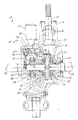
次に図面を参照すると、同様の参照番号は、さまざまな図において、同一の構成要素を示すために使用されており、図1は、本発明の一実施形態による差動装置10の断面図を示す。差動装置10は、共通の回転軸の周囲に配設された車両の2つの車輪(図示せず)が、異なる速度で回転できるようにするために設けられている。差動装置10は、当業者には周知のいくつかの従来技術の構成部品を備えることができる。具体的には、差動装置10は、複数の部材で構成されたハウジング12、およびハウジング12内の開口を介して延び、ピニオン・ギア16を支持するピニオン・シャフト14を備えている。ピニオン・シャフト14を、ハウジング12内で回転させるために、軸受18、20で支持し、入力軸(図示せず)によって駆動することができる。差動装置10は、さらに、デフ・ケース24に結合した、またはそれと一体型であり、ピニオン・ギア16によって駆動されるリング・ギア22を備えることができる。ケース24は、ハウジング12内で軸受26、28によって支持され、スパイダ30を収容することができる。スパイダ30には1つまたは複数の差動歯車32、34が取り付けられている。歯車32、34は、スプラインを付けたサイド・ギア36、38とかみ合って、軸シャフト40、42を駆動する。軸シャフト40、42は、それぞれケース24内に画定された中心孔44、46内に配設されている。軸40、42は、孔44、46内で軸線48の周りで回転可能である。本発明による、差動装置10は、差動ロック機構50も備えることができる。
Referring now to the drawings, wherein like reference numerals are used to refer to the same components in the various figures, FIG. 1 illustrates a cross-sectional view of a differential 10 in accordance with one embodiment of the present invention. Show. The differential 10 is provided to enable two wheels (not shown) of the vehicle arranged around a common axis of rotation to rotate at different speeds. The differential 10 may include several prior art components known to those skilled in the art. Specifically, the differential 10 includes a
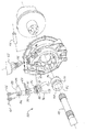
図1および2を参照すると、機構50は、差動装置10を選択的にロックまたはロック解除して、軸40と42間の相対的回転を阻止するために設けられている。機構50は、クラッチ・カラー52、ヨーク54、旋回軸56、レバー58、アクチュエータ・スプリング60、アクチュエータ62、および1つまたは複数の戻しばね64、66を備えることができる。
Referring to FIGS. 1 and 2, a
クラッチ・カラー52は、差動装置10をロックするために使用されるクラッチの一部材を備え、それによって軸40とケース24の間の相対的回転を阻止する。カラー52は、軸40を受けるように構成された孔68を画定する。カラー52は軸40上に取り付けられ、たとえば軸24の外面上に半径方向に、かつカラー52の内面上に半径方向に配置されたスプラインを介して、軸40上で軸方向に可動である。カラー52は、カラー52の軸の一端上に1組の歯70を備えることができ、この歯70は、ケース24の軸の一端上にあるもう1組の歯72と選択的に係合するように構成されている。カラー52上の歯70は、−1度の抜け勾配を付けて機械加工し、回転中に歯70と72間の係合を維持する助けをすることができるようにする。カラー52は、カラー52の他方の軸の端部に近接した、周囲の円周方向に延びる溝74も画定している。
Clutch
ヨーク54を設けて、カラー52を軸方向に駆動体側および反駆動体側に移動させ、それによってカラー52上の歯70をケース24上の歯72と係合および非係合状態に移動させる。図2を参照すると、ヨーク54は、カラー52の溝74内で受けられるように構成された実質的にU形の部材76を備えている。ヨーク54はさらに、溶接または他の従来の締結装置を介して部材76に結合された実質的にU形のブラケット78を備えている。ブラケット78は、部材76と比較して反対方向に開いており、ヨーク54を旋回軸56上で支持できる、各端部に近接した位置合せ開口80、82を備えている。
A
旋回軸56は、ヨーク54およびレバー58の旋回運動を可能にする。軸56は、図2で示したように、ハウジング12内の1つまたは複数の孔84、86内で長手方向の両端部で支持されている。複数のブッシング(図示せず)を孔84、86を画定するハウジング12の内面と軸56の間に置くことができる。軸56は、ヨーク54のブラケット78内の開口80、82を介して延びる。
レバー58は、ヨーク54を旋回軸56の周りで回転させるのに使用するために設けられている。レバー58は、開口86を備えており、開口86を介して軸56が延びてレバー58を支持する。レバー58は、軸56の周りを自由に回転し、ブラケット78の対向する端部の間に配設されている。レバー58はさらに、ばね60の一部を受けるように構成された溝88を画定している。
ばね60は、ヨーク54およびレバー58を結合し、ヨーク54とレバー58の間に配設される。ばね60は、二重コイルばねを含むことができ、その場合、コイルは、旋回軸56を受けるサイズである。ばね60は、ヨーク54に結合すべき2つのタング90、92を備えており、ばね60は、ブラケット78の対向する端部内に受けられる。
A
アクチュエータ62を設けて、レバー58およびヨーク54を、一回転方向(図で示した実施形態では時計回り)で、2つの位置の1つに選択的に移動させる。図で示した実施形態では、ヨーク54は、歯70、72を互いから非係合にする位置に移動している。しかし、アクチュエータ62は、代わりにヨーク54を反対の回転方向に、歯70、72を係合させるもう一方の位置に移動させることができることを理解されたい。本発明の好ましい実施形態では、アクチュエータ62は、電子式アクチュエータ、および具体的にはプッシュ型ソレノイドを含む。しかし、アクチュエータ62は、たとえば磁気ラッチ型ソレノイドを含むさまざまな形態をとることができることを理解されたい。アクチュエータ62は、プランジャ94を備えており、プランジャ94は、アクチュエータ62から選択的に外側に移動して、レバー58と係合し、ヨーク54を回転させる。
An
戻しばね64、66が設けられて、ヨーク54を、アクチュエータ62によって移動した回転方向に反対のもう一方の回転方向(図で示した実施形態では反時計回り)でもう一方の位置に移動させる。図で示した実施形態では、この位置は、歯70、72を係合させる位置である。しかし、やはり戻しばね64、66は、代わりにヨーク54を、反対の方向で歯70、72が非係合になる位置に移動させることができることも理解されたい。戻しばね64、66は、旋回軸56を受けるサイズのコイルを備え、旋回軸56上でヨーク54のブラケット78の両側に配設される。ばね64、66は、一端でヨーク54に、他方の端部でハウジング12に結合される。2つの戻しばね64、66が、図の実施形態に示してあるが、本発明の精神から逸脱することなく、さまざまな数のばねを使用できることを理解されたい。
Return springs 64, 66 are provided to move the
やはり図1および2を参照すると、図で示した実施形態では、戻しばね64、66は、通常、ヨーク54を第1の回転方向に移動させて、カラー52をケース24に向けて駆動軸側の方向に軸に沿って移動させ、歯70、72を係合させる。一構成の実施形態では、ばね64、66は約1.5lbs.の力を与える。歯70、72の非係合は、車両の操縦者またはプログラム可能なマイクロコントローラ(図示せず)によって生成される制御信号(図示せず)を使用して、アクチュエータ62を付勢することによって行われる。一構成の実施形態では、アクチュエータ62のプランジャ94を、最初に12VDCで駆動する。この電流は、プランジャ94を約0.220インチ移動させ、プランジャ94は、スタート時に最初の力約10lbs.を出し、完全に拡張した後は13.5lbs.の力を出す。拡張後、3VDCを使用してプランジャ94を定位置に維持し、プランジャ94によって保持力約9lbs.が出される。プランジャ94の拡張により、レバー58の軸56の周囲の回転が生じる。歯70、72は、軸シャフト40のトルク下では係合したままであるため、レバー58の回転により、ばね60が圧縮されて、一構成の実施形態では、ヨーク54に対して作用する、約7.5lbs.のねじり力またはばね力が生じる。軸シャフト40のトルクが低減すると、ばね60はヨーク54を、時計回りの方向で歯70、72が非係合になる位置に回転させる。本発明の一利点は、プランジャ94に呼応するレバー58の最初の回転によるばね60の圧縮が、第2の力を生じて、ヨーク54をレバー58から離して移動させ、それによって、アクチュエータ62から必要とする力を低減できることである。ヨーク54が旋回すると、ばね60の張力が低減し、対抗する力が平衡になるまで、戻しばね64、66の張力が増大する。本発明における、ばね60、および64、66の使用は、ばね60、および64、66が、ヨーク54を両回転方向に移動させ、その結果クラッチ・カラー52を軸の両方向に移動させることができるために有利である。たとえば、これらのばね力の選択により、クラッチ・カラー52が非係合の場合に、ケース24から軸方向に反駆動軸側に移動する程度が決定される。
Referring again to FIGS. 1 and 2, in the illustrated embodiment, return springs 64, 66 typically move the
アクチュエータ62の消勢、またはアクチュエータ62に対する電源の故障の場合、戻しばね64、66は、ヨークを、クラッチ・カラー52の歯70およびケース24の歯72が係合する位置に移動させる。ヨーク54の移動は、ばね60を介してレバー58も対応して移動させ、それによって、プランジャ94をアクチュエータ62内に引込めた位置に移動させる。図1で示した実施形態では、戻しばね64、66は、ヨーク54を反時計回りの方向に移動させ、それによってカラー52を駆動軸側に向けて軸方向に移動させる。
In the event of
本発明による差動装置は、従来技術の差動装置に対する改良を提示するものである。本発明の差動装置は、クラッチ・カラー52およびデフ・ケース24上の歯70と72間の係合のレベルに関係なく、車両の走行中に自由に動作することができる。本発明の差動装置は、電子的に制御されたアクチュエータ62の使用によって、差動ロック機構を手動で操作する必要を省くこともできる。本発明の差動装置のロック機構は、レバー58がディファレンシャル・ハウジング12の内部に配設された、小型のものであるため、車両のスペースを節約することもできる。
The differential according to the present invention represents an improvement over the prior art differential. The differential of the present invention is free to operate while the vehicle is traveling, regardless of the level of engagement between the
本発明を、本発明の好ましい実施形態を参照して、具体的に図で示し説明したが、頭記の特許請求の範囲で定義したように、本発明の精神および範囲から逸脱することなく、本発明にさまざまな変更および修正を加えることができることは、当業者には周知である。 While the invention has been particularly shown and described with reference to preferred embodiments thereof, as defined in the appended claims, without departing from the spirit and scope of the invention, It is well known to those skilled in the art that various changes and modifications can be made to the present invention.
10 差動装置
12 ハウジング
14 ピニオン・シャフト
16 ピニオン・ギア
18、20 軸受
22 リング・ギア
24 デフ・ケース
26、28 軸受
30 スパイダ
32、34 差動歯車
36、38 サイド・ギア
40、42 軸シャフト
44、46 中心孔
48 軸線
50 差動ロック機構
52 クラッチ・カラー
54 ヨーク
56 旋回軸
58 レバー
60 アクチュエータ・スプリング
62 アクチュエータ
64、66 戻しばね
68 孔
70、72 歯
74 溝
76 部材
78 ブラケット
80、82 開口
84、86 孔
88 溝
90、92 タング
94 プランジャ
Reference Signs List 10
Claims (22)
前記中心孔内に配設され、前記孔内で回転可能な駆動軸と、
前記駆動軸上に取り付けられ、前記第1組の歯と選択的に係合し、前記駆動軸と前記デフ・ケースの間の相対的回転を阻止するように構成された第2組の歯を有し、さらに溝を画定している、クラッチ・カラーと、
旋回軸上で支持され、前記クラッチ・カラー内の前記溝内に受けられるヨークと、
前記旋回軸上で支持されるレバーと、
前記ヨークと前記レバーの間に配設される第1のばねと、
前記レバーおよび前記ヨークを第1の回転方向で第1の位置に選択的に移動させるアクチュエータと、
前記レバーおよび前記ヨークを第2の回転方向で第2の位置に移動させる第2のばねとを備え、
前記第1組および前記第2組の歯が、前記第1および前記第2の位置の1つで係合し、前記第1組および前記第2組の歯が、前記第1および前記第2の位置の他方の位置で非係合になるようにする、差動装置。 A differential case having a first set of teeth and defining a central hole;
A drive shaft disposed in the center hole and rotatable in the hole;
A second set of teeth mounted on the drive shaft and selectively engaged with the first set of teeth to prevent relative rotation between the drive shaft and the differential case; A clutch collar that has and further defines a groove,
A yoke supported on a pivot axis and received in the groove in the clutch collar;
A lever supported on the pivot axis;
A first spring disposed between the yoke and the lever;
An actuator for selectively moving the lever and the yoke to a first position in a first rotational direction;
A second spring for moving the lever and the yoke to a second position in a second rotational direction,
The first set and the second set of teeth engage at one of the first and second positions, and the first set and the second set of teeth engage the first and second sets of teeth. A differential device that is disengaged at the other of the positions.
前記中心孔内に配設され、前記孔内で回転可能な駆動軸と、
前記駆動軸上に取り付けられ、前記第1組の歯と選択的に係合し、前記駆動軸と前記デフ・ケースの間の相対的回転を阻止するように構成された第2組の歯を有し、さらに溝を画定している、クラッチ・カラーと、
旋回軸上で支持され、前記クラッチ・カラー内の前記溝内に受けられるヨークと、
前記旋回軸上で支持されるレバーと、
前記ヨークと前記レバーの間に配設される第1のばねと、
前記レバーおよび前記ヨークを第1の回転方向で第1の位置に選択的に移動させ、前記第1の位置は、前記第1組の歯が前記第2組の歯から非係合である場合に得られる、アクチュエータと、
前記レバーおよび前記ヨークを第2の回転方向で第2の位置に移動させ、前記第2の位置は、前記第1組の歯が前記第2組の歯から非係合の場合に得られる、第2のばねとを備える、差動装置。 A differential case having a first set of teeth and defining a central hole;
A drive shaft disposed in the center hole and rotatable in the hole;
A second set of teeth mounted on the drive shaft and selectively engaged with the first set of teeth to prevent relative rotation between the drive shaft and the differential case; A clutch collar that has and further defines a groove,
A yoke supported on a pivot axis and received in the groove in the clutch collar;
A lever supported on the pivot axis;
A first spring disposed between the yoke and the lever;
Selectively moving the lever and the yoke to a first position in a first rotational direction, wherein the first position is when the first set of teeth is disengaged from the second set of teeth. And the actuator obtained in
Moving the lever and the yoke to a second position in a second direction of rotation, wherein the second position is obtained when the first set of teeth is disengaged from the second set of teeth; A differential comprising: a second spring;
前記中心孔内に配設され、前記孔内で回転可能な駆動軸と、
前記駆動軸上に取り付けられ、前記第1組の歯と選択的に係合し、前記駆動軸と前記デフ・ケースの間の相対的回転を阻止するように構成された第2組の歯を有し、さらに溝を画定している、クラッチ・カラーと、
旋回軸上で支持され、前記クラッチ・カラー内の前記溝内に受けられるヨークと、
前記旋回軸上で支持されるレバーと、
前記ヨークと前記レバーの間に配設される二重コイルばねと、
付勢されると、前記レバーおよび前記ヨークを第1の回転方向で第1の位置に選択的に移動させ、前記第1の位置は、前記第1組の歯が前記第2組の歯から非係合の場合に得られる、ソレノイドと、
前記レバーおよび前記ヨークを第2の回転方向で第2の位置に移動させ、前記第2の位置は、前記第1組の歯が前記第2組の歯から非係合の場合に得られる、少なくとも1つの戻しばねとを備える、差動装置。 A differential case having a first set of teeth and defining a central hole;
A drive shaft disposed in the center hole and rotatable in the hole;
A second set of teeth mounted on the drive shaft and selectively engaged with the first set of teeth to prevent relative rotation between the drive shaft and the differential case; A clutch collar that has and further defines a groove,
A yoke supported on a pivot axis and received in the groove in the clutch collar;
A lever supported on the pivot axis;
A double coil spring disposed between the yoke and the lever,
When energized, the lever and the yoke are selectively moved to a first position in a first rotational direction, wherein the first position is such that the first set of teeth is displaced from the second set of teeth. A solenoid obtained in the case of disengagement,
Moving the lever and the yoke to a second position in a second direction of rotation, wherein the second position is obtained when the first set of teeth is disengaged from the second set of teeth; A differential comprising at least one return spring.
21. The differential of claim 20, wherein the single acting solenoid comprises a magnetic latching solenoid.
Applications Claiming Priority (1)
| Application Number | Priority Date | Filing Date | Title |
|---|---|---|---|
| US10/316,411 US6835155B2 (en) | 2002-12-11 | 2002-12-11 | Position compensating differential locking mechanism |
Publications (2)
| Publication Number | Publication Date |
|---|---|
| JP2004190859A true JP2004190859A (en) | 2004-07-08 |
| JP2004190859A5 JP2004190859A5 (en) | 2007-02-01 |
Family
ID=32505945
Family Applications (1)
| Application Number | Title | Priority Date | Filing Date |
|---|---|---|---|
| JP2003412833A Pending JP2004190859A (en) | 2002-12-11 | 2003-12-11 | Position compensation differential lock mechanism |
Country Status (2)
| Country | Link |
|---|---|
| US (2) | US6835155B2 (en) |
| JP (1) | JP2004190859A (en) |
Cited By (1)
| Publication number | Priority date | Publication date | Assignee | Title |
|---|---|---|---|---|
| JP2011121458A (en) * | 2009-12-10 | 2011-06-23 | Kawasaki Heavy Ind Ltd | Differential and rough terrain vehicle |
Families Citing this family (17)
| Publication number | Priority date | Publication date | Assignee | Title |
|---|---|---|---|---|
| CA2451893C (en) * | 2002-12-02 | 2013-04-09 | Tesma International Inc. | Differential housing with integrated ring gear |
| US6835155B2 (en) * | 2002-12-11 | 2004-12-28 | Dana Corporation | Position compensating differential locking mechanism |
| US7326145B2 (en) * | 2003-07-04 | 2008-02-05 | Samuel Abraham | Differential for motor vehicles with device for locking thereof |
| JP2006071071A (en) * | 2004-09-06 | 2006-03-16 | Gkn ドライブライン トルクテクノロジー株式会社 | Differential device |
| US7896120B2 (en) * | 2008-04-02 | 2011-03-01 | Yamaha Hatsudoki Kabushiki Kaisha | Small-sized vehicle with improved drivetrain |
| GB2475888A (en) * | 2009-12-04 | 2011-06-08 | Meritor Heavy Vehicle Sys Ltd | Differential lock actuator |
| US8454471B2 (en) * | 2010-07-21 | 2013-06-04 | Ford Global Technologies, Llc | Electronic locking differential |
| RU2462633C1 (en) * | 2011-03-25 | 2012-09-27 | Открытое акционерное общество "КАМАЗ" | Mechanism of differential lock (versions) |
| US8944952B2 (en) * | 2013-06-21 | 2015-02-03 | Arvinmeritor Technology, Llc | Differential assembly having a clutch collar actuator mechanism |
| US9382992B2 (en) * | 2014-09-26 | 2016-07-05 | Ford Global Technologies, Llc | Control of locking differential |
| CN104534086B (en) * | 2014-12-23 | 2017-04-12 | 东风汽车公司 | Electronically-control type differential lock control mechanism and method |
| CN106151448B (en) * | 2015-03-30 | 2018-11-09 | 长城汽车股份有限公司 | A kind of limited-slip differential, speed changer and automobile |
| CN107687510A (en) * | 2016-08-04 | 2018-02-13 | 株式会社捷太格特 | Contact maker and differentiator |
| CN106678327B (en) * | 2016-12-26 | 2019-08-06 | 湖北航天技术研究院特种车辆技术中心 | Differential assembly |
| US11346432B2 (en) * | 2018-03-07 | 2022-05-31 | Eaton Intelligent Power Limited | Electrically controlled automatic locker differential |
| CN110733536B (en) * | 2019-09-25 | 2021-09-10 | 交控科技股份有限公司 | Train screening method and system based on mobile block |
| CN115325129B (en) * | 2022-07-01 | 2024-04-05 | 浙江吉利控股集团有限公司 | Differential structure and vehicle |
Family Cites Families (10)
| Publication number | Priority date | Publication date | Assignee | Title |
|---|---|---|---|---|
| US968224A (en) | 1909-09-08 | 1910-08-23 | Austin M Wolf | Differential-gear lock. |
| US1338720A (en) * | 1919-12-09 | 1920-05-04 | Harry O Darr | Differential-locking mechanism |
| US1511908A (en) | 1924-02-27 | 1924-10-14 | Pickering Jack Ivan | Differential lock |
| GB966928A (en) | 1962-02-27 | 1964-08-19 | Tractor Res Ltd | Improvements in or relating to control mechanism for tractors |
| US3202016A (en) * | 1962-04-11 | 1965-08-24 | Case Co J I | Tractor improvements |
| US4263824A (en) | 1976-09-22 | 1981-04-28 | Eaton Corporation | Differential device |
| US4715248A (en) * | 1986-07-11 | 1987-12-29 | Gant Lawrence A | Manual differential lock-up |
| DE58904987D1 (en) | 1988-10-05 | 1993-08-26 | Zahnradfabrik Friedrichshafen | LOCKABLE DIFFERENTIAL GEARBOX. |
| US5171192A (en) | 1990-12-31 | 1992-12-15 | Dana Corporation | Locking differential |
| US6835155B2 (en) * | 2002-12-11 | 2004-12-28 | Dana Corporation | Position compensating differential locking mechanism |
-
2002
- 2002-12-11 US US10/316,411 patent/US6835155B2/en not_active Expired - Fee Related
-
2003
- 2003-12-11 JP JP2003412833A patent/JP2004190859A/en active Pending
-
2004
- 2004-11-16 US US10/989,868 patent/US7048668B2/en not_active Expired - Fee Related
Cited By (1)
| Publication number | Priority date | Publication date | Assignee | Title |
|---|---|---|---|---|
| JP2011121458A (en) * | 2009-12-10 | 2011-06-23 | Kawasaki Heavy Ind Ltd | Differential and rough terrain vehicle |
Also Published As
| Publication number | Publication date |
|---|---|
| US7048668B2 (en) | 2006-05-23 |
| US20050090357A1 (en) | 2005-04-28 |
| US6835155B2 (en) | 2004-12-28 |
| US20040116236A1 (en) | 2004-06-17 |
Similar Documents
| Publication | Publication Date | Title |
|---|---|---|
| JP2004190859A (en) | Position compensation differential lock mechanism | |
| JP3028243B2 (en) | Limited slip differential gear mechanism | |
| RU2408810C2 (en) | Lock mechanism of mechanically locking differential | |
| CN105229344B (en) | shift-by-wire transmission | |
| JP2003184993A (en) | Gear module for clutch actuator in differential assembly | |
| EP1481873A1 (en) | Steer-by-wire system | |
| JP2000240760A (en) | Differential gear mechanism | |
| KR930016267A (en) | Automotive Multifunction Energy Saving System | |
| CN102102752A (en) | Block mounted lock-out mechanism | |
| JPH0130652B2 (en) | ||
| CN111433490A (en) | Differential device capable of two-stage limiting differential motion | |
| US5960670A (en) | Actuator for gear transfer case with cushion at end of travel | |
| US10988022B2 (en) | Electro-mechanical on demand (EMOD) transfer case—dual drive gear and shift fork consolidation | |
| WO2013039074A1 (en) | Transmission | |
| JP6740712B2 (en) | Driving force connecting/disconnecting device | |
| JP4127286B2 (en) | Parking lock device for transmission | |
| JP2003222165A (en) | Torque coupling mechanism and clutch mechanism | |
| JPS6330537B2 (en) | ||
| US7707903B2 (en) | Actuator employing a standby mechanism | |
| JPH0464747A (en) | Differential limiting device | |
| JP4539306B2 (en) | Torque limit mechanism and variable transmission ratio mechanism with torque limit mechanism | |
| US6332523B1 (en) | Axle assembly parking brake mechanism | |
| JP2006189149A (en) | Differential device | |
| CN115362321B (en) | Transmission for at least partially electrically driven vehicle and synchronization device for such a transmission | |
| JP2007015603A (en) | Torque limit mechanism and variable transmission ratio mechanism with torque limit mechanism |
Legal Events
| Date | Code | Title | Description |
|---|---|---|---|
| RD01 | Notification of change of attorney |
Free format text: JAPANESE INTERMEDIATE CODE: A7426 Effective date: 20060119 |
|
| A521 | Request for written amendment filed |
Free format text: JAPANESE INTERMEDIATE CODE: A523 Effective date: 20061208 |
|
| A621 | Written request for application examination |
Free format text: JAPANESE INTERMEDIATE CODE: A621 Effective date: 20061208 |
|
| A711 | Notification of change in applicant |
Free format text: JAPANESE INTERMEDIATE CODE: A711 Effective date: 20090304 |
|
| A521 | Request for written amendment filed |
Free format text: JAPANESE INTERMEDIATE CODE: A821 Effective date: 20090304 |
|
| A977 | Report on retrieval |
Free format text: JAPANESE INTERMEDIATE CODE: A971007 Effective date: 20090515 |
|
| A131 | Notification of reasons for refusal |
Free format text: JAPANESE INTERMEDIATE CODE: A131 Effective date: 20090526 |
|
| A601 | Written request for extension of time |
Free format text: JAPANESE INTERMEDIATE CODE: A601 Effective date: 20090824 |
|
| A602 | Written permission of extension of time |
Free format text: JAPANESE INTERMEDIATE CODE: A602 Effective date: 20090827 |
|
| A02 | Decision of refusal |
Free format text: JAPANESE INTERMEDIATE CODE: A02 Effective date: 20100209 |