EP1481627B1 - A body cavity-observing apparatus - Google Patents
A body cavity-observing apparatus Download PDFInfo
- Publication number
- EP1481627B1 EP1481627B1 EP04019657A EP04019657A EP1481627B1 EP 1481627 B1 EP1481627 B1 EP 1481627B1 EP 04019657 A EP04019657 A EP 04019657A EP 04019657 A EP04019657 A EP 04019657A EP 1481627 B1 EP1481627 B1 EP 1481627B1
- Authority
- EP
- European Patent Office
- Prior art keywords
- prism
- endoscope
- body cavity
- endoscope image
- observing apparatus
- Prior art date
- Legal status (The legal status is an assumption and is not a legal conclusion. Google has not performed a legal analysis and makes no representation as to the accuracy of the status listed.)
- Expired - Lifetime
Links
- 230000003287 optical effect Effects 0.000 claims description 39
- 239000007788 liquid Substances 0.000 claims description 16
- 230000004075 alteration Effects 0.000 claims description 13
- 238000003384 imaging method Methods 0.000 claims description 10
- 230000007246 mechanism Effects 0.000 claims description 10
- 210000001835 viscera Anatomy 0.000 description 8
- 238000005452 bending Methods 0.000 description 6
- 230000003245 working effect Effects 0.000 description 6
- 230000015556 catabolic process Effects 0.000 description 4
- 238000006731 degradation reaction Methods 0.000 description 4
- XEEYBQQBJWHFJM-UHFFFAOYSA-N Iron Chemical compound [Fe] XEEYBQQBJWHFJM-UHFFFAOYSA-N 0.000 description 2
- 229910052742 iron Inorganic materials 0.000 description 1
- 238000000034 method Methods 0.000 description 1
Images


Classifications
-
- A—HUMAN NECESSITIES
- A61—MEDICAL OR VETERINARY SCIENCE; HYGIENE
- A61B—DIAGNOSIS; SURGERY; IDENTIFICATION
- A61B1/00—Instruments for performing medical examinations of the interior of cavities or tubes of the body by visual or photographical inspection, e.g. endoscopes; Illuminating arrangements therefor
- A61B1/00163—Optical arrangements
- A61B1/00174—Optical arrangements characterised by the viewing angles
- A61B1/00183—Optical arrangements characterised by the viewing angles for variable viewing angles
-
- A—HUMAN NECESSITIES
- A61—MEDICAL OR VETERINARY SCIENCE; HYGIENE
- A61B—DIAGNOSIS; SURGERY; IDENTIFICATION
- A61B1/00—Instruments for performing medical examinations of the interior of cavities or tubes of the body by visual or photographical inspection, e.g. endoscopes; Illuminating arrangements therefor
- A61B1/002—Instruments for performing medical examinations of the interior of cavities or tubes of the body by visual or photographical inspection, e.g. endoscopes; Illuminating arrangements therefor having rod-lens arrangements
-
- A—HUMAN NECESSITIES
- A61—MEDICAL OR VETERINARY SCIENCE; HYGIENE
- A61B—DIAGNOSIS; SURGERY; IDENTIFICATION
- A61B1/00—Instruments for performing medical examinations of the interior of cavities or tubes of the body by visual or photographical inspection, e.g. endoscopes; Illuminating arrangements therefor
- A61B1/04—Instruments for performing medical examinations of the interior of cavities or tubes of the body by visual or photographical inspection, e.g. endoscopes; Illuminating arrangements therefor combined with photographic or television appliances
- A61B1/042—Instruments for performing medical examinations of the interior of cavities or tubes of the body by visual or photographical inspection, e.g. endoscopes; Illuminating arrangements therefor combined with photographic or television appliances characterised by a proximal camera, e.g. a CCD camera
-
- G—PHYSICS
- G02—OPTICS
- G02B—OPTICAL ELEMENTS, SYSTEMS OR APPARATUS
- G02B23/00—Telescopes, e.g. binoculars; Periscopes; Instruments for viewing the inside of hollow bodies; Viewfinders; Optical aiming or sighting devices
- G02B23/24—Instruments or systems for viewing the inside of hollow bodies, e.g. fibrescopes
- G02B23/2407—Optical details
- G02B23/2423—Optical details of the distal end
-
- G—PHYSICS
- G02—OPTICS
- G02B—OPTICAL ELEMENTS, SYSTEMS OR APPARATUS
- G02B5/00—Optical elements other than lenses
- G02B5/04—Prisms
- G02B5/06—Fluid-filled or evacuated prisms
Definitions
- This invention relates to a body cavity-observing apparatus for observing an internal organ or the like in the body cavity, including an endoscope with an imaging optical system at the forefront thereof to photograph an endoscope image.
- endoscopes to be used in body cavities are classified as rigid endoscopes or fiberscopes.
- rigid endoscopes In order to obtain a different endoscope image through the movement of an endoscope, it is required in a rigid endoscope that the rigid endoscope itself is moved and it is required in a fiberscope that the fiberscope itself is moved or bended.
- endoscope manupulators in which endoscopes are installed have been developed.
- the endoscope manupulator can move the endoscope therein rapidly and obtain a different scope effectively.
- the endoscope manupulator drives the conventional endoscope only actively, it may degrade the working property because of the movement or bending of the endoscope by an operator.
- the forefront of the endoscope may be made an approach to an internal organ more than necessary.
- each image data becomes very small, resulting in the degradation of the resolution and thus, the degradation of the endoscope image in quality.
- the selected optical image also becomes very small, resulting in the degradation of the resolution and thus, the degradation of the endoscope image in quality, as mentioned above.
- the super wide-angle optical lens provides more distorted images at the fringes than at the center, all of the wide-angle optical image can not be provided practically.
- this invention relates to a body cavity-observing apparatus comprising an endoscope with an imaging optical system on the front edge thereof, a prism movably mounted on the forefront of the imaging optical system, and an actuator to drive the prism on a given command signal, whereby a different endoscope image is obtained through the movement of the prism.
- the different endoscope image can be easily obtained by moving the prism without the mechanical movement or the mechanical bending of the endoscope.
- a wide range endoscope image can be easily obtained.
- the resolution of the thus obtained endoscope image can be enhanced.
- the working property and the safety of not making an approach to an internal organ more than necessary are improved.
- the invention is defined by the features of claim 1.
- the prism includes a first and a second wedged prisms having the same vertical angle which are provided closely and of which their adjacent opposite surfaces are orthogonal to the optical axis of the wedge prisms
- the actuator includes a first and a second outer tubes which are attached independently movably to the first and the second wedge prisms and a first and a second motors to rotate the first and the second wedge prisms around the optical axis, respectively.
- the different endoscope image can be easily obtained through the independent rotations of the wedge prisms, and thus, the wide range endoscope image can be easily obtained.
- the prism includes one wedge prism
- the actuator includes an outer tube movably provided on the periphery of the endoscope, a joining shaft to join the wedge prism and the outer tube, a first motor to tilt the wedge prism for the optical axis via the joining shaft and a second motor to rotate the wedge prism around the optical axis through the rotation of the outer tube.
- the different endoscope image can be easily obtained through the rotation and tilt of the one wedge prism, and thus, the wide range endoscope image can be obtained.
- the prism includes a liquid prism
- the actuator includes a first and a second link mechanisms which adjust the tilt angles for two directions orthogonal to the optical axis, respectively.
- the first and the second link mechanisms comprises pairs of link shafts composed of planer portions joined with the periphery of the liquid prism and orthogonal portions orthogonally followed by the planer portions, link members to support the orthogonal portions of the link shafts, and motors to rotate the link members.
- the different endoscope image can be easily obtained through the backward and forward movement of the liquid prism, and thus, the wide range endoscope image can be easily obtained.
- the link members have their elongated holes, respectively, and the link shafts are moved backward and forward by slipping the orthogonal portions in the elongated holes through the rotation of the link members by the motors.
- a position-detecting means to detect the position of the prism is provided.
- An endoscope image is calibrated in its color aberration or distortion on the basis of the prism position information from the position-detecting means. Therefore, the resolution of the endoscope image can be more enhanced.
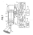
- Fig. 1 is a schematic view showing the entire structure of a body cavity-observing apparatus.
- the depicted body cavity-observing apparatus has, as an endoscope, a rigid endoscope 1 having about 10 mm diameter in its part to be inserted and about 300 mm entire length.
- the endoscope may be constructed of a fiberscope.
- a CCD camera 2 is provided, as an imaging means, in the right side of Fig. 1.
- an imaging optical system (not shown) to photograph an endoscope image is mounted at the forefront of the rigid endoscope 1 (in the left side of Fig. 1).
- a first and a second wedge prisms 3 and 4 to constitute a prism means are attached to the forefront of the imaging optical system movably.
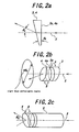
- the wedge prisms 3 and 4 have the same wedge vertical angle ⁇ w as shown in Fig. 2(a), and are positioned closely so that their first surfaces 3a and 4a perpendicular to the optical axis X are opposed each other as shown in Fig. 2(b).
- the wedge prisms 3, 4 and the rigid endoscope 1 are covered doubly with a first and a second outer tubes 5 and 6 which are independently movable. At the right edges of the outer tubes 5 and 6 are attached gears (not shown), to which gears 7b and 8b to be joined with the forefronts of the rotation shafts 7a and 8a of a first and a second motors 7 and 8 are checked. Rotary encoders 9 and 10 to detect the motor driving amount (rotation number) are joined with the right edges of the motors 7 and 8.
- the outer tubes 5, 6 and the motors 7 and 8 constitute an actuator to drive the wedge prisms 3 and 4.
- a controller 11 to control the driving amounts of the motors 7 and 8 is provided. To the controller 11 are input a command signal from an operating interface 12 controlled by an operator, the driving amounts of the motors 7 and 8 detected by the rotary encoders 9 and 10, and an endoscope image from the CCD camera 2.
- the controller 11 has a scope controlling part 13 to control the driving amounts of the motors 7 and 8 based on the command signal from the operating interface 12, and a prism position-detecting part 14 to detect the movement positions of the wedge prisms 3 and 4 based on the driving amounts of the motors 7 and 8 detected by the rotary encoders 9 and 10.
- the controller 11 has a calibration table 16 for color aberration and distortion, and an image processing part 15 to calibrate the color aberration and distortion of an endoscope image detected by the CCD camera 2 based on the calibration table 16.
- a monitor 17 may be prepared so that the endoscope image can be observed.
- the controller 11, the operating interface 12 and the monitor 17 may be constructed of a general-purpose computer, for example.
- the scope controlling part 13, the prism position-detecting part 14 and the image processing part 15 of the controller 11 may be constructed of a given software installed in the computer, and the calibration table 16 of the controller 11 may be constructed of the data recorded in a memory (RAM, ROM, hard disk, etc.) in the computer.
- the operating interface 12 may be constructed of the key board or the mouse of the computer.
- the scope controlling part 13, the prism position-detecting part 14 and the image processing part 15 may be constructed of other devices, and the image processing part 15 may be made of a hardware such as an image processing board.
- ⁇ d arcsin nsin ⁇ w - ⁇ w
- reference character "n" designates the refractive index of the wedge prism 4.
- the endoscope image in the ⁇ d direction can be observed by the wedge prism 4 movably attached at the forefront of the rigid endoscope 1. If the wedge prism 4 is rotated around the optical axis X of the rigid endoscope 1, the endoscope image within the region of the ⁇ d direction around the optical axis X can be observed.
- the light beam can be deflected in a given direction within a conical shape defined by the wedge prisms 3 and 4.
- the maximum deflection angle is a half of the vertical angle of the conical shape, and is almost defined as 2 ⁇ d if the vertical angles of the wedge prisms 3 and 4 are very small. Therefore, the light beam can be deflected within a region of 4 ⁇ d by the wedge prisms 3 and 4, as shown in Fig. 2(b).
- the deflecting condition of the light beam from the optical axis X is controlled on the basis of the command signal from the operating interface 12, and a different endoscope image can be obtained within the 4 ⁇ d region.
- the observed endoscope image may be distorted to some degree due to the incident angle of the light beam, the angle of the incident surface of the wedge prisms and the distance of the light beam from the optical axis X.
- the observed endoscope image has color aberration therein.
- the degrees of the distortion and the color aberration of the endoscope image can be obtained from the calculation or the calibration, depending on the positions of the wedge prisms when they are rotated around the optical axis X, and thus, in this example, stored in the calibration table 16 of the controller 11.
- the rotary encoders 9 and 10 as position-detecting means detect the driving amounts of the motors 7 and 8, and the positions of the wedge prisms 3 and 4 to define the endoscope image are measured on the driving amounts. Then, the calibrations for the color aberration and the distortion of the endoscope image related to the positions of the wedge prisms are determined from the calibration table 16. Subsequently, the endoscope image is calibrated in its color aberration and the distortion by the image processing part 15 on the measured color aberration calibration and distortion calibration, and is displayed on the monitor 17. If the color aberration or the distortion is very small and negligible, the calibration for the one may be omitted.
- the resolution of the endoscope image can be enhanced.
- the quality of the endoscope image can be improved.
- the endoscope image is calibrated in its color aberration and distortion on the calibration table 16, the quality of the endoscope image can be more enhanced.
- Fig. 3 is a schematic view showing the entire structure of another body cavity-observing apparatus according to another example.
- the body cavity-observing apparatus has only one wedge prism. Therefore, the actuator is modified so as to adapt to the one wedge prism.
- the other parts are similar to the ones in Fig. 1, so that the same reference characters are given to the ones.
- the only one wedge prism 4 is attached to the forefront of the not shown imaging optical system provided at the left edge of the rigid endoscope 1 so that the right-handed surface is perpendicular to the optical axis.
- the above-mentioned actuator is constructed of an outer tube 21 movably provided on the periphery of the rigid endoscope 1, a joining shaft 23 to join the wedge prism 4 and the outer tube 21 via a rotation shaft 22, a pulley 24 joined with the forefront of the rotation shaft 22, a belt 25 associated with the pulley 24, a pulley 26 provided on the outer tube 21, a first motor 28 having a rotation shaft 27 joined with the pulley 26, and a second motor 31 having a gear 29 joined via a rotation shaft 30.
- another rotation shaft 22, another joining shaft 23 and another pulley 24 are provided on the back side of the body cavity-observing apparatus so as to oppose the rotation shaft 22, the joining shaft 23 and the pulley 24 which are provided on the front side thereof. That is, the wedge prism 4 is sandwiched by the pair of rotation shafts 22, the pair of joining shafts 23 and the pair of pulleys 24.
- the wedge prism 4 is rotated by a given angle in the direction designated by the arrow D around the rotation shaft 22 by the motor 28 via the rotation shaft 27, the pulley 26, the belt 25 and the pulley 24. As a result, the prism 4 is moved at its different position from its starting position.
- the only one wedge prism is rotated in the arrow C direction and tilted in the arrow D direction, instead of independently rotating the wedge prisms 3 and 4 as mentioned in Fig. 1. Therefore, in this case, a different endoscope image can be obtained from the movement of the wedge prism 4.
- the working property can be developed and the forefront of the endoscope can not be made an approach to an internal organ more than necessary.
- the resolution of the endoscope image can be enhanced.
- the endoscope image can be also calibrated in its color aberration and distortion on the calibration table 16.
- Fig. 4 is a schematic view showing the entire structure of a body cavity-observing apparatus according to the present invention. Compared with the body cavity-observing apparatus shown in Fig. 3, a liquid prism is employed instead of the wedge prism, and an actuator to move the liquid prism backward and forward along the optical axis X is provided.
- the other parts are similar to the ones in Fig. 3, so that the same reference characters are given to the ones.
- the liquid prism 41 is attached to the forefront of the not shown imaging optical system provided at the left edge of the rigid endoscope 1 so that the right-handed surface is perpendicular to the optical axis X.
- the actuator is constructed of a first and a second link mechanisms 42 and 43 which adjust the tilt angles for the Y axis and the Z axis orthogonal to the X axis.
- the link mechanisms 42 and 43 have pairs of link shafts 44 composed of planer portions 44a joined with the periphery of the liquid prism 41 and orthogonal portions 44b orthogonally followed by the planer portions 44a, link members 45 to support the orthogonal portions 44b of the link shafts 44, and motors 46 to rotate the link members 45 around the Y axis and Z axis, respectively.
- the link members 45 have their elongated holes 45a, respectively, and the link shafts 44 are moved backward and forward by slipping the orthogonal portions 44b in the elongated holes 45a through the rotation of the link members 45 by the motors 46. Then, rotary encoders 47 to count the rotation numbers of the motors 46 are attached on the motors 46, respectively.
- the scope controlling operation using the body cavity-observing apparatus shown in Fig. 4 will be described hereinafter.
- the driving amounts of the motors 46 are determined by the scope controlling part 13, to drive the motors 46 by the determined driving amounts.
- the link mechanisms 42 and 43 are moved backward and forward along the X axis by the motors 46, to move the liquid prism 41 backward and forward in the directions designated by the arrows E and F shown in Fig. 4. Therefore, the forefront surface (left-handed surface) of the liquid prism 41 is tilted by a given angle. As a result, the liquid prism 41 is moved at its different position from its starting position without the mechanical movement or bending of the rigid endoscope.
- the only one liquid prism 41 is moved backward and forward in the arrows E and F directions, instead of rotating in the arrow C direction around the optical axis X and tilting in the arrow D direction the only one wedge prism 4 as mentioned in Fig. 3. Therefore, in this case, a different endoscope image can be obtained from the forward and backward movement of the liquid prism 41.
- the working property can be developed and the forefront of the endoscope can not be made an approach to an internal organ more than necessary.
- the resolution of the endoscope image can be enhanced.
- the endoscope image can be also calibrated in its color aberration and distortion on the calibration table 16.
- the magnification and reduction of the endoscope image can be also carried out by a given optical system for the zoom mechanism, in addition to the above-mentioned optical system such as the rigid endoscope and the prism to obtain a different endoscope image and thus a wide range endoscope image. Therefore, since the body cavity-observing apparatus does not require the mechanical bending or the mechanical movement, the working property or the safety of not making an approach to an internal organ more than necessary can be developed under a surgical operation.
Landscapes
- Health & Medical Sciences (AREA)
- Life Sciences & Earth Sciences (AREA)
- Physics & Mathematics (AREA)
- Surgery (AREA)
- Optics & Photonics (AREA)
- Engineering & Computer Science (AREA)
- Veterinary Medicine (AREA)
- Pathology (AREA)
- Radiology & Medical Imaging (AREA)
- Biophysics (AREA)
- Nuclear Medicine, Radiotherapy & Molecular Imaging (AREA)
- Biomedical Technology (AREA)
- Heart & Thoracic Surgery (AREA)
- Medical Informatics (AREA)
- Molecular Biology (AREA)
- Animal Behavior & Ethology (AREA)
- General Health & Medical Sciences (AREA)
- Public Health (AREA)
- General Physics & Mathematics (AREA)
- Astronomy & Astrophysics (AREA)
- Instruments For Viewing The Inside Of Hollow Bodies (AREA)
- Endoscopes (AREA)
- Optical Elements Other Than Lenses (AREA)
Description
- This invention relates to a body cavity-observing apparatus for observing an internal organ or the like in the body cavity, including an endoscope with an imaging optical system at the forefront thereof to photograph an endoscope image.
- Generally, endoscopes to be used in body cavities are classified as rigid endoscopes or fiberscopes. In order to obtain a different endoscope image through the movement of an endoscope, it is required in a rigid endoscope that the rigid endoscope itself is moved and it is required in a fiberscope that the fiberscope itself is moved or bended.
- Recently, various endoscope manupulators in which endoscopes are installed have been developed. The endoscope manupulator can move the endoscope therein rapidly and obtain a different scope effectively. However, since the endoscope manupulator drives the conventional endoscope only actively, it may degrade the working property because of the movement or bending of the endoscope by an operator. Moreover, if the endoscope manupulator is operated mistakenly from a mistaken data input, the forefront of the endoscope may be made an approach to an internal organ more than necessary.
- In order to iron out the above conventional matters, the publications of unexamined patent applications Tokukai Hei
8-164148 JP A 8-164148 JP A 10-290777 - In the former case, since the recorded endoscope image data are based on the wide-angle optical image, each image data becomes very small, resulting in the degradation of the resolution and thus, the degradation of the endoscope image in quality. In the latter case, if the part of the super wide-angle optical image is selected, the selected optical image also becomes very small, resulting in the degradation of the resolution and thus, the degradation of the endoscope image in quality, as mentioned above. Moreover, since the super wide-angle optical lens provides more distorted images at the fringes than at the center, all of the wide-angle optical image can not be provided practically.
- It is an object of the present invention to provide a body cavity-observing apparatus which can provide various endoscope images in good quality without the movement or bending of an endoscope.
- Therefore, this invention relates to a body cavity-observing apparatus comprising an endoscope with an imaging optical system on the front edge thereof, a prism movably mounted on the forefront of the imaging optical system, and an actuator to drive the prism on a given command signal, whereby a different endoscope image is obtained through the movement of the prism.
- According to the body cavity-observing apparatus of the present invention, the different endoscope image can be easily obtained by moving the prism without the mechanical movement or the mechanical bending of the endoscope. As a result, a wide range endoscope image can be easily obtained. Moreover, since only a given area directed by the prism is observed, the resolution of the thus obtained endoscope image can be enhanced. Furthermore, for example under a surgical operation, the working property and the safety of not making an approach to an internal organ more than necessary are improved. The invention is defined by the features of claim 1.
- In an example, the prism includes a first and a second wedged prisms having the same vertical angle which are provided closely and of which their adjacent opposite surfaces are orthogonal to the optical axis of the wedge prisms, and the actuator includes a first and a second outer tubes which are attached independently movably to the first and the second wedge prisms and a first and a second motors to rotate the first and the second wedge prisms around the optical axis, respectively. In this case, the different endoscope image can be easily obtained through the independent rotations of the wedge prisms, and thus, the wide range endoscope image can be easily obtained.
- In another example, the prism includes one wedge prism, and the actuator includes an outer tube movably provided on the periphery of the endoscope, a joining shaft to join the wedge prism and the outer tube, a first motor to tilt the wedge prism for the optical axis via the joining shaft and a second motor to rotate the wedge prism around the optical axis through the rotation of the outer tube.
In this case, the different endoscope image can be easily obtained through the rotation and tilt of the one wedge prism, and thus, the wide range endoscope image can be obtained. - According to the present invention, the prism includes a liquid prism, and the actuator includes a first and a second link mechanisms which adjust the tilt angles for two directions orthogonal to the optical axis, respectively. The first and the second link mechanisms comprises pairs of link shafts composed of planer portions joined with the periphery of the liquid prism and orthogonal portions orthogonally followed by the planer portions, link members to support the orthogonal portions of the link shafts, and motors to rotate the link members. In this case, the different endoscope image can be easily obtained through the backward and forward movement of the liquid prism, and thus, the wide range endoscope image can be easily obtained.
- Moreover, it is desired that the link members have their elongated holes, respectively, and the link shafts are moved backward and forward by slipping the orthogonal portions in the elongated holes through the rotation of the link members by the motors.
- In a preferred embodiment of the present invention, a position-detecting means to detect the position of the prism is provided.
An endoscope image is calibrated in its color aberration or distortion on the basis of the prism position information from the position-detecting means. Therefore, the resolution of the endoscope image can be more enhanced. - For better understanding of the present invention, reference is made to the attached drawings, wherein
- Fig. 1 is a schematic view showing the entire structure of a body cavity-observing apparatus according to n example,
- Figs. 2(a)-2(c) are explanatory views for the principle of the bending of an optical axis using a wedge prism in the body cavity-observing apparatus shown in Fig. 1,
- Fig. 3 is a schematic view showing the entire structure of another body cavity-observing apparatus according to another example; and
- Fig. 4 is a schematic view showing the entire structure of still another body cavity-observing apparatus according to the present invention.
- This invention will be described in detail with reference to figures.
Fig. 1 is a schematic view showing the entire structure of a body cavity-observing apparatus. The depicted body cavity-observing apparatus has, as an endoscope, a rigid endoscope 1 having about 10 mm diameter in its part to be inserted and about 300 mm entire length. Moreover, the endoscope may be constructed of a fiberscope. - A
CCD camera 2 is provided, as an imaging means, in the right side of Fig. 1. Herein, if a zoom mechanism is added, it is provided between the rigid endoscope 1 and theCCD camera 2. Moreover, an imaging optical system (not shown) to photograph an endoscope image is mounted at the forefront of the rigid endoscope 1 (in the left side of Fig. 1). A first and asecond wedge prisms 3 and 4 to constitute a prism means are attached to the forefront of the imaging optical system movably. Thewedge prisms 3 and 4 have the same wedge vertical angle θw as shown in Fig. 2(a), and are positioned closely so that theirfirst surfaces - The
wedge prisms 3, 4 and the rigid endoscope 1 are covered doubly with a first and a secondouter tubes outer tubes gears rotation shafts second motors 7 and 8 are checked. Rotaryencoders motors 7 and 8. Theouter tubes motors 7 and 8 constitute an actuator to drive thewedge prisms 3 and 4. - A
controller 11 to control the driving amounts of themotors 7 and 8 is provided. To thecontroller 11 are input a command signal from anoperating interface 12 controlled by an operator, the driving amounts of themotors 7 and 8 detected by therotary encoders CCD camera 2. Thecontroller 11 has ascope controlling part 13 to control the driving amounts of themotors 7 and 8 based on the command signal from theoperating interface 12, and a prism position-detectingpart 14 to detect the movement positions of thewedge prisms 3 and 4 based on the driving amounts of themotors 7 and 8 detected by therotary encoders - Moreover, the
controller 11 has a calibration table 16 for color aberration and distortion, and animage processing part 15 to calibrate the color aberration and distortion of an endoscope image detected by theCCD camera 2 based on the calibration table 16. In this case, amonitor 17 may be prepared so that the endoscope image can be observed. - The
controller 11, theoperating interface 12 and themonitor 17 may be constructed of a general-purpose computer, for example. In this case, thescope controlling part 13, the prism position-detectingpart 14 and theimage processing part 15 of thecontroller 11 may be constructed of a given software installed in the computer, and the calibration table 16 of thecontroller 11 may be constructed of the data recorded in a memory (RAM, ROM, hard disk, etc.) in the computer. Moreover, theoperating interface 12 may be constructed of the key board or the mouse of the computer. Thescope controlling part 13, the prism position-detectingpart 14 and theimage processing part 15 may be constructed of other devices, and theimage processing part 15 may be made of a hardware such as an image processing board. - The scope controlling operation using the above body cavity-observing apparatus will be described hereinafter.
When a command signal to follow an object to be observed input into thescope controlling part 13 from the operatinginterface 12, the driving amounts of themotors 7 and 8 are determined by thescope controlling part 13, to drive themotors 7 and 8 by the determined driving amounts. Then, thewedge prisms 3 and 4 are rotated independently by themotors 7 and 8 in the directions designated by the arrows A and B via therotation shafts gears outer tubes prisms 3 and 4 are moved at their different positions from their starting positions. - Providing that a light beam is introduced along the optical axis X onto the
first surface 4a of thewedge prism 4 perpendicular to the optical axis X, the relation between the wedge vertical angle θw of thewedge prism 4 and the light beam polarizing angle θd is represented by the following equation:
Herein, reference character "n" designates the refractive index of thewedge prism 4. - Therefore, the endoscope image in the θd direction can be observed by the
wedge prism 4 movably attached at the forefront of the rigid endoscope 1. If thewedge prism 4 is rotated around the optical axis X of the rigid endoscope 1, the endoscope image within the region of the θd direction around the optical axis X can be observed. - Moreover, if the adjacent two
wedge prisms 3 and 4 are rotated independently in the directions of the arrows A and B around the optical axis X, the light beam can be deflected in a given direction within a conical shape defined by thewedge prisms 3 and 4. The maximum deflection angle is a half of the vertical angle of the conical shape, and is almost defined as 2θd if the vertical angles of thewedge prisms 3 and 4 are very small. Therefore, the light beam can be deflected within a region of 4θd by thewedge prisms 3 and 4, as shown in Fig. 2(b). - As a result, in the above body cavity-observing apparatus in which the two
wedge prisms 3 and 4 are provided closely and rotated independently, the deflecting condition of the light beam from the optical axis X is controlled on the basis of the command signal from the operatinginterface 12, and a different endoscope image can be obtained within the 4θd region. - In the observation of the different endoscope image through the movement of the
wedge prisms 3 and 4, the observed endoscope image may be distorted to some degree due to the incident angle of the light beam, the angle of the incident surface of the wedge prisms and the distance of the light beam from the optical axis X. Moreover, since the refractive indexes n of the wedge prisms are changed on the wavelength of the light beam, the observed endoscope image has color aberration therein. The degrees of the distortion and the color aberration of the endoscope image can be obtained from the calculation or the calibration, depending on the positions of the wedge prisms when they are rotated around the optical axis X, and thus, in this example, stored in the calibration table 16 of thecontroller 11. - In the
above controller 11, as mentioned above, therotary encoders motors 7 and 8, and the positions of thewedge prisms 3 and 4 to define the endoscope image are measured on the driving amounts. Then, the calibrations for the color aberration and the distortion of the endoscope image related to the positions of the wedge prisms are determined from the calibration table 16. Subsequently, the endoscope image is calibrated in its color aberration and the distortion by theimage processing part 15 on the measured color aberration calibration and distortion calibration, and is displayed on themonitor 17. If the color aberration or the distortion is very small and negligible, the calibration for the one may be omitted. - In the above body cavity-observing apparatus, only if a given command signal is input into the operating
interface 12, thewedge prisms 3 and 4 are rotated to their respective positions and thus, a different endoscope image can be obtained from the movement of thewedge prisms 3 and 4. Therefore, under a surgical operation, the working property can be developed and the forefront of the endoscope can not be made an approach to an internal organ more than necessary. - Moreover, since only a given area directed by the
wedge prisms - Fig. 3 is a schematic view showing the entire structure of another body cavity-observing apparatus according to another example. Compared with the body cavity-observing apparatus shown in Fig. 1, the body cavity-observing apparatus has only one wedge prism. Therefore, the actuator is modified so as to adapt to the one wedge prism. The other parts are similar to the ones in Fig. 1, so that the same reference characters are given to the ones.
- In the body cavity-observing apparatus shown in Fig. 3, the only one
wedge prism 4 is attached to the forefront of the not shown imaging optical system provided at the left edge of the rigid endoscope 1 so that the right-handed surface is perpendicular to the optical axis. The above-mentioned actuator is constructed of anouter tube 21 movably provided on the periphery of the rigid endoscope 1, a joiningshaft 23 to join thewedge prism 4 and theouter tube 21 via arotation shaft 22, apulley 24 joined with the forefront of therotation shaft 22, abelt 25 associated with thepulley 24, apulley 26 provided on theouter tube 21, afirst motor 28 having arotation shaft 27 joined with thepulley 26, and asecond motor 31 having agear 29 joined via a rotation shaft 30. - Then, another
rotation shaft 22, another joiningshaft 23 and anotherpulley 24 are provided on the back side of the body cavity-observing apparatus so as to oppose therotation shaft 22, the joiningshaft 23 and thepulley 24 which are provided on the front side thereof. That is, thewedge prism 4 is sandwiched by the pair ofrotation shafts 22, the pair of joiningshafts 23 and the pair ofpulleys 24. - Next, the scope controlling operation using the above body cavity-observing apparatus shown in Fig. 3 will be described hereinafter.
When a command signal to follow an object to be observed input into thescope controlling part 13 from the operatinginterface 12, the driving amounts of themotors scope controlling part 13, to drive themotors wedge prism 4 is rotated in the direction designated by the arrow C around the optical axis X by themotor 31 via the rotation shaft 30, thegear 29, theouter tube 21, the joinedshaft 23 and therotation shaft 22. - At the same time, the
wedge prism 4 is rotated by a given angle in the direction designated by the arrow D around therotation shaft 22 by themotor 28 via therotation shaft 27, thepulley 26, thebelt 25 and thepulley 24. As a result, theprism 4 is moved at its different position from its starting position. - In the body cavity-observing apparatus shown in Fig. 3, the only one wedge prism is rotated in the arrow C direction and tilted in the arrow D direction, instead of independently rotating the
wedge prisms 3 and 4 as mentioned in Fig. 1. Therefore, in this case, a different endoscope image can be obtained from the movement of thewedge prism 4. As a result, under a surgical operation, the working property can be developed and the forefront of the endoscope can not be made an approach to an internal organ more than necessary. Moreover, the resolution of the endoscope image can be enhanced.
In this case, the endoscope image can be also calibrated in its color aberration and distortion on the calibration table 16. - Fig. 4 is a schematic view showing the entire structure of a body cavity-observing apparatus according to the present invention.
Compared with the body cavity-observing apparatus shown in Fig. 3, a liquid prism is employed instead of the wedge prism, and an actuator to move the liquid prism backward and forward along the optical axis X is provided. The other parts are similar to the ones in Fig. 3, so that the same reference characters are given to the ones. - In the body cavity-observing apparatus shown Fig. 4, the liquid prism 41 is attached to the forefront of the not shown imaging optical system provided at the left edge of the rigid endoscope 1 so that the right-handed surface is perpendicular to the optical axis X. The actuator is constructed of a first and a
second link mechanisms - The
link mechanisms link shafts 44 composed ofplaner portions 44a joined with the periphery of the liquid prism 41 andorthogonal portions 44b orthogonally followed by theplaner portions 44a, linkmembers 45 to support theorthogonal portions 44b of thelink shafts 44, andmotors 46 to rotate thelink members 45 around the Y axis and Z axis, respectively. Thelink members 45 have their elongatedholes 45a, respectively, and thelink shafts 44 are moved backward and forward by slipping theorthogonal portions 44b in theelongated holes 45a through the rotation of thelink members 45 by themotors 46. Then,rotary encoders 47 to count the rotation numbers of themotors 46 are attached on themotors 46, respectively. - Next, the scope controlling operation using the body cavity-observing apparatus shown in Fig. 4 will be described hereinafter.
When a command signal to follow an object to be observed input into thescope controlling part 13 from the operatinginterface 12, the driving amounts of themotors 46 are determined by thescope controlling part 13, to drive themotors 46 by the determined driving amounts. Then, thelink mechanisms motors 46, to move the liquid prism 41 backward and forward in the directions designated by the arrows E and F shown in Fig. 4. Therefore, the forefront surface (left-handed surface) of the liquid prism 41 is tilted by a given angle. As a result, the liquid prism 41 is moved at its different position from its starting position without the mechanical movement or bending of the rigid endoscope. - In the body cavity-observing apparatus shown in Fig. 4, the only one liquid prism 41 is moved backward and forward in the arrows E and F directions, instead of rotating in the arrow C direction around the optical axis X and tilting in the arrow D direction the only one
wedge prism 4 as mentioned in Fig. 3. Therefore, in this case, a different endoscope image can be obtained from the forward and backward movement of the liquid prism 41. As a result, under a surgical operation, the working property can be developed and the forefront of the endoscope can not be made an approach to an internal organ more than necessary. Moreover, the resolution of the endoscope image can be enhanced.
In this case, the endoscope image can be also calibrated in its color aberration and distortion on the calibration table 16. - As is apparent from the above description, since a different endoscope image can be easily obtained by slightly driving the wedge prism or the liquid prism movably mounted on the forefront of the rigid endoscope as an endoscope, a wide range endoscope image can be easily obtained and the body cavity-observing apparatus can be miniaturized. Moreover, due to the slight movement of the prism, the forefront of the rigid endoscope can not be made an approach to an internal organ more than necessary even though the actuator is operated mistakenly.
- If a zoom mechanism is mounted on the above body cavity-observing apparatus, the magnification and reduction of the endoscope image can be also carried out by a given optical system for the zoom mechanism, in addition to the above-mentioned optical system such as the rigid endoscope and the prism to obtain a different endoscope image and thus a wide range endoscope image. Therefore, since the body cavity-observing apparatus does not require the mechanical bending or the mechanical movement, the working property or the safety of not making an approach to an internal organ more than necessary can be developed under a surgical operation.
Claims (3)
- A body cavity-observing apparatus comprising an endoscope (1) with an imaging optical system on the front edge thereof, a prism movably mounted on the forefront of the imaging optical system, and an actuator to drive the prism on a given command signal, whereby a different endoscope image is obtained through the movement of the prism,
characterised in that
the prism includes a liquid prism (41), and the actuator includes a first (42) and a second (43) link mechanisms which adjust the tilt angles for two directions (Y, Z) orthogonal to the optical axis, respectively,
the first and the second link mechanisms comprising pairs of link shafts (44) composed of planar portions (44a) joined with the periphery of the liquid prism and orthogonal portions (44b) orthogonally followed by the planar portions, link members (45) to support the orthogonal portions of the link shafts, and motors (46) to rotate the link members,
whereby the different endoscope image is obtained through the backward and forward movement of the liquid prism. - A body cavity-observing apparatus as defined in claim 1, wherein the link members have elongated holes (45a), respectively, and the link shafts are moved backward and forward by slipping the orthogonal portions in the elongated holes through the rotation of the link members by the motors.
- A body cavity-observing apparatus as defined in claim 1 or claim 2, further comprising a position-detecting means (14) to detect the position of the prism, whereby an endoscope image is calibrated in its color aberration or distortion on the basis of the prism position information.
Applications Claiming Priority (3)
| Application Number | Priority Date | Filing Date | Title |
|---|---|---|---|
| JP2000184607A JP3345645B2 (en) | 2000-06-20 | 2000-06-20 | Body cavity observation device |
| JP2000184607 | 2000-06-20 | ||
| EP01305311A EP1166710B1 (en) | 2000-06-20 | 2001-06-19 | A body cavity-observing apparatus |
Related Parent Applications (1)
| Application Number | Title | Priority Date | Filing Date |
|---|---|---|---|
| EP01305311A Division EP1166710B1 (en) | 2000-06-20 | 2001-06-19 | A body cavity-observing apparatus |
Publications (2)
| Publication Number | Publication Date |
|---|---|
| EP1481627A1 EP1481627A1 (en) | 2004-12-01 |
| EP1481627B1 true EP1481627B1 (en) | 2008-01-23 |
Family
ID=18685024
Family Applications (2)
| Application Number | Title | Priority Date | Filing Date |
|---|---|---|---|
| EP01305311A Expired - Lifetime EP1166710B1 (en) | 2000-06-20 | 2001-06-19 | A body cavity-observing apparatus |
| EP04019657A Expired - Lifetime EP1481627B1 (en) | 2000-06-20 | 2001-06-19 | A body cavity-observing apparatus |
Family Applications Before (1)
| Application Number | Title | Priority Date | Filing Date |
|---|---|---|---|
| EP01305311A Expired - Lifetime EP1166710B1 (en) | 2000-06-20 | 2001-06-19 | A body cavity-observing apparatus |
Country Status (5)
| Country | Link |
|---|---|
| US (1) | US6626828B2 (en) |
| EP (2) | EP1166710B1 (en) |
| JP (1) | JP3345645B2 (en) |
| DE (2) | DE60132641T2 (en) |
| HK (1) | HK1040603A1 (en) |
Families Citing this family (101)
| Publication number | Priority date | Publication date | Assignee | Title |
|---|---|---|---|---|
| DE10105592A1 (en) | 2001-02-06 | 2002-08-08 | Achim Goepferich | Placeholder for drug release in the frontal sinus |
| FR2832516B1 (en) * | 2001-11-19 | 2004-01-23 | Tokendo Sarl | ROTARY ENDOSCOPES WITH A DEVIED DISTAL VIEW |
| US6663559B2 (en) * | 2001-12-14 | 2003-12-16 | Endactive, Inc. | Interface for a variable direction of view endoscope |
| US8317816B2 (en) | 2002-09-30 | 2012-11-27 | Acclarent, Inc. | Balloon catheters and methods for treating paranasal sinuses |
| DE10254609B4 (en) * | 2002-11-22 | 2017-12-07 | Stm Medizintechnik Starnberg Gmbh | endoscope head |
| US7625338B2 (en) * | 2003-12-31 | 2009-12-01 | Given Imaging, Ltd. | In-vivo sensing device with alterable fields of view |
| US7427263B2 (en) * | 2004-03-03 | 2008-09-23 | Karl Storz Development Corp. | Method and interface for operating a variable direction of view endoscope |
| WO2005094449A2 (en) * | 2004-03-23 | 2005-10-13 | California Institute Of Technology | Forward scanning imaging optical fiber probe |
| US7364543B2 (en) * | 2004-03-23 | 2008-04-29 | California Institute Of Technology | Paired angled rotation scanning probes and methods of use |
| US9101384B2 (en) | 2004-04-21 | 2015-08-11 | Acclarent, Inc. | Devices, systems and methods for diagnosing and treating sinusitis and other disorders of the ears, Nose and/or throat |
| US10188413B1 (en) | 2004-04-21 | 2019-01-29 | Acclarent, Inc. | Deflectable guide catheters and related methods |
| US7361168B2 (en) | 2004-04-21 | 2008-04-22 | Acclarent, Inc. | Implantable device and methods for delivering drugs and other substances to treat sinusitis and other disorders |
| US20070208252A1 (en) | 2004-04-21 | 2007-09-06 | Acclarent, Inc. | Systems and methods for performing image guided procedures within the ear, nose, throat and paranasal sinuses |
| US7803150B2 (en) | 2004-04-21 | 2010-09-28 | Acclarent, Inc. | Devices, systems and methods useable for treating sinusitis |
| US7559925B2 (en) | 2006-09-15 | 2009-07-14 | Acclarent Inc. | Methods and devices for facilitating visualization in a surgical environment |
| US8702626B1 (en) | 2004-04-21 | 2014-04-22 | Acclarent, Inc. | Guidewires for performing image guided procedures |
| US20070167682A1 (en) | 2004-04-21 | 2007-07-19 | Acclarent, Inc. | Endoscopic methods and devices for transnasal procedures |
| US7419497B2 (en) | 2004-04-21 | 2008-09-02 | Acclarent, Inc. | Methods for treating ethmoid disease |
| US9399121B2 (en) | 2004-04-21 | 2016-07-26 | Acclarent, Inc. | Systems and methods for transnasal dilation of passageways in the ear, nose or throat |
| US20060004323A1 (en) | 2004-04-21 | 2006-01-05 | Exploramed Nc1, Inc. | Apparatus and methods for dilating and modifying ostia of paranasal sinuses and other intranasal or paranasal structures |
| US9089258B2 (en) | 2004-04-21 | 2015-07-28 | Acclarent, Inc. | Endoscopic methods and devices for transnasal procedures |
| US9554691B2 (en) | 2004-04-21 | 2017-01-31 | Acclarent, Inc. | Endoscopic methods and devices for transnasal procedures |
| US8894614B2 (en) | 2004-04-21 | 2014-11-25 | Acclarent, Inc. | Devices, systems and methods useable for treating frontal sinusitis |
| US7654997B2 (en) | 2004-04-21 | 2010-02-02 | Acclarent, Inc. | Devices, systems and methods for diagnosing and treating sinusitus and other disorders of the ears, nose and/or throat |
| US20190314620A1 (en) | 2004-04-21 | 2019-10-17 | Acclarent, Inc. | Apparatus and methods for dilating and modifying ostia of paranasal sinuses and other intranasal or paranasal structures |
| US8932276B1 (en) | 2004-04-21 | 2015-01-13 | Acclarent, Inc. | Shapeable guide catheters and related methods |
| US8764729B2 (en) | 2004-04-21 | 2014-07-01 | Acclarent, Inc. | Frontal sinus spacer |
| US20060063973A1 (en) | 2004-04-21 | 2006-03-23 | Acclarent, Inc. | Methods and apparatus for treating disorders of the ear, nose and throat |
| US8864787B2 (en) | 2004-04-21 | 2014-10-21 | Acclarent, Inc. | Ethmoidotomy system and implantable spacer devices having therapeutic substance delivery capability for treatment of paranasal sinusitis |
| US9351750B2 (en) | 2004-04-21 | 2016-05-31 | Acclarent, Inc. | Devices and methods for treating maxillary sinus disease |
| US7462175B2 (en) | 2004-04-21 | 2008-12-09 | Acclarent, Inc. | Devices, systems and methods for treating disorders of the ear, nose and throat |
| US8747389B2 (en) | 2004-04-21 | 2014-06-10 | Acclarent, Inc. | Systems for treating disorders of the ear, nose and throat |
| JP2006051050A (en) * | 2004-08-09 | 2006-02-23 | Advanced Systems Japan Inc | Capsule type endoscope |
| IL170404A (en) * | 2004-08-26 | 2012-03-29 | C2Cure Inc | Wireless determination of endoscope orientation |
| US7896803B2 (en) * | 2005-02-14 | 2011-03-01 | Karl Storz Imaging, Inc. | Variable direction of view instrument with on-board actuators |
| JP4657013B2 (en) * | 2005-06-01 | 2011-03-23 | Hoya株式会社 | End of the endoscope |
| US8951225B2 (en) | 2005-06-10 | 2015-02-10 | Acclarent, Inc. | Catheters with non-removable guide members useable for treatment of sinusitis |
| EP1759629B1 (en) * | 2005-08-31 | 2014-04-02 | Karl Storz GmbH & Co. KG | Endoscope with variable direction of view |
| US8114113B2 (en) | 2005-09-23 | 2012-02-14 | Acclarent, Inc. | Multi-conduit balloon catheter |
| US7570438B2 (en) * | 2005-10-25 | 2009-08-04 | Mckinley Arthur C | Optical apparatus with off-axis direction-of-view |
| US8190389B2 (en) | 2006-05-17 | 2012-05-29 | Acclarent, Inc. | Adapter for attaching electromagnetic image guidance components to a medical device |
| GB0613576D0 (en) * | 2006-07-10 | 2006-08-16 | Leuven K U Res & Dev | Endoscopic vision system |
| US9820688B2 (en) | 2006-09-15 | 2017-11-21 | Acclarent, Inc. | Sinus illumination lightwire device |
| JP4914685B2 (en) * | 2006-09-21 | 2012-04-11 | オリンパスメディカルシステムズ株式会社 | Endoscope system |
| US8439687B1 (en) | 2006-12-29 | 2013-05-14 | Acclarent, Inc. | Apparatus and method for simulated insertion and positioning of guidewares and other interventional devices |
| US8118757B2 (en) | 2007-04-30 | 2012-02-21 | Acclarent, Inc. | Methods and devices for ostium measurement |
| US8485199B2 (en) | 2007-05-08 | 2013-07-16 | Acclarent, Inc. | Methods and devices for protecting nasal turbinate during surgery |
| JP5023358B2 (en) * | 2007-05-31 | 2012-09-12 | カシオ計算機株式会社 | Stereoscopic endoscope |
| US10206821B2 (en) | 2007-12-20 | 2019-02-19 | Acclarent, Inc. | Eustachian tube dilation balloon with ventilation path |
| US8182432B2 (en) | 2008-03-10 | 2012-05-22 | Acclarent, Inc. | Corewire design and construction for medical devices |
| US8814782B2 (en) * | 2008-07-08 | 2014-08-26 | Karl Storz Imaging, Inc. | Solid state variable direction of view endoscope |
| US20100030031A1 (en) * | 2008-07-30 | 2010-02-04 | Acclarent, Inc. | Swing prism endoscope |
| ES2700863T3 (en) | 2008-07-30 | 2019-02-19 | Acclarent Inc | Devices for localization of the paranasal ostium |
| US20130006055A1 (en) * | 2008-07-30 | 2013-01-03 | Acclarent, Inc. | Swing prism endoscope |
| US9370342B2 (en) * | 2008-09-05 | 2016-06-21 | Carnegie Mellon University | Multi-linked endoscopic device with spherical distal assembly |
| EP2323724A1 (en) | 2008-09-18 | 2011-05-25 | Acclarent, Inc. | Methods and apparatus for treating disorders of the ear nose and throat |
| US9078615B2 (en) | 2008-10-30 | 2015-07-14 | Indian Ocean Medical Inc. | Guiding device for use with laryngoscope |
| GB0819942D0 (en) | 2008-10-30 | 2008-12-10 | Indian Ocean Medical Inc | Guiding device for use with laryngoscope |
| US20100241155A1 (en) | 2009-03-20 | 2010-09-23 | Acclarent, Inc. | Guide system with suction |
| US7978742B1 (en) | 2010-03-24 | 2011-07-12 | Corning Incorporated | Methods for operating diode lasers |
| US8435290B2 (en) | 2009-03-31 | 2013-05-07 | Acclarent, Inc. | System and method for treatment of non-ventilating middle ear by providing a gas pathway through the nasopharynx |
| GB0906688D0 (en) | 2009-04-17 | 2009-06-03 | Indian Ocean Medical Inc | Laryngoscope |
| GB0915107D0 (en) * | 2009-08-28 | 2009-10-07 | Indian Ocean Medical Inc | Laryngoscope |
| US9375139B2 (en) | 2010-07-29 | 2016-06-28 | Cannuflow, Inc. | Arthroscopic system |
| CN103228198B (en) | 2010-09-08 | 2016-07-06 | 科维蒂恩有限合伙公司 | catheter with imaging assembly |
| US9155492B2 (en) | 2010-09-24 | 2015-10-13 | Acclarent, Inc. | Sinus illumination lightwire device |
| DE102011007484A1 (en) | 2011-04-15 | 2012-10-18 | Henke-Sass, Wolf Gmbh | Endoscope with variable viewing direction |
| US9095370B2 (en) | 2011-06-29 | 2015-08-04 | Cordis Corporation | System and method for dilating and adjusting flexibility in a guiding device |
| US20130079644A1 (en) * | 2011-09-23 | 2013-03-28 | Tyco Electronics Corporation | Optical Probe with Electric Motor |
| US9662018B2 (en) | 2012-03-30 | 2017-05-30 | Covidien Lp | Integrated self-fixating visualization devices, systems and methods |
| WO2013155192A1 (en) | 2012-04-10 | 2013-10-17 | Conmed Corporation | 360 degree panning stereo endoscope |
| JP5911379B2 (en) * | 2012-06-08 | 2016-04-27 | オリンパス株式会社 | Stereoscopic imaging optical system and endoscope having the same |
| US20140066710A1 (en) * | 2012-06-19 | 2014-03-06 | University Of Iowa Research Foundation | Devices and methods for intraoperative control of endoscopic imaging |
| US9517184B2 (en) | 2012-09-07 | 2016-12-13 | Covidien Lp | Feeding tube with insufflation device and related methods therefor |
| US9198835B2 (en) | 2012-09-07 | 2015-12-01 | Covidien Lp | Catheter with imaging assembly with placement aid and related methods therefor |
| USD735343S1 (en) | 2012-09-07 | 2015-07-28 | Covidien Lp | Console |
| USD716841S1 (en) | 2012-09-07 | 2014-11-04 | Covidien Lp | Display screen with annotate file icon |
| USD717340S1 (en) | 2012-09-07 | 2014-11-11 | Covidien Lp | Display screen with enteral feeding icon |
| US9408527B2 (en) * | 2012-11-01 | 2016-08-09 | Karl Storz Imaging, Inc. | Solid state variable direction of view endoscope with rotatable wide-angle field for maximal image performance |
| US9198559B2 (en) | 2013-03-14 | 2015-12-01 | Acclarent, Inc. | Device and method to display the angle of view endoscopically when using a multi-angle endoscope |
| US9433437B2 (en) | 2013-03-15 | 2016-09-06 | Acclarent, Inc. | Apparatus and method for treatment of ethmoid sinusitis |
| US9629684B2 (en) | 2013-03-15 | 2017-04-25 | Acclarent, Inc. | Apparatus and method for treatment of ethmoid sinusitis |
| CN105474067B (en) * | 2013-10-30 | 2017-12-01 | 奥林巴斯株式会社 | camera device |
| JP2015197502A (en) * | 2014-03-31 | 2015-11-09 | 三菱重工業株式会社 | image acquisition device |
| JP5932165B1 (en) | 2014-09-02 | 2016-06-08 | オリンパス株式会社 | Endoscope |
| JP6755553B2 (en) | 2015-07-03 | 2020-09-16 | アダマンド並木精密宝石株式会社 | Optical measuring device |
| WO2017047739A1 (en) * | 2015-09-17 | 2017-03-23 | 並木精密宝石株式会社 | Optical imaging probe |
| JP2019530508A (en) * | 2016-09-29 | 2019-10-24 | 270 サージカル リミテッド | Rigid medical surgical lighting system |
| JP6807628B2 (en) * | 2016-09-30 | 2021-01-06 | 株式会社トプコン | Measuring device and measuring method |
| DE102017103721B4 (en) * | 2017-02-23 | 2022-07-21 | Karl Storz Se & Co. Kg | Device for capturing a stereo image with a rotatable viewing device |
| DE102017124593A1 (en) * | 2017-10-20 | 2019-04-25 | Olympus Winter & Ibe Gmbh | Deflection prism assembly for an endoscope with lateral viewing direction, endoscope and method for mounting a deflection prism assembly |
| GB201803286D0 (en) * | 2018-02-28 | 2018-04-11 | 3D Oscopy Ltd | Imaging system and method |
| US11147629B2 (en) * | 2018-06-08 | 2021-10-19 | Acclarent, Inc. | Surgical navigation system with automatically driven endoscope |
| US11032481B2 (en) | 2018-07-06 | 2021-06-08 | Medos International Sarl | Camera scope electronic variable prism |
| US11202014B2 (en) | 2018-07-06 | 2021-12-14 | Medos International Sari | Camera scope electronic variable angle of view |
| TWI782275B (en) * | 2020-05-06 | 2022-11-01 | 長庚大學 | Optical structure of endoscope |
| US11206973B1 (en) | 2020-09-14 | 2021-12-28 | Kenneth Hiller | Laryngoscope |
| JP2023045447A (en) * | 2021-09-22 | 2023-04-03 | イービーエム株式会社 | Endoscope system for surgical technique training |
| JP7837812B2 (en) * | 2022-06-23 | 2026-03-31 | ワブテック・インスペクション・テクノロジーズ・ジャパン株式会社 | Endoscopic device, endoscopic system, convergence angle modification method, and program |
| EP4414969A1 (en) * | 2023-02-13 | 2024-08-14 | Laparo Sp. Z o.o. | Endoscope assembly, endoscopic camera assembly and endoscopy device |
| WO2025076300A1 (en) * | 2023-10-04 | 2025-04-10 | Massey Patrick A | Endoscopic camera system with adjustable field of view |
Family Cites Families (19)
| Publication number | Priority date | Publication date | Assignee | Title |
|---|---|---|---|---|
| NL277396A (en) | 1961-04-21 | |||
| JPS4932484U (en) * | 1972-06-19 | 1974-03-20 | ||
| DE2347914C3 (en) * | 1972-09-25 | 1979-01-11 | Olympus Optical Co., Ltd., Tokio | Endoscope with image transmission fiber optics and a first and rotatable second reflective element |
| JPS569712A (en) * | 1979-07-06 | 1981-01-31 | Olympus Optical Co Ltd | Visual field direction changing optical system for slender image transmission system |
| DE3505198C1 (en) * | 1985-02-15 | 1986-07-24 | Bodenseewerk Gerätetechnik GmbH, 7770 Überlingen | Device for scanning a visual field |
| US4697577A (en) * | 1986-05-22 | 1987-10-06 | Baxter Travenol Laboratories, Inc. | Scanning microtelescope for surgical applications |
| EP0260856A2 (en) | 1986-09-19 | 1988-03-23 | Baxter Travenol Laboratories, Inc. | Distortion corrected endoscope |
| US4870950A (en) | 1987-07-08 | 1989-10-03 | Kouji Kanbara | Endoscope system |
| JPH04504964A (en) | 1988-11-18 | 1992-09-03 | エフナー ビオメット ゲゼルシャフト ミット ベシュレンクテル ハフツング | Endoscopy, especially arthroscopy |
| US5133035A (en) * | 1989-11-14 | 1992-07-21 | Hicks John W | Multifiber endoscope with multiple scanning modes to produce an image free of fixed pattern noise |
| JPH06237881A (en) | 1993-02-12 | 1994-08-30 | Olympus Optical Co Ltd | Stereo endoscope |
| JPH06331912A (en) | 1993-05-19 | 1994-12-02 | Sanyo Electric Co Ltd | Liquid prism adjusting device |
| US5573493A (en) | 1993-10-08 | 1996-11-12 | United States Surgical Corporation | Endoscope attachment for changing angle of view |
| US5610771A (en) * | 1994-08-01 | 1997-03-11 | Lockheed Missiles & Space Company, Inc. | Non-deviating prism with continuously variable dispersion |
| JPH08164148A (en) | 1994-12-13 | 1996-06-25 | Olympus Optical Co Ltd | Surgical operation device under endoscope |
| JP3590461B2 (en) * | 1995-08-22 | 2004-11-17 | ペンタックス株式会社 | Binoculars anti-vibration device |
| JP3860871B2 (en) | 1996-12-17 | 2006-12-20 | オリンパス株式会社 | Endoscope device |
| JP3070022B2 (en) | 1997-04-18 | 2000-07-24 | 工業技術院長 | Ultra wide-angle endoscope |
| CA2321488C (en) * | 1998-02-19 | 2008-02-12 | California Institute Of Technology | Apparatus and method for providing spherical viewing during endoscopic procedures |
-
2000
- 2000-06-20 JP JP2000184607A patent/JP3345645B2/en not_active Expired - Lifetime
-
2001
- 2001-06-18 US US09/883,603 patent/US6626828B2/en not_active Expired - Fee Related
- 2001-06-19 DE DE60132641T patent/DE60132641T2/en not_active Expired - Lifetime
- 2001-06-19 EP EP01305311A patent/EP1166710B1/en not_active Expired - Lifetime
- 2001-06-19 DE DE60117482T patent/DE60117482T2/en not_active Expired - Lifetime
- 2001-06-19 EP EP04019657A patent/EP1481627B1/en not_active Expired - Lifetime
-
2002
- 2002-03-20 HK HK02102126.1A patent/HK1040603A1/en unknown
Also Published As
| Publication number | Publication date |
|---|---|
| EP1166710A3 (en) | 2003-05-14 |
| EP1166710B1 (en) | 2006-03-01 |
| EP1481627A1 (en) | 2004-12-01 |
| US6626828B2 (en) | 2003-09-30 |
| JP2002000550A (en) | 2002-01-08 |
| DE60117482T2 (en) | 2006-10-19 |
| US20020022767A1 (en) | 2002-02-21 |
| EP1166710A2 (en) | 2002-01-02 |
| DE60132641T2 (en) | 2009-01-22 |
| JP3345645B2 (en) | 2002-11-18 |
| DE60117482D1 (en) | 2006-04-27 |
| HK1040603A1 (en) | 2002-06-21 |
| DE60132641D1 (en) | 2008-03-13 |
Similar Documents
| Publication | Publication Date | Title |
|---|---|---|
| EP1166710B1 (en) | A body cavity-observing apparatus | |
| US6943966B2 (en) | Optical component and image pick-up device using the same | |
| US6402685B1 (en) | Field conversion system for rigid endoscope | |
| JP4653834B2 (en) | Optical system | |
| US6930705B2 (en) | Image search device | |
| JP4472130B2 (en) | Endoscope device | |
| EP2042908A2 (en) | Imaging optical system and endoscope imaging apparatus | |
| US5825534A (en) | Stereoendoscope having a folded sight line | |
| JP3174551B2 (en) | Focus adjustment lens position detector | |
| JPH10333047A5 (en) | ||
| EP0662625A2 (en) | Microscope | |
| US7252634B2 (en) | Confocal probe having scanning mirrors mounted to a transparent substrate in an optical path of the probe | |
| EP1767980A1 (en) | Microscope and virtual slide forming system | |
| JP3482013B2 (en) | Optical system focus evaluation method, adjustment method, adjustment device, and chart device | |
| JP3186337B2 (en) | Endoscope with focus function | |
| CN121285324A (en) | 3D video endoscope | |
| JP3414451B2 (en) | Stereo microscope | |
| JP3554398B2 (en) | Stereoscopic adapter for endoscope | |
| JP3851880B2 (en) | Stereo microscope | |
| JPH05341206A (en) | Stereoscopic endoscope device | |
| JPH04177310A (en) | Endoscope device | |
| JP3851879B2 (en) | microscope | |
| JP2000295605A (en) | Electronic endoscope device | |
| JP4499223B2 (en) | Surgical microscope | |
| JP3966909B2 (en) | Surgical microscope |
Legal Events
| Date | Code | Title | Description |
|---|---|---|---|
| PUAI | Public reference made under article 153(3) epc to a published international application that has entered the european phase |
Free format text: ORIGINAL CODE: 0009012 |
|
| AC | Divisional application: reference to earlier application |
Ref document number: 1166710 Country of ref document: EP Kind code of ref document: P |
|
| AK | Designated contracting states |
Kind code of ref document: A1 Designated state(s): DE FR GB IT |
|
| 17P | Request for examination filed |
Effective date: 20050413 |
|
| AKX | Designation fees paid |
Designated state(s): DE FR GB IT |
|
| GRAP | Despatch of communication of intention to grant a patent |
Free format text: ORIGINAL CODE: EPIDOSNIGR1 |
|
| GRAS | Grant fee paid |
Free format text: ORIGINAL CODE: EPIDOSNIGR3 |
|
| GRAA | (expected) grant |
Free format text: ORIGINAL CODE: 0009210 |
|
| AC | Divisional application: reference to earlier application |
Ref document number: 1166710 Country of ref document: EP Kind code of ref document: P |
|
| AK | Designated contracting states |
Kind code of ref document: B1 Designated state(s): DE FR GB IT |
|
| REG | Reference to a national code |
Ref country code: GB Ref legal event code: FG4D |
|
| REF | Corresponds to: |
Ref document number: 60132641 Country of ref document: DE Date of ref document: 20080313 Kind code of ref document: P |
|
| ET | Fr: translation filed | ||
| PLBE | No opposition filed within time limit |
Free format text: ORIGINAL CODE: 0009261 |
|
| STAA | Information on the status of an ep patent application or granted ep patent |
Free format text: STATUS: NO OPPOSITION FILED WITHIN TIME LIMIT |
|
| 26N | No opposition filed |
Effective date: 20081024 |
|
| PGFP | Annual fee paid to national office [announced via postgrant information from national office to epo] |
Ref country code: DE Payment date: 20120525 Year of fee payment: 12 |
|
| PGFP | Annual fee paid to national office [announced via postgrant information from national office to epo] |
Ref country code: FR Payment date: 20120614 Year of fee payment: 12 Ref country code: GB Payment date: 20120518 Year of fee payment: 12 |
|
| PGFP | Annual fee paid to national office [announced via postgrant information from national office to epo] |
Ref country code: IT Payment date: 20120530 Year of fee payment: 12 |
|
| GBPC | Gb: european patent ceased through non-payment of renewal fee |
Effective date: 20130619 |
|
| REG | Reference to a national code |
Ref country code: FR Ref legal event code: ST Effective date: 20140228 |
|
| REG | Reference to a national code |
Ref country code: DE Ref legal event code: R119 Ref document number: 60132641 Country of ref document: DE Effective date: 20140101 |
|
| PG25 | Lapsed in a contracting state [announced via postgrant information from national office to epo] |
Ref country code: DE Free format text: LAPSE BECAUSE OF NON-PAYMENT OF DUE FEES Effective date: 20140101 Ref country code: GB Free format text: LAPSE BECAUSE OF NON-PAYMENT OF DUE FEES Effective date: 20130619 |
|
| PG25 | Lapsed in a contracting state [announced via postgrant information from national office to epo] |
Ref country code: FR Free format text: LAPSE BECAUSE OF NON-PAYMENT OF DUE FEES Effective date: 20130701 Ref country code: IT Free format text: LAPSE BECAUSE OF NON-PAYMENT OF DUE FEES Effective date: 20130619 |