EP1480901B1 - System for handling folded sheet material - Google Patents
System for handling folded sheet material Download PDFInfo
- Publication number
- EP1480901B1 EP1480901B1 EP03743699A EP03743699A EP1480901B1 EP 1480901 B1 EP1480901 B1 EP 1480901B1 EP 03743699 A EP03743699 A EP 03743699A EP 03743699 A EP03743699 A EP 03743699A EP 1480901 B1 EP1480901 B1 EP 1480901B1
- Authority
- EP
- European Patent Office
- Prior art keywords
- sheet material
- collecting device
- folded sheet
- rotatable
- clamping
- Prior art date
- Legal status (The legal status is an assumption and is not a legal conclusion. Google has not performed a legal analysis and makes no representation as to the accuracy of the status listed.)
- Expired - Lifetime
Links
- 239000000463 material Substances 0.000 title claims description 84
- 238000000034 method Methods 0.000 claims description 9
- 239000002184 metal Substances 0.000 description 2
- 230000001154 acute effect Effects 0.000 description 1
- 238000013459 approach Methods 0.000 description 1
- 230000002093 peripheral effect Effects 0.000 description 1
- 239000007787 solid Substances 0.000 description 1
- 238000011144 upstream manufacturing Methods 0.000 description 1
Images


Classifications
-
- B—PERFORMING OPERATIONS; TRANSPORTING
- B65—CONVEYING; PACKING; STORING; HANDLING THIN OR FILAMENTARY MATERIAL
- B65H—HANDLING THIN OR FILAMENTARY MATERIAL, e.g. SHEETS, WEBS, CABLES
- B65H29/00—Delivering or advancing articles from machines; Advancing articles to or into piles
- B65H29/02—Delivering or advancing articles from machines; Advancing articles to or into piles by mechanical grippers engaging the leading edge only of the articles
- B65H29/06—Delivering or advancing articles from machines; Advancing articles to or into piles by mechanical grippers engaging the leading edge only of the articles the grippers being carried by rotating members
-
- B—PERFORMING OPERATIONS; TRANSPORTING
- B65—CONVEYING; PACKING; STORING; HANDLING THIN OR FILAMENTARY MATERIAL
- B65H—HANDLING THIN OR FILAMENTARY MATERIAL, e.g. SHEETS, WEBS, CABLES
- B65H2301/00—Handling processes for sheets or webs
- B65H2301/40—Type of handling process
- B65H2301/42—Piling, depiling, handling piles
- B65H2301/421—Forming a pile
- B65H2301/4215—Forming a pile of articles riding on an elongated member
-
- B—PERFORMING OPERATIONS; TRANSPORTING
- B65—CONVEYING; PACKING; STORING; HANDLING THIN OR FILAMENTARY MATERIAL
- B65H—HANDLING THIN OR FILAMENTARY MATERIAL, e.g. SHEETS, WEBS, CABLES
- B65H2701/00—Handled material; Storage means
- B65H2701/10—Handled articles or webs
- B65H2701/11—Dimensional aspect of article or web
- B65H2701/112—Section geometry
- B65H2701/1123—Folded article or web
Definitions
- the present invention relates generally to handling folded sheet material and, more particularly, to delivering and clamping sheet material on a collecting device using a rotatable clamping device.
- a system for making saddle-stitched booklets on a sheet-wise basis is disclosed in PCT No. WO 00/18583 (Trovinger et al., hereafter referred to as "the Trovinger PCT").
- the Trovinger PCT folded booklet sheets are forwarded from a folding device to a reciprocating saddle with the use of a secondary drive system.
- the path of the sheets is a straight, horizontal line, while the folded sheets are accumulated in a vertical fashion (i.e., on the saddle), that is, normal to the sheet path.
- a reciprocating saddle as described in the Trovinger PCT permits a trailing side of a folded sheet to be transported onto the backside of a saddle.
- the present invention is directed to a system for both moving folded sheets to a collecting device in a non-linear path, where each sheet is delivered to the collecting device such that a leading side and a trailing side of the sheet are respectively delivered to different sides of the collecting device, and for clamping the folded sheets against the collecting device.
- a system for handling folded sheet material including a rotatable clamping device including a linearly displaceable clamping component, and a collecting device shaped substantially as a saddle, where the rotatable clamping device is configured to simultaneously encompass opposing sides of the collecting device.
- a method for handling a folded sheet material in a booklet maker including the steps of clamping the folded sheet material with a rotatable clamping device, delivering the folded sheet material to a collecting device along an arc established by movement of the rotatable clamping device, the folded sheet material being deposited over a supporting edge of the collecting device such that a fold of the folded sheet material is supported by the supporting edge, and clamping the folded sheet material against different sides of the collecting device using the rotatable clamping device.
- a system for handling a folded sheet material including a saddle-shaped collecting device, and a rotatable clamping device for delivering the folded sheet material to the collecting device, the rotatable clamping device including a linearly displaceable clamping component and a fixed clamping component, where the displaceable and fixed clamping components press different portions of the folded sheet material against opposing sides of the collecting device simultaneously.
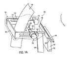
- a system for handling folded sheet material is represented by a handling system 100 as shown in exemplary Figure 1A.
- the exemplary handling system (e.g., handling system 100) can be arranged within a larger apparatus, such as a sheetwise booklet-making device.
- the exemplary handling system includes a collecting device (e.g., collecting device 102) and a rotatable clamping device (e.g., rotatable clamping device 104).
- Collecting device 102 is shown in Figure 1A as being saddle-shaped, and includes a top section shaped as an inverted-V, with a frontside 126, a backside 128, and a supporting edge 146. Frontside 126 and backside 128 represent opposing and different sides of collecting device 102, and can be arranged substantially parallel to each other (while converging at supporting edge 146) or can be alternatively arranged with any acute or obtuse angle between them.
- collecting device 102 be of any shape that is able to support folded sheets of material.
- collecting device 102 can be made of metal, plastic, or any other formable material, and can also be a solid or hollow component.
- Collecting device 102 is pivotable to a supporting edge (e.g., supporting edge 146) relative to rotatable clamping device 104.
- collecting device 102 is rotatable about a pivot axle 122 (by any means for pivoting known in the art) such that supporting edge 146 can be moved away from or towards the axis about which rotatable clamping device 104 rotates.
- collecting device 102 includes a collecting drive 130, which can be in the form of a roller (as shown in Figure 1A) or any other means for driving and securing sheet material 124 against collecting device 102.
- Rotatable clamping device 104 includes a linearly displaceable clamping component (e.g., displaceable clamping component 106) and a fixed clamping component (e.g., fixed clamping component 108).
- the rotatable clamping device of an exemplary embodiment of the present invention is also configured to simultaneously encompass opposing sides of a collecting device. That is, in at least one stage of a sheet delivery operation, clamping components of the rotatable clamping device are positioned such that they exert force (e.g., through different portions of a folded sheet) against opposing sides of a collecting device at the same time.
- rotatable clamping device 104 is shown to be arranged such that displaceable clamping component 106 and fixed clamping component 108 are positioned on (and are able to press against) different and opposing sides of collecting device 102 at the same time.
- sheet material 124 can be secured against opposing sides 126 and 128 of collecting device 102 with the use of rotatable clamping device 104.
- This clamping function is also shown in side view in Figure 2, where a stack of sheet material 224 is secured on opposite sides of collecting device 202 simultaneously by displaceable clamping component 206 and fixed clamping component 208.
- Displaceable clamping component 106 includes drive tires 154 and a rotatable drive shaft 100, drive tires 154 being fixedly mounted on drive shaft 110.
- Drive shaft 110 (and drive tires 154 mounted thereon) can be rotated by a drive shaft motor 118 or, alternatively, by any means for rotating.
- Each drive tire 154 has a circular peripheral surface or, alternatively, can be of any other shape.
- each drive tire 154 can be made of rubber, plastic, or any other formable material.
- Fixed clamping component 108 is arranged in the Figure 1A example as a flat plate, but can alternatively be arranged as any other shape capable of securing sheet material 124 against drive tires 154.
- Fixed clamping component 108 can be a rigid component, and can be made of metal or any other formable material.
- Rotatable clamping device 104 also includes a rotatable arm (e.g., one of arms 112) that rotates to deliver sheet material to collecting device 102.
- fixed clamping component 108 is fixedly mounted at one end of each arm 112, while the other end is pivotably attached to a support 120 at pivot points 134.
- Arms 112 can be arranged as two components (as shown in the figures) or can alternatively be of any number.
- Arm 112 includes guide slots 114 in which drive shaft 110 travels (i.e., in response to an operation of drive shaft motor).
- Guide slots 114 can be arranged linearly (as shown in Figures 1A-1G) or can, alternatively, include any amounts of curvature.
- Arms 112 can be rotated by any means for rotating (e.g., a gear rack and motor assembly).
- displaceable clamping component 106 is moved (via motor 116) towards fixed clamping component 108 along guide slots 114 until sheet material 124 is secured between drive tires 154 and fixed clamping component 108. Once sheet material 124 is clamped against fixed clamping component 108, displaceable clamping component 106 can rotate to drive sheet material 124 along fixed clamping component 108. In this way, rotatable clamping device 104 can be used to both secure and drive sheet material 124.
- displaceable clamping component 106 can be rotatably attached to a lever, which is in turn rotatably attached to an arm such as arm 112. In such a configuration , displaceable clamping component 106 can secure sheet material 124 against fixed clamping component 108 by rotation of the lever. Displaceable clamping component 106 and fixed clamping component 108 can, alternatively, be arranged as any means for clamping of sheet material 124.
- sheet material 124 is a folded sheet, and a leading side and a trailing side of the sheet material (e.g., leading and trailing sides 136 and 138, respectively, in Figure 1C) are respectively delivered to a frontside and a backside of the collecting device (e.g., frontside 126 and backside 128, respectively).
- a leading side and a trailing side of the sheet material e.g., leading and trailing sides 136 and 138, respectively, in Figure 1C
- the collecting device e.g., frontside 126 and backside 128, respectively.
- rotatable clamping device 104 rotates about an axis parallel to supporting edge 146.
- Rotatable clamping device 104 rotates about pivot points 134, which lie along the x-axis shown in Figure 1A, although the present invention is not limited to this orientation.
- pivot points 134 can be arranged along the y-axis in Figure 1A or any other axis.
- collecting device 102 shown in Figure 1A as having the length of its supporting edge 146 arranged along the x-axis, can be arranged in any orientation (e.g., the y-axis or any other axis).
- Rotatable clamping device 104 is shown to extend across the entire width of sheet material 124.
- the distance between arms 112 is greater than the width of sheet material 124 along the x-axis of Figure 1A), where pivot points 134 are located away from the edges of sheet material 124.
- This arrangement leaves a middle area clear for moving the trailing edge of a folded sheet onto collecting device 102.
- rotatable clamping device 104 receives sheet material 124 while in a load position, delivers sheet material 124 as a folded sheet to collecting device 102 while in an unload position, and secures sheet material 124 against collecting device 102 while in a clamping position (this is also shown in Figure 2). That is, these figures represent a movement of rotatable clamping device 104 along a rotational path to deliver sheet material 124 to collecting device 102, such that different portions of the folded sheet (e.g., leading and trailing sides 136 and 138) are respectively delivered to opposing sides of collecting device 102.
- different portions of the folded sheet e.g., leading and trailing sides 136 and 138
- the use of the exemplary rotatable clamping device has the advantage of saving space by directing individual booklet sheets in a non-linear (e.g., rotational) path. As this path is "folded back on itself", a more compact sheet-wise booklet making system is provided. Also, the securing of sheet material 124 against collecting device 102 can be performed by the same component, that is, rotatable clamping device 104.
- Figure 1A illustrates rotatable clamping device 104 in a loading or first position, where sheet material 124 is advanced by an upstream device, such as a main drive, into rotatable clamping device 104.
- sheet material 124 can already include an established fold 150 or can be unfolded.
- displaceable clamping component 106 is positioned away from fixed clamping component 108. This allows sheet material 124 to be advanced into rotatable clamping device 104 and to pass between fixed clamping component 108 and displaceable clamping component 106.
- the exemplary method includes a step of clamping a folded sheet material with a rotatable clamping device (e.g., rotatable clamping device 104).
- a rotatable clamping device e.g., rotatable clamping device 104.
- displaceable clamping component 106 is moved against fixed clamping component 108 (via motor 116), thereby achieving a closed position and clamping a portion of sheet material 124 against fixed clamping component 108.
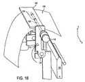
- Arm 112 then rotates about pivot points 134 towards collecting device 102, stopping at an intermediate position while rotatable clamping device 104 maintains a clamping force on sheet material 124.
- a fold 150 (shown in Figure 1C) can be formed in sheet material 124, for example, by a folding apparatus (e.g., if a fold does not already exist on sheet material 124 or if another fold is desired).
- a step of delivering a folded sheet material to a collecting device (e.g., collecting device 102) along an arc established by movement of the rotatable clamping device (e.g., rotatable clamping device 104 in Figure 1C) is also provided, where the folded sheet material is deposited over a supporting edge of the collecting device such that a fold of the folded sheet material is supported by the supporting edge.
- a collecting device e.g., collecting device 102
- the rotatable clamping device e.g., rotatable clamping device 104 in Figure 1C
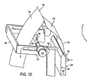
- arms 112 are rotated from the intermediate position (shown in Figure 1B) towards collecting device 102 such that leading side 136 of the clamped and folded sheet material 124 is delivered between collecting device 102 and collecting drive 130.
- drive shaft motor 118 can operate to rotate displaceable clamping component 106 such that leading side 136 of sheet material 124 is advanced toward collecting device 102 and such that leading side 136 passes between collecting device 102 and collecting drive 130 (which is positioned away from collecting device 102).
- drive shaft motor 118 suspends rotation of displaceable clamping component 106 before fold 150 reaches fixed clamping component 108.
- folded sheet material 124 can be alternatively delivered to collecting device 102 in any other manner using rotatable clamping device 104.
- collecting drive 130 is operated to secure leading side 136 against frontside 126.
- motor 116 is operated to move displaceable clamping component 106 away from fixed clamping component 108, thereby releasing sheet material 124 (which is now secured to collecting device 102 by collecting drive 130).
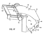
- Arm 112 then rotates away from collecting device 102 and over fold 150 such that fixed clamping component 108 is positioned over trailing side 138.
- Motor 116 operates to secure trailing side 138 against fixed clamping component 108 and to begin advancing sheet material 124 out of rotatable clamping device 104, as shown in Figure 1E. During this step, collecting drive 130 maintains pressure against leading side 136 such that sheet material 124 is secured to frontside 126.
- rotatable clamping device 104 can also be rotated to sweep trailing side 138 against backside 128. As shown in Figures 1A-1F, displaceable clamping component 106 and fixed clamping component 108 are positioned on a same side of collecting device 102 during delivery of sheet material 124.
- a step of clamping the folded sheet material against different sides (e.g., sides 126 and 128) of the collecting device using the rotatable clamping device As shown in Figure 1G, after sheet material 124 is positioned on collecting device 102 such that fold 150 is supported by supporting edge 146, arm 112 rotates towards collecting device 102 until rotatable clamping device 104 clamps sheet material 124 against frontside 126 and backside 128 of collecting device 102.
- Figure 2 illustrates this clamping in side view, where arm 212 is rotated towards collecting device 202 such that rotatable clamping device 204 clamps a stack of sheet material 224 against frontside 226 and backside 228 of collecting device 202.
- displaceable clamping component 106 and fixed clamping component 108 are positioned on different sides of collecting device 102 during the clamping of sheet material 124.
- rotatable clamping device 104 can be positioned such that fixed clamping component 108 secures leading side 136 against frontside 126 while displaceable clamping component 106 secures trailing side 138 against backside 128.
- Such clamping can occur after an alignment or jogging process on collecting device 102.
- a stapler such as stapler 148, can properly staple sheet material 124 when sheet material 124 is clamped against collecting device 102.
- a single component such as rotatable clamping device 104 can be used to deliver sheet material 124 to collecting device 102 and to clamp sheet material 124 against collecting device 102.
- Exemplary embodiments of the present invention can be modified to include features from any or all of the following copending applications, all filed on even date herewith: U.S. Application Serial No. 10/084,460 , entitled “Booklet Maker”, (Trovinger, S.) Attorney Docket No. 10014012-1; and U.S. Application Serial No. 10/084,462, entitled “Pivotable Collecting Device”, (Trovinger, S.) Attorney Docket No. 10015154-1.
Landscapes
- Engineering & Computer Science (AREA)
- Mechanical Engineering (AREA)
- Folding Of Thin Sheet-Like Materials, Special Discharging Devices, And Others (AREA)
- Feeding Of Articles By Means Other Than Belts Or Rollers (AREA)
Applications Claiming Priority (3)
| Application Number | Priority Date | Filing Date | Title |
|---|---|---|---|
| US10/084,459 US6969342B2 (en) | 2002-02-28 | 2002-02-28 | System for handling folded sheet material |
| US84459 | 2002-02-28 | ||
| PCT/US2003/005891 WO2003074289A2 (en) | 2002-02-28 | 2003-02-26 | System for handling folded sheet material |
Publications (2)
| Publication Number | Publication Date |
|---|---|
| EP1480901A2 EP1480901A2 (en) | 2004-12-01 |
| EP1480901B1 true EP1480901B1 (en) | 2007-04-11 |
Family
ID=27753473
Family Applications (1)
| Application Number | Title | Priority Date | Filing Date |
|---|---|---|---|
| EP03743699A Expired - Lifetime EP1480901B1 (en) | 2002-02-28 | 2003-02-26 | System for handling folded sheet material |
Country Status (6)
| Country | Link |
|---|---|
| US (1) | US6969342B2 (enExample) |
| EP (1) | EP1480901B1 (enExample) |
| JP (1) | JP2006507999A (enExample) |
| AU (1) | AU2003225607A1 (enExample) |
| DE (1) | DE60313142T2 (enExample) |
| WO (1) | WO2003074289A2 (enExample) |
Families Citing this family (11)
| Publication number | Priority date | Publication date | Assignee | Title |
|---|---|---|---|---|
| EP1117540B1 (en) * | 1998-09-29 | 2004-03-03 | Hewlett-Packard Company, A Delaware Corporation | Method and apparatus for making booklets |
| US7033123B2 (en) * | 2002-02-28 | 2006-04-25 | Hewlett-Packard Development Company, L.P. | Booklet maker |
| US6981830B2 (en) * | 2002-02-28 | 2006-01-03 | Hewlett-Packard Development Company, L.P. | Pivotable collecting device |
| US6715749B2 (en) | 2002-08-30 | 2004-04-06 | Hewlett-Packard Development Company, L.P. | Booklet maker and method of manufacturing a booklet maker |
| US6796554B2 (en) * | 2002-09-13 | 2004-09-28 | Hewlett-Packard Development Company, L.P. | Apparatus for stacking folded paper sheets |
| US6997450B2 (en) * | 2003-10-09 | 2006-02-14 | Hewlett-Packard Development Company, L.P. | Sheet folding and accumulation system for a booklet maker |
| US20060022393A1 (en) * | 2004-07-30 | 2006-02-02 | Trovinger Steven W | Method of sheet accumulation using sideways saddle motion |
| US20070116543A1 (en) * | 2005-11-23 | 2007-05-24 | Trovinger Steven W | Method and assembly for binding a book with adhesive |
| US7607648B2 (en) * | 2005-11-30 | 2009-10-27 | Hewlett-Packard Development Company, L.P. | Staple hole forming apparatus |
| US7819615B2 (en) | 2005-12-06 | 2010-10-26 | Hewlett-Packard Development | Method and apparatus for finishing sheets for a bound document |
| FR2974827B1 (fr) | 2011-05-06 | 2013-06-07 | Newmat | Outil d'aide au montage et demontage de nappes de fausses parois tendues |
Family Cites Families (20)
| Publication number | Priority date | Publication date | Assignee | Title |
|---|---|---|---|---|
| US4053150A (en) | 1976-03-08 | 1977-10-11 | Cornelius Printing Co. | Folder apparatus |
| US4595187A (en) | 1985-07-26 | 1986-06-17 | Xerox Corporation | Saddle stapler accessory |
| US4891681A (en) | 1988-12-09 | 1990-01-02 | Eastman Kodak Company | Hard copy apparatus for producing center fastened sheet sets |
| US4989850A (en) * | 1989-03-30 | 1991-02-05 | Weller Ronald W | Signature machines |
| ES2076816T3 (es) | 1989-05-25 | 1995-11-01 | Ferag Ag | Instalacion para la agrupacion y el grapado de pliegos impresos plegados. |
| WO1992002888A1 (en) | 1990-07-27 | 1992-02-20 | Ross Harvey M | System and method of manufacturing a single book copy |
| US5152654A (en) | 1990-10-04 | 1992-10-06 | Minnesota Mining And Manufacturing Company | Hot melt adhesive applicator |
| CH682064A5 (enExample) | 1990-10-24 | 1993-07-15 | Kolbus Gmbh & Co Kg | |
| US5100118A (en) * | 1990-10-29 | 1992-03-31 | Am International Incorporated | Sheet material handling apparatus |
| US5377965A (en) | 1993-11-08 | 1995-01-03 | Xerox Corporation | Automatic on-line signature booklets finisher for electronic printers |
| US5452920A (en) | 1994-02-16 | 1995-09-26 | Parker; Kevin P. | Adhesive binding strip and method of making the same |
| US5615871A (en) * | 1996-01-26 | 1997-04-01 | Heidelberg Finishing Systems, Inc. | Sheet material handling apparatus and method |
| US6099225A (en) | 1998-09-29 | 2000-08-08 | Hewlett-Packard Company | Booklet maker |
| EP1117540B1 (en) | 1998-09-29 | 2004-03-03 | Hewlett-Packard Company, A Delaware Corporation | Method and apparatus for making booklets |
| EP1005984B1 (de) | 1998-11-27 | 2004-07-07 | Hunkeler AG Papierverarbeitungsmaschinen | Verfahren zur Herstellung gefalteter, gebundener Druckerzeugnisse sowie Druckerzeugnis |
| US6193458B1 (en) | 1999-04-29 | 2001-02-27 | Jeffrey D. Marsh | System for and method of binding and trimming a perfect bound book |
| US6550756B2 (en) | 2001-03-30 | 2003-04-22 | Hewlett-Packard Company | Apparatus for advancement of paper in a non-linear path |
| US6632061B2 (en) | 2001-03-30 | 2003-10-14 | Hewlett-Packard Development Company, L.P. | Booklet maker with sheet wise trim |
| US6981830B2 (en) | 2002-02-28 | 2006-01-03 | Hewlett-Packard Development Company, L.P. | Pivotable collecting device |
| US7033123B2 (en) | 2002-02-28 | 2006-04-25 | Hewlett-Packard Development Company, L.P. | Booklet maker |
-
2002
- 2002-02-28 US US10/084,459 patent/US6969342B2/en not_active Expired - Fee Related
-
2003
- 2003-02-26 EP EP03743699A patent/EP1480901B1/en not_active Expired - Lifetime
- 2003-02-26 AU AU2003225607A patent/AU2003225607A1/en not_active Abandoned
- 2003-02-26 JP JP2003572776A patent/JP2006507999A/ja active Pending
- 2003-02-26 WO PCT/US2003/005891 patent/WO2003074289A2/en not_active Ceased
- 2003-02-26 DE DE60313142T patent/DE60313142T2/de not_active Expired - Fee Related
Also Published As
| Publication number | Publication date |
|---|---|
| EP1480901A2 (en) | 2004-12-01 |
| US6969342B2 (en) | 2005-11-29 |
| WO2003074289A2 (en) | 2003-09-12 |
| DE60313142T2 (de) | 2008-02-21 |
| WO2003074289A3 (en) | 2004-02-26 |
| US20030162644A1 (en) | 2003-08-28 |
| AU2003225607A8 (en) | 2003-09-16 |
| AU2003225607A1 (en) | 2003-09-16 |
| JP2006507999A (ja) | 2006-03-09 |
| DE60313142D1 (de) | 2007-05-24 |
Similar Documents
| Publication | Publication Date | Title |
|---|---|---|
| EP1372981B1 (en) | Apparatus for advancement of paper in a non-linear path | |
| EP1480901B1 (en) | System for handling folded sheet material | |
| US7033123B2 (en) | Booklet maker | |
| US6447229B1 (en) | Device and method for preparing a book spine for binding | |
| US6981830B2 (en) | Pivotable collecting device | |
| US6796554B2 (en) | Apparatus for stacking folded paper sheets | |
| US7523927B2 (en) | Deliverer module for a press with a displaced paddle wheel for various sized media | |
| CN1880101B (zh) | 纸摞运送装置 | |
| US20050077671A1 (en) | Sheet folding and accumulation system for a booklet maker | |
| JP4074649B2 (ja) | 胴本体と少なくとも1つのグリッパとを備えた折り装置の胴 | |
| CN102107565B (zh) | 装订装置 | |
| JPH10338402A (ja) | シート見当を維持しつつシート材料を減速するための装置 | |
| JP2011136396A (ja) | シート束断裁装置及びこれを備えた製本装置並びに画像形成システム | |
| JP2002012366A (ja) | 膨張プレートを備えた折り胴 | |
| JPH0891622A (ja) | シート状製品を印刷物用の処理装置へ送る搬送装置 | |
| JP2002331771A (ja) | 書籍の背を準備する装置および方法 | |
| JP4401871B2 (ja) | シート処理装置 | |
| BR102012008186A2 (pt) | Dispositivo para a produção de um bloco de livro | |
| JPH03111374A (ja) | 折機のアジロ装置 |
Legal Events
| Date | Code | Title | Description |
|---|---|---|---|
| PUAI | Public reference made under article 153(3) epc to a published international application that has entered the european phase |
Free format text: ORIGINAL CODE: 0009012 |
|
| 17P | Request for examination filed |
Effective date: 20040823 |
|
| AK | Designated contracting states |
Kind code of ref document: A2 Designated state(s): AT BE BG CH CY CZ DE DK EE ES FI FR GB GR HU IE IT LI LU MC NL PT SE SI SK TR |
|
| AX | Request for extension of the european patent |
Extension state: AL LT LV MK RO |
|
| GRAP | Despatch of communication of intention to grant a patent |
Free format text: ORIGINAL CODE: EPIDOSNIGR1 |
|
| GRAS | Grant fee paid |
Free format text: ORIGINAL CODE: EPIDOSNIGR3 |
|
| GRAA | (expected) grant |
Free format text: ORIGINAL CODE: 0009210 |
|
| AK | Designated contracting states |
Kind code of ref document: B1 Designated state(s): DE FR GB |
|
| REG | Reference to a national code |
Ref country code: GB Ref legal event code: FG4D |
|
| REF | Corresponds to: |
Ref document number: 60313142 Country of ref document: DE Date of ref document: 20070524 Kind code of ref document: P |
|
| ET | Fr: translation filed | ||
| PLBE | No opposition filed within time limit |
Free format text: ORIGINAL CODE: 0009261 |
|
| STAA | Information on the status of an ep patent application or granted ep patent |
Free format text: STATUS: NO OPPOSITION FILED WITHIN TIME LIMIT |
|
| 26N | No opposition filed |
Effective date: 20080114 |
|
| PGFP | Annual fee paid to national office [announced via postgrant information from national office to epo] |
Ref country code: GB Payment date: 20090227 Year of fee payment: 7 |
|
| PGFP | Annual fee paid to national office [announced via postgrant information from national office to epo] |
Ref country code: DE Payment date: 20090331 Year of fee payment: 7 |
|
| PGFP | Annual fee paid to national office [announced via postgrant information from national office to epo] |
Ref country code: FR Payment date: 20090217 Year of fee payment: 7 |
|
| GBPC | Gb: european patent ceased through non-payment of renewal fee |
Effective date: 20100226 |
|
| REG | Reference to a national code |
Ref country code: FR Ref legal event code: ST Effective date: 20101029 |
|
| PG25 | Lapsed in a contracting state [announced via postgrant information from national office to epo] |
Ref country code: FR Free format text: LAPSE BECAUSE OF NON-PAYMENT OF DUE FEES Effective date: 20100301 |
|
| PG25 | Lapsed in a contracting state [announced via postgrant information from national office to epo] |
Ref country code: DE Free format text: LAPSE BECAUSE OF NON-PAYMENT OF DUE FEES Effective date: 20100901 |
|
| PG25 | Lapsed in a contracting state [announced via postgrant information from national office to epo] |
Ref country code: GB Free format text: LAPSE BECAUSE OF NON-PAYMENT OF DUE FEES Effective date: 20100226 |