EP1480295A2 - Hermetically sealed terminal for electrical device - Google Patents
Hermetically sealed terminal for electrical device Download PDFInfo
- Publication number
- EP1480295A2 EP1480295A2 EP04010503A EP04010503A EP1480295A2 EP 1480295 A2 EP1480295 A2 EP 1480295A2 EP 04010503 A EP04010503 A EP 04010503A EP 04010503 A EP04010503 A EP 04010503A EP 1480295 A2 EP1480295 A2 EP 1480295A2
- Authority
- EP
- European Patent Office
- Prior art keywords
- terminal contact
- electronic component
- assembly
- opening
- insulator
- Prior art date
- Legal status (The legal status is an assumption and is not a legal conclusion. Google has not performed a legal analysis and makes no representation as to the accuracy of the status listed.)
- Granted
Links
Images

Classifications
-
- H—ELECTRICITY
- H01—ELECTRIC ELEMENTS
- H01R—ELECTRICALLY-CONDUCTIVE CONNECTIONS; STRUCTURAL ASSOCIATIONS OF A PLURALITY OF MUTUALLY-INSULATED ELECTRICAL CONNECTING ELEMENTS; COUPLING DEVICES; CURRENT COLLECTORS
- H01R13/00—Details of coupling devices of the kinds covered by groups H01R12/70 or H01R24/00 - H01R33/00
- H01R13/46—Bases; Cases
- H01R13/52—Dustproof, splashproof, drip-proof, waterproof, or flameproof cases
- H01R13/521—Sealing between contact members and housing, e.g. sealing insert
-
- H—ELECTRICITY
- H01—ELECTRIC ELEMENTS
- H01M—PROCESSES OR MEANS, e.g. BATTERIES, FOR THE DIRECT CONVERSION OF CHEMICAL ENERGY INTO ELECTRICAL ENERGY
- H01M50/00—Constructional details or processes of manufacture of the non-active parts of electrochemical cells other than fuel cells, e.g. hybrid cells
- H01M50/10—Primary casings; Jackets or wrappings
- H01M50/172—Arrangements of electric connectors penetrating the casing
-
- H—ELECTRICITY
- H01—ELECTRIC ELEMENTS
- H01M—PROCESSES OR MEANS, e.g. BATTERIES, FOR THE DIRECT CONVERSION OF CHEMICAL ENERGY INTO ELECTRICAL ENERGY
- H01M50/00—Constructional details or processes of manufacture of the non-active parts of electrochemical cells other than fuel cells, e.g. hybrid cells
- H01M50/10—Primary casings; Jackets or wrappings
- H01M50/183—Sealing members
- H01M50/184—Sealing members characterised by their shape or structure
-
- H—ELECTRICITY
- H01—ELECTRIC ELEMENTS
- H01M—PROCESSES OR MEANS, e.g. BATTERIES, FOR THE DIRECT CONVERSION OF CHEMICAL ENERGY INTO ELECTRICAL ENERGY
- H01M50/00—Constructional details or processes of manufacture of the non-active parts of electrochemical cells other than fuel cells, e.g. hybrid cells
- H01M50/10—Primary casings; Jackets or wrappings
- H01M50/183—Sealing members
- H01M50/186—Sealing members characterised by the disposition of the sealing members
- H01M50/188—Sealing members characterised by the disposition of the sealing members the sealing members being arranged between the lid and terminal
-
- H—ELECTRICITY
- H01—ELECTRIC ELEMENTS
- H01M—PROCESSES OR MEANS, e.g. BATTERIES, FOR THE DIRECT CONVERSION OF CHEMICAL ENERGY INTO ELECTRICAL ENERGY
- H01M50/00—Constructional details or processes of manufacture of the non-active parts of electrochemical cells other than fuel cells, e.g. hybrid cells
- H01M50/10—Primary casings; Jackets or wrappings
- H01M50/183—Sealing members
- H01M50/19—Sealing members characterised by the material
- H01M50/198—Sealing members characterised by the material characterised by physical properties, e.g. adhesiveness or hardness
-
- H—ELECTRICITY
- H01—ELECTRIC ELEMENTS
- H01M—PROCESSES OR MEANS, e.g. BATTERIES, FOR THE DIRECT CONVERSION OF CHEMICAL ENERGY INTO ELECTRICAL ENERGY
- H01M50/00—Constructional details or processes of manufacture of the non-active parts of electrochemical cells other than fuel cells, e.g. hybrid cells
- H01M50/50—Current conducting connections for cells or batteries
- H01M50/543—Terminals
- H01M50/552—Terminals characterised by their shape
-
- H—ELECTRICITY
- H01—ELECTRIC ELEMENTS
- H01M—PROCESSES OR MEANS, e.g. BATTERIES, FOR THE DIRECT CONVERSION OF CHEMICAL ENERGY INTO ELECTRICAL ENERGY
- H01M2220/00—Batteries for particular applications
- H01M2220/20—Batteries in motive systems, e.g. vehicle, ship, plane
Definitions
- This invention relates generally to electro-mechanical parts, and in particular, to a hermetically sealed terminal for functionally linking the interior and the exterior of an electro-mechanical device particularly adapted for use in an aerospace vehicle.
- electro-mechanical parts are used for countless applications in a wide variety of environments. These electro-mechanical parts often contain electronic devices having electrical circuits that are sensitive to the environments in which the electro-mechanical parts are exposed.
- many electronic devices include housings for the circuits that hermetically seal the interiors of the electronic devices from the exteriors thereof so as to limit the exposure of the components of the electrical circuits to the environment. It can be appreciated that the electrical circuit within the housing of an electronic device must be functionally linked to electrical and/or mechanical parts outside of the housing by a terminal.
- the terminal in order to hermetically seal an electronic device having a terminal extending through the housing thereof, the terminal would be either soldered or welded to the housing so as to prevent leakage into the device from about the terminal.
- the soldering or welding of the terminal to the housing of the electronic device has certain inherent weaknesses when the electronic device is used in an application such as an aerospace vehicle.
- the solder or weld used to mount the terminal can be sensitive to the abrupt temperature changes that occur as the aerospace vehicle cycles between ground and a high altitude. As a result, cracks may occur in the solder or weld thereby resulting is a loss of the seal, a reduction of insulation resistance and a reduction of the dielectric withstanding voltage.
- the repeated expansion and contraction of the housing of the electronic device due to repeated pressure changes that occur as the aerospace vehicle cycles between ground and a high altitude may also cause the solder or weld to crack. This, in turn, exposes the electrical circuit within the housing to the external environment, which may cause the premature failure of the electrical circuit.
- a terminal contact assembly for mounting to an electronic component defining an interior and exterior and having an opening therebetween.
- the contact assembly includes a terminal contact positionable within the opening of the electronic component.
- the terminal contact having inner and outer ends.
- a deformable o-ring is positioned about the terminal contact within the opening through the electronic component for hermetically sealing the interior of the electronic component.
- the assembly further includes an inner insulator positioned within the interior of the electronic component adjacent the o-ring and an outer insulator extending about the terminal contact.
- the inner insulator includes an enlarged head positioned on the interior of the electronic component and a neck extending therefrom. The neck of the inner insulator is receivable in the opening of the electronic component.
- the terminal contact includes a radially extending disc projecting therefrom within the interior of the electronic component.
- a nut is threadable on the inner end of the terminal contact. The nut compresses the inner and outer insulators between the disc and the nut so as to generate a deforming force on the o-ring.
- a terminal contact assembly for mounting to an electronic component.
- the electronic component defines an interior and an exterior, and has an opening therebetween.
- the contact assembly includes a terminal contact extending through the opening in the electronic component.
- the terminal contact has inner and outer ends.
- a deformable o-ring is positioned about the terminal contact within the opening through the electronic component.
- a torque generating structure generates a deformable force on the o-ring such that the o-ring seals the opening through the electronic component.
- the assembly may also include an inner insulator positioned within the interior of the electronic component adjacent the o-ring.
- An outer insulator extends about the terminal contact such that the inner insulator and the outer insulator capture the o-ring therebetween.
- the inner insulator includes an enlarged head positioned in the interior of the electronic component and a neck extending therefrom. The neck is receivable in the opening in the in the electronic component.
- the terminal contact include a radially extending disc projecting therefrom.
- a torque generating structure such as a nut, is threadable on the inner end of the terminal contact for compressing the inner and outer insulators between the disc and the nut. It is contemplated form the inner and outer insulator from a high friction resistance material such as polyethermide.
- a terminal contact assembly for mounting to an electronic component.
- the electronic component has an inner surface defining an interior, an exterior surface and an opening therebetween.
- the contact assembly includes a terminal contact extending through the opening of the electronic component.
- the terminal contact has an inner end within the interior of the electronic component and an outer end.
- a deformable o-ring is positioned about the terminal contact within the opening through the electronic component.
- An outer insulator is positioned adjacent the exterior surface of the electronic component.
- An inner insulator extends about the terminal contact.
- the inner insulator includes a base portion and a neck portion extending into the opening.
- a torque generating structure generates a deformable force on the o-ring such that the o-ring seals the opening through the electronic component.
- the terminal contact includes a radially extending disc projecting therefrom.
- the torque generating structure includes a nut threadable on the inner end of the terminal for compressing the inner and outer insulators between the disc and the nut.
- the inner and outer insulator is formed from a high friction resistance material such as polyethermide.
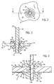
- a terminal contact assembly in accordance with the present invention is generally designated by the reference numeral 10.
- the terminal contact assembly 10 is intended to be mounted within an opening 12 extending through a housing 14 of an electrical component that is particularly adapted to be used in an aerospace vehicle.
- housing 14 includes inner surface 16 defining the interior of the electrical component and outer surface 18 communicating with the environment external of housing 14.
- Terminal contact assembly 10 includes terminal 20 having outer end 22 and inner end 24.
- Terminal 20 is defined by a generally cylindrical outer surface 26.
- Disc 28 projects radially from outer surface 26 of terminal 20 and terminates at a radially outer edge 30.
- Outer edge 30 of disc 28 extends between first and second faces 32 and 34.
- Outer surface 26 of terminal 20 includes a threaded outer portion 26a extending from outer end 22 of terminal 20 to face 32 of disc 28.
- outer surface 26 of terminal 20 includes a threaded inner portion 26b that extends between inner end 24 of terminal 20 and thread-free portion 26c of outer surface 26 of terminal 20. Thread free portion 26c of outer surface 26 of terminal 20 extends between inner portion 26b of outer surface 26 of terminal 20 and face 34 of disc 30.
- Terminal contact assembly 10 further includes a generally disc-shaped outer insulator 36 having inner face 38 engageable with outer surface 18 of housing 14 and outer face 40 engageable with face 34 of disc 28.
- Inner face 38 of outer insulator 36 and outer face 40 of outer insulator 36 are interconnected by radially outer edge 42 and by radially inner edge 44.
- Inner edge 44 of outer insulator 36 defines an opening 46 through outer insulator 36 for receiving terminal 20 therethrough. It is contemplated that the diameter of opening 46 in outer insulator 36 is generally equal to the diameter of terminal 20 and that outer insulator 36 be formed from a high friction resistance material such as polyethermide.
- Terminal contact assembly 10 further includes o-ring 48 and inner insulator 50. It is contemplated to form O-ring from a synthetic rubber and to form insulator 50 from a high friction resistance material such as polyethermide.
- O-ring 48 has an inner diameter generally equal to the diameter of terminal 20 and an outer diameter generally equal to the diameter of opening 12 in housing 14.
- Inner insulator 50 includes a disc portion 52 defined by inner face 54 and outer face 56 that is engageable with inner surface 16 of housing 14.
- Inner face 54 and outer face 56 of disc portion 52 of inner insulator 50 are interconnected by radially outer edge 58.
- Neck 60 extends from outer face 56 of disc portion 58 of inner insulator 50 and has an outer surface 62.
- Neck 60 terminates at terminal end 64 and has a diameter generally equal to the diameter of opening 12 through housing 14. Opening 66 extends through inner insulator 50 between inner face 54 of disc portion 52 and terminal end 64 of neck portion 62. Opening 66 through inner insulator 50 has a diameter generally equal to the diameter of terminal 20.
- Nut 68 is receivable an inner portion 24 of terminal 20 and includes a generally flat insulation engaging face 70 for engaging inner face 54 of disc portion 52 of inner insulator 50, as hereinafter described.
- inner end 24 of terminal 20 is inserted through opening 46 in outer insulator 36 such that outer face 40 of outer insulator 36 engages face 34 of disc 30. Thereafter, inner end 24 of terminal 20 is inserted through opening 12 in housing 14 such that inner face 38 of outer insulator 36 engages outer face 18 of housing 14. As described, outer insulator 36 is captured on thread-free portion 26c of outer surface 26 of terminal 20 between disc 30 and housing 14.
- o-ring 48 With terminal 20 extending through opening 12 in housing 14, o-ring 48 is slid over inner end 24 of terminal 20 into opening 12 in housing 14 such that the inner diameter of o-ring 48 sealably engages thread-free portion 26c of outer surface 26 of terminal 20 and such that outer diameter of o-ring 48 sealably engages housing 14.
- inner insulator 50 is slid over inner end 24 of terminal 20 such that terminal 30 extends through opening 66 in inner insulator 50.
- Nut 68 is threaded onto inner end 24 of terminal 20 so as to urge neck 60 of inner insulator 50 into engagement with o-ring 48 in opening 12 through housing 14.
- o-ring 48 is compressed between inner face 38 of outer insulator 36 and terminal end 64 of neck 60 of inner insulator 50.
- the shape of o-ring 48 deforms such that o-ring 48 hermetically seals the interior of housing 14 from the environment outside of housing 14.
- a low level of assembly torque may be utilized to thread nut 68 onto inner end 24 of terminal 20. This, in turn, reduces the time necessary to mount the terminal contact assembly to housing 14.
- the terminal contact assembly 10 of the present invention is capable of better absorbing the mechanical stresses to which an electrical device may be exposed then prior art rigid interlocks produced by soldering, brazing or welding a terminal contact assembly in position.
- Terminal contact assembly 72 includes common components as terminal contact assembly 10, and as such, common reference characters are used hereinafter to refer to these common components. Similar to terminal contact assembly 10, it is intended that terminal contact assembly 72 be mounted within opening 12 through housing 14.
- Terminal contact assembly 72 includes a generally disc shaped outer insulator 74 having an outer face76 and an inner face 78 engageable with outer surface 18 of housing 14. Outer face 76 and inner face 78 of outer insulator 74 are interconnected by a radially outer edge 80 and a radially inner edge 82 that defines an opening therethrough.
- Recessed surface 84 extends between inner edge 82 and inner face 78 of outer insulator 74 for receiving o-ring 86 therein.
- O-ring 86 includes a generally conical outer surface 88 engageable with recess surface 84 of outer insulator 74 and an inner face 90.
- O-ring 86 has an opening 92 therethrough having a diameter generally equal to the diameter of terminal 20.
- O-ring 86 has an outer diameter greater than the diameter of opening 12 through housing 14, for reasons hereinafter described.
- Terminal contact assembly 72 further includes inner insulator 94.
- Inner insulator 94 includes a disc portion 96 having an inner face 98 and an outer face 100 engageable with inner face 16 of housing 14.
- a generally cylindrical inner neck 101 extends from inner face 98 of disc portion 96 and terminates at terminal end 102.
- outer neck 104 extends from outer face 100 of disc portion 96 of inner insulator 94 and terminates at terminal end 106.
- Neck 104 has an outer diameter generally equal to the diameter of opening 12 through housing 14.
- Inner insulator 94 further includes an inner surface 108 that defines a passageway 108 extending through inner insulator 94 from terminal end 102 of inner neck 100 to terminal end 106 of outer neck 104 to accommodate terminal 20. It is contemplated to provide threads on inner surface 108 of inner insulator 94 that form a mating relationship with the threads on inner portion 26b of outer surface 26 of terminal 20, for reasons hereinafter described.
- inner end 24 of terminal 20 is inserted through opening in outer insulator 74 such that outer face of outer insulator engages face 34 of disc 30.
- Inner end 24 of terminal 20 is then inserted through opening 92 in o-ring 86 such that outer surface 88 of o-ring 86 engages recessed surface 84 of outer insulator 74.
- inner end 24 of terminal 20 is inserted through opening 12 in housing 14 such that inner face 78 of outer insulator 74 engages outer surface 18 of housing 14 and such that o-ring 86 overlaps opening 12 through housing 14.
- inner insulator 94 With terminal 20 extending through opening 12 in housing 14, inner insulator 94 is threaded onto inner portion 26b of outer surface 26 of terminal 20. As inner insulator 94 is threaded further onto terminal 20, o-ring 86 is compressed between recessed surface 84 of outer insulator 74 and outer face 100 of inner insulator 94 such that o-ring 48 deforms within opening 12 and hermetically seals the interior of housing 14 from the environment outside of housing 14.
- a low level of assembly torque may be utilized to thread inner insulator 94 onto inner end 24 of terminal 20.
- terminal contact assembly 10 be mounted to an electronic component particularly adapted for use in an aerospace vehicle. It is intended that terminal contact assembly 10 hermetically seal the interior of housing 14 from the exterior thereof when the electronic component is exposed to temperatures ranging from -55° Celsius to 125° Celsius. Further, it is intended that terminal contact assembly 10 maintain its seal within opening 12 in housing 14 as the aerospace vehicle repeatedly cycles between ground and altitudes of up to 80,000 feet above sea level.
Landscapes
- Chemical & Material Sciences (AREA)
- Chemical Kinetics & Catalysis (AREA)
- Electrochemistry (AREA)
- General Chemical & Material Sciences (AREA)
- Connections Arranged To Contact A Plurality Of Conductors (AREA)
- Connector Housings Or Holding Contact Members (AREA)
Abstract
Description
Claims (18)
- A terminal contact assembly (10) for mounting to an electronic component adapted for use in an aerospace vehicle, the electronic component defining an interior and an exterior and having opening (12) therebetween, the contact assembly comprising:a terminal contact (20) positionable within the opening (12) in the electronic component, the terminal contact having inner and outer ends (22 and 24); anda deformable o-ring (48) positioned about the terminal contact within the opening (12) through the electronic component for hermetically sealing the interior of the electronic component.
- The assembly of claim 1 further comprising an inner insulator (50) positioned within the interior of the electronic component adjacent the o-ring (48).
- The assembly of claim 2 further comprising an outer insulator (36) extending about the terminal contact (20).
- The assembly of claim 3 wherein the inner insulator (50) includes an enlarged head (52) positioned on the exterior of the electronic component and neck (62) extending therefrom, the neck (62) being receivable in the opening (12) in the electronic component.
- The assembly of claim 1 wherein the terminal contact (20) includes a radially extending disc (28) projecting therefrom.
- The assembly of claim 5 further comprising insulation (36, 50) provided on opposite sides of the o-ring (48).
- The assembly of claim 6 further comprising a torque generating structure (68) engageable with the insulation for generating a deforming force on the o-ring (48).
- The assembly of claim 7 wherein the torque generating structure (68) includes a nut threadable on the inner end (24) of the terminal contact (20) for compressing the insulation between the disc (28) and the nut (68).
- A terminal contact assembly (10) for mounting to an electronic component defining an interior and an exterior and having opening (12) therebetween, the contact assembly comprising:a terminal contact (20) extending through the opening (12) in the electronic component, the terminal contact having inner (24) and outer (22) ends;a deformable o-ring (48) positioned about the terminal contact (20) within the opening (12) through the electronic component; anda torque generating structure (68) for generating a deforming force on the o-ring (48) such that the o-ring (48) seals the opening (12) through of the electronic component.
- The assembly of claim 9 further comprising:an inner insulator (50) positioned within the interior of the electronic component adjacent the o-ring (48); andan outer insulator extending about the terminal contact (20), the outer insulator (36) and the inner insulator (50) capture the o-ring (48) therebetween.
- The assembly of claim 10 wherein the inner insulator (50) includes an enlarged head (52) positioned on the exterior of the electronic component and neck (62) extending therefrom, the neck (62) being receivable in the opening (12) in the electronic component.
- The assembly of claim 10 wherein the terminal contact (20) includes a radially extending disc (28) projecting therefrom.
- The assembly of claim 12 wherein the torque generating structure (68) includes a nut threadable on the inner end (24) of the terminal contact (20) for compressing the inner (50) and outer (36 ) insulators between the disc (28) and the nut (48).
- The assembly of claim 10 wherein the inner insulator (50) is formed from a high friction resistance material.
- A terminal contact assembly (10) for mounting to an electronic component, the electronic component having an inner surface defining an interior, an exterior surface and an opening (12) therebetween, the contact assembly comprising:a terminal contact (20) extending through the opening (12) in the electronic component, the terminal contact (20) having inner end (24) within the interior of the electrical component and an outer end (22);a deformable seal (48) positioned about the terminal contact (20) within the opening (12) through the electronic component;an outer insulator (36) positioned adjacent the interior surface of the electronic component;an inner insulator (50) extending about the terminal contact (20), the inner insulator (50) including a base portion (52) and a neck portion (62) extending into the opening (12); anda torque generating structure (68) for generating a deforming force on the seal (48) such that the seal (48) seals the opening (12) through the electronic component.
- The assembly of claim 15 wherein the terminal contact (20) includes a radially extending disc (28) projecting therefrom.
- The assembly of claim 16 wherein the torque generating structure (68) includes a nut threadable on the inner end (24) of the terminal contact (20) for compressing the inner (50) and outer (36) insulators between the disc (28) and the nut (68).
- The assembly of claim 15 wherein the inner insulator (50) is formed from a high friction resistance material.
Applications Claiming Priority (2)
| Application Number | Priority Date | Filing Date | Title |
|---|---|---|---|
| US440602 | 2003-05-19 | ||
| US10/440,602 US6899570B2 (en) | 2003-05-19 | 2003-05-19 | Hermetically sealed terminal for electrical device |
Publications (3)
| Publication Number | Publication Date |
|---|---|
| EP1480295A2 true EP1480295A2 (en) | 2004-11-24 |
| EP1480295A3 EP1480295A3 (en) | 2006-07-05 |
| EP1480295B1 EP1480295B1 (en) | 2012-07-25 |
Family
ID=33097941
Family Applications (1)
| Application Number | Title | Priority Date | Filing Date |
|---|---|---|---|
| EP04010503A Expired - Lifetime EP1480295B1 (en) | 2003-05-19 | 2004-05-03 | Hermetically sealed terminal for electrical device |
Country Status (4)
| Country | Link |
|---|---|
| US (1) | US6899570B2 (en) |
| EP (1) | EP1480295B1 (en) |
| JP (1) | JP4482870B2 (en) |
| CA (1) | CA2467384A1 (en) |
Cited By (2)
| Publication number | Priority date | Publication date | Assignee | Title |
|---|---|---|---|---|
| WO2000065812A1 (en) | 1999-04-27 | 2000-11-02 | Telia Ab | A method and system adapted to provide value added services to mobile telephony subscribers |
| FR3141813A1 (en) * | 2022-11-04 | 2024-05-10 | Safran Electrical & Power | Wall crossing system |
Families Citing this family (10)
| Publication number | Priority date | Publication date | Assignee | Title |
|---|---|---|---|---|
| DE102004040072B4 (en) * | 2004-08-18 | 2009-06-25 | Continental Automotive Gmbh | Sealing arrangement of a piezoelectric actuator and method for sealing a piezoelectric actuator |
| DE102006029966B4 (en) * | 2006-06-29 | 2010-04-22 | Continental Automotive Gmbh | Sealing arrangement of a piezoelectric actuator for a fuel injection valve of an internal combustion engine |
| DE102008025955B3 (en) * | 2008-05-30 | 2009-12-03 | Concentrix Solar Gmbh | Electric, water vapor diffusion-proof connector |
| CN104396007B (en) * | 2012-11-29 | 2017-06-13 | 京瓷株式会社 | Electronic unit receiving container and electronic installation |
| CN103490196B (en) * | 2013-09-02 | 2015-12-23 | 熊猫电子集团有限公司 | Active antenna waterproof radio-frequency connector for ship |
| DE102013217977A1 (en) * | 2013-09-09 | 2015-03-12 | Brose Fahrzeugteile GmbH & Co. Kommanditgesellschaft, Würzburg | Arrangement for producing an electrical contact, electric drive, and method |
| US9368908B2 (en) | 2014-04-03 | 2016-06-14 | Akron Brass Company | Electrical terminal assembly |
| DE102015223909A1 (en) * | 2015-12-01 | 2017-06-01 | Brose Fahrzeugteile GmbH & Co. Kommanditgesellschaft, Würzburg | System of a first component with a conductor and a partition element and a method of manufacturing the system |
| JP7192651B2 (en) * | 2019-05-10 | 2022-12-20 | 株式会社オートネットワーク技術研究所 | electric junction box |
| CN118315857B (en) * | 2024-06-05 | 2024-08-06 | 深圳市国天电子股份有限公司 | High-voltage via connector |
Family Cites Families (9)
| Publication number | Priority date | Publication date | Assignee | Title |
|---|---|---|---|---|
| US949726A (en) * | 1908-12-07 | 1910-02-15 | P R Mfg Company | Electric insulator. |
| US2245918A (en) * | 1939-05-31 | 1941-06-17 | John W Hobbs Corp | Mounting for clock movement |
| US2418729A (en) * | 1945-10-01 | 1947-04-08 | William J Schemers | Auxiliary terminal for sealed-in motor compressor units |
| US2425404A (en) * | 1946-06-10 | 1947-08-12 | Touborg Jens | Electric terminal for hermetic compressors |
| US2823251A (en) * | 1954-04-12 | 1958-02-11 | Richard U Clark | Terminals and method of making same |
| CH358482A (en) * | 1958-11-28 | 1961-11-30 | Haeny & Cie | Liquid- and gas-tight electrical bushing suitable for temperatures up to at least 400 C. |
| GB1099548A (en) * | 1965-11-25 | 1968-01-17 | Bir Vac Ltd | A device for extending through the wall of a vacuum vessel |
| FR2752089B1 (en) * | 1996-07-30 | 1998-09-04 | Accumulateurs Fixes | CYLINDRICAL ELECTROCHEMICAL GENERATOR |
| JP3717684B2 (en) * | 1998-10-30 | 2005-11-16 | 三洋電機株式会社 | Cylindrical secondary battery |
-
2003
- 2003-05-19 US US10/440,602 patent/US6899570B2/en not_active Expired - Lifetime
-
2004
- 2004-05-03 EP EP04010503A patent/EP1480295B1/en not_active Expired - Lifetime
- 2004-05-14 JP JP2004144980A patent/JP4482870B2/en not_active Expired - Lifetime
- 2004-05-17 CA CA002467384A patent/CA2467384A1/en not_active Abandoned
Cited By (3)
| Publication number | Priority date | Publication date | Assignee | Title |
|---|---|---|---|---|
| WO2000065812A1 (en) | 1999-04-27 | 2000-11-02 | Telia Ab | A method and system adapted to provide value added services to mobile telephony subscribers |
| FR3141813A1 (en) * | 2022-11-04 | 2024-05-10 | Safran Electrical & Power | Wall crossing system |
| WO2024094934A1 (en) * | 2022-11-04 | 2024-05-10 | Safran Electrical & Power | Assembly comprising a wall feed-through system |
Also Published As
| Publication number | Publication date |
|---|---|
| JP2004349252A (en) | 2004-12-09 |
| EP1480295B1 (en) | 2012-07-25 |
| US6899570B2 (en) | 2005-05-31 |
| JP4482870B2 (en) | 2010-06-16 |
| EP1480295A3 (en) | 2006-07-05 |
| CA2467384A1 (en) | 2004-11-19 |
| US20040235363A1 (en) | 2004-11-25 |
Similar Documents
| Publication | Publication Date | Title |
|---|---|---|
| US6899570B2 (en) | Hermetically sealed terminal for electrical device | |
| WO2011104860A1 (en) | Pressure sensor module and pressure detection device | |
| RU2665351C2 (en) | Wire sealing for the detector unit | |
| EP3805753B1 (en) | Explosion proof piezoelectric ultrasonic detector | |
| US5026302A (en) | Connector | |
| JP5362342B2 (en) | Pressure detection device | |
| US20170005432A1 (en) | Peripheral wedge seal member | |
| CN102891395A (en) | Sealing connector used in high temperature and high pressure environment | |
| US9257783B2 (en) | Hermetic cable adapter | |
| US20100066026A1 (en) | Main seal system and method for use in an electronic device | |
| CN114361895B (en) | High-voltage-resistant socket assembly with sealing switching function | |
| US12401143B2 (en) | High-current electrical pass through standoff connection for electronic box | |
| CN216598134U (en) | Fuzz button radio frequency coaxial connector | |
| US4509808A (en) | High voltage, gas tight connector | |
| KR20150014913A (en) | Device with an elastic sealing part arranged between a first component and a second component, and method for producing such a device | |
| US5981103A (en) | Assemblies of electronic devices and flexible containers therefor | |
| EP0971445A2 (en) | Encircled electrical compression contact | |
| US20060046635A1 (en) | Venting member | |
| JP3419048B2 (en) | Airtight terminal | |
| CN113207320A (en) | Connector assembly | |
| JPS63252369A (en) | Terminal or connector |
Legal Events
| Date | Code | Title | Description |
|---|---|---|---|
| PUAI | Public reference made under article 153(3) epc to a published international application that has entered the european phase |
Free format text: ORIGINAL CODE: 0009012 |
|
| AK | Designated contracting states |
Kind code of ref document: A2 Designated state(s): AT BE BG CH CY CZ DE DK EE ES FI FR GB GR HU IE IT LI LU MC NL PL PT RO SE SI SK TR |
|
| AX | Request for extension of the european patent |
Extension state: AL HR LT LV MK |
|
| PUAL | Search report despatched |
Free format text: ORIGINAL CODE: 0009013 |
|
| AK | Designated contracting states |
Kind code of ref document: A3 Designated state(s): AT BE BG CH CY CZ DE DK EE ES FI FR GB GR HU IE IT LI LU MC NL PL PT RO SE SI SK TR |
|
| AX | Request for extension of the european patent |
Extension state: AL HR LT LV MK |
|
| RIC1 | Information provided on ipc code assigned before grant |
Ipc: H01R 13/52 20060101AFI20040723BHEP Ipc: H01B 17/30 20060101ALI20060601BHEP |
|
| 17P | Request for examination filed |
Effective date: 20061221 |
|
| AKX | Designation fees paid |
Designated state(s): DE SE |
|
| 17Q | First examination report despatched |
Effective date: 20070606 |
|
| GRAP | Despatch of communication of intention to grant a patent |
Free format text: ORIGINAL CODE: EPIDOSNIGR1 |
|
| RIN1 | Information on inventor provided before grant (corrected) |
Inventor name: AFANASIEV, MICHAEL E. Inventor name: EVANS, ROBERT J. Inventor name: KITTS, KARL L. |
|
| GRAS | Grant fee paid |
Free format text: ORIGINAL CODE: EPIDOSNIGR3 |
|
| GRAA | (expected) grant |
Free format text: ORIGINAL CODE: 0009210 |
|
| AK | Designated contracting states |
Kind code of ref document: B1 Designated state(s): DE SE |
|
| REG | Reference to a national code |
Ref country code: DE Ref legal event code: R096 Ref document number: 602004038623 Country of ref document: DE Effective date: 20120913 |
|
| REG | Reference to a national code |
Ref country code: SE Ref legal event code: TRGR |
|
| PLBE | No opposition filed within time limit |
Free format text: ORIGINAL CODE: 0009261 |
|
| STAA | Information on the status of an ep patent application or granted ep patent |
Free format text: STATUS: NO OPPOSITION FILED WITHIN TIME LIMIT |
|
| 26N | No opposition filed |
Effective date: 20130426 |
|
| REG | Reference to a national code |
Ref country code: DE Ref legal event code: R097 Ref document number: 602004038623 Country of ref document: DE Effective date: 20130426 |
|
| PGFP | Annual fee paid to national office [announced via postgrant information from national office to epo] |
Ref country code: SE Payment date: 20200427 Year of fee payment: 17 |
|
| PGFP | Annual fee paid to national office [announced via postgrant information from national office to epo] |
Ref country code: DE Payment date: 20210421 Year of fee payment: 18 |
|
| REG | Reference to a national code |
Ref country code: SE Ref legal event code: EUG |
|
| PG25 | Lapsed in a contracting state [announced via postgrant information from national office to epo] |
Ref country code: SE Free format text: LAPSE BECAUSE OF NON-PAYMENT OF DUE FEES Effective date: 20210504 |
|
| REG | Reference to a national code |
Ref country code: DE Ref legal event code: R119 Ref document number: 602004038623 Country of ref document: DE |
|
| PG25 | Lapsed in a contracting state [announced via postgrant information from national office to epo] |
Ref country code: DE Free format text: LAPSE BECAUSE OF NON-PAYMENT OF DUE FEES Effective date: 20221201 |