EP1480098B1 - Regulateur de pression - Google Patents
Regulateur de pression Download PDFInfo
- Publication number
- EP1480098B1 EP1480098B1 EP04006511A EP04006511A EP1480098B1 EP 1480098 B1 EP1480098 B1 EP 1480098B1 EP 04006511 A EP04006511 A EP 04006511A EP 04006511 A EP04006511 A EP 04006511A EP 1480098 B1 EP1480098 B1 EP 1480098B1
- Authority
- EP
- European Patent Office
- Prior art keywords
- valve
- leaf spring
- seat carrier
- seat
- pressure
- Prior art date
- Legal status (The legal status is an assumption and is not a legal conclusion. Google has not performed a legal analysis and makes no representation as to the accuracy of the status listed.)
- Expired - Lifetime
Links
- 239000000446 fuel Substances 0.000 claims description 11
- 238000000034 method Methods 0.000 claims description 10
- 230000009471 action Effects 0.000 claims description 4
- 238000002485 combustion reaction Methods 0.000 claims description 4
- 239000007788 liquid Substances 0.000 claims description 3
- 230000001105 regulatory effect Effects 0.000 claims 2
- 238000013016 damping Methods 0.000 description 6
- 239000004033 plastic Substances 0.000 description 4
- 238000004026 adhesive bonding Methods 0.000 description 3
- 230000002093 peripheral effect Effects 0.000 description 3
- 238000005476 soldering Methods 0.000 description 3
- 238000003466 welding Methods 0.000 description 3
- 229910000831 Steel Inorganic materials 0.000 description 2
- 230000008859 change Effects 0.000 description 2
- 230000001419 dependent effect Effects 0.000 description 2
- 238000004519 manufacturing process Methods 0.000 description 2
- 239000000463 material Substances 0.000 description 2
- 239000010959 steel Substances 0.000 description 2
- 239000000919 ceramic Substances 0.000 description 1
- 230000000295 complement effect Effects 0.000 description 1
- 238000006073 displacement reaction Methods 0.000 description 1
- 229920001971 elastomer Polymers 0.000 description 1
- 239000000806 elastomer Substances 0.000 description 1
- 230000002349 favourable effect Effects 0.000 description 1
- 239000012530 fluid Substances 0.000 description 1
- 239000002828 fuel tank Substances 0.000 description 1
- 238000002347 injection Methods 0.000 description 1
- 239000007924 injection Substances 0.000 description 1
- 238000001746 injection moulding Methods 0.000 description 1
- 238000009434 installation Methods 0.000 description 1
- 238000003754 machining Methods 0.000 description 1
- 238000010137 moulding (plastic) Methods 0.000 description 1
- 230000008092 positive effect Effects 0.000 description 1
- 230000004044 response Effects 0.000 description 1
Images
Classifications
-
- F—MECHANICAL ENGINEERING; LIGHTING; HEATING; WEAPONS; BLASTING
- F02—COMBUSTION ENGINES; HOT-GAS OR COMBUSTION-PRODUCT ENGINE PLANTS
- F02M—SUPPLYING COMBUSTION ENGINES IN GENERAL WITH COMBUSTIBLE MIXTURES OR CONSTITUENTS THEREOF
- F02M69/00—Low-pressure fuel-injection apparatus ; Apparatus with both continuous and intermittent injection; Apparatus injecting different types of fuel
- F02M69/46—Details, component parts or accessories not provided for in, or of interest apart from, the apparatus covered by groups F02M69/02 - F02M69/44
- F02M69/54—Arrangement of fuel pressure regulators
-
- F—MECHANICAL ENGINEERING; LIGHTING; HEATING; WEAPONS; BLASTING
- F02—COMBUSTION ENGINES; HOT-GAS OR COMBUSTION-PRODUCT ENGINE PLANTS
- F02M—SUPPLYING COMBUSTION ENGINES IN GENERAL WITH COMBUSTIBLE MIXTURES OR CONSTITUENTS THEREOF
- F02M61/00—Fuel-injectors not provided for in groups F02M39/00 - F02M57/00 or F02M67/00
- F02M61/16—Details not provided for in, or of interest apart from, the apparatus of groups F02M61/02 - F02M61/14
- F02M61/168—Assembling; Disassembling; Manufacturing; Adjusting
-
- F—MECHANICAL ENGINEERING; LIGHTING; HEATING; WEAPONS; BLASTING
- F16—ENGINEERING ELEMENTS AND UNITS; GENERAL MEASURES FOR PRODUCING AND MAINTAINING EFFECTIVE FUNCTIONING OF MACHINES OR INSTALLATIONS; THERMAL INSULATION IN GENERAL
- F16K—VALVES; TAPS; COCKS; ACTUATING-FLOATS; DEVICES FOR VENTING OR AERATING
- F16K15/00—Check valves
- F16K15/02—Check valves with guided rigid valve members
- F16K15/04—Check valves with guided rigid valve members shaped as balls
- F16K15/044—Check valves with guided rigid valve members shaped as balls spring-loaded
- F16K15/046—Check valves with guided rigid valve members shaped as balls spring-loaded by a spring other than a helicoidal spring
-
- F—MECHANICAL ENGINEERING; LIGHTING; HEATING; WEAPONS; BLASTING
- F16—ENGINEERING ELEMENTS AND UNITS; GENERAL MEASURES FOR PRODUCING AND MAINTAINING EFFECTIVE FUNCTIONING OF MACHINES OR INSTALLATIONS; THERMAL INSULATION IN GENERAL
- F16K—VALVES; TAPS; COCKS; ACTUATING-FLOATS; DEVICES FOR VENTING OR AERATING
- F16K17/00—Safety valves; Equalising valves, e.g. pressure relief valves
- F16K17/02—Safety valves; Equalising valves, e.g. pressure relief valves opening on surplus pressure on one side; closing on insufficient pressure on one side
- F16K17/04—Safety valves; Equalising valves, e.g. pressure relief valves opening on surplus pressure on one side; closing on insufficient pressure on one side spring-loaded
- F16K17/0406—Safety valves; Equalising valves, e.g. pressure relief valves opening on surplus pressure on one side; closing on insufficient pressure on one side spring-loaded in the form of balls
-
- F—MECHANICAL ENGINEERING; LIGHTING; HEATING; WEAPONS; BLASTING
- F16—ENGINEERING ELEMENTS AND UNITS; GENERAL MEASURES FOR PRODUCING AND MAINTAINING EFFECTIVE FUNCTIONING OF MACHINES OR INSTALLATIONS; THERMAL INSULATION IN GENERAL
- F16K—VALVES; TAPS; COCKS; ACTUATING-FLOATS; DEVICES FOR VENTING OR AERATING
- F16K17/00—Safety valves; Equalising valves, e.g. pressure relief valves
- F16K17/02—Safety valves; Equalising valves, e.g. pressure relief valves opening on surplus pressure on one side; closing on insufficient pressure on one side
- F16K17/04—Safety valves; Equalising valves, e.g. pressure relief valves opening on surplus pressure on one side; closing on insufficient pressure on one side spring-loaded
- F16K17/06—Safety valves; Equalising valves, e.g. pressure relief valves opening on surplus pressure on one side; closing on insufficient pressure on one side spring-loaded with special arrangements for adjusting the opening pressure
-
- G—PHYSICS
- G05—CONTROLLING; REGULATING
- G05D—SYSTEMS FOR CONTROLLING OR REGULATING NON-ELECTRIC VARIABLES
- G05D16/00—Control of fluid pressure
- G05D16/04—Control of fluid pressure without auxiliary power
Definitions
- the invention is based on a pressure regulator, in particular for a fuel supply system of an internal combustion engine, for controlling a fluid pressure, comprising a valve which comprises a valve seat in the closed position urged by the action of a valve leaf spring against a valve seat carrier valve seat valve closure member, wherein an arm of Valve leaf spring on the valve closure member, the other arm supported on a support member of a regulator housing and the valve leaf spring is articulated articulated in the regulator housing, wherein the valve seat carrier is connected as a separate component to the regulator housing, according to the preamble of claim 1, as well as a method for setting a defined opening pressure of the pressure regulator, according to the preamble of claims 7 and 8.
- Such a pressure regulator is described in DE 101 07 223 A1.
- the supported on the support member of the regulator housing valve leaf spring is biased, wherein the biasing force acts on the valve closure member as a closing force, so that prevails on the valve leaf spring torque balance.
- the articulated bearing of the valve leaf spring transmits the forces to the regulator housing. If at a pressure input of the pressure regulator fuel pressure prevails, which is large enough to produce a relation to the closing force acting on the valve ball greater pressure force, lifts the valve closure member from the valve seat and releases a certain passage area, so that liquid, in particular fuel to a pressure outlet of the pressure regulator can flow.
- the opening pressure of the valve is adjusted by a corresponding deformation of the support member, the latter in the sense of a sensitive adjustment of the opening pressure on the one hand easily and finely deformable, on the other hand also must be so stiff that the support force can be applied over a longer period of time, ultimately leads to a conflict of goals.
- valve leaf spring, the regulator housing or the valve closure member should be arranged perpendicular to the axis of the valve seat in favor of the fatigue strength of the valve leaf spring or the valve closing member lying in the region of the valve closing member portion of the valve leaf spring. To achieve this ideal position, the manufacturing and assembly tolerances on the valve leaf spring, the regulator housing or the valve closure member must move in a relatively narrow frame.
- valve seat of the known valve is formed on a cylindrical connecting piece which is inserted into an opening of the regulator housing such that an end-side annular collar of the connecting piece abuts against the regulator housing from the inside.
- the position of the valve seat relative to the valve leaf spring is thus determined by the collar from the outset and not changeable.
- connection between the valve seat carrier and the regulator housing is in contrast designed such that the position of the valve seat carrier relative to the valve leaf spring in the direction of the axis of the valve seat is arbitrarily variable and the valve seat carrier can be set in a defined position. Because the adjusting movement of the valve seat carrier transmits by means of the valve closing member on the valve leaf spring, can be changed by adjusting the valve seat carrier at the same time the position and the bias of the valve leaf spring, which in turn affects the opening pressure of the valve. Depending on the position of the valve seat carrier is determined on the regulator housing, thus results in a different bias of the valve leaf spring and consequently also a different opening pressure.
- the pressure regulator can be adjusted by axial displacement of the valve seat carrier. This is followed by the determination of the valve seat carrier in a defined position. This offers advantageous possibilities for, for example, very simple adjustment of the opening pressure of the pressure regulator and precise coordination of the positions of the components to each other, for the purpose of good durability of the pressure regulator.
- valve seat carrier In order to arbitrarily change the position of the valve seat carrier relative to the valve leaf spring in the direction of the axis of the valve seat and to be able to define the valve seat carrier in a defined position, a multiplicity of implementation possibilities are conceivable.
- valve seat carrier on a substantially continuous peripheral surface which engages in an opening of the regulator housing.
- the valve seat carrier is formed by a substantially cylindrical sleeve, on which one end of the valve seat and the other end a pressure port is formed. Due to the smooth peripheral surface of the valve seat carrier this can be moved through the opening, moved to any position.
- valve seat carrier is pressed into the opening of the regulator housing. This opens up the possibility of adjusting the opening pressure of the pressure regulator as a function of the press-in depth of the valve seat carrier in the opening of the regulator housing.
- valve seat carrier After adjustment of the valve seat carrier in the desired position, it could alternatively be materially connected to the regulator housing, for example by welding, gluing or soldering. Or the valve seat carrier could be adjustable by means of a thread relative to the controller housing and fixed in a defined position, for example by locknuts.
- the position of the valve seat carrier is changed in the direction of the axis of the valve seat according to a dependent method claim until a corresponding opening pressure corresponding closing force of the valve leaf spring results.
- This type of pressure adjustment is extremely simple and inexpensive. Since in this case the support member does not need to be used for pressure adjustment, it can be made very stiff in terms of high fatigue strength.
- the desired pressure of the pressure regulator can also be adjusted, for example by plastic deformation of the support member so that on the valve closure member a defined opening pressure corresponding closing force of the valve leaf spring is generated.
- the sequence of setting can also be done so that initially, for example, the axis of the valve seat at right angles to the corresponding part of the valve leaf spring and then the defined pressure of the pressure regulator, for example, by deforming the support member are set.
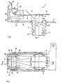
- the generally designated 1 in Figure 1 and there in a closed position pressure regulator is mounted according to a preferred embodiment of a not shown for scale reasons tank installation unit or filter unit of a motor vehicle and is used to control the fuel pressure in the fuel system of a self-igniting internal combustion engine.
- the pressure regulator 1 has an open regulator housing 2 with an L-shaped cross-section, on which a cover, not shown for reasons of clarity, is mounted, in which a pressure outlet 4 indicated only by an arrow is formed, which connects an interior 6 of the regulator housing 2 to the fuel tank. Bodener protrudes into an opening 7 of the controller housing 2, a pressure input 8 forming connector 10 which is connected to a not shown pressure line of the fuel system.
- the controller housing 2 is preferably a one-piece stamped and bent part, in which the connector 10 is inserted. Alternatively, the controller housing 2 could also be made as an injection molded part.
- a valve seat 12 with a conical surface for centering a valve ball 18 is arranged on one end.
- the cone angle of the conical surface is, for example, 60 degrees.
- the valve ball 18 is urged due to the action of a valve leaf spring 16.
- the valve leaf spring 16, the valve ball 18 and the valve seat 12 together form an overflow valve 20 of the pressure regulator 1.
- the valve ball 18 may be made of steel, ceramic or plastic, their diameter is preferably 3 mm to 12 mm.
- the connecting piece 10 which essentially forms a cylindrical bush, has a connecting surface 11 for a line or the like.
- the valve leaf spring 16 preferably has an angular shape consisting of two substantially mutually perpendicular arms 22, 24 and is pivotable about a hinge axis mounted in the controller housing 2 in the form of a pin 26 which is arranged transversely to the longitudinal extent of the valve leaf spring 16 and perpendicular to a plane containing the central axis 28 of the valve seat 12 level.
- the pin 26 engages over the valve leaf spring 16 and extends approximately in the region of the angulation of the valve leaf spring 16, ie in the region of an imaginary joint line of the two arms 22, 24 of the valve leaf spring 16.
- the total length of the wound valve leaf spring for example 10 to 40 mm, their width about 5 mm to 20 mm.
- the distance of the central axis 28 of the valve seat 12 from the pin 26 is preferably 8 mm to 35 mm.
- a damping ring 27 is arranged between the valve seat side arm 22 of the valve leaf spring 16, which is preferably perpendicular to the central axis 28 of the valve seat 12, and the valve leaf spring 16 contacting with its apex valve ball 18, a damping ring 27 is arranged. More specifically, the valve ball 18 protrudes with a spherical segment of their valve leaf spring 16 facing ball half in an annular opening of the damping ring 27 and thereby holds him on the valve leaf spring 16.
- the damping ring 27 preferably has a circular cross section and consists of a plastic.
- the damping ring 27 may be formed by a plastic molding produced by machining or by injection molding, the inner edge facing the valve ball 18 is provided with a chamfer, for example, or has a spherical-layer-shaped seat surface formed complementary to the valve ball 18.
- the damping ring 27 may be made of a different material, for example, made of steel or of an elastomer instead of plastic. It is crucial that form in operation between the damping ring 27, the valve leaf spring 16 and the valve ball 18 frictional forces, which on the one hand are sufficiently large to dampen vibration movements of the valve ball 18, but on the other hand are not so large that the centering of the Valve ball 18 is hindered in the valve seat 12 when the spill valve 20 closes.
- the transverse wall 30 is bent, for example, end to the valve leaf spring 16 and engages in a likewise end, groove-like and transverse fold 32 of the arm 24 of the valve leaf spring 16 a. Since the controller housing 2 is a one-piece component, and the transverse wall 30 with the bottom plate 29 is in one piece.
- the side walls 36 instead of an overlap of the side walls 36 through the Lugs 40 of the transverse wall 30 from the outside, the tabs 40, the side walls 36 also contact overlapping from the inside, ie that the tabs 40 are disposed within the side walls 36 and surrounded by these from the outside.
- the side walls of the regulator housing 2 are preferably also formed by two more of the bottom plate 29 cantilevered and bent tabs 36, as best Fig.1 shows. Between a transverse wall 30 facing portion of the tabs 36 and the bottom plate 29 is a horizontal gap 42 is provided to each of these tabs 36 can crank each other so that they form a guide channel 44 for the valve leaf spring 16 ( Figure 2). More specifically, the tabs 36 enclose the valve leaf spring 16 at least in the region of their angulation with little play. The overlapping of the tabs 36, 40 is preferably carried out in the region of the bend of the tabs 36.
- the tabs 36 acting as side walls are also provided with the bores 34 for the pin 26.
- the valve leaf spring 16 is guided directly by the lugs 40 of the transverse wall 30, which then form the guide channel 44 between them. It is also conceivable that the guide channel 44 is formed both by the tabs 40 and the tabs 36 by taking on each side both tabs 30, 40 relative to the longitudinal extent of the guide channel 44 sections, the leadership function.
- transverse forces acting on the transverse wall 30 due to the tension of the valve leaf spring 16 are consequently transmitted via the tabs 40 and by means of the pin 26 to the tabs 36 acting as side walls and from there into the bottom plate 29.
- the transverse forces arising due to the support of the valve leaf spring 16 on the freely projecting transverse wall 30 are transmitted as tensile forces to the straps 36 acting as side walls.
- the pin 26 creates this as a transfer member a positive connection between the tabs 40 of the transverse wall 30 and acting as side walls tabs 36 without the tabs 36, 40 would have to be interconnected beyond.
- connection between the connecting piece 10 and the regulator housing 2 is generally designed such that the position of the connecting piece 10 relative to the valve leaf spring 16 in the direction of the central axis 28 of the valve seat 12 is arbitrarily adjustable and can be fixed in a defined position.
- the connecting piece 10 In order to allow adjustment of the connecting piece 10 in both directions along the central axis 28 of the valve seat 12, it has at least in the region of the opening 7 of the regulator housing 2 has a substantially continuous peripheral surface.
- the connecting piece 10 is pressed into the opening 7 of the regulator housing 2.
- the connecting piece can be materially connected to the regulator housing, for example by welding, gluing or soldering.
- the fitting 10 could be adjustable by means of a thread relative to the regulator housing and fixed in a defined position.
- the opening pressure of the overflow valve 20 must be set. This is accomplished according to a first alternative by changing the position of the fitting 10 in the direction of the central axis 28 of the valve seat 12 until a closing force corresponding to the desired opening pressure of the valve leaf spring 16 results. In this defined position, the connector 10 is then fixed in the opening 7 relative to the controller housing 2, for example, as already mentioned above, by material closure (gluing, soldering, welding, etc.), by friction (press-in etc.) or by positive engagement (thread etc .)
- a second alternative provides, initially to change the position of the connecting piece 10 in the direction of the central axis 28 of the valve seat 12 such that a lying in the region of the valve ball 18 portion of the valve leaf spring 16 vertically is arranged to the central axis 28 of the valve seat 12.
- the connecting piece 10 is in turn fixed in the opening 7 relative to the controller housing 2 as described above.
- the transverse wall 30 is bent so that a closing force corresponding to the defined opening pressure of the valve leaf spring 16 is generated.
- the operation of the pressure regulator 1 is as follows: If the pressure input 8 fuel pressure prevails, which is large enough to produce a relation to the closing force acting on the valve ball 18 greater pressure force, lifts the valve ball 18 from Valve seat 12 and releases a certain passage cross-section, so that fuel can flow into the interior 6 of the regulator housing 2 and from there to the pressure outlet 4. Due to the elastic properties of the valve leaf spring 16, the passage cross section increases with increasing fuel volume, wherein the pressure difference between the pressure input 8 and pressure output, however, increases only slightly and approximately linearly.
- the invention is not limited to such a pressure regulator 1.
- the pressure regulator according to the invention can also be a pressure regulator in which the size of the outlet pressure differs from that of the inlet pressure and can be adjusted.
Landscapes
- Engineering & Computer Science (AREA)
- General Engineering & Computer Science (AREA)
- Mechanical Engineering (AREA)
- Physics & Mathematics (AREA)
- Chemical & Material Sciences (AREA)
- Combustion & Propulsion (AREA)
- Fluid Mechanics (AREA)
- General Physics & Mathematics (AREA)
- Automation & Control Theory (AREA)
- Manufacturing & Machinery (AREA)
- Safety Valves (AREA)
Claims (10)
- Régulateur de pression, en particulier pour un système d'alimentation en carburant d'un moteur à combustion interne, pour réguler une pression de liquide, comprenant une soupape qui présente un obturateur de soupape (18) poussé dans la position de fermeture par l'effet d'un ressort à lame (16) contre un siège de soupape (12) porté par un support de siège, un bras (22) du ressort à lame (16) étant en appui sur l'obturateur (18), l'autre bras (24) étant en appui sur un organe d'appui (30) d'un boîtier de régulateur (2) et le ressort à lame (16) étant logé de façon articulée dans le boîtier de régulateur (2), le support de siège (10) étant relié, en tant que composant séparé, au boîtier de régulateur (2),
caractérisé en ce que
la liaison entre le support de siège (10) et le boîtier de régulateur (2) est conçue pour faire varier à souhait la position du support de siège (10) par rapport au ressort à lame (16) en direction de l'axe (28) du siège de soupape (12) et fixer le support de siège (10) dans une position définie. - Régulateur de pression selon la revendication 1,
caractérisé en ce que
le support de siège de soupape (10) présente une surface périphérique essentiellement sans paliers qui s'engage dans une ouverture (7) du boîtier de régulateur (2). - Régulateur de pression selon la revendication 2,
caractérisé en ce que
le support de siège de soupape (10) est pressé dans l'ouverture (7) du boîtier de régulateur (2). - Régulateur de pression selon la revendication 2,
caractérisé en ce que
le support de siège de soupape (10) est relié au boîtier de régulateur (2) par complémentarité de matières. - Régulateur de pression selon la revendication 2,
caractérisé en ce que
le support de siège de soupape (10) peut être réglé et fixé au moyen d'un filet dans une position définie par rapport au boîtier de régulateur (2). - Régulateur de pression selon au moins l'une des revendications précédentes,
caractérisé en ce que
le support de siège de soupape (10) est formé par une douille essentiellement cylindrique qui présente d'un côté le siège de soupape (12) et de l'autre côté une surface de raccordement (11) pour une alimentation en pression. - Procédé de réglage d'un régulateur de pression, en particulier d'un régulateur de pression pour un système d'alimentation en carburant d'un moteur à combustion interne, pour réguler une pression de liquide, comprenant une soupape qui présente un obturateur de soupape (18) poussé dans la position de fermeture par l'effet d'un ressort à lame (16) contre un siège de soupape (12) porté par un support de siège, un bras (22) du ressort à lame de soupape (16) étant en appui sur l'obturateur (18), l'autre bras (24) étant en appui sur un organe d'appui (30) d'un boîtier de régulateur (2) et le ressort à lame (16) étant logé de façon articulée dans le boîtier de régulateur (2), selon lequel le support (10) est un composant séparé, relié au boîtier de régulateur (2), et la liaison entre le support de siège (10) et le boîtier de régulateur (2) est conçue pour pouvoir varier à souhait la position du support de siège de soupape (10) par rapport au ressort à lame (16) en direction de l'axe (28) du siège de soupape (12), et pour régler le régulateur de pression on déplace la position du support de siège (10) en direction de l'axe (28) du siège de soupape (12) et on fixe le support de siège (10) dans une position définie.
- Procédé de réglage d'un régulateur de pression selon la revendication 7,
caractérisé en ce que
dans une étape de procédé on règle la position du support de siège (10) en direction de l'axe (28) du siège de soupape (12) de sorte qu'un segment du ressort à lame (16) situé dans la zone de l'obturateur (18) se trouve perpendiculaire à l'axe (28) du siège de soupape (12). - Procédé de réglage d'un régulateur de pression selon la revendication 7 ou 8,
caractérisé en ce que
dans une étape de procédé on règle la pression d'ouverture du régulateur de pression (1) en déplaçant le support de siège (10) en direction de l'axe (28) du siège de soupape (12). - Procédé de réglage d'un régulateur de pression selon l'une quelconque des revendications 7 à 9,
caractérisé en ce que
dans une étape de procédé on règle l'organe d'appui (30) pour générer une force de précontrainte du ressort à lame (16) sur l'obturateur de soupape (18) correspondant à une pression d'ouverture définie.
Applications Claiming Priority (2)
| Application Number | Priority Date | Filing Date | Title |
|---|---|---|---|
| DE10322478A DE10322478A1 (de) | 2003-05-19 | 2003-05-19 | Druckregler |
| DE10322478 | 2003-05-19 |
Publications (2)
| Publication Number | Publication Date |
|---|---|
| EP1480098A1 EP1480098A1 (fr) | 2004-11-24 |
| EP1480098B1 true EP1480098B1 (fr) | 2007-03-21 |
Family
ID=33039198
Family Applications (1)
| Application Number | Title | Priority Date | Filing Date |
|---|---|---|---|
| EP04006511A Expired - Lifetime EP1480098B1 (fr) | 2003-05-19 | 2004-03-18 | Regulateur de pression |
Country Status (2)
| Country | Link |
|---|---|
| EP (1) | EP1480098B1 (fr) |
| DE (2) | DE10322478A1 (fr) |
Cited By (1)
| Publication number | Priority date | Publication date | Assignee | Title |
|---|---|---|---|---|
| US11339688B2 (en) | 2020-01-29 | 2022-05-24 | Borgwarner, Inc. | Variable camshaft timing valve assembly |
Families Citing this family (1)
| Publication number | Priority date | Publication date | Assignee | Title |
|---|---|---|---|---|
| CN104373650A (zh) * | 2014-11-18 | 2015-02-25 | 温州仁谦汽车油泵有限公司 | 一种弹片式恒压阀 |
Family Cites Families (1)
| Publication number | Priority date | Publication date | Assignee | Title |
|---|---|---|---|---|
| DE10107223A1 (de) * | 2001-02-16 | 2002-08-22 | Bosch Gmbh Robert | Druckregler |
-
2003
- 2003-05-19 DE DE10322478A patent/DE10322478A1/de not_active Withdrawn
-
2004
- 2004-03-18 DE DE502004003253T patent/DE502004003253D1/de not_active Expired - Lifetime
- 2004-03-18 EP EP04006511A patent/EP1480098B1/fr not_active Expired - Lifetime
Cited By (1)
| Publication number | Priority date | Publication date | Assignee | Title |
|---|---|---|---|---|
| US11339688B2 (en) | 2020-01-29 | 2022-05-24 | Borgwarner, Inc. | Variable camshaft timing valve assembly |
Also Published As
| Publication number | Publication date |
|---|---|
| DE10322478A1 (de) | 2004-12-16 |
| DE502004003253D1 (de) | 2007-05-03 |
| EP1480098A1 (fr) | 2004-11-24 |
Similar Documents
| Publication | Publication Date | Title |
|---|---|---|
| DE69115887T2 (de) | Niederdruckrückschlagventil | |
| DE19649554B4 (de) | Membrandruckregelventilanordnung | |
| EP1927786B1 (fr) | Valve de commande pour systèmes de tension de moyen de traction | |
| EP1490594B1 (fr) | Soupape d'injection de carburant | |
| EP1604106B1 (fr) | Regulateur de pression | |
| DE2511501A1 (de) | Drosselklappenventil | |
| DE4211911A1 (de) | Magnetbetaetigtes druckregelventil | |
| DE102008042089A1 (de) | Überströmventil für die Zuleitung des Zumessventils der Einspritzpumpe einer Verbrennungskraftmaschine | |
| DE19962960A1 (de) | Druckregelventil und Verfahren zum Herstellen eines Druckregelventils | |
| EP1913241A1 (fr) | Soupape de regulation de pression pneumatique | |
| DE102005030957B4 (de) | Einrichtung zur Dämpfung des Ankerhubs in Magnetventilen | |
| EP1664522B1 (fr) | Module de filtration et soupape pour systeme d'alimentation en carburant | |
| DE102019212350A1 (de) | Bremssystemdämpfvorrichtung mit einem Durchlass in einem Trennelement | |
| DE20016214U1 (de) | Drosselventil zur selbsttätigen Regelung des Drucks im Kurbelgehäuse einer Brennkraftmaschine | |
| EP1480098B1 (fr) | Regulateur de pression | |
| DE10204269A1 (de) | Druckregler für eine Kraftstoffversorgungsanlage einer Brennkraftmaschine | |
| DE102009001099A1 (de) | Kraftstoffeinspritzventil | |
| EP1514022B1 (fr) | Regulateur de pression pour systeme d'alimentation en carburant d'un moteur a combustion interne | |
| EP1916411A2 (fr) | Vanne d'un dispositif d'injection de carburant | |
| DE10002715A1 (de) | Kraftstoffeinspritzventil für Brennkraftmaschinen und ein Verfahren zur Herstellung desselben | |
| DE3932269C2 (de) | Druckbegrenzungsventil für einen Hydraulikkreis | |
| DE1960683C3 (de) | Fliehkraftdruckregler, insbesondere für eine Steueranlage von Kraftfahrzeug Wechselgetrieben | |
| EP1370761A1 (fr) | Injecteur | |
| DE2308453B2 (de) | Ventil zur temperaturabhängigen Steuerung eines gasförmigen oder flussigen Mediums | |
| EP1893867A1 (fr) | Corps de chambre d'accumulation haute pression presentant des elements d'etranglement haute pression |
Legal Events
| Date | Code | Title | Description |
|---|---|---|---|
| PUAI | Public reference made under article 153(3) epc to a published international application that has entered the european phase |
Free format text: ORIGINAL CODE: 0009012 |
|
| AK | Designated contracting states |
Kind code of ref document: A1 Designated state(s): AT BE BG CH CY CZ DE DK EE ES FI FR GB GR HU IE IT LI LU MC NL PL PT RO SE SI SK TR |
|
| AX | Request for extension of the european patent |
Extension state: AL LT LV MK |
|
| 17P | Request for examination filed |
Effective date: 20050524 |
|
| AKX | Designation fees paid |
Designated state(s): DE FR GB IT |
|
| GRAP | Despatch of communication of intention to grant a patent |
Free format text: ORIGINAL CODE: EPIDOSNIGR1 |
|
| RIN1 | Information on inventor provided before grant (corrected) |
Inventor name: PEETZ, ANDREAS Inventor name: MORA, SVATOPLUK Inventor name: HAARER, WERNER Inventor name: FEES, HANS-JOERG Inventor name: ITTLINGER, RALPH Inventor name: RYGL, JAROSLAV |
|
| GRAS | Grant fee paid |
Free format text: ORIGINAL CODE: EPIDOSNIGR3 |
|
| GRAA | (expected) grant |
Free format text: ORIGINAL CODE: 0009210 |
|
| AK | Designated contracting states |
Kind code of ref document: B1 Designated state(s): DE FR GB IT |
|
| REG | Reference to a national code |
Ref country code: GB Ref legal event code: FG4D Free format text: NOT ENGLISH |
|
| REF | Corresponds to: |
Ref document number: 502004003253 Country of ref document: DE Date of ref document: 20070503 Kind code of ref document: P |
|
| GBT | Gb: translation of ep patent filed (gb section 77(6)(a)/1977) |
Effective date: 20070620 |
|
| ET | Fr: translation filed | ||
| PLBE | No opposition filed within time limit |
Free format text: ORIGINAL CODE: 0009261 |
|
| STAA | Information on the status of an ep patent application or granted ep patent |
Free format text: STATUS: NO OPPOSITION FILED WITHIN TIME LIMIT |
|
| 26N | No opposition filed |
Effective date: 20071227 |
|
| REG | Reference to a national code |
Ref country code: FR Ref legal event code: PLFP Year of fee payment: 13 |
|
| REG | Reference to a national code |
Ref country code: FR Ref legal event code: PLFP Year of fee payment: 14 |
|
| REG | Reference to a national code |
Ref country code: FR Ref legal event code: PLFP Year of fee payment: 15 |
|
| PGFP | Annual fee paid to national office [announced via postgrant information from national office to epo] |
Ref country code: GB Payment date: 20180326 Year of fee payment: 15 |
|
| PGFP | Annual fee paid to national office [announced via postgrant information from national office to epo] |
Ref country code: IT Payment date: 20180322 Year of fee payment: 15 Ref country code: FR Payment date: 20180326 Year of fee payment: 15 |
|
| GBPC | Gb: european patent ceased through non-payment of renewal fee |
Effective date: 20190318 |
|
| PG25 | Lapsed in a contracting state [announced via postgrant information from national office to epo] |
Ref country code: GB Free format text: LAPSE BECAUSE OF NON-PAYMENT OF DUE FEES Effective date: 20190318 |
|
| PG25 | Lapsed in a contracting state [announced via postgrant information from national office to epo] |
Ref country code: FR Free format text: LAPSE BECAUSE OF NON-PAYMENT OF DUE FEES Effective date: 20190331 Ref country code: IT Free format text: LAPSE BECAUSE OF NON-PAYMENT OF DUE FEES Effective date: 20190318 |
|
| PGFP | Annual fee paid to national office [announced via postgrant information from national office to epo] |
Ref country code: DE Payment date: 20200526 Year of fee payment: 17 |
|
| REG | Reference to a national code |
Ref country code: DE Ref legal event code: R119 Ref document number: 502004003253 Country of ref document: DE |
|
| PG25 | Lapsed in a contracting state [announced via postgrant information from national office to epo] |
Ref country code: DE Free format text: LAPSE BECAUSE OF NON-PAYMENT OF DUE FEES Effective date: 20211001 |