EP1480023B1 - Appareil de mesure avec dispositif pour l'identification d'un capteur ultrasonore connecté - Google Patents
Appareil de mesure avec dispositif pour l'identification d'un capteur ultrasonore connecté Download PDFInfo
- Publication number
- EP1480023B1 EP1480023B1 EP04011707A EP04011707A EP1480023B1 EP 1480023 B1 EP1480023 B1 EP 1480023B1 EP 04011707 A EP04011707 A EP 04011707A EP 04011707 A EP04011707 A EP 04011707A EP 1480023 B1 EP1480023 B1 EP 1480023B1
- Authority
- EP
- European Patent Office
- Prior art keywords
- ultrasonic sensor
- sensor
- oscillation
- amplitude
- ultrasonic
- Prior art date
- Legal status (The legal status is an assumption and is not a legal conclusion. Google has not performed a legal analysis and makes no representation as to the accuracy of the status listed.)
- Expired - Fee Related
Links
Images


Classifications
-
- G—PHYSICS
- G01—MEASURING; TESTING
- G01F—MEASURING VOLUME, VOLUME FLOW, MASS FLOW OR LIQUID LEVEL; METERING BY VOLUME
- G01F23/00—Indicating or measuring liquid level or level of fluent solid material, e.g. indicating in terms of volume or indicating by means of an alarm
- G01F23/22—Indicating or measuring liquid level or level of fluent solid material, e.g. indicating in terms of volume or indicating by means of an alarm by measuring physical variables, other than linear dimensions, pressure or weight, dependent on the level to be measured, e.g. by difference of heat transfer of steam or water
- G01F23/28—Indicating or measuring liquid level or level of fluent solid material, e.g. indicating in terms of volume or indicating by means of an alarm by measuring physical variables, other than linear dimensions, pressure or weight, dependent on the level to be measured, e.g. by difference of heat transfer of steam or water by measuring the variations of parameters of electromagnetic or acoustic waves applied directly to the liquid or fluent solid material
- G01F23/296—Acoustic waves
- G01F23/2968—Transducers specially adapted for acoustic level indicators
-
- G—PHYSICS
- G01—MEASURING; TESTING
- G01F—MEASURING VOLUME, VOLUME FLOW, MASS FLOW OR LIQUID LEVEL; METERING BY VOLUME
- G01F25/00—Testing or calibration of apparatus for measuring volume, volume flow or liquid level or for metering by volume
- G01F25/20—Testing or calibration of apparatus for measuring volume, volume flow or liquid level or for metering by volume of apparatus for measuring liquid level
- G01F25/24—Testing proper functioning of electronic circuits
-
- G—PHYSICS
- G01—MEASURING; TESTING
- G01N—INVESTIGATING OR ANALYSING MATERIALS BY DETERMINING THEIR CHEMICAL OR PHYSICAL PROPERTIES
- G01N2291/00—Indexing codes associated with group G01N29/00
- G01N2291/02—Indexing codes associated with the analysed material
- G01N2291/028—Material parameters
- G01N2291/02836—Flow rate, liquid level
Definitions
- the invention relates to a level measuring device with a meter electronics, to the ultrasonic sensors with different resonant frequencies can be connected.
- Ultrasonic sensors are used in a variety of applications. Ultrasonic sensors are used e.g. used as transmitter and / or receiver in level measuring devices for distance measurement according to the echosounding principle.
- fill level measuring devices it is possible, inter alia, to fill levels of a product, e.g. in a container or in an open channel.
- a signal emitted by the ultrasonic sensor e.g. a short ultrasonic wave pulse, sent in the direction of the contents and reflected on the surface of the contents.
- the duration of the pulse from the sensor to the surface and back is determined and from this the fill level or fill level is determined.
- Such meters are used in many industries, e.g. used in the food industry, the water and wastewater sector and in chemistry.
- ultrasonic sensors with different resonance frequencies are used.
- the resonance frequencies are in a range of 1 kHz to 200 kHz.
- Measuring instruments therefore advantageously have a meter electronics, to which various ultrasonic sensors can be connected.
- the meter Before the meter can be put into operation, it must be determined which ultrasonic sensor is connected. This is preferably done automatically by the meter is equipped with a device for detecting the connected ultrasonic sensor, which performs this task.
- ultrasonic sensors are therefore used e.g. equipped with a label resistor.
- the identification resistor is connected to a resistance measuring circuit which detects the connected ultrasonic sensor based on the resistance value of the identification resistor.
- ultrasonic sensors without identification resistor can not be detected.
- a vibration level limit switch has become known, which uses a piezoelectric element as the output element.
- the level limit switch is designed to allow the testing of its essential components through the use of a reference bandpass filter and the tamper-proof transmission of test and measurement values.
- the test command is formed by the amplitude control of the current flowing between the limit switch and a remotely located evaluation device on a two-wire line to a value lying outside the Meßstrom Suites. The value is preferably above the power consumption of the limit switch.
- the signals will be rectified and an integral is calculated over the rectified signals or one of the rectified signals envelope.
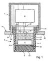
- Fig. 1 shows a longitudinal section through a measuring device according to the invention. It comprises a meter housing 1, in which a meter electronics 3 is arranged.
- the meter housing 1 is made of metal, for example of a stainless steel.
- the ultrasonic sensor 5 has a pot-shaped housing 7, which is closed off by a bottom 9.
- the housing 7 is made of a plastic, such as polypropylene.
- a piezoelectric element 11 is arranged, which serves to generate and / or recording of ultrasound through the bottom 9 therethrough.
- a matching layer 13 is disposed in front of the piezoelectric element 11 of a plastic having a mean acoustic impedance.
- plastic e.g. an epoxy resin suitable.
- the piezoelectric element 11 is disc-shaped.
- the matching layer 13 is also disk-shaped and is located between the piezoelectric element 11 and the bottom 9 of the housing 7.
- the matching layer 13 preferably has a thickness which corresponds to one quarter of the wavelength of the generated sound or ultrasound waves.
- a damping material 15 is therefore preferably provided in the housing 7.
- the damping material 15 is, for example, a casting, for example a silicone gel, which fills the housing 7.
- the meter is modular.
- the ultrasonic sensor 5 is enclosed in a holder 17.
- the holder 17 has a cylindrical portion, on the end a radially inwardly extending shoulder 19 is formed.
- the housing 7 has at its end facing away from the bottom 9 a radially outwardly extending shoulder 21 which rests on the shoulder 19.
- the pressure ring 23 rests on the shoulder 21 and thus fixes the housing 7 in the holder 17.
- the measuring device housing 1 is externally screwed onto the cylindrical portion of the holder 17.
- a radially outwardly extending flange 25 is formed on the holder 17, with which the meter is mounted on a site.
- other modular designs are possible.
- the meter electronics 3 is connected via a connection 27 to the ultrasonic sensor 5.
- a disk-shaped connection electrode 29 is provided on the piezoelectric element 11 on the measuring device electronics-facing end face, to which a line 31 is connected, which leads to a connector 33 arranged at the open end of the housing 7.
- the connection 27 leads from the meter electronics 3 to the connector 33rd
- connection 27 While in conventional measuring instruments with characteristic resistors in addition to the characteristic impedance leading connection lines are required in the inventive meter, the connection 27 between the meter electronics 3 and the ultrasonic sensor 5. About this connection 27 is carried out both the detection of the connected ultrasonic sensor 5 and the terminal of the ultrasonic sensor. 5 in measuring mode.
- a further electrode 35 is provided, to which a Connecting line 37 is connected. Via the connecting line 37, the electrode 35 is connected to ground or to a fixed reference potential.
- the meter electronics 3 is used to control the ultrasonic sensor 5.
- the meter electronics 3 can be used both when sending and when receiving ultrasonic signals.
- a connected ultrasonic sensor 5 is exchangeable simply by being mechanically released from the meter housing 1 and replaced by another ultrasonic sensor 5.
- ultrasonic sensors 5 can be connected to the measuring device electronics 3.
- the connectable ultrasonic sensors 5 differ in sensor-specific sizes, e.g. their resonance frequency.
- a device for detecting the connected ultrasonic sensor 5 which oscillates the ultrasound sensor 5 to detect the ultrasonic sensor 5, absorbs its oscillatory behavior and derives therefrom a sensor-specific variable.
- Fig. 2 shows an embodiment of a circuit diagram of a connection 27 connected to the ultrasonic sensor 5 Meßellolektronik 3. It includes a digital signal processor 39.
- the digital signal processor 39 is connected via a digital-to-analog converter 41 and the connecting line 27 to the ultrasonic sensor 5.
- the digital signal processor 39 can generate digital signals via the digital-to-analog converter 41 are converted into analog signals and abut in analog form on the ultrasound sensor 5.
- the analog signals cause the piezoelectric element 11 to vibrate.
- the vibration behavior of the ultrasonic sensor 5 is supplied in the illustrated circuit via the connection 27 to a connected analog-to-digital converter 43, which digitizes the incoming signals and the digital signal processor 39 supplies.
- ultrasound signals as are commonly used in ultrasound measuring technology today, are transmitted and / or received in the range from 1 kHz to 200 kHz, commercially available analog-to-digital converters and digital / analog converters with sampling rates of about 1 MHz can be used.
- digital signal processors with clock rates of a few gigahertz are commercially available, which operate sufficiently fast to be able to provide not only the signals for exciting the ultrasonic sensor 5, but also to be able to directly record and process the vibration behavior of the ultrasonic sensor 5.
- a short ultrasonic wave pulse is generated, for example, in the manner described above, which is sent by the ultrasonic sensor 5 in the direction of the filling material. It is received after a level-dependent runtime whose echo signal and evaluated by means of the digital signal processor 39.
- the device for detecting the connected ultrasonic sensor is preferably integrated in the digital signal processor 39.
- a program may be provided, which is run through when switching on the meter before the first measurement.
- the program serves to carry out a method for detecting the ultrasonic sensor 5 connected to the measuring device.
- Various methods are possible, which set the ultrasonic sensor in vibration, absorb its vibration behavior and derive a sensor-specific size.
- Ultrasonic sensors are oscillatory damped systems whose vibration characteristics are essentially determined by their quality Q and a natural frequency f 0 of the corresponding undamped system.
- a sensor-specific size of the ultrasound sensor 5 for example an amplitude A of the oscillation which sets itself under predetermined conditions, whose decay time ⁇ , whose natural frequency f 0 or its resonant frequency f res is turned off.
- the ultrasonic sensor is excited to oscillate at a predetermined frequency f and a given amplitude A s .
- the amplitude A (T) of the oscillation of the ultrasonic sensor 5 is recorded after a fixed time T after termination of the excitation.
- This amplitude A (T) is a sensor-specific variable, by means of which the connected ultrasonic sensor 5 can be determined. This is preferably done by recording for all provided different ultrasonic sensors 5 in advance the amplitude A (T) with which these swing after the fixed time T after completion of the above-described excitation with the predetermined frequency f and the predetermined amplitude A s .
- the amplitude A (T) is stored for each ultrasonic sensor in a table in the meter.
- the sensor-specific value of the amplitude A (T) recorded with this ultrasound sensor 5 is subsequently compared with the values stored in the table. From the comparison results directly, which ultrasonic sensor 5 is connected.
- This method is particularly suitable in cases where the decay times of the connectable ultrasonic sensors 5 are about the same.
- the connected ultrasonic sensor 5 Once the connected ultrasonic sensor 5 has been determined, it is excited by the measuring device electronics 3 in a subsequent measuring operation in an optimum form for this ultrasonic sensor 5.
- the ultrasonic sensor 5 is excited to oscillate.
- amplitude A s and frequency f of the excitation need not be fixed.
- a development of the amplitude of the oscillation of the connected ultrasound sensor 5 is recorded over a period of time and a decay time ⁇ is determined from the development.
- the amplitude during decay drops exponentially with the decay time ⁇ .
- This method is particularly suitable if the connectable ultrasonic sensors have similar Q qualities.
- the decay time ⁇ can be determined, for example, by measuring the amplitude A (t1) and A (t2) after completion of the excitation at two different times t1 and t2.
- the decay time ⁇ is a sensor-specific variable, by means of which the connected ultrasonic sensor 5 can be correctly identified.
- a table of the decay times ⁇ of the different connectable ultrasonic sensors 5 is preferably applied beforehand and stored in a memory in the measuring device. The detection of the connected ultrasonic sensor 5 then takes place by the measured Abkingzeit ⁇ is compared with the stored in the table sensor-specific decay times ⁇ .
- the ultrasonic sensor 5 is excited to oscillate at any frequency and amplitude.
- a frequency f d or a period T d of the oscillation recorded by the ultrasonic sensor.
- Frequency f d and period T d are inversely proportional to each other and depend as stated above on the natural frequency f 0 and the Q of the ultrasonic sensor 5 from. Accordingly, they represent sensor-specific variables that are suitable for detecting the connected ultrasonic sensor 5.
- Frequency f d or period T d can be determined, for example, by recording an amplitude curve of the oscillation after completion of the excitation. On the basis of zero crossings and / or the position of minima and maxima of the amplitude curve both quantities can be determined.
- the sensor-specific frequencies f d and / or period lengths T d are preferably determined in advance for all provided ultrasonic sensors 5 and stored in a table. By comparing the measured values with the values stored in the table, the connected ultrasonic sensor 5 can be detected.
- the ultrasonic sensor 5 is excited to oscillate at a predetermined frequency f and a predetermined amplitude A s .
- a measure of a vibration energy of the ultrasonic sensor 5 forms a sensor-specific variable, by means of which the connected ultrasonic sensor 5 can be seen.
- the physical effect is exploited that the more vibrational energy is transmitted to the ultrasonic sensor 5 and emitted by the latter, the closer the predetermined frequency f, with which is excited, is at the resonant frequency f res .
- this measure of the vibration energy is determined by the signals of the ultrasonic sensor 5 during the predetermined period to be rectified. This gives a signal amplitude as a function of time. An integral over the thus determined signal amplitude over the given period gives a measure of the vibration energy.
- an envelope may be determined for the rectified signals and the integral calculated across the envelope.
- the measure of the vibration energy is determined in advance for all usable different ultrasonic sensors 5 and stored in the meter. A simple comparison of the measured value with the previously stored values then results in a clear identification of the connected ultrasonic sensor.
- the entire signal excitation and signal processing is performed in digital form. But it is also possible to equip measuring instruments according to the invention with a largely analog signal excitation and signal processing.
- FIG. 3 shows a circuit diagram of a meter electronics 3 with a transmission signal generation 45 and a receiving circuit 47, as it is also used in conventional measuring instruments.
- the transmission signal generation 45 generates, for example, short pulses with the resonant frequency f res of the respectively connected ultrasound sensor 5.
- the signals generated are applied to the ultrasound sensor 5 via the connection line 27. Accordingly, signals received by the ultrasonic sensor 5 are supplied via the connecting line 27 to the receiving circuit 47.
- the receiving circuit 47 has an amplifier 49 and a logarithmizer 51 connected downstream of it.
- the signals stretched by the logarithmization are provided to an analog-digital converter 53 and from this to a microprocessor 55 for evaluation and / or processing. Due to the analog preprocessing of the incoming signals an analog-to-digital converter with a sampling rate of less than 100 kHz is sufficient.
- the measuring device comprises a device for detecting the connected ultrasound sensor, which oscillates the ultrasound sensor 5 in order to detect the ultrasound sensor 5, records its oscillatory behavior and derives therefrom a sensor-specific variable.
- This device comprises a device by which the connected ultrasonic sensor 5 can be excited to oscillate.
- this device is the transmission signal generation 45, which is in any case connected to the ultrasonic sensor 5.
- the device comprises for each ultrasonic sensor 5, which it can recognize, an associated test branch T1... TN, to which signals recorded by the respectively connected ultrasonic sensor 5 can be applied.
- a switch 57 is provided, via which the signals received by the ultrasonic sensor 5 are selectively supplied to the receiving circuit 47 or to a feed line 59 to the test branches T1... TN.
- each test branch T1... TN has a bandpass filter 61 which is permeable to the resonant frequency f res of the assigned ultrasonic sensor 5.
- Each test branch T1... TN has a recording unit which receives signals passing through the bandpass filter 61.
- the recording unit comprises analog-to-digital converters 63 which are connected downstream of the bandpass filters 61.
- the analog-to-digital converters 63 feed the signals supplied to them in digitized form into a microprocessor 65, which is also part of the recording unit.
- the miroprocessors 55 and 65 are two separate components, but it is also possible instead to provide only a single microprocessor which replaces the two microprocessors 55 and 65.
- the ultrasonic sensor 5 If the ultrasonic sensor 5 is excited to vibrate with a signal having a broad frequency spectrum, then it will absorb most of the vibration energy in the region of its resonant frequency f res and subsequently emit it again during decoupling in this frequency range as well. Accordingly, in the test branch T in which the resonance frequency f res of the currently connected ultrasound sensor 5 is filtered out, the greatest signal power is present.
- This test branch T is determined by means of the microprocessor 65. In this case, for example, that test branch T having the largest signal amplitude can be determined. Likewise, for each test branch T, the signal amplitude can be integrated over a predetermined period of time. If the test branch T is known, the connected ultrasonic sensor 5 is also detected.
- the meter automatically detects which ultrasonic sensor 5 is connected. Preferably, the detection of the connected ultrasonic sensor 5 is automatically carried out after each turn on the meter. If the ultrasonic sensor 5 is detected, it is preferably excited in the measuring mode for transmitting with its resonant frequency fres, since at this frequency a high transmission power can be achieved and power losses are low.
Claims (9)
- Appareil de mesure destiné à la détermination du niveau d'un produit au sein d'un réservoir ou dans un caniveau ouvert à l'aide d'un capteur à ultrasons (5) et d'une électronique d'appareil de mesure (3), le capteur à ultrasons (5) émettant un signal ultrasonore en direction du produit et recevant le signal ultrasonore réfléchi à la surface du produit, et l'électronique d'appareil de terrain (3) déterminant le niveau à partir du temps de propagation - dépendant du niveau - du signal ultrasonore allant du capteur à ultrasons (5) vers la surface du produit et réfléchi par la surface du produit vers le capteur à ultrasons, différents capteurs à ultrasons (5), qui présentent différentes grandeurs spécifiques aux capteurs, pouvant être raccordés à l'électronique d'appareil de terrain (3) par l'intermédiaire d'une liaison (27), un dispositif d'identification étant prévu pour l'identification des capteurs à ultrasons (5) raccordés, lequel excite le convertisseur à ultrasons (5) en vibrations, enregistre son comportement en vibrations, déduit une grandeur spécifique au capteur sur la base du comportement en vibrations, la grandeur spécifique au capteur s'agissant de l'amplitude (A), du temps de décroissance (T), de la fréquence fondamentale (fo), de la fréquence de résonance (fres), de la fréquence mesurée (fd) au terme de l'excitation, de la durée de période (Td), de la qualité (Q) ou de l'énergie des vibrations du capteur à ultrasons (5), et le dispositif identifiant chaque capteur à ultrasons (5) raccordé sur la base d'une comparaison de la grandeur spécifique au capteur - déduite - avec une grandeur spécifique au capteur - enregistrée - correspondante.
- Appareil de mesure de niveau selon la revendication 1, pour lequel il existe une liaison (27) entre le capteur à ultrasons (5) et l'électronique d'appareil de mesure (3), par l'intermédiaire de laquelle le capteur à ultrasons (5) est raccordé en mode mesure.
- Procédé destiné à l'identification d'un capteur à ultrasons (5) raccordé à l'appareil de mesure de niveau selon l'une des revendications 1 ou 2, pour lequel- le capteur à ultrasons (5) est excité en vibrations avec une fréquence (f) prédéfinie et une amplitude (As) prédéfinie,- une grandeur spécifique au capteur est enregistrée après un temps fixe (T) au terme de l'excitation, la grandeur spécifique au capteur s'agissant de l'amplitude (A), du temps de décroissance (T), de la fréquence fondamentale (fo), de la fréquence de résonance (tries), de la fréquence mesurée (fd) au terme de l'excitation, de la durée de période (Td), de la qualité (Q) ou de l'énergie des vibrations du capteur à ultrasons (5), et- pour lequel est déterminé le capteur à ultrasons au moyen de la grandeur spécifique au capteur, en ce que la grandeur spécifique au capteur est comparée avec une grandeur spécifique au capteur enregistrée dans une table.
- Procédé selon la revendication 3, pour lequel- après un temps fixe (T) au terme de l'excitation, l'amplitude (A(T)) de la vibration est enregistrée en tant que grandeur spécifique au capteur à ultrasons (5) et- le capteur à ultrasons (5) est déterminé au moyen de l'amplitude (A(T)), en ce que l'amplitude (A(T)) est comparée à une amplitude spécifique au capteur enregistrée dans une table.
- Procédé selon la revendication 3, pour lequel- est enregistré, au terme de l'excitation, un développement de l'amplitude (A) de la vibration du capteur à ultrasons (5),- est déterminé à partir de l'amplitude (A) un temps de décroissance (T), avec lequel l'amplitude (A) décroît de manière exponentielle en tant que grandeur spécifique au capteur, et- est déterminé le capteur à ultrasons (5) au moyen du temps de décroissance (T), en ce que le temps de décroissance (T) est comparé à des temps de décroissance (T) enregistrés dans une table.
- Procédé selon la revendication 3, pour lequel- est enregistrée, au terme de l'excitation, une fréquence (fd) ou une durée de période (Td) de la vibration du capteur à ultrasons (5).
- Procédé selon la revendication 3, pour lequel- le capteur à ultrasons (5) est excité en vibrations avec une fréquence (f) prédéfinie et une amplitude (As) prédéfinie,- sont enregistrés, au terme de l'excitation, les signaux du capteur à ultrasons (5) pendant une période de temps déterminée, et- une grandeur décrivant l'énergie de vibration du capteur à ultrasons (5) est déduite pendant cette période de temps,- au moyen de laquelle le capteur à ultrasons (5) est identifié.
- Procédé selon la revendication 7, pour lequel- les signaux sont redressés, et- une intégrale est calculée par le biais des signaux redressés ou d'une enveloppante des signaux redressés.
- Appareil de mesure de niveau selon la revendication 1, pour lequel- le dispositif comprend un système, qui peut être excité en vibrations par le capteur à ultrasons (5) raccordé,- le dispositif, pour chaque capteur à ultrasons (5) qu'il est capable d'identifier, présente une branche de test (T1 ... TN) correspondante, sur laquelle est présent le signal enregistré pour chaque capteur à ultrasons (5) raccordé,- chaque branche de test (T1 ... TN) comporte un filtre passe-bande (61), qui laisse passer la fréquence de résonance (fres) du capteur à ultrasons (5) correspondant, et- chaque branche de test (T1 ... TN) comporte une unité d'enregistrement, qui enregistre les signaux traversant la branche.
Applications Claiming Priority (2)
| Application Number | Priority Date | Filing Date | Title |
|---|---|---|---|
| DE10323062 | 2003-05-20 | ||
| DE10323062A DE10323062A1 (de) | 2003-05-20 | 2003-05-20 | Meßgerät |
Publications (2)
| Publication Number | Publication Date |
|---|---|
| EP1480023A1 EP1480023A1 (fr) | 2004-11-24 |
| EP1480023B1 true EP1480023B1 (fr) | 2010-07-07 |
Family
ID=33039256
Family Applications (1)
| Application Number | Title | Priority Date | Filing Date |
|---|---|---|---|
| EP04011707A Expired - Fee Related EP1480023B1 (fr) | 2003-05-20 | 2004-05-18 | Appareil de mesure avec dispositif pour l'identification d'un capteur ultrasonore connecté |
Country Status (3)
| Country | Link |
|---|---|
| US (1) | US7255006B2 (fr) |
| EP (1) | EP1480023B1 (fr) |
| DE (2) | DE10323062A1 (fr) |
Families Citing this family (17)
| Publication number | Priority date | Publication date | Assignee | Title |
|---|---|---|---|---|
| US7869850B2 (en) | 2005-09-29 | 2011-01-11 | Nellcor Puritan Bennett Llc | Medical sensor for reducing motion artifacts and technique for using the same |
| JP2007183185A (ja) * | 2006-01-06 | 2007-07-19 | Denso Corp | 超音波センサ |
| US8073518B2 (en) | 2006-05-02 | 2011-12-06 | Nellcor Puritan Bennett Llc | Clip-style medical sensor and technique for using the same |
| US8145288B2 (en) | 2006-08-22 | 2012-03-27 | Nellcor Puritan Bennett Llc | Medical sensor for reducing signal artifacts and technique for using the same |
| US7894869B2 (en) | 2007-03-09 | 2011-02-22 | Nellcor Puritan Bennett Llc | Multiple configuration medical sensor and technique for using the same |
| DE102011076224B4 (de) * | 2011-05-20 | 2021-09-30 | Ge Sensing & Inspection Technologies Gmbh | Ultraschallprüfkopf, sowie Ultraschallprüfeinrichtung |
| DE102013113368A1 (de) * | 2013-12-03 | 2015-06-03 | Endress + Hauser Conducta Gesellschaft für Mess- und Regeltechnik mbH + Co. KG | Verfahren und Testanordnung zum Testen eines Betriebszustandes einer Prozessanlage |
| US10072963B1 (en) * | 2014-07-11 | 2018-09-11 | Nick V. Solokhin | Ultrasonic volume-sensing transducer instrument with concave transceiver element |
| WO2017040208A1 (fr) | 2015-08-28 | 2017-03-09 | Crisi Medical Systems, Inc. | Système de capteur d'écoulement avec absorbeur |
| EP3341045B1 (fr) | 2015-08-28 | 2020-12-30 | Crisi Medical Systems, Inc. | Système de capteur de débit avec ensemble de connexion |
| CA3202041A1 (fr) | 2015-08-28 | 2017-03-09 | Crisi Medical Systems, Inc. | Systeme capteur de flux contenant des contacts a ressort |
| EP3341053B1 (fr) | 2015-08-28 | 2020-01-08 | Crisi Medical Systems, Inc. | Système de capteur de débit comprenant une connexion de transmission |
| DE102015122284A1 (de) * | 2015-12-18 | 2017-06-22 | Endress + Hauser Gmbh + Co. Kg | Elektronikeinheit mit Diagnosefunktion |
| CN116688285A (zh) | 2016-06-17 | 2023-09-05 | 贝克顿·迪金森公司 | 用于润湿流体端口的内部流体路径表面以增进超声信号传输的方法和设备 |
| EP4252797A3 (fr) | 2017-06-19 | 2023-12-13 | Becton, Dickinson and Company | Soupape d'amorçage pour induire un profil de pression et d'écoulement approprié et améliorer la disponibilité d'un capteur |
| JP2021532375A (ja) | 2018-07-06 | 2021-11-25 | ベクトン・ディキンソン・アンド・カンパニーBecton, Dickinson And Company | 流量センサおよび流体流測定を調整するための方法 |
| CA3164139A1 (fr) | 2020-01-22 | 2021-07-29 | Kaushal Verma | Appareil et procede pour joindre un coupleur et un canal de circulation dans un debitmetre a ultrasons |
Family Cites Families (28)
| Publication number | Priority date | Publication date | Assignee | Title |
|---|---|---|---|---|
| US4025788A (en) * | 1973-01-18 | 1977-05-24 | Tohoku Electric Power Company, Inc. | Radiometric analyzer |
| US3794236A (en) * | 1973-05-07 | 1974-02-26 | Raytheon Co | Monitoring and control means for evaluating the performance of vibratory-type devices |
| US4049966A (en) * | 1976-07-02 | 1977-09-20 | Beckman Instruments, Inc. | Nuclear radiation measuring method and apparatus having blanking time inversely related to count rate |
| US4271371A (en) * | 1979-09-26 | 1981-06-02 | Kabushiki Kaisha Morita Seisakusho | Driving system for an ultrasonic piezoelectric transducer |
| AT369549B (de) * | 1981-02-10 | 1983-01-10 | List Hans | Pruefeinrichtung zur bestimmung von schwingungseigenschaften |
| JP2663591B2 (ja) * | 1988-12-12 | 1997-10-15 | 日本電気株式会社 | 回転部の接続構造 |
| US5166573A (en) * | 1989-09-26 | 1992-11-24 | Atochem North America, Inc. | Ultrasonic contact transducer and array |
| ES2077595T3 (es) * | 1990-03-16 | 1995-12-01 | Siemens Ag | Cabeza de verificacion ultrasonica y procedimiento para su funcionamiento. |
| US5109227A (en) * | 1990-08-31 | 1992-04-28 | Godfrey Wesley L | Apparatus for identifying and tracking a targeted nuclear source |
| US5329821A (en) * | 1992-05-08 | 1994-07-19 | Nusonics, Inc. | Autoranging sonic flowmeter |
| DE4232719C2 (de) | 1992-09-30 | 1996-05-09 | Grieshaber Vega Kg | Füllstand-Grenzschalter |
| DE4233185C1 (de) * | 1992-10-02 | 1994-01-27 | Endress Hauser Gmbh Co | Vorrichtung zur Feststellung und/oder Überwachung eines vorbestimmten Füllstandes |
| IL108470A (en) * | 1994-01-28 | 1998-12-06 | Mizur Technology Ltd | Passive sensor system using ultrasonic energy |
| DE19538680C2 (de) * | 1995-10-17 | 1998-10-08 | Endress Hauser Gmbh Co | Anordnung zur Überwachung eines vorbestimmten Füllstands einer Flüssigkeit in einem Behälter |
| JP3668860B2 (ja) * | 1996-07-23 | 2005-07-06 | 泰 石井 | 音響式体積計 |
| EP0875741B1 (fr) * | 1997-04-30 | 2008-08-20 | Endress + Hauser GmbH + Co. KG | Dispositif pour la détermination et/ou la surveillance d'un niveau prédéterminé dans un réservoir |
| US6138507A (en) * | 1997-04-30 | 2000-10-31 | Endress + Hauser Gmbh + Co. | Apparatus for establishing and/or monitoring a predetermined filling level in a container through controlled transducer phase and impedance |
| US6141625A (en) * | 1997-06-09 | 2000-10-31 | Dickey-John Corporation | Viscometer module with crystal resonator-type sensor |
| GB2337118A (en) * | 1998-05-06 | 1999-11-10 | Csi Technology Inc | Interchangeable sensor monitoring device |
| DE59907919D1 (de) * | 1998-08-03 | 2004-01-15 | Siemens Ag | Verfahren zum Sendefrequenzabgleich eines Ultraschall-Nährungsschalters und Ultraschall-Nährungsschalter mit Sendefrequenzabgleich |
| CA2276693A1 (fr) * | 1999-06-28 | 2000-12-28 | Frederic Laville | Systeme d'essai de vibration et methode faisant intervenir des ondes acoustiques |
| US6536553B1 (en) * | 2000-04-25 | 2003-03-25 | The United States Of America As Represented By The Secretary Of The Army | Method and apparatus using acoustic sensor for sub-surface object detection and visualization |
| DE10043629A1 (de) * | 2000-09-01 | 2002-03-14 | Endress Hauser Gmbh Co | Vorrichtung zur Bestimmung und/oder Überwachung der Dichte und/oder des Füllstands eines Füllguts in einem Behälter |
| DE10104165A1 (de) * | 2001-01-30 | 2002-09-26 | Endress & Hauser Gmbh & Co Kg | Verfahren zur Bestimmung und Darstellung einer optimirten Anordnung und Montage eines radiomatrischen Mesystem |
| US6531884B1 (en) * | 2001-08-27 | 2003-03-11 | Rosemount Inc. | Diagnostics for piezoelectric sensor |
| DE10162703A1 (de) * | 2001-12-19 | 2003-07-03 | Endress & Hauser Gmbh & Co Kg | Verfahren und Vorrichtung zur Fehlerausblendung und -Kompensation von durch Gammagraphie hervorgerufenen Störsignalen bei radiometrischen Meßsystemen |
| US6923063B2 (en) * | 2002-09-16 | 2005-08-02 | Radiaulics, Inc. | Acoustic sensing device, system and method for monitoring emissions from machinery |
| EP1406005B1 (fr) * | 2002-09-20 | 2006-04-19 | Ford Global Technologies, Inc. | Méthode et appareil de surveillance de valves de commande |
-
2003
- 2003-05-20 DE DE10323062A patent/DE10323062A1/de not_active Withdrawn
-
2004
- 2004-05-18 DE DE502004011356T patent/DE502004011356D1/de active Active
- 2004-05-18 EP EP04011707A patent/EP1480023B1/fr not_active Expired - Fee Related
- 2004-05-20 US US10/849,128 patent/US7255006B2/en active Active
Also Published As
| Publication number | Publication date |
|---|---|
| EP1480023A1 (fr) | 2004-11-24 |
| US20050039533A1 (en) | 2005-02-24 |
| DE502004011356D1 (de) | 2010-08-19 |
| US7255006B2 (en) | 2007-08-14 |
| DE10323062A1 (de) | 2004-12-09 |
Similar Documents
| Publication | Publication Date | Title |
|---|---|---|
| EP1480023B1 (fr) | Appareil de mesure avec dispositif pour l'identification d'un capteur ultrasonore connecté | |
| EP1480021B1 (fr) | Procédé de mesure du niveau d' un fluide | |
| DE4311963C2 (de) | Füllstandsmeßgerät | |
| DE4025326C2 (de) | Verfahren und Vorrichtung zum Messen der Flüssigkeitshöhe einer bewegten Flüssigkeit in einem Behälter | |
| DE102005038649B4 (de) | Verfahren und System zum Betreiben eines Ultraschallwandlers | |
| DE102017120682A1 (de) | Vorrichtung und verfahren zum betreiben eines ultraschallsensors | |
| DE3812293A1 (de) | Fuellstandsmessgeraet | |
| DE112010000828T5 (de) | Luftblasendetektor | |
| DE102009045204A1 (de) | Verfahren zur Bestimmung und/oder Überwachung mindestens einer physikalischen Prozessgröße | |
| DE10360711A1 (de) | Füllstandsmeßgerät und Verfahren zur Füllstandsmessung und -überwachung | |
| WO2012123344A1 (fr) | Procédé d'étalonnage d'un capteur de niveau à ultrasons | |
| EP1573276B1 (fr) | Dispositif de positionnement d'un appareil de mesure de debit sous forme de pince de serrage sur un contenant | |
| EP1800093B1 (fr) | Dispositif pour determiner et/ou controler une grandeur de processus d'un milieu | |
| WO2003002952A1 (fr) | Dispositif de determination et/ou de surveillance de l'etat de remplissage d'un recipient avec une substance | |
| EP3314210A1 (fr) | Appareil émetteur de champs doté d'un circuit de compensation pour l'élimination des impacts environnementaux | |
| EP0742372A1 (fr) | Système de surveillance pour détecter l'intensité de la cavitation | |
| EP1743142B1 (fr) | Dispositif de mesure ultrasonique pour determiner et/ou surveiller le debit volumique et/ou massique d'une substance | |
| EP3517946B1 (fr) | Procédé de détermination d'une valeur corrigée de la vitesse sonique dépendant de la viscosité dans un fluide à analyser | |
| DE2059343A1 (de) | Anordnung zur UEberwachung der Resonanzfrequenz eines Koerpers | |
| DE4437684C2 (de) | Vorrichtung zur Messung der Konzentration einer in einem Behältnis befindlichen, sich zeitlich stofflich verändernden Flüssigkeit | |
| EP1985974A2 (fr) | Procédé destiné à la détermination d'une caractéristique d'un milieu s'écoulant | |
| EP0855577A1 (fr) | Procédé pour mettre au point des paramètres autonomy d'un mètre ultrasonore | |
| DE102010003733A1 (de) | Verfahren zur Detektion von Gasblasen in einem flüssigen Medium | |
| EP3812713B1 (fr) | Dispositif de mesure et procédé de fonctionnement d'un dispositif de mesure servant à déterminer une grandeur de fluide | |
| DE102004059050A1 (de) | Vorrichtung zur Bestimmung und/oder Überwachung einer Prozessgröße |
Legal Events
| Date | Code | Title | Description |
|---|---|---|---|
| PUAI | Public reference made under article 153(3) epc to a published international application that has entered the european phase |
Free format text: ORIGINAL CODE: 0009012 |
|
| AK | Designated contracting states |
Kind code of ref document: A1 Designated state(s): AT BE BG CH CY CZ DE DK EE ES FI FR GB GR HU IE IT LI LU MC NL PL PT RO SE SI SK TR |
|
| AX | Request for extension of the european patent |
Extension state: AL HR LT LV MK |
|
| 17P | Request for examination filed |
Effective date: 20050326 |
|
| AKX | Designation fees paid |
Designated state(s): DE FR GB IT |
|
| 17Q | First examination report despatched |
Effective date: 20070315 |
|
| GRAP | Despatch of communication of intention to grant a patent |
Free format text: ORIGINAL CODE: EPIDOSNIGR1 |
|
| GRAS | Grant fee paid |
Free format text: ORIGINAL CODE: EPIDOSNIGR3 |
|
| GRAA | (expected) grant |
Free format text: ORIGINAL CODE: 0009210 |
|
| AK | Designated contracting states |
Kind code of ref document: B1 Designated state(s): DE FR GB IT |
|
| REG | Reference to a national code |
Ref country code: GB Ref legal event code: FG4D |
|
| REF | Corresponds to: |
Ref document number: 502004011356 Country of ref document: DE Date of ref document: 20100819 Kind code of ref document: P |
|
| PLBE | No opposition filed within time limit |
Free format text: ORIGINAL CODE: 0009261 |
|
| STAA | Information on the status of an ep patent application or granted ep patent |
Free format text: STATUS: NO OPPOSITION FILED WITHIN TIME LIMIT |
|
| PG25 | Lapsed in a contracting state [announced via postgrant information from national office to epo] |
Ref country code: IT Free format text: LAPSE BECAUSE OF FAILURE TO SUBMIT A TRANSLATION OF THE DESCRIPTION OR TO PAY THE FEE WITHIN THE PRESCRIBED TIME-LIMIT Effective date: 20100707 |
|
| 26N | No opposition filed |
Effective date: 20110408 |
|
| REG | Reference to a national code |
Ref country code: DE Ref legal event code: R097 Ref document number: 502004011356 Country of ref document: DE Effective date: 20110408 |
|
| PGFP | Annual fee paid to national office [announced via postgrant information from national office to epo] |
Ref country code: GB Payment date: 20130521 Year of fee payment: 10 |
|
| PGFP | Annual fee paid to national office [announced via postgrant information from national office to epo] |
Ref country code: FR Payment date: 20130603 Year of fee payment: 10 |
|
| GBPC | Gb: european patent ceased through non-payment of renewal fee |
Effective date: 20140518 |
|
| REG | Reference to a national code |
Ref country code: FR Ref legal event code: ST Effective date: 20150130 |
|
| PG25 | Lapsed in a contracting state [announced via postgrant information from national office to epo] |
Ref country code: FR Free format text: LAPSE BECAUSE OF NON-PAYMENT OF DUE FEES Effective date: 20140602 Ref country code: GB Free format text: LAPSE BECAUSE OF NON-PAYMENT OF DUE FEES Effective date: 20140518 |
|
| PGFP | Annual fee paid to national office [announced via postgrant information from national office to epo] |
Ref country code: DE Payment date: 20160520 Year of fee payment: 13 |
|
| REG | Reference to a national code |
Ref country code: DE Ref legal event code: R119 Ref document number: 502004011356 Country of ref document: DE |
|
| PG25 | Lapsed in a contracting state [announced via postgrant information from national office to epo] |
Ref country code: DE Free format text: LAPSE BECAUSE OF NON-PAYMENT OF DUE FEES Effective date: 20171201 |