EP1479965B1 - Fixation pour applique - Google Patents
Fixation pour applique Download PDFInfo
- Publication number
- EP1479965B1 EP1479965B1 EP04076471A EP04076471A EP1479965B1 EP 1479965 B1 EP1479965 B1 EP 1479965B1 EP 04076471 A EP04076471 A EP 04076471A EP 04076471 A EP04076471 A EP 04076471A EP 1479965 B1 EP1479965 B1 EP 1479965B1
- Authority
- EP
- European Patent Office
- Prior art keywords
- light fitting
- protruding part
- foot
- wall light
- shade
- Prior art date
- Legal status (The legal status is an assumption and is not a legal conclusion. Google has not performed a legal analysis and makes no representation as to the accuracy of the status listed.)
- Expired - Lifetime
Links
- 230000003647 oxidation Effects 0.000 description 2
- 238000007254 oxidation reaction Methods 0.000 description 2
- 239000000463 material Substances 0.000 description 1
- XLYOFNOQVPJJNP-UHFFFAOYSA-N water Substances O XLYOFNOQVPJJNP-UHFFFAOYSA-N 0.000 description 1
Images


Classifications
-
- F—MECHANICAL ENGINEERING; LIGHTING; HEATING; WEAPONS; BLASTING
- F21—LIGHTING
- F21V—FUNCTIONAL FEATURES OR DETAILS OF LIGHTING DEVICES OR SYSTEMS THEREOF; STRUCTURAL COMBINATIONS OF LIGHTING DEVICES WITH OTHER ARTICLES, NOT OTHERWISE PROVIDED FOR
- F21V17/00—Fastening of component parts of lighting devices, e.g. shades, globes, refractors, reflectors, filters, screens, grids or protective cages
- F21V17/10—Fastening of component parts of lighting devices, e.g. shades, globes, refractors, reflectors, filters, screens, grids or protective cages characterised by specific fastening means or way of fastening
- F21V17/102—Fastening of component parts of lighting devices, e.g. shades, globes, refractors, reflectors, filters, screens, grids or protective cages characterised by specific fastening means or way of fastening using gravity or suction
-
- F—MECHANICAL ENGINEERING; LIGHTING; HEATING; WEAPONS; BLASTING
- F21—LIGHTING
- F21S—NON-PORTABLE LIGHTING DEVICES; SYSTEMS THEREOF; VEHICLE LIGHTING DEVICES SPECIALLY ADAPTED FOR VEHICLE EXTERIORS
- F21S8/00—Lighting devices intended for fixed installation
- F21S8/03—Lighting devices intended for fixed installation of surface-mounted type
- F21S8/033—Lighting devices intended for fixed installation of surface-mounted type the surface being a wall or like vertical structure, e.g. building facade
-
- F—MECHANICAL ENGINEERING; LIGHTING; HEATING; WEAPONS; BLASTING
- F21—LIGHTING
- F21V—FUNCTIONAL FEATURES OR DETAILS OF LIGHTING DEVICES OR SYSTEMS THEREOF; STRUCTURAL COMBINATIONS OF LIGHTING DEVICES WITH OTHER ARTICLES, NOT OTHERWISE PROVIDED FOR
- F21V19/00—Fastening of light sources or lamp holders
- F21V19/04—Fastening of light sources or lamp holders with provision for changing light source, e.g. turret
-
- F—MECHANICAL ENGINEERING; LIGHTING; HEATING; WEAPONS; BLASTING
- F21—LIGHTING
- F21V—FUNCTIONAL FEATURES OR DETAILS OF LIGHTING DEVICES OR SYSTEMS THEREOF; STRUCTURAL COMBINATIONS OF LIGHTING DEVICES WITH OTHER ARTICLES, NOT OTHERWISE PROVIDED FOR
- F21V3/00—Globes; Bowls; Cover glasses
-
- F—MECHANICAL ENGINEERING; LIGHTING; HEATING; WEAPONS; BLASTING
- F21—LIGHTING
- F21W—INDEXING SCHEME ASSOCIATED WITH SUBCLASSES F21K, F21L, F21S and F21V, RELATING TO USES OR APPLICATIONS OF LIGHTING DEVICES OR SYSTEMS
- F21W2131/00—Use or application of lighting devices or systems not provided for in codes F21W2102/00-F21W2121/00
- F21W2131/10—Outdoor lighting
- F21W2131/107—Outdoor lighting of the exterior of buildings
Definitions
- the present invention concerns a wall light fitting, more particularly a wall light fitting which mainly consists of a basic element and a shade.
- the basic element consists of a foot with a lamp holder and electric cables which extend from the lamp holder past the foot, in many cases through an opening in the foot.
- Lamp fittings are for example known from EP 0.907.865 and DE 827.681 .
- such a wall light fitting is generally fixed against a wall by first fixing the foot of the basic element against the wall, for example by means of screws, and by subsequently connecting the electric cables to the live wires of the mains, and by finally fixing the shade on said basic element, for example by means of screws, hooks or the like.
- the problem is that the shade must be held at the height of the basic element until the connection between the shade and the basic element is completed.
- the present invention aims a wall light fitting which excludes the above-mentioned and other disadvantages.
- the wall light fitting mainly consists of a basic element and a shade, whereby the basic element at least consists of a foot, provided with a bearing face to fix it against a wall, and of a protruding part provided upon it whereby, when the wall light fitting is mounted, the protruding part is directed slantingly upward, whereas the shade is provided with a predominantly duct-shaped passage at its lower end, whose shape and inside dimensions of the cross section mainly correspond to the shape and the outside dimensions of the largest cross section of the protruding part, in order to make sure that the shade can be pushed on the protruding part and wherein the shade is provided with a slantingly directed flat edge on one far end, provided at an angle which is identical to the one formed between the foot and the protruding part of the basic element.
- the shade can be pushed over the protruding part and is kept in place thanks to the gravitational pull.
- the protruding part is tubular.
- the shade is provided with a flat edge on the above-mentioned lower end which, when the wall light fitting is mounted, is parallel to the bearing face of the foot.
- the flat edge is slantingly directed in relation to the axis of the duct-shaped passage, namely at the same angle as the one formed between the wall and the tubular part.
- the flat edge is provided with a recess whose inside dimensions are at least as large as the outside dimensions of the foot.
- the advantage of this preferred embodiment is that the shade can be pushed over the protruding part until the flat edge fits against the wall and hides the basic element entirely.
- the shape and dimensions of the foot are such that, when the wall light fitting is mounted, said foot is embedded in the above-mentioned duct-shaped passage.
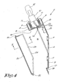
- the wall light fitting 1 mainly consists of a basic element 2 and a shade 3.
- the basic element 2 in this case mainly consists of a protruding part 4 with a circular cross section from which, in the longitudinal direction, a part of the casing has been removed and one far end of which has been cut slantwise, such that an elliptic intersecting line is formed there.
- a foot 5 which is formed in particular of a flat plate whose contour line corresponds to the above-mentioned elliptic intersecting line, as represented in greater detail in figures 3 , 4 and 5 .
- the other far end of the protruding part 4 is cut off crosswise and is internally provided with two longitudinally directed protrusions 8 which, via ribs 9, are connected to the casing of the protruding part 4, whereby these protrusions 8 reach up to the free end of the protruding part 4, and whereby threaded holes 9 are provided in these protrusions 8, in particular for fixing the lamp holder 10 by means of screws 11.
- a lamp 12 In the lamp holder 10 is provided a lamp 12.
- the lamp holder 10 is provided with electric cables 13 and 13A which run to a connecting strip 15 via an opening 14, provided against the inner side of the casing of the protruding part 4, in particular opposite the opening 16 which has been created by removing a part of the casing in the longitudinal direction.
- Figures 4 and 5 represent the lid 20 which mainly assumes the shape of the part of the casing of the protruding part 4 which has been removed in the longitudinal direction.
- This lid 20 is provided with a first protrusion 21 on one far end, and it is provided with a second protrusion 22 on the other far end.
- the edges 23 of the lid 20, which are mainly situated in the longitudinal direction, are provided with a shoulder 24 which works in conjunction with a non-represented groove along the corresponding edges of the basic element 2.
- the shade 3 comprises a tubular part 25 which is provided with a slantingly directed flat edge 26 on one far end, provided at an angle which is identical to the one formed between the foot 5 and the protruding part 4 of the basic element 2.
- the shade 3 is provided with a translucent cylinder 27 around which are provided circular discs 28, whereby a round disc 29 is connected to the free far end of the cylinder 27.
- the tubular part 25 of the shade 3 is provided with a duct-shaped passage 30 whose shape and inside dimensions mainly correspond to the shape and outside dimensions of the protruding part 4, in this case with a round cross section whose diameter is equal to or just slightly larger than the diameter of the protruding part 4 of the basic element 2.
- the non-represented feeder cable which is provided in the wall 31 and which comes out of the wall 31 at the height of the required fastening point is fed through the opening 6 of the foot 5, and the foot of the basic element 2 is held against the wall 31 at the required height and in the required direction, and it is fixed against the latter by means of screws which are not represented in the drawings and which are provided through the above-mentioned holes 7.
- the lid 20 is provided on the basic element 2, whereby first the protrusion 22 and then the protrusion 21 in the accompanying recesses 18, 19 respectively, is provided in the basic element 2.
- This lid 20 forms a secure protection against the supply voltage when the shade 3 is removed from the basic element 2, for example when replacing the lamp 12.
- the advantage of the wall light fitting 1 according to the invention is that the mounting is simple and that no tools are required to replace the lamp 12.
- the shade 3 must not have any openings and can be easily made water-tight, such that the wall light fitting according to the invention is very suitable for use in the open air.
- the protruding part 4 of the basic element 2 may also have a square or another cross section, and that the protruding part must not be tubular, as long as the shape of the passage 30 in the tubular part 25 of the shade 3 can be pushed over the protruding part 4 of the basic element 2.
- the predominantly duct-shaped passage 30 may have widenings, as long as the shape and the inside dimensions of the smallest section of the predominantly duct-shaped passage 30 correspond to or are somewhat larger than the shape and the outside dimensions of the largest section of the predominantly protruding part 4 of the basic element 2.
- the shape and the inside dimensions of the smallest section of the duct-shaped passage 30 must necessarily correspond to or be somewhat larger than the shape and the outside dimensions of the largest section of the predominantly protruding part 4 of the basic element 2, such over a sufficient length and/or on at least two sections situated away from each other.
- the embodiment represented in the figures has a foot 5 whose contour line falls within the extension of the predominantly protruding part 4 of the basic element 2. It is clear that the foot 5 may have larger outside dimensions than the outside dimensions of the protruding part 4. In the latter case, the shade 3 can be pushed against the foot 5.
- a recess may be provided in the oblique, flat far end of the shade 3 if necessary, whose shape and outside dimensions correspond to or are somewhat larger than the shape and the outside dimensions of the foot 5, and whose depth is at least as large as the thickness of the foot 5. In this manner is obtained a wall light fitting whose shade 3 can be pushed against the wall 31.
Landscapes
- Engineering & Computer Science (AREA)
- General Engineering & Computer Science (AREA)
- Architecture (AREA)
- Securing Globes, Refractors, Reflectors Or The Like (AREA)
- Arrangement Of Elements, Cooling, Sealing, Or The Like Of Lighting Devices (AREA)
- Road Signs Or Road Markings (AREA)
- Non-Portable Lighting Devices Or Systems Thereof (AREA)
Claims (7)
- Raccord pour l'applique d'éclairage (1) qui se compose principalement d'un élément de base (2) et d'un abat-jour (3), cas dans lequel l'élément de base (2) est au moins constitué d'un pied (5) qui est pourvu d'une face d'appui pour sa fixation contre une paroi (31) et d'une partie saillante (4) qui est prévue sur celle-ci, caractérisé en ce que, lorsque le raccord pour l'applique d'éclairage (1) est monté, la partie saillante (4) est dirigée obliquement vers le haut tandis que l'abat-jour (3) est pourvu d'un passage (30) d'une manière prédominante en forme de conduit à son extrémité inférieure dont la forme et les dimensions intérieures de la section transversale correspondent principalement à la forme et aux dimensions extérieures de la plus grande section transversale de la partie saillante (4) afin d'assurer que l'abat-jour (3) peut être poussé sur la partie saillante (4) et où l'abat-jour (3) comprend une partie tubulaire (25) qui est pourvue d'un bord plat (26) dirigé obliquement à une extrémité inférieure étant appliquée sous un angle qui est identique à celui étant formé entre le pied (5) et la partie saillante (4) de l'élément de base (2).
- Raccord pour l'applique d'éclairage selon la revendication 1, caractérisé en ce que la partie saillante (4) est rendue tubulaire.
- Raccord pour l'applique d'éclairage selon la revendication 1, caractérisé en ce que le bord plat (26), lorsque le raccord pour l'applique d'éclairage (1) est monté, est parallèle à la face d'appui du pied (5).
- Raccord pour l'applique d'éclairage selon la revendication 3, caractérisé en ce que le bord plat (26) est pourvu d'un évidement dont les dimensions intérieures sont au moins aussi grandes que les dimensions extérieures du pied (5).
- Raccord pour l'applique d'éclairage selon la revendication 1, caractérisé en ce que la forme et les dimensions du pied (5) sont telles que, lorsque le raccord pour l'applique d'éclairage (1) est monté, ce pied (5) est noyé dans le passage (30) en forme de conduit qui est mentionné dans ce qui précède.
- Raccord pour l'applique d'éclairage selon la revendication 1, caractérisé en ce que le bord plat (26) est pourvu d'un évidement dont les dimensions intérieures sont au moins aussi grandes que les dimensions extérieures du pied (5).
- Raccord pour l'applique d'éclairage selon la revendication 1, caractérisé en ce qu'une partie saillante (4) présente une section transversale circulaire et une extrémité inférieure de la partie saillante est ouverte et est coupée obliquement de telle façon qu'une ligne d'intersection elliptique soit formée à cet endroit.
Applications Claiming Priority (2)
| Application Number | Priority Date | Filing Date | Title |
|---|---|---|---|
| BE200300318 | 2003-05-23 | ||
| BE2003/0318A BE1015538A6 (nl) | 2003-05-23 | 2003-05-23 | Wandlichtarmatuur. |
Publications (3)
| Publication Number | Publication Date |
|---|---|
| EP1479965A2 EP1479965A2 (fr) | 2004-11-24 |
| EP1479965A3 EP1479965A3 (fr) | 2006-05-17 |
| EP1479965B1 true EP1479965B1 (fr) | 2009-09-02 |
Family
ID=33034888
Family Applications (1)
| Application Number | Title | Priority Date | Filing Date |
|---|---|---|---|
| EP04076471A Expired - Lifetime EP1479965B1 (fr) | 2003-05-23 | 2004-05-19 | Fixation pour applique |
Country Status (5)
| Country | Link |
|---|---|
| EP (1) | EP1479965B1 (fr) |
| AT (1) | ATE441808T1 (fr) |
| BE (1) | BE1015538A6 (fr) |
| DE (1) | DE602004022891D1 (fr) |
| ES (1) | ES2339859T3 (fr) |
Family Cites Families (3)
| Publication number | Priority date | Publication date | Assignee | Title |
|---|---|---|---|---|
| DE827681C (de) * | 1948-10-26 | 1952-01-14 | Hoppmann & Mulsow | Schraege Wandleuchte o. dgl. Geraet |
| US6224241B1 (en) * | 1996-07-01 | 2001-05-01 | Willi Wolfgang Oswald | Lighting device |
| US6386729B1 (en) * | 2000-06-30 | 2002-05-14 | Michael L. Bober | Landscape lighting apparatus |
-
2003
- 2003-05-23 BE BE2003/0318A patent/BE1015538A6/nl not_active IP Right Cessation
-
2004
- 2004-05-19 AT AT04076471T patent/ATE441808T1/de not_active IP Right Cessation
- 2004-05-19 EP EP04076471A patent/EP1479965B1/fr not_active Expired - Lifetime
- 2004-05-19 DE DE602004022891T patent/DE602004022891D1/de not_active Expired - Lifetime
- 2004-05-19 ES ES04076471T patent/ES2339859T3/es not_active Expired - Lifetime
Also Published As
| Publication number | Publication date |
|---|---|
| BE1015538A6 (nl) | 2005-06-07 |
| ES2339859T3 (es) | 2010-05-26 |
| ATE441808T1 (de) | 2009-09-15 |
| EP1479965A3 (fr) | 2006-05-17 |
| DE602004022891D1 (de) | 2009-10-15 |
| EP1479965A2 (fr) | 2004-11-24 |
Similar Documents
| Publication | Publication Date | Title |
|---|---|---|
| US12081004B2 (en) | Weatherproof electrical enclosure with reinforcement | |
| US20090213621A1 (en) | Luminaire profile | |
| US20040050423A1 (en) | Installation device for plumbing elements | |
| US20170122544A1 (en) | An underwater light fitting | |
| EP3179164B1 (fr) | Lampe tubulaire hermétique | |
| DE69719147D1 (de) | Bohrlochwerkzeuge mit mindestens einem Bohrlochwandkontaktelement | |
| US20090002978A1 (en) | Linear lighting system having a spinal structure and an optical system separately installable thereon | |
| GB2338545B (en) | Lighting fixture assembly | |
| NO303028B1 (no) | Undervannsinstallasjon | |
| KR20220169786A (ko) | 출몰형 브래킷을 구비한 매입등 | |
| GB9923135D0 (en) | Wellhead housing seal assembly with back up feature | |
| US7261446B2 (en) | Light assembly for a vehicle | |
| US20170002984A1 (en) | Led light fixtures and led lamps that are used to replace par 36 halogen lamps and incandescent well lights | |
| EP1479965B1 (fr) | Fixation pour applique | |
| DE69933920D1 (de) | Rohrdichtung mit einem niedrigen einführungsprofil | |
| JP2004146213A (ja) | ボックス埋込型照明器具 | |
| FR2784807B1 (fr) | Socle de prise de courant a obturateur de securite | |
| KR20220093686A (ko) | 천장 매립등 | |
| JP5057571B2 (ja) | 照明器具 | |
| US20050117331A1 (en) | Light housing | |
| KR102904344B1 (ko) | 엘이디 조명등장치 | |
| KR200451947Y1 (ko) | 천정 보수용 커버 | |
| KR100854311B1 (ko) | 매립형 조명등의 커버하우징 | |
| ATE333160T1 (de) | Mehrteilige abdeckung für elektroinstallationseinsätze | |
| EP0836367A2 (fr) | Dispositif de câblage étanche, en particulier pour système d'éclairage halogène, de préférence monté sur plaque de support |
Legal Events
| Date | Code | Title | Description |
|---|---|---|---|
| PUAI | Public reference made under article 153(3) epc to a published international application that has entered the european phase |
Free format text: ORIGINAL CODE: 0009012 |
|
| AK | Designated contracting states |
Kind code of ref document: A2 Designated state(s): AT BE BG CH CY CZ DE DK EE ES FI FR GB GR HU IE IT LI LU MC NL PL PT RO SE SI SK TR |
|
| AX | Request for extension of the european patent |
Extension state: AL HR LT LV MK |
|
| PUAL | Search report despatched |
Free format text: ORIGINAL CODE: 0009013 |
|
| AK | Designated contracting states |
Kind code of ref document: A3 Designated state(s): AT BE BG CH CY CZ DE DK EE ES FI FR GB GR HU IE IT LI LU MC NL PL PT RO SE SI SK TR |
|
| AX | Request for extension of the european patent |
Extension state: AL HR LT LV MK |
|
| 17P | Request for examination filed |
Effective date: 20061019 |
|
| 17Q | First examination report despatched |
Effective date: 20061208 |
|
| AKX | Designation fees paid |
Designated state(s): AT BE BG CH CY CZ DE DK EE ES FI FR GB GR HU IE IT LI LU MC NL PL PT RO SE SI SK TR |
|
| RAP1 | Party data changed (applicant data changed or rights of an application transferred) |
Owner name: MASSIVE, NAAMLOZE VENNOOTSCHAP |
|
| GRAP | Despatch of communication of intention to grant a patent |
Free format text: ORIGINAL CODE: EPIDOSNIGR1 |
|
| GRAS | Grant fee paid |
Free format text: ORIGINAL CODE: EPIDOSNIGR3 |
|
| GRAA | (expected) grant |
Free format text: ORIGINAL CODE: 0009210 |
|
| AK | Designated contracting states |
Kind code of ref document: B1 Designated state(s): AT BE BG CH CY CZ DE DK EE ES FI FR GB GR HU IE IT LI LU MC NL PL PT RO SE SI SK TR |
|
| REG | Reference to a national code |
Ref country code: CH Ref legal event code: EP |
|
| REG | Reference to a national code |
Ref country code: IE Ref legal event code: FG4D |
|
| REF | Corresponds to: |
Ref document number: 602004022891 Country of ref document: DE Date of ref document: 20091015 Kind code of ref document: P |
|
| PG25 | Lapsed in a contracting state [announced via postgrant information from national office to epo] |
Ref country code: FI Free format text: LAPSE BECAUSE OF FAILURE TO SUBMIT A TRANSLATION OF THE DESCRIPTION OR TO PAY THE FEE WITHIN THE PRESCRIBED TIME-LIMIT Effective date: 20090902 Ref country code: SE Free format text: LAPSE BECAUSE OF FAILURE TO SUBMIT A TRANSLATION OF THE DESCRIPTION OR TO PAY THE FEE WITHIN THE PRESCRIBED TIME-LIMIT Effective date: 20090902 |
|
| NLV1 | Nl: lapsed or annulled due to failure to fulfill the requirements of art. 29p and 29m of the patents act | ||
| PG25 | Lapsed in a contracting state [announced via postgrant information from national office to epo] |
Ref country code: SI Free format text: LAPSE BECAUSE OF FAILURE TO SUBMIT A TRANSLATION OF THE DESCRIPTION OR TO PAY THE FEE WITHIN THE PRESCRIBED TIME-LIMIT Effective date: 20090902 Ref country code: NL Free format text: LAPSE BECAUSE OF FAILURE TO SUBMIT A TRANSLATION OF THE DESCRIPTION OR TO PAY THE FEE WITHIN THE PRESCRIBED TIME-LIMIT Effective date: 20090902 Ref country code: PL Free format text: LAPSE BECAUSE OF FAILURE TO SUBMIT A TRANSLATION OF THE DESCRIPTION OR TO PAY THE FEE WITHIN THE PRESCRIBED TIME-LIMIT Effective date: 20090902 |
|
| PG25 | Lapsed in a contracting state [announced via postgrant information from national office to epo] |
Ref country code: CY Free format text: LAPSE BECAUSE OF FAILURE TO SUBMIT A TRANSLATION OF THE DESCRIPTION OR TO PAY THE FEE WITHIN THE PRESCRIBED TIME-LIMIT Effective date: 20090902 |
|
| PG25 | Lapsed in a contracting state [announced via postgrant information from national office to epo] |
Ref country code: RO Free format text: LAPSE BECAUSE OF FAILURE TO SUBMIT A TRANSLATION OF THE DESCRIPTION OR TO PAY THE FEE WITHIN THE PRESCRIBED TIME-LIMIT Effective date: 20090902 Ref country code: CZ Free format text: LAPSE BECAUSE OF FAILURE TO SUBMIT A TRANSLATION OF THE DESCRIPTION OR TO PAY THE FEE WITHIN THE PRESCRIBED TIME-LIMIT Effective date: 20090902 Ref country code: EE Free format text: LAPSE BECAUSE OF FAILURE TO SUBMIT A TRANSLATION OF THE DESCRIPTION OR TO PAY THE FEE WITHIN THE PRESCRIBED TIME-LIMIT Effective date: 20090902 Ref country code: PT Free format text: LAPSE BECAUSE OF FAILURE TO SUBMIT A TRANSLATION OF THE DESCRIPTION OR TO PAY THE FEE WITHIN THE PRESCRIBED TIME-LIMIT Effective date: 20100104 |
|
| REG | Reference to a national code |
Ref country code: ES Ref legal event code: FG2A Ref document number: 2339859 Country of ref document: ES Kind code of ref document: T3 |
|
| PG25 | Lapsed in a contracting state [announced via postgrant information from national office to epo] |
Ref country code: SK Free format text: LAPSE BECAUSE OF FAILURE TO SUBMIT A TRANSLATION OF THE DESCRIPTION OR TO PAY THE FEE WITHIN THE PRESCRIBED TIME-LIMIT Effective date: 20090902 |
|
| PG25 | Lapsed in a contracting state [announced via postgrant information from national office to epo] |
Ref country code: BE Free format text: LAPSE BECAUSE OF FAILURE TO SUBMIT A TRANSLATION OF THE DESCRIPTION OR TO PAY THE FEE WITHIN THE PRESCRIBED TIME-LIMIT Effective date: 20090902 Ref country code: AT Free format text: LAPSE BECAUSE OF FAILURE TO SUBMIT A TRANSLATION OF THE DESCRIPTION OR TO PAY THE FEE WITHIN THE PRESCRIBED TIME-LIMIT Effective date: 20090902 |
|
| PLBE | No opposition filed within time limit |
Free format text: ORIGINAL CODE: 0009261 |
|
| STAA | Information on the status of an ep patent application or granted ep patent |
Free format text: STATUS: NO OPPOSITION FILED WITHIN TIME LIMIT |
|
| PG25 | Lapsed in a contracting state [announced via postgrant information from national office to epo] |
Ref country code: DK Free format text: LAPSE BECAUSE OF FAILURE TO SUBMIT A TRANSLATION OF THE DESCRIPTION OR TO PAY THE FEE WITHIN THE PRESCRIBED TIME-LIMIT Effective date: 20090902 |
|
| 26N | No opposition filed |
Effective date: 20100603 |
|
| PG25 | Lapsed in a contracting state [announced via postgrant information from national office to epo] |
Ref country code: GR Free format text: LAPSE BECAUSE OF FAILURE TO SUBMIT A TRANSLATION OF THE DESCRIPTION OR TO PAY THE FEE WITHIN THE PRESCRIBED TIME-LIMIT Effective date: 20091203 |
|
| PG25 | Lapsed in a contracting state [announced via postgrant information from national office to epo] |
Ref country code: MC Free format text: LAPSE BECAUSE OF NON-PAYMENT OF DUE FEES Effective date: 20100531 |
|
| REG | Reference to a national code |
Ref country code: CH Ref legal event code: PL |
|
| PG25 | Lapsed in a contracting state [announced via postgrant information from national office to epo] |
Ref country code: CH Free format text: LAPSE BECAUSE OF NON-PAYMENT OF DUE FEES Effective date: 20100531 Ref country code: LI Free format text: LAPSE BECAUSE OF NON-PAYMENT OF DUE FEES Effective date: 20100531 |
|
| PG25 | Lapsed in a contracting state [announced via postgrant information from national office to epo] |
Ref country code: IE Free format text: LAPSE BECAUSE OF NON-PAYMENT OF DUE FEES Effective date: 20100519 |
|
| PGFP | Annual fee paid to national office [announced via postgrant information from national office to epo] |
Ref country code: ES Payment date: 20110627 Year of fee payment: 8 Ref country code: FR Payment date: 20110615 Year of fee payment: 8 |
|
| PGFP | Annual fee paid to national office [announced via postgrant information from national office to epo] |
Ref country code: GB Payment date: 20110531 Year of fee payment: 8 |
|
| PGFP | Annual fee paid to national office [announced via postgrant information from national office to epo] |
Ref country code: IT Payment date: 20110528 Year of fee payment: 8 |
|
| PGFP | Annual fee paid to national office [announced via postgrant information from national office to epo] |
Ref country code: DE Payment date: 20110728 Year of fee payment: 8 |
|
| PG25 | Lapsed in a contracting state [announced via postgrant information from national office to epo] |
Ref country code: HU Free format text: LAPSE BECAUSE OF FAILURE TO SUBMIT A TRANSLATION OF THE DESCRIPTION OR TO PAY THE FEE WITHIN THE PRESCRIBED TIME-LIMIT Effective date: 20100303 Ref country code: BG Free format text: LAPSE BECAUSE OF FAILURE TO SUBMIT A TRANSLATION OF THE DESCRIPTION OR TO PAY THE FEE WITHIN THE PRESCRIBED TIME-LIMIT Effective date: 20090902 Ref country code: LU Free format text: LAPSE BECAUSE OF NON-PAYMENT OF DUE FEES Effective date: 20100519 |
|
| PG25 | Lapsed in a contracting state [announced via postgrant information from national office to epo] |
Ref country code: TR Free format text: LAPSE BECAUSE OF FAILURE TO SUBMIT A TRANSLATION OF THE DESCRIPTION OR TO PAY THE FEE WITHIN THE PRESCRIBED TIME-LIMIT Effective date: 20090902 |
|
| GBPC | Gb: european patent ceased through non-payment of renewal fee |
Effective date: 20120519 |
|
| PG25 | Lapsed in a contracting state [announced via postgrant information from national office to epo] |
Ref country code: IT Free format text: LAPSE BECAUSE OF NON-PAYMENT OF DUE FEES Effective date: 20120519 |
|
| REG | Reference to a national code |
Ref country code: FR Ref legal event code: ST Effective date: 20130131 |
|
| REG | Reference to a national code |
Ref country code: DE Ref legal event code: R119 Ref document number: 602004022891 Country of ref document: DE Effective date: 20121201 |
|
| PG25 | Lapsed in a contracting state [announced via postgrant information from national office to epo] |
Ref country code: FR Free format text: LAPSE BECAUSE OF NON-PAYMENT OF DUE FEES Effective date: 20120531 Ref country code: GB Free format text: LAPSE BECAUSE OF NON-PAYMENT OF DUE FEES Effective date: 20120519 |
|
| PG25 | Lapsed in a contracting state [announced via postgrant information from national office to epo] |
Ref country code: DE Free format text: LAPSE BECAUSE OF NON-PAYMENT OF DUE FEES Effective date: 20121201 |
|
| REG | Reference to a national code |
Ref country code: ES Ref legal event code: FD2A Effective date: 20131030 |
|
| PG25 | Lapsed in a contracting state [announced via postgrant information from national office to epo] |
Ref country code: ES Free format text: LAPSE BECAUSE OF NON-PAYMENT OF DUE FEES Effective date: 20120520 |