EP1479936B1 - Controller of electromagnetic clutch - Google Patents
Controller of electromagnetic clutch Download PDFInfo
- Publication number
- EP1479936B1 EP1479936B1 EP02701639A EP02701639A EP1479936B1 EP 1479936 B1 EP1479936 B1 EP 1479936B1 EP 02701639 A EP02701639 A EP 02701639A EP 02701639 A EP02701639 A EP 02701639A EP 1479936 B1 EP1479936 B1 EP 1479936B1
- Authority
- EP
- European Patent Office
- Prior art keywords
- electromagnetic clutch
- field
- field coil
- excitation
- planetary gear
- Prior art date
- Legal status (The legal status is an assumption and is not a legal conclusion. Google has not performed a legal analysis and makes no representation as to the accuracy of the status listed.)
- Expired - Fee Related
Links
Images


Classifications
-
- H—ELECTRICITY
- H02—GENERATION; CONVERSION OR DISTRIBUTION OF ELECTRIC POWER
- H02P—CONTROL OR REGULATION OF ELECTRIC MOTORS, ELECTRIC GENERATORS OR DYNAMO-ELECTRIC CONVERTERS; CONTROLLING TRANSFORMERS, REACTORS OR CHOKE COILS
- H02P15/00—Arrangements for controlling dynamo-electric brakes or clutches
-
- F—MECHANICAL ENGINEERING; LIGHTING; HEATING; WEAPONS; BLASTING
- F02—COMBUSTION ENGINES; HOT-GAS OR COMBUSTION-PRODUCT ENGINE PLANTS
- F02N—STARTING OF COMBUSTION ENGINES; STARTING AIDS FOR SUCH ENGINES, NOT OTHERWISE PROVIDED FOR
- F02N15/00—Other power-operated starting apparatus; Component parts, details, or accessories, not provided for in, or of interest apart from groups F02N5/00 - F02N13/00
- F02N15/02—Gearing between starting-engines and started engines; Engagement or disengagement thereof
- F02N15/022—Gearing between starting-engines and started engines; Engagement or disengagement thereof the starter comprising an intermediate clutch
- F02N15/025—Gearing between starting-engines and started engines; Engagement or disengagement thereof the starter comprising an intermediate clutch of the friction type
-
- F—MECHANICAL ENGINEERING; LIGHTING; HEATING; WEAPONS; BLASTING
- F16—ENGINEERING ELEMENTS AND UNITS; GENERAL MEASURES FOR PRODUCING AND MAINTAINING EFFECTIVE FUNCTIONING OF MACHINES OR INSTALLATIONS; THERMAL INSULATION IN GENERAL
- F16D—COUPLINGS FOR TRANSMITTING ROTATION; CLUTCHES; BRAKES
- F16D27/00—Magnetically- or electrically- actuated clutches; Control or electric circuits therefor
- F16D27/10—Magnetically- or electrically- actuated clutches; Control or electric circuits therefor with an electromagnet not rotating with a clutching member, i.e. without collecting rings
- F16D27/108—Magnetically- or electrically- actuated clutches; Control or electric circuits therefor with an electromagnet not rotating with a clutching member, i.e. without collecting rings with axially movable clutching members
-
- F—MECHANICAL ENGINEERING; LIGHTING; HEATING; WEAPONS; BLASTING
- F16—ENGINEERING ELEMENTS AND UNITS; GENERAL MEASURES FOR PRODUCING AND MAINTAINING EFFECTIVE FUNCTIONING OF MACHINES OR INSTALLATIONS; THERMAL INSULATION IN GENERAL
- F16D—COUPLINGS FOR TRANSMITTING ROTATION; CLUTCHES; BRAKES
- F16D27/00—Magnetically- or electrically- actuated clutches; Control or electric circuits therefor
- F16D27/10—Magnetically- or electrically- actuated clutches; Control or electric circuits therefor with an electromagnet not rotating with a clutching member, i.e. without collecting rings
- F16D27/118—Magnetically- or electrically- actuated clutches; Control or electric circuits therefor with an electromagnet not rotating with a clutching member, i.e. without collecting rings with interengaging jaws or gear teeth
-
- F—MECHANICAL ENGINEERING; LIGHTING; HEATING; WEAPONS; BLASTING
- F16—ENGINEERING ELEMENTS AND UNITS; GENERAL MEASURES FOR PRODUCING AND MAINTAINING EFFECTIVE FUNCTIONING OF MACHINES OR INSTALLATIONS; THERMAL INSULATION IN GENERAL
- F16D—COUPLINGS FOR TRANSMITTING ROTATION; CLUTCHES; BRAKES
- F16D48/00—External control of clutches
- F16D48/06—Control by electric or electronic means, e.g. of fluid pressure
- F16D48/064—Control of electrically or electromagnetically actuated clutches
-
- F—MECHANICAL ENGINEERING; LIGHTING; HEATING; WEAPONS; BLASTING
- F02—COMBUSTION ENGINES; HOT-GAS OR COMBUSTION-PRODUCT ENGINE PLANTS
- F02N—STARTING OF COMBUSTION ENGINES; STARTING AIDS FOR SUCH ENGINES, NOT OTHERWISE PROVIDED FOR
- F02N11/00—Starting of engines by means of electric motors
- F02N11/04—Starting of engines by means of electric motors the motors being associated with current generators
-
- F—MECHANICAL ENGINEERING; LIGHTING; HEATING; WEAPONS; BLASTING
- F16—ENGINEERING ELEMENTS AND UNITS; GENERAL MEASURES FOR PRODUCING AND MAINTAINING EFFECTIVE FUNCTIONING OF MACHINES OR INSTALLATIONS; THERMAL INSULATION IN GENERAL
- F16D—COUPLINGS FOR TRANSMITTING ROTATION; CLUTCHES; BRAKES
- F16D27/00—Magnetically- or electrically- actuated clutches; Control or electric circuits therefor
- F16D2027/002—Electric or electronic circuits relating to actuation of electromagnetic clutches
-
- F—MECHANICAL ENGINEERING; LIGHTING; HEATING; WEAPONS; BLASTING
- F16—ENGINEERING ELEMENTS AND UNITS; GENERAL MEASURES FOR PRODUCING AND MAINTAINING EFFECTIVE FUNCTIONING OF MACHINES OR INSTALLATIONS; THERMAL INSULATION IN GENERAL
- F16D—COUPLINGS FOR TRANSMITTING ROTATION; CLUTCHES; BRAKES
- F16D2500/00—External control of clutches by electric or electronic means
- F16D2500/10—System to be controlled
- F16D2500/102—Actuator
- F16D2500/1021—Electrical type
- F16D2500/1022—Electromagnet
-
- F—MECHANICAL ENGINEERING; LIGHTING; HEATING; WEAPONS; BLASTING
- F16—ENGINEERING ELEMENTS AND UNITS; GENERAL MEASURES FOR PRODUCING AND MAINTAINING EFFECTIVE FUNCTIONING OF MACHINES OR INSTALLATIONS; THERMAL INSULATION IN GENERAL
- F16D—COUPLINGS FOR TRANSMITTING ROTATION; CLUTCHES; BRAKES
- F16D2500/00—External control of clutches by electric or electronic means
- F16D2500/10—System to be controlled
- F16D2500/104—Clutch
- F16D2500/10406—Clutch position
- F16D2500/10412—Transmission line of a vehicle
-
- F—MECHANICAL ENGINEERING; LIGHTING; HEATING; WEAPONS; BLASTING
- F16—ENGINEERING ELEMENTS AND UNITS; GENERAL MEASURES FOR PRODUCING AND MAINTAINING EFFECTIVE FUNCTIONING OF MACHINES OR INSTALLATIONS; THERMAL INSULATION IN GENERAL
- F16D—COUPLINGS FOR TRANSMITTING ROTATION; CLUTCHES; BRAKES
- F16D2500/00—External control of clutches by electric or electronic means
- F16D2500/10—System to be controlled
- F16D2500/108—Gear
- F16D2500/1087—Planetary gearing
-
- F—MECHANICAL ENGINEERING; LIGHTING; HEATING; WEAPONS; BLASTING
- F16—ENGINEERING ELEMENTS AND UNITS; GENERAL MEASURES FOR PRODUCING AND MAINTAINING EFFECTIVE FUNCTIONING OF MACHINES OR INSTALLATIONS; THERMAL INSULATION IN GENERAL
- F16D—COUPLINGS FOR TRANSMITTING ROTATION; CLUTCHES; BRAKES
- F16D2500/00—External control of clutches by electric or electronic means
- F16D2500/30—Signal inputs
- F16D2500/304—Signal inputs from the clutch
- F16D2500/3041—Signal inputs from the clutch from the input shaft
- F16D2500/30415—Speed of the input shaft
-
- F—MECHANICAL ENGINEERING; LIGHTING; HEATING; WEAPONS; BLASTING
- F16—ENGINEERING ELEMENTS AND UNITS; GENERAL MEASURES FOR PRODUCING AND MAINTAINING EFFECTIVE FUNCTIONING OF MACHINES OR INSTALLATIONS; THERMAL INSULATION IN GENERAL
- F16D—COUPLINGS FOR TRANSMITTING ROTATION; CLUTCHES; BRAKES
- F16D2500/00—External control of clutches by electric or electronic means
- F16D2500/30—Signal inputs
- F16D2500/31—Signal inputs from the vehicle
- F16D2500/3108—Vehicle speed
-
- F—MECHANICAL ENGINEERING; LIGHTING; HEATING; WEAPONS; BLASTING
- F16—ENGINEERING ELEMENTS AND UNITS; GENERAL MEASURES FOR PRODUCING AND MAINTAINING EFFECTIVE FUNCTIONING OF MACHINES OR INSTALLATIONS; THERMAL INSULATION IN GENERAL
- F16D—COUPLINGS FOR TRANSMITTING ROTATION; CLUTCHES; BRAKES
- F16D2500/00—External control of clutches by electric or electronic means
- F16D2500/30—Signal inputs
- F16D2500/316—Other signal inputs not covered by the groups above
- F16D2500/3166—Detection of an elapsed period of time
-
- F—MECHANICAL ENGINEERING; LIGHTING; HEATING; WEAPONS; BLASTING
- F16—ENGINEERING ELEMENTS AND UNITS; GENERAL MEASURES FOR PRODUCING AND MAINTAINING EFFECTIVE FUNCTIONING OF MACHINES OR INSTALLATIONS; THERMAL INSULATION IN GENERAL
- F16D—COUPLINGS FOR TRANSMITTING ROTATION; CLUTCHES; BRAKES
- F16D2500/00—External control of clutches by electric or electronic means
- F16D2500/50—Problem to be solved by the control system
- F16D2500/502—Relating the clutch
- F16D2500/50224—Drive-off
-
- F—MECHANICAL ENGINEERING; LIGHTING; HEATING; WEAPONS; BLASTING
- F16—ENGINEERING ELEMENTS AND UNITS; GENERAL MEASURES FOR PRODUCING AND MAINTAINING EFFECTIVE FUNCTIONING OF MACHINES OR INSTALLATIONS; THERMAL INSULATION IN GENERAL
- F16D—COUPLINGS FOR TRANSMITTING ROTATION; CLUTCHES; BRAKES
- F16D2500/00—External control of clutches by electric or electronic means
- F16D2500/50—Problem to be solved by the control system
- F16D2500/502—Relating the clutch
- F16D2500/50293—Reduction of vibrations
-
- F—MECHANICAL ENGINEERING; LIGHTING; HEATING; WEAPONS; BLASTING
- F16—ENGINEERING ELEMENTS AND UNITS; GENERAL MEASURES FOR PRODUCING AND MAINTAINING EFFECTIVE FUNCTIONING OF MACHINES OR INSTALLATIONS; THERMAL INSULATION IN GENERAL
- F16D—COUPLINGS FOR TRANSMITTING ROTATION; CLUTCHES; BRAKES
- F16D2500/00—External control of clutches by electric or electronic means
- F16D2500/70—Details about the implementation of the control system
- F16D2500/704—Output parameters from the control unit; Target parameters to be controlled
- F16D2500/70402—Actuator parameters
- F16D2500/7042—Voltage
-
- F—MECHANICAL ENGINEERING; LIGHTING; HEATING; WEAPONS; BLASTING
- F16—ENGINEERING ELEMENTS AND UNITS; GENERAL MEASURES FOR PRODUCING AND MAINTAINING EFFECTIVE FUNCTIONING OF MACHINES OR INSTALLATIONS; THERMAL INSULATION IN GENERAL
- F16D—COUPLINGS FOR TRANSMITTING ROTATION; CLUTCHES; BRAKES
- F16D2500/00—External control of clutches by electric or electronic means
- F16D2500/70—Details about the implementation of the control system
- F16D2500/71—Actions
- F16D2500/7107—Others
- F16D2500/7109—Pulsed signal; Generating or processing pulsed signals; PWM, width modulation, frequency or amplitude modulation
-
- F—MECHANICAL ENGINEERING; LIGHTING; HEATING; WEAPONS; BLASTING
- F16—ENGINEERING ELEMENTS AND UNITS; GENERAL MEASURES FOR PRODUCING AND MAINTAINING EFFECTIVE FUNCTIONING OF MACHINES OR INSTALLATIONS; THERMAL INSULATION IN GENERAL
- F16H—GEARING
- F16H1/00—Toothed gearings for conveying rotary motion
- F16H1/28—Toothed gearings for conveying rotary motion with gears having orbital motion
Landscapes
- Engineering & Computer Science (AREA)
- General Engineering & Computer Science (AREA)
- Physics & Mathematics (AREA)
- Mechanical Engineering (AREA)
- Electromagnetism (AREA)
- Power Engineering (AREA)
- Fluid Mechanics (AREA)
- Chemical & Material Sciences (AREA)
- Combustion & Propulsion (AREA)
- Hydraulic Clutches, Magnetic Clutches, Fluid Clutches, And Fluid Joints (AREA)
Abstract
Description
- The present invention relates to an electromagnetic clutch for a rotating electric machine of a motor vehicle. More particularly, the present invention is concerned with the control apparatus for controlling the electromagnetic clutch so as to suppress generation of harsh or loud collision noise.
-
Figure 7 is a sectional view of a conventional rotating electric machine for a motor vehicle (hereinafter referred to simply as the rotating electric machine) known heretofore. The rotating electric machine is comprised of afirst bracket 80, arotor 100 of landaulet type fixedly mounted on arotor shaft 12 disposed internally of thefirst bracket 80, astator 101 secured to the inner wall surface of thefirst bracket 80,slip rings 15 secured to therotor shaft 12 at an end portion thereof for supplying an electric current to therotor 100, a pair ofbrushes 13 which are in slideable contract with the surfaces of theslip rings 15, and abrush holder 102 housing therein thebrushes 13 andsprings 14 pressing thebrushes 13, respectively. - The
rotor 100 is composed of a field winding 11 for generating magnetic flux under the effect of the electric current flowing through the field winding, and arotor core 10 encasing the field winding 11 therein. Thestator 101 is composed of astator core 1 formed by laminating or stacking a plurality of steel sheets through which the magnetic flux generated by the field winding 11 passes, and a three-phase stator winding 2 through which a three-phase alternating current flows. - Further, the rotating electric machine is equipped with an
electromagnetic clutch 110 disposed internally of asecond bracket 81, aplanetary gear mechanism 111, apulley 60 and a one-way clutch 113. - The
electromagnetic clutch 110 mentioned above is composed of anelectromagnetic clutch body 70 fixedly secured to thesecond bracket 81 by means of alocking screw 72 and afixing key 79, afield coil 71 disposed internally in theelectromagnetic clutch body 70, an electromagneticclutch follower member 73 secured to thefirst bracket 80 by means of alocking screw 75 through an interposedhold member 77 in opposition to theelectromagnetic clutch body 70 and having anengaging portion 76 formed along a diametrically inner peripheral portion, and aspring 74 disposed between the electromagnetic clutch follower member 73and a head of thelocking screw 75 for resiliently urging the electromagneticclutch follower member 73 toward theelectromagnetic clutch body 70. - Formed in the outer peripheral surface of the
hold member 77 is aguide face 77a in which aguide face 73b formed in the inner peripheral surface of the electromagneticclutch follower member 73 engages slideably in the axial direction. In this manner, the electromagneticclutch follower member 73 is assembled together with thehold member 77. Incidentally, although thehold member 77 is shown as being formed as a discrete member separated from thefirst bracket 80, the former may be formed integrally with the latter. - The
planetary gear mechanism 111 mentioned previously is composed of asun gear 20, acylindrical member 40 including anengaging portion 42 formed at an end face and adapted to engage with theengaging portion 76 of theelectromagnetic clutch body 70 and aninternal gear 41 formed in the inner wall surface,bearings 44 disposed between an inner end surface of thecylindrical member 40 and an end portion of thefirst bracket 80, aplanetary gear 30 meshing with theinternal gear 41 and thesun gear 20, respectively, acarrier 61 which supports rotatably theplanetary gear 30 through the medium of aplanetary gear shaft 65 extending through a center portion of theplanetary gear 30 and which is formed integrally with thepulley 60, and abearing 54 disposed between thecarrier 61 and thecylindrical member 40 at respective end portions. - The one-
way clutch 113 mentioned previously includes acam portion 52 provided on the inner side of thecarrier 61,bearings 53 provided on both sides of the cam portion, and acam follower member 50 fixedly secured together with thesun gear 20 to therotor shaft 12 at respective end portions by means of afixing key 22. - Further, in
Fig. 2 ,reference numerals - Next, description will be made of operation of the rotating electric machine implemented in the structure described above.
- Firstly, operation of the rotating electric machine in the motor mode will be described.
- Upon starting of an engine, the
field coil 71 of theelectromagnetic clutch 110 is electrically energized, as a result of which the electromagneticclutch follower member 73 is forced to bear onto theelectromagnetic clutch body 70 against the elastic force of thespring 74. Thus, theengaging portion 76 of the electromagneticclutch follower member 73 is caused to engage with theengaging portion 42 of thecylindrical member 40. - As a result of this, the
internal gear 41 of thecylindrical member 40 operates as a stationary element, whereby deceleration at the reduction gear ratio of theplanetary gear mechanism 111 is realized in the state where the turning force or torque of therotor 100 is transmitted to thesun gear 20 which is thus caused to rotate about it's own axis with theplanetary gear 30 revolving around thesun gear 20 while rotating about theplanetary gear shaft 65. - In accompaniment with the revolution of the
planetary gear 30, thepulley 60 formed integrally with thecarrier 61 serving as the output element is caused to rotate, as a result of which turning force or torque is transmitted to the engine through the medium of a belt (not shown) wound around thepulley 60 for starting the engine operation. In this state, the one-way clutch 113 operates idly. Consequently, the engine is driven at a speed corresponding to a product of multiplication of the rotation speed of therotor 100 by the reduction gear ratios of theplanetary gear mechanism 111 and thepulley 60, respectively. - Incidentally, the turning force or torque of the
rotor 100 is generated by supplying a three-phase alternating current to the three-phase stator winding 2 in the state where an exciting current is fed to the field winding 11 from a battery (not shown) through thebrush 13 and theslip ring 15 and thus the magnetic flux is generated through therotor core 10. - Next, description will be directed to operation of the rotating electric machine in the generator mode.
- When the electric power is fed from the rotating electric machine operating in the generator mode, the electromagnetic
clutch follower member 73 is detached from theelectromagnetic clutch body 70 under the elastic force of thespring 74, whereby theengaging portion 76 of the electromagneticclutch follower member 73 and theengaging portion 42 of thecylindrical member 40 are disengaged from each other, rendering thecylindrical member 40 to be rotatable. In this state, the motive power of the engine is transmitted to thecarrier 61 serving as the input element by way of thepulley 60. Since the one-way clutch 113 is coupled in this state, therotor 100 is caused to rotate in unison with thecarrier 61 through therotor shaft 12, whereby an electromotive force is induced in the three-phase stator winding 2. -
Figure 8 is a circuit diagram showing a fieldcurrent control circuit 120 for theelectromagnetic clutch 110 known heretofore. Further,Fig. 9 is a timing chart for illustrating the field current control, wherein a voltage making appearance across the field coil upon the field current control is shown at (a) with the direction and magnitude of the field current being shown at (b).Figure 10 is a view for illustrating a relation between the magnetic field intensity and the magnetic flux density due to the field current mentioned above. - According to the method of controlling the electromagnetic clutch for the rotating electric machine of the structure described above, the field current Ia(+) flowing through the
field coil 71 is simply turned on and off, as shown inFig. 9 at (a) and (b) . Consequently, in the operation of the electromagnetic clutch upon starting of the engine operation, the electromagneticclutch follower member 73 is attracted to theelectromagnetic clutch body 70 to engage therewith with one rush. Thus, there arises a problem that harsh or loud coupling noise is generated upon coupling of the electromagnetic clutch. - Further, for changing over to the generator operation mode, electric energization of the
field coil 71 is simply interrupted. As a consequence, residual magnetic flux continues to exist in the magnetic circuit of the electromagnetic clutch, as can be seen fromFig. 10 . For this reason, there arises such situation that the electromagneticclutch follower member 73 can not disengage completely from theelectromagnetic clutch body 70 or the electromagneticclutch follower member 73 tends to remain partially sticking to theelectromagnetic clutch body 70 with inclination, as a result of which theengaging portion 42 of thecylindrical member 40 caused to rotate by way of thepulley 60, thecarrier 61, theplanetary gear shaft 65, theplanetary gear 30, theinternal gear 41 and thecylindrical member 40 strikes against theengaging portion 76 of the electromagneticclutch follower member 73, to thereby generate loud collision noise, giving rise to a problem. -
US 5,492,194 discloses an on demand four-wheel drive system comprising a microcontroller and a modulating electromagnetic clutch assembly controlled by the microcontroller. The clutch current is incrementally increased or decreased to increase or decrease torque transfer between a primary output shaft and a secondary output shaft. - The present invention has been made with a view to solving the problems such as mentioned above, and thus an object of the present invention is to provide a control apparatus for the electromagnetic clutch which apparatus is capable of solving the problem that the electromagnetic clutch follower member can not be detached from the electromagnetic clutch body or the former tends to remain partially sticking to the latter under the influence of the residual magnetic flux, as a result of which the electromagnetic clutch follower member is inclined to strike against the electromagnetic clutch body, whereby loud or harsh collision noise is generated.
- The present invention provides an electromagnetic clutch according to
claim 1 - The field coil of the electromagnetic clutch is constituted by a plurality of field coils, wherein a field current of a same direction is caused to flow through any one of the plurality of field coils while the other field coil is supplied with the field current alternately in one direction and in the other direction opposite to the one direction.
- Further, a pulse-width modulating circuit may be employed as the excitation attenuating means.
- Moreover, first and second Zener diodes may be connected across the field coil of the electromagnetic clutch in parallel with the field coil with the first and second Zener diodes being connected in series with polarities opposite to each other.
- Furthermore, the excitation attenuating means may be so arranged as to decrease the field current to a prescribed current or alternatively diminish the excitation intensity to a prescribed value in the course of elapse of a predetermined time after an electromagnetic clutchfollower member and an electromagnetic clutch body of the electromagnetic clutch have been coupled to each other.
- Furthermore, the electromagnetic clutch may be implemented in combination with a rotating electric machine for a motor vehicle and capable of transmitting bidirectionally a motive power between an engine of the motor vehicle and the rotating electric machine through the medium of a power transmission mechanism, the rotating electric machine operating as an electric motor for starting engine operation and as an electric generator for supplying an electric power to the motor vehicle. The electromagnetic clutch may be implemented in combination with a rotor secured to a rotor shaft disposed internally of a bracket, a planetary gear mechanism including a sun gear secured to the rotor shaft at an end portion thereof, a planetary gear meshing with the sun gear, a cylindrical member having an internal gear formed in an inner wall surface thereof and meshing with the planetary gear and a carrier for supporting rotatably the planetary gear by means of a planetary gear shaft extending axially through the planetary gear at a center portion thereof, and a one-way clutch disposed on an inner side of the carrier for transmitting a turning force from the power transmission mechanism to the rotor shaft by way of the sun gear. The electromagnetic clutch is comprised of an electromagnetic clutch body secured to the bracket and an electromagnetic clutch follower member disposed in opposition to the electromagnetic clutch body movably to and away from the electromagnetic clutch. The electromagnetic clotch is as set forth in
claims 1. In the electric motor operation mode, the electromagnetic clutch follower member is brought into contact with the electromagnetic clutch body and engages the cylindrical member to thereby brake the cylindrical member, as a result of which the internal gear acts as a stationary element such that the turning force of the rotor is transmitted to the power transmission mechanism by way of the rotor shaft, the sun gear, the planetary gear and the carrier, while in the generator operation mode, the electromagnetic clutch follower member is moved away from the electromagnetic clutch body, as a result of which the turning force from the power transmission mechanism causes the carrier, the one-way clutch, the sun gear and the rotor shaft to rotate to thereby rotate the rotor. -
-
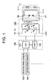
Figure 1 is a circuit diagram showing a control circuit for controlling a field current flowing through a field coil of an electromagnetic clutch not according the present invention. -
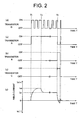
Figure 2 is a view for illustrating on/off states of transistors A, B, C and D of the field current control circuit in a timing chart together with corresponding changes in direction and magnitude of the field current Ia. -
Figure 3 is a view for illustrating a relation between magnetic field intensity and magnetic flux density in a magnetic circuit of the electromagnetic clutch when the field current Ia flows therethrough. -
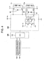
Figure 4 is a circuit diagram showing a control circuit for controlling a field current flowing through the field coil of the electromagnetic clutch according to the present invention. -
Figure 5 is a view for illustrating on/off states of transistors A, B, C and D of the field current control circuit in a timing chart together with corresponding changes in the direction and magnitude of the field currents Ia and Ib and the magnetic field intensity. -
Figure 6 is a view for illustrating a relation between the magnetic field intensity and the magnetic flux density in a magnetic circuit of the electromagnetic clutch when the field current Ia and the field current Ib are electrically energized. -
Figure 7 is a sectional view of a conventional rotating electric machine for a motor vehicle. -
Figure 8 is a circuit diagram showing a field current control circuit for the electromagnetic clutch known heretofore. -
Figure 9 is a timing chart for illustrating the field current control, wherein a voltage making appearance across a field coil upon field current control is shown at (a) while direction and magnitude of the field current at that time are shown at (b). -
Figure 10 is a view for illustrating a relation between the magnetic field intensity and the magnetic flux density due to the field current. -
Figure 1 is a circuit diagram showing a fieldcurrent control circuit 120 for a field coil of an electromagnetic clutch not according to the present invention.Figure 2 is a view for illustrating on/off states of transistors A, B, C and D of the fieldcurrent control circuit 120 in a timing chart together with corresponding changes in the direction and magnitude of the field current Ia.Figure 3 is a view for illustrating a relation between the magnetic field intensity of a magnetic circuit of the electromagnetic clutch and magnetic flux density when the above-mentioned field current Ia flows. - Referring to
Fig. 1 , the field current control circuit for the field coil of the electromagnetic clutch includes thefield coil 71, the fieldcurrent control circuit 120, an electromagnetic ,clutch controlling microcomputer 130, a CPU (Central Processing Unit) 131 and a pulse-width modulating circuit (PWM) 132 incorporated in the electromagnetic clutch controlling microcomputer, arotation speed sensor 133 for obtaining a signal required for controlling the electromagnetic clutch, avehicle speed sensor 134 etc., wherein the above-mentioned fieldcurrent control circuit 120 includes transistors A, B, C and D with the pulse-width modulating circuit (PWM) 132 being connected to only the transistor D. - At this juncture, it should be mentioned that the field
current control circuit 120 and the electromagneticclutch controlling microcomputer 130 cooperate to constitute an excitation attenuating means for decreasing gradually the intensity of excitation of thefield coil 71 while changing over alternately the direction of the excitation between positive (plus) and negative (minus) polarities. - Connected across the
field coil 71 in parallel therewith are first andsecond Zener diodes field coil 71 shown inFig. 1 a field current Ia(+) flowing in the direction indicated by solid-line arrows inFig. 1 , while it assumes a disengaged state (uncoupled state) upon interruption of the field current Ia(+). - The electromagnetic
clutch controlling microcomputer 130 is so designed or programmed as to determine magnitude and direction of the field current fed to thefield coil 71 on the basis of the output signals of therotation speed sensor 133, thevehicle speed sensor 134 and others and control the timings or time points at which the transistors A, B and C of the fieldcurrent control circuit 120 are turned on/off as well as on/off durations and the duty ratio of the pulse-width modulated output signal of the pulse-width modulating circuit (PWM) 132 connected to the transistor D. - Firstly, when the
electromagnetic clutch 110 is to be set to the engaging (coupled) state, the transistor D undergoes the duty control such as illustrated inFig. 2 at (d) in response to the pulse-width modulated output signal outputted from the pulse-width modulating circuit (PWM) 132 of the electromagneticclutch controlling microcomputer 130 during a time period from the time point T1 to the time point T2 shown inFig. 2 . During this time period, the transistor A is in the on-state (seeFig. 2 at (a) ), whereas the transistors B and C are both in the off-state (seeFig. 2 at (b) and (c) ). - In this case, the field current Ia(+) increases gradually from the time point T1 to T2, as a result of which the electromagnetic
clutch follower member 73 is attracted progressively to the electromagneticclutch body 70. In other words, the collision or striking speed of the electromagneticclutch follower member 73 against the electromagneticclutch body 70 is made slow and thus the clutch coupling noise is reduced. - After the coupling of the electromagnetic clutch, the field current may be of lesser magnitude because the air gap in the magnetic circuit of the electromagnetic clutch approaches to zero. Accordingly, the duty ratio of the pulse-width modulated output signal outputted from the pulse-width modulating circuit (PWM) 132 is decreased. In that case, the field current converges to a value Ia1, as shown in
Fig. 2 at (e) (during a time period from the time point T2 to T3 shown inFig. 2 at (d) ). - When the
electromagnetic clutch 110 is to be disengaged (set to the uncoupled state), the transistors A and D are turned off while the transistors B and C are turned on at a time point T3 shown inFig. 2 to thereby supply to a field coil the field current Ia(-) of the reverse direction (direction indicated by broken-line arrows inFig. 1 ). - In succession, by turning on the transistors A and D with the duty being decreased while turning off the transistors B and C, the residual magnetic flux can be made close to zero, as can be seen from the relation between the magnetic field intensity and the magnetic flux density illustrated in
Fig. 3 . By virtue of this feature, such situation can be avoided in which the electromagneticclutch follower member 73 is not detached from the electromagneticclutch body 70 or the former becomes partially difficult to separate from the latter, as a result of which generation of collision noise can be prevented. - By the way, the counter electromotive force induced in the field coil upon turning on/off of the field current flowing through the
field coil 71 in the control operation described above is released or discharged through the circuit extending from theZener diode 90 to thefield coil 71 via theZener diode 91 or the circuit extending from theZener diode 91 to thefield coil 71 via theZener diode 90. -
Figure 4 is a circuit diagram showing the field current control circuit for the field coil of the electromagnetic clutch according to an exemplary embodiment of the present invention. As is shown inFig. 4 , the field coil is constituted by afield coil 71 and asecond field coil 71a according to the instant embodiment of the invention.Figure 5 is a view for illustrating on/off states of the transistors A, B, C and D of the fieldcurrent control circuit 120 in a timing chart together with corresponding changes in the direction and magnitude of the field currents Ia and Ib and the magnetic field intensity.Figure 6 is a view for illustrating a relation between the magnetic field intensity and the magnetic flux density in a magnetic circuit of the electromagnetic clutch when the above-mentioned field currents Ia and Ib are caused to flow. - Referring to
Fig. 4 , the field current control circuit for the field coils of the electromagnetic clutch includes the first and the second field coils 71 and 71a, the fieldcurrent control circuit 120, an electromagneticclutch controlling microcomputer 130, a CPU (Central Processing Unit) 131 incorporated in the electromagnetic clutch controlling microcomputer and arotation speed sensor 133 for obtaining the signal required for controlling the electromagnetic clutch, avehicle speed sensor 134 etc., wherein the above-mentioned fieldcurrent control circuit 120 includes transistors A, B, C and D. - At this juncture, it should be mentioned that the field
current control circuit 120 and the electromagneticclutch controlling microcomputer 130 cooperate to constitute an excitation attenuating means for applying alternately the voltages of positive and negative polarities to thefield coil 71a of the electromagnetic clutch. - Connected across the
first field coil 71 is adiode 93 for absorbing surge voltage, while connected across thefield coil 71a in parallel therewith are first andsecond Zener diodes - Collectors of the transistors A and B are connected to a terminal of positive or plus polarity of the direct-current power supply source VB of the output voltage VB while emitters of the transistors C and D are connected to the ground potential.
- Next, description will turn to the control operation performed by the field
current control circuit 120 of the structure described above. - According to the teaching of the invention incarnated in the instant embodiment, the electromagnetic clutch is set to the engaging state (coupled state) by supplying to the
first field coil 71 the field current Ia(+) in the direction indicated by a solid-line arrow inFig. 4 and feeding to thesecond field coil 71a the field current Ib(+) in the direction indicated by solid-line arrows, while the electromagnetic clutch assumes the disengaged state (uncoupled state) upon interruption of the above-mentioned field currents Ia(+) and Ib(+). - The electromagnetic
clutch controlling microcomputer 130 is so designed or programmed as to determine the magnitude and direction of the field currents fed to thefirst field coil 71 and thesecond field coil 71a on the basis of the output signals of therotation speed sensor 133, thevehicle speed sensor 134 and others and control the on/off timings of electrical energization of thefirst field coil 71 and the on/off timings of the transistors A, B, C and D for the electrical energization of thesecond field coil 71a as well as the on/off time duration. - Firstly, when the
electromagnetic clutch 110 is to be set to the engaging state (coupled state), thefirst field coil 71 is electrically energized, being supplied with a prescribed field current Iao (seeFig. 5(b) ) during a time period from the time point T1 to T2 shown inFig. 5 , while thesecond field coil 71a is supplied alternately with the field currents Ib(+) and Ib(-) with the transistors A and B on one hand and the transistors B and C on the other hand being so controlled as to be alternately on and off on a per pair basis. In this case, the magnetic field intensity in the magnetic circuit of theelectromagnetic clutch 110 is approximately such as illustrated inFig. 5 at (e) . As can be seen in the figure, excitation is intensified gradually, as a result of which the electromagneticclutch follower member 73 is attracted only gradually toward the electromagneticclutch body 70, which means that the speed at which the electromagneticclutch follower member 73 strikes against the electromagneticclutch body 70 is reduced. Thus, the coupling noise of the electromagnetic clutch can be reduced. - After the electromagnetic clutch having been coupled, the air gap in the magnetic circuit of the electromagnetic clutch approaches to zero. Accordingly, the excitation intensity may be decreased. Thus, the transistors A, B, C and D are all turned off, whereby the electrical energization of the
second field coil 71a is stopped. - When the
electromagnetic clutch 110 is to be disengaged (set to the uncoupled state), supply of the current Ia(+) to thefirst field coil 71 is interrupted at the time point T3 shown inFig. 5 and at the same time the transistors A and D are turned off with the transistors B and C being turned off, which results in that the field current flows through thesecond field coil 71a as indicated by the broken-line arrow Ib(-) inFig. 4 . In succession, the transistors A and D are turned on with the transistors B and C being off, whereby the field current indicated by the solid-line arrow Ib(+) is caused to flow through thesecond field coil 71a, which is then followed by the turn-off of the transistors A and C and the turn-on of the transistors B and C, which results in that the field current Ib(-) flows through thesecond field coil 71a. Incidentally, the time period during which the field currents flow is so set as to decrease gradually (seeFig. 5 at (c) and (d) ). - As is apparent from the above, owing to such control that the direction of the field current of the
second field coil 71a is alternately changed and that the magnitude of the current is gradually diminished, the residual magnetic flux can be made approximately zero, as can be seen from the relation between the magnetic field intensity and the magnetic flux density in the magnetic circuit of the electromagnetic clutch illustrated inFig. 6 . - Thus, such situation in which the electromagnetic
clutch follower member 73 can not detach from the electromagneticclutch body 70 or the former is partially difficult to separate from the latter can be avoided. As a result of this, generation of the collision noise can be suppressed. - The present invention has provided the control apparatus for controlling the electromagnetic clutch designed to change over the power transmission mechanism between the coupled state and the uncoupled state for thereby enabling and disabling transmission of the motive power between the engine and the rotating electric machine through the medium of the power transmission mechanism, wherein the control apparatus includes the excitation attenuating means for decreasing gradually the intensity of excitation of the field coil of the electromagnetic clutch while switching the direction of the excitation alternately from one to the other opposite direction, when the coupled state is changed over to the uncoupled state. By virtue of the arrangement that the excitation intensity of the field coil of the electromagnetic clutch is gradually decreased with the excitation being switched alternately from one to the other opposite direction upon changing over of the power transmission mechanism from the coupled state to the uncoupled state, the curve representing demagnetization in the field core portions of the electromagnetic clutch body and the electromagnetic clutch follower member is substantially such as illustrated in
Fig. 3 orFig. 6 . It can be seen that the residual magnetic flux approaches to zero. Thus, it is possible to solve the problem that the electromagnetic clutch follower member remains contacted to the electromagnetic clutch body or the electromagnetic clutch follower member becomes difficult to detach completely from the electromagnetic clutch body with the electromagnetic clutch follower member being inclined to strike against the electromagnetic clutch body to generate loud or harsh collision noise under the influence of the residual magnetic flux. - Further, the present invention has provided an electromagnetic clutch designed to operate for changing over the power transmission mechanism between the coupled state and the uncoupled state for thereby enabling and disabling transmission of the motive power between the engine and the rotating electric machine through the medium of the power transmission mechanism, wherein the control apparatus includes the excitation attenuating means for applying alternately the voltages of positive and negative polarities to the field coil of the electromagnetic clutch while decreasing gradually time periods during which the voltages are applied, when the coupled state is changed over to the uncoupled state. Owing to the arrangement that the voltages of positive and negative polarities are alternately applied to the field coil of the electromagnetic clutch while reducing the applying period upon changing over of the power transmission mechanism from the coupled state to the uncoupled state, the curve representing demagnetization in the field core portions of the electromagnetic clutch body and the electromagnetic clutch follower member is substantially such as illustrated in
Fig. 3 . It can be seen that the residual magnetic flux approach to zero. Thus, it is possible to solve the problem that the electromagnetic clutch follower member remains contacted to the electromagnetic clutch body or the electromagnetic clutch follower member becomes difficult to detach completely from the electromagnetic clutch body with the electromagnetic clutch follower member being inclined to strike against the electromagnetic clutch body to thereby generate loud or harsh collision noise under the influence of the residual magnetic flux. - Further, the field coil of the electromagnetic clutch is constituted by a plurality of field coils, wherein the field current of a same direction is caused to flow through any one of the plural field coils while the other field coil is supplied with the field current alternately in one and in the other direction opposite direction. With the arrangement that the field coil of the electromagnetic clutch is constituted by a plurality of field coils, i.e., the first field coil and the second field coil or alternatively three or more field coils, wherein the field current of a same direction is caused to flow constantly through any one of the plurality of field coils while the field current is caused to flow through the other field coil(s) alternately in one direction and the other direction opposite to the one direction, the curve representing demagnetization in the field core portions of the electromagnetic clutch body and the electromagnetic clutch follower member is substantially such as illustrated in
Fig. 6 , when the coupled state is changed over to the uncoupled state. It can be seen that the residual magnetic flux approaches to zero. Thus, it is possible to solve the problem that the electromagnetic clutch follower member remains contacted to the electromagnetic clutch body or the electromagnetic clutch follower member becomes difficult to detach completely from the electromagnetic clutch body with the electromagnetic clutch follower member being inclined to strike against the electromagnetic clutch body to thereby generate loud collision noise under the influence of the residual magnetic flux. Besides, when the uncoupled state is changed over to the coupled state, the excitation intensity of the field coil of the electromagnetic clutch is increased stepwise or continuously. Consequently, the electromagnetic clutch moves progressively to the electromagnetic clutch body and thus collision energy upon final coupling is reduced, as a result of which generation of coupling noise can significantly be suppressed. - Furthermore, the pulse-width modulating circuit can be employed as the excitation attenuating means. Owing to this feature, the excitation intensity is gradually decreased through the pulse width modulation, whereby the excitation intensity can positively be decreased without fail, and thus the enhanced reliability can be ensured.
- Moreover, the first and second Zener diodes can be connected across the field coil of the electromagnetic clutch in parallel therewith, wherein the first and second Zener diodes are connected in series with polarities opposite to each other. Owing to this feature, surge voltages of plus and minus polarities induced in the field coil under the counter electromotive force upon turn-off of the transistors A and B or the transistors C and D can be suppressed by the first and second Zener diodes, whereby the transistors A, B, C and D can be protected against the surge voltages and hence from destruction by means of the first and second Zener diodes.
- Further, the excitation attenuating means can be so arranged as to decrease the field current to a prescribed current or alternatively diminish the excitation intensity to a prescribed value in the course of lapse of a predetermined time after the electromagnetic clutch follower member and the electromagnetic clutch body of the electromagnetic clutch have been coupled to each other. Owing to this feature, it is possible to decrease the field current or alternatively diminish the excitation intensity after coupling of the electromagnetic clutch follower member and the electromagnetic clutch body of the electromagnetic clutch because the air gap in the magnetic circuit defined between the electromagnetic clutch follower member and the electromagnetic clutch body approaches to zero. Thus, efficiency brought about by the reduction of the field current can be increased.
- Further, the electromagnetic clutch can be used in combination with the rotating electric machine for the motor vehicle and for transmitting bidirectionally the motive power between the engine of a motor vehicle and the rotating electric machine through the medium of the power transmission mechanism, the rotating electric machine operating as an electric motor for starting engine operation and as an electric generator for supplying the electric power to the motor vehicle. In this case, the electromagnetic clutch is implemented in combination with the rotor secured to the rotor shaft disposed internally of the bracket, the planetary gear mechanism including the sun gear secured to the rotor shaft at an end portion thereof, the planetary gear meshing with the sun gear, the cylindrical member having the internal gear formed in the inner wall surface thereof and meshing with the planetary gear, and the carrier for supporting rotatably the planetary gear by means of the planetary gear shaft extending axially through the planetary gear at the center portion thereof, and the one-way clutch disposed on the inner side of the carrier for transmitting the turning force from the power transmission mechanism to the rotor shaft by way of the sun gear, wherein the electromagnetic clutch is composed of the electromagnetic clutch body secured to the bracket and the electromagnetic clutch follower member disposed in opposition to the electromagnetic clutch body movably to and away from the electromagnetic clutch body. In the electric motor operation mode, the electromagnetic clutch follower member is brought into contact with the electromagnetic clutch body and engages with the cylindrical member to thereby brake the cylindrical member, as a result of which the internal gear acts as the stationary element so that the turning force of the rotor is transmitted to the power transmission mechanism by way of the rotor shaft, the sun gear, the planetary gear and the carrier, while in the generator operation mode, the electromagnetic clutch follower member is moved away from the electromagnetic clutch body, as a result of which the turning force from the power transmission mechanism causes the carrier, the one-way clutch, the sun gear and the rotor shaft to rotate to thereby rotate the rotor.
- Thus, in the electromagnetic clutch designed for use in combination with the rotating electric machine for the motor vehicle and capable of transmitting bidirectionally the motive power between the engine and the rotating electric machine for the motor vehicle through the medium of the power transmission mechanism and operating as the generator to supply an electric power to the motor vehicle upon starting of the engine while operating the electric motor for supplying the electric power to the motor vehicle, it is possible to solve the problem that the electromagnetic clutch follower member remains contacted to the electromagnetic clutch body or the electromagnetic clutch body becomes difficult to detach completely from the latter with the electromagnetic clutch follower member being inclined to strike against the electromagnetic clutch body to generate loud or harsh collision noise under the influence of the residual magnetic flux.
Claims (6)
- An electromagnetic clutch (110) designed to operate to change over a power transmission mechanism between a coupled state and an uncoupled state for thereby enabling and disabling transmission of a motive power between an engine and a rotating electric machine through the medium of said power transmission mechanism, the electromagnetic clutch comprising a control apparatus for controlling said clutch
characterized in that said control apparatus comprises
excitation attenuating means (120, 130) which are configured such that when the coupled state is changed over to the uncoupled state, the intensity of excitation of a field coil (71) of said electromagnetic clutch (110) is gradually reduced while said excitation is alternately switched from one to the other polarity, such that a counter electromotive force is induced in the field coil (71),
wherein the field coil (71) of said electromagnetic clutch (110) includes a plurality of field coils (71, 71a),
wherein a field current of a same direction is caused to flow through any one (71a) of said plurality of field coils (71, 71a) while the other field coil (71) is supplied with the field current alternately in one direction and in the other direction opposite to said one direction. - An electromagnetic clutch (110) as set forth in claim 1,
characterized in that said
excitation attenuating means (120, 130) are capable of applying voltages of positive and negative polarities alternately to the field coil (71a) of said electromagnetic clutch (110) while decreasing gradually time periods during which said voltages are applied, when the coupled state is changed over to the uncoupled state. - An electromagnetic clutch set forth in claim 1 or 2,
characterized in that a pulse-width modulating circuit (132) is employed as said excitation attenuating means. - An electromagnetic clutch set forth in claim 1 or 2,
characterized in that first and second Zener diodes (90, 91) are connected across the field coil (71) of said electromagnetic clutch (110) in parallel therewith, and that said first and second Zener diodes (90, 91) are connected in series with polarities opposite to each other. - An electromagnetic clutch set forth in claim 1 or 2,
characterized in that said excitation attenuating means (120, 130) is so arranged as to decrease the field current (Iao) to a prescribed current or alternatively diminish the excitation intensity to a prescribed value in the course of elapse of a predetermined time after an electromagnetic clutch follower member (73) and an electromagnetic clutch body (70) of said electromagnetic clutch (110) have been coupled to each other. - A rotating electric machine (100, 12) for a motor vehicle having an electromagnetic clutch (110) which is capable of transmitting bidirectionally a motive power between an engine of the motor vehicle and said rotating electric machine through the medium of a power transmission mechanism, said rotating electric machine operating as an electric motor for starting engine operation and as an electric generator for supplying an electric power to the motor vehicle, and comprises in combination
a rotor (100) secured to a rotor shaft (12) disposed internally of a bracket (80),
the planetary gear mechanism (111) including a sun gear (20) secured to said rotor shaft (12) at an end portion thereof, a planetary gear (30) meshing with said sun gear (20), a cylindrical member (40) having an internal gear (41) formed in an inner wall surface thereof and meshing with said planetary gear (30), and a carrier (61) for supporting rotatably said planetary gear (30) by means of a planetary gear shaft (65) extending axially through said planetary gear (30) at a center portion thereof, and
a one-way clutch (113) disposed on an inner side of said carrier (61) for transmitting a turning force from said power transmission mechanism to the rotor shaft (12) by way of the sun gear (20),
the electromagnetic clutch (110) including an electromagnetic clutch body (70) secured to said bracket (80, 81) and an electromagnetic clutch follower member (73) disposed in opposition to the electromagnetic clutch body (70) movably to and away from the electromagnetic clutch (110), characterized in that the electromagnetic clutch is as set forth in claim 1, wherein in the electric motor operation mode, said electromagnetic clutch follower member (73) is brought into contact with said electromagnetic clutch body (70) and engages said cylindrical member (40) to thereby brake said cylindrical member (40), as a result of which said internal gear (41) acts as a stationary element such that the turning force of said rotor (100) is transmitted to said power transmission mechanism by way of said rotor shaft (12), said sun gear (20), said planetary gear (30) and said carrier (61), and
wherein in the generator operation mode, said electromagnetic clutch follower member (73) is moved away from said electromagnetic clutch body (70), as a result of which the turning force from said power transmission mechanism causes said carrier (61), said one-way clutch (113), said sun gear (20) and said rotor shaft (12) to rotate to thereby rotate said rotor (100).
Applications Claiming Priority (1)
| Application Number | Priority Date | Filing Date | Title |
|---|---|---|---|
| PCT/JP2002/001862 WO2003072970A1 (en) | 2002-02-28 | 2002-02-28 | Controller of electromagnetic clutch |
Publications (3)
| Publication Number | Publication Date |
|---|---|
| EP1479936A1 EP1479936A1 (en) | 2004-11-24 |
| EP1479936A4 EP1479936A4 (en) | 2007-11-21 |
| EP1479936B1 true EP1479936B1 (en) | 2012-08-01 |
Family
ID=27764190
Family Applications (1)
| Application Number | Title | Priority Date | Filing Date |
|---|---|---|---|
| EP02701639A Expired - Fee Related EP1479936B1 (en) | 2002-02-28 | 2002-02-28 | Controller of electromagnetic clutch |
Country Status (2)
| Country | Link |
|---|---|
| EP (1) | EP1479936B1 (en) |
| WO (1) | WO2003072970A1 (en) |
Families Citing this family (7)
| Publication number | Priority date | Publication date | Assignee | Title |
|---|---|---|---|---|
| JP4571550B2 (en) * | 2005-07-20 | 2010-10-27 | 富士機工株式会社 | Vehicle steering system |
| JP4986868B2 (en) * | 2008-01-11 | 2012-07-25 | 三菱電機株式会社 | Rotating electric machine |
| DE102008011559B4 (en) | 2008-02-28 | 2012-03-15 | Ortlinghaus Gmbh Gams | Method for controlling electromagnetically actuated clutches |
| DE102008001434B4 (en) * | 2008-04-28 | 2017-11-02 | Robert Bosch Gmbh | Electric machine with integrated ESD protection |
| WO2014115301A1 (en) * | 2013-01-25 | 2014-07-31 | トヨタ自動車株式会社 | Disconnection mechanism |
| DE102017127375B3 (en) * | 2017-11-21 | 2019-02-14 | Schaeffler Technologies AG & Co. KG | Method and device for path determination of a clutch in a hydraulic clutch actuation system |
| CN116838772A (en) * | 2020-12-15 | 2023-10-03 | 熵零技术逻辑工程院集团股份有限公司 | Transmission unit |
Citations (2)
| Publication number | Priority date | Publication date | Assignee | Title |
|---|---|---|---|---|
| JPS5686518A (en) * | 1979-12-17 | 1981-07-14 | Matsushita Electric Ind Co Ltd | Amplifier or power supply circuit using pulse width modulation |
| US4514666A (en) * | 1982-11-09 | 1985-04-30 | Seiko Instruments & Electronics Ltd. | Pulse width modulation d.c. servo motor driving circuit |
Family Cites Families (8)
| Publication number | Priority date | Publication date | Assignee | Title |
|---|---|---|---|---|
| JPS5760917A (en) * | 1980-09-30 | 1982-04-13 | Fuji Heavy Ind Ltd | Controller in electromagnetic clutch for vehicle |
| JPS5892528U (en) * | 1981-12-16 | 1983-06-23 | 株式会社日本自動車部品総合研究所 | Electromagnetic clutch residual magnetism reduction circuit |
| US4567975A (en) * | 1984-02-17 | 1986-02-04 | Warner Electric Brake & Clutch Co. | Apparatus and method for controlling the engagement of a gap-type electromagnetic coupling and for alleviating engagement noise |
| US4649458A (en) * | 1984-03-09 | 1987-03-10 | Ogura Clutch | Control circuits for electromagnetic coupling apparatus |
| JPH0730999Y2 (en) * | 1987-02-05 | 1995-07-19 | 神鋼電機株式会社 | Power supply device for forward and reverse excitation of electromagnetic coupling device |
| JP2564824B2 (en) * | 1987-05-27 | 1996-12-18 | 神鋼電機株式会社 | Clutch |
| JPH0649903Y2 (en) * | 1987-09-30 | 1994-12-14 | 日産ディーゼル工業株式会社 | Filah wheel type inertial starter |
| US5492194A (en) * | 1993-12-23 | 1996-02-20 | Borg-Warner Automotive, Inc. | On demand vehicle drive system |
-
2002
- 2002-02-28 WO PCT/JP2002/001862 patent/WO2003072970A1/en active Application Filing
- 2002-02-28 EP EP02701639A patent/EP1479936B1/en not_active Expired - Fee Related
Patent Citations (2)
| Publication number | Priority date | Publication date | Assignee | Title |
|---|---|---|---|---|
| JPS5686518A (en) * | 1979-12-17 | 1981-07-14 | Matsushita Electric Ind Co Ltd | Amplifier or power supply circuit using pulse width modulation |
| US4514666A (en) * | 1982-11-09 | 1985-04-30 | Seiko Instruments & Electronics Ltd. | Pulse width modulation d.c. servo motor driving circuit |
Also Published As
| Publication number | Publication date |
|---|---|
| EP1479936A1 (en) | 2004-11-24 |
| WO2003072970A1 (en) | 2003-09-04 |
| EP1479936A4 (en) | 2007-11-21 |
Similar Documents
| Publication | Publication Date | Title |
|---|---|---|
| US4873463A (en) | D.C. electric motor | |
| US6806687B2 (en) | Vehicle motor-generator apparatus utilizing synchronous machine having field winding | |
| US7479722B2 (en) | Relative drive device | |
| US6949864B2 (en) | Rotary electric motor having concentric annular members | |
| EP1479936B1 (en) | Controller of electromagnetic clutch | |
| US4507565A (en) | Method for starting an electric starting motor adapted for starting an internal combustion engine | |
| US6812661B2 (en) | Multiphase motor having winding connections specific to respective operating speed ranges | |
| US7402916B2 (en) | Method of controlling a reversible, polyphase rotary electrical machine for a motor vehicle having a heat engine | |
| EP2097309B1 (en) | Bicycle generator | |
| KR100712339B1 (en) | Rotary electric motor having concentric annular members | |
| JP4478185B2 (en) | Engine starter for vehicle | |
| US6700281B2 (en) | DC motor and method of controlling the same | |
| JP2002070897A (en) | Control device of magnetic clutch | |
| US20220069747A1 (en) | Motor control method | |
| JP2002034222A (en) | Motor utilizing magnetic flux's phenomenon of convergence | |
| JP3257314B2 (en) | Motor control device | |
| JP5585908B2 (en) | In-vehicle power generator | |
| RU2136104C1 (en) | Electric drive for vehicles with autonomous power supply | |
| JP3659119B2 (en) | SR motor control method and SR motor | |
| JPS622838A (en) | Generator for vehicle | |
| JP2004040958A (en) | Starting motor-charging generator | |
| JPH04251599A (en) | Power supply for vehicle | |
| JP2004147411A (en) | Power transmission for hybrid car | |
| JPH06121522A (en) | Controller for regenerative retarder | |
| JP2009274629A (en) | Motor power controller |
Legal Events
| Date | Code | Title | Description |
|---|---|---|---|
| PUAI | Public reference made under article 153(3) epc to a published international application that has entered the european phase |
Free format text: ORIGINAL CODE: 0009012 |
|
| 17P | Request for examination filed |
Effective date: 20031121 |
|
| AK | Designated contracting states |
Kind code of ref document: A1 Designated state(s): AT BE CH CY DE DK ES FI FR GB GR IE IT LI LU MC NL PT SE TR |
|
| RAP1 | Party data changed (applicant data changed or rights of an application transferred) |
Owner name: MITSUBISHI DENKI KABUSHIKI KAISHA |
|
| A4 | Supplementary search report drawn up and despatched |
Effective date: 20071023 |
|
| 17Q | First examination report despatched |
Effective date: 20080404 |
|
| GRAP | Despatch of communication of intention to grant a patent |
Free format text: ORIGINAL CODE: EPIDOSNIGR1 |
|
| GRAS | Grant fee paid |
Free format text: ORIGINAL CODE: EPIDOSNIGR3 |
|
| GRAA | (expected) grant |
Free format text: ORIGINAL CODE: 0009210 |
|
| AK | Designated contracting states |
Kind code of ref document: B1 Designated state(s): DE FR |
|
| REG | Reference to a national code |
Ref country code: DE Ref legal event code: R096 Ref document number: 60243412 Country of ref document: DE Effective date: 20120920 |
|
| PLBE | No opposition filed within time limit |
Free format text: ORIGINAL CODE: 0009261 |
|
| STAA | Information on the status of an ep patent application or granted ep patent |
Free format text: STATUS: NO OPPOSITION FILED WITHIN TIME LIMIT |
|
| 26N | No opposition filed |
Effective date: 20130503 |
|
| REG | Reference to a national code |
Ref country code: DE Ref legal event code: R097 Ref document number: 60243412 Country of ref document: DE Effective date: 20130503 |
|
| PGFP | Annual fee paid to national office [announced via postgrant information from national office to epo] |
Ref country code: DE Payment date: 20140218 Year of fee payment: 13 |
|
| REG | Reference to a national code |
Ref country code: FR Ref legal event code: PLFP Year of fee payment: 14 |
|
| PGFP | Annual fee paid to national office [announced via postgrant information from national office to epo] |
Ref country code: FR Payment date: 20150210 Year of fee payment: 14 |
|
| REG | Reference to a national code |
Ref country code: DE Ref legal event code: R119 Ref document number: 60243412 Country of ref document: DE |
|
| PG25 | Lapsed in a contracting state [announced via postgrant information from national office to epo] |
Ref country code: DE Free format text: LAPSE BECAUSE OF NON-PAYMENT OF DUE FEES Effective date: 20150901 |
|
| REG | Reference to a national code |
Ref country code: FR Ref legal event code: ST Effective date: 20161028 |
|
| PG25 | Lapsed in a contracting state [announced via postgrant information from national office to epo] |
Ref country code: FR Free format text: LAPSE BECAUSE OF NON-PAYMENT OF DUE FEES Effective date: 20160229 |