EP1479920A2 - Control device for working machine - Google Patents
Control device for working machine Download PDFInfo
- Publication number
- EP1479920A2 EP1479920A2 EP04252912A EP04252912A EP1479920A2 EP 1479920 A2 EP1479920 A2 EP 1479920A2 EP 04252912 A EP04252912 A EP 04252912A EP 04252912 A EP04252912 A EP 04252912A EP 1479920 A2 EP1479920 A2 EP 1479920A2
- Authority
- EP
- European Patent Office
- Prior art keywords
- flow rate
- pump
- pressure
- relief
- working machine
- Prior art date
- Legal status (The legal status is an assumption and is not a legal conclusion. Google has not performed a legal analysis and makes no representation as to the accuracy of the status listed.)
- Withdrawn
Links
Images



Classifications
-
- F—MECHANICAL ENGINEERING; LIGHTING; HEATING; WEAPONS; BLASTING
- F16—ENGINEERING ELEMENTS AND UNITS; GENERAL MEASURES FOR PRODUCING AND MAINTAINING EFFECTIVE FUNCTIONING OF MACHINES OR INSTALLATIONS; THERMAL INSULATION IN GENERAL
- F16H—GEARING
- F16H61/00—Control functions within control units of change-speed- or reversing-gearings for conveying rotary motion ; Control of exclusively fluid gearing, friction gearing, gearings with endless flexible members or other particular types of gearing
- F16H61/38—Control of exclusively fluid gearing
- F16H61/40—Control of exclusively fluid gearing hydrostatic
- F16H61/4061—Control related to directional control valves, e.g. change-over valves, for crossing the feeding conduits
-
- E—FIXED CONSTRUCTIONS
- E02—HYDRAULIC ENGINEERING; FOUNDATIONS; SOIL SHIFTING
- E02F—DREDGING; SOIL-SHIFTING
- E02F9/00—Component parts of dredgers or soil-shifting machines, not restricted to one of the kinds covered by groups E02F3/00 - E02F7/00
- E02F9/20—Drives; Control devices
- E02F9/22—Hydraulic or pneumatic drives
- E02F9/2221—Control of flow rate; Load sensing arrangements
- E02F9/2225—Control of flow rate; Load sensing arrangements using pressure-compensating valves
-
- E—FIXED CONSTRUCTIONS
- E02—HYDRAULIC ENGINEERING; FOUNDATIONS; SOIL SHIFTING
- E02F—DREDGING; SOIL-SHIFTING
- E02F9/00—Component parts of dredgers or soil-shifting machines, not restricted to one of the kinds covered by groups E02F3/00 - E02F7/00
- E02F9/20—Drives; Control devices
- E02F9/22—Hydraulic or pneumatic drives
- E02F9/2221—Control of flow rate; Load sensing arrangements
- E02F9/2232—Control of flow rate; Load sensing arrangements using one or more variable displacement pumps
- E02F9/2235—Control of flow rate; Load sensing arrangements using one or more variable displacement pumps including an electronic controller
-
- E—FIXED CONSTRUCTIONS
- E02—HYDRAULIC ENGINEERING; FOUNDATIONS; SOIL SHIFTING
- E02F—DREDGING; SOIL-SHIFTING
- E02F9/00—Component parts of dredgers or soil-shifting machines, not restricted to one of the kinds covered by groups E02F3/00 - E02F7/00
- E02F9/20—Drives; Control devices
- E02F9/22—Hydraulic or pneumatic drives
- E02F9/2278—Hydraulic circuits
- E02F9/2296—Systems with a variable displacement pump
-
- F—MECHANICAL ENGINEERING; LIGHTING; HEATING; WEAPONS; BLASTING
- F15—FLUID-PRESSURE ACTUATORS; HYDRAULICS OR PNEUMATICS IN GENERAL
- F15B—SYSTEMS ACTING BY MEANS OF FLUIDS IN GENERAL; FLUID-PRESSURE ACTUATORS, e.g. SERVOMOTORS; DETAILS OF FLUID-PRESSURE SYSTEMS, NOT OTHERWISE PROVIDED FOR
- F15B11/00—Servomotor systems without provision for follow-up action; Circuits therefor
- F15B11/02—Systems essentially incorporating special features for controlling the speed or actuating force of an output member
- F15B11/04—Systems essentially incorporating special features for controlling the speed or actuating force of an output member for controlling the speed
- F15B11/05—Systems essentially incorporating special features for controlling the speed or actuating force of an output member for controlling the speed specially adapted to maintain constant speed, e.g. pressure-compensated, load-responsive
- F15B11/055—Systems essentially incorporating special features for controlling the speed or actuating force of an output member for controlling the speed specially adapted to maintain constant speed, e.g. pressure-compensated, load-responsive by adjusting the pump output or bypass
-
- F—MECHANICAL ENGINEERING; LIGHTING; HEATING; WEAPONS; BLASTING
- F15—FLUID-PRESSURE ACTUATORS; HYDRAULICS OR PNEUMATICS IN GENERAL
- F15B—SYSTEMS ACTING BY MEANS OF FLUIDS IN GENERAL; FLUID-PRESSURE ACTUATORS, e.g. SERVOMOTORS; DETAILS OF FLUID-PRESSURE SYSTEMS, NOT OTHERWISE PROVIDED FOR
- F15B11/00—Servomotor systems without provision for follow-up action; Circuits therefor
- F15B11/16—Servomotor systems without provision for follow-up action; Circuits therefor with two or more servomotors
- F15B11/161—Servomotor systems without provision for follow-up action; Circuits therefor with two or more servomotors with sensing of servomotor demand or load
- F15B11/165—Servomotor systems without provision for follow-up action; Circuits therefor with two or more servomotors with sensing of servomotor demand or load for adjusting the pump output or bypass in response to demand
-
- F—MECHANICAL ENGINEERING; LIGHTING; HEATING; WEAPONS; BLASTING
- F15—FLUID-PRESSURE ACTUATORS; HYDRAULICS OR PNEUMATICS IN GENERAL
- F15B—SYSTEMS ACTING BY MEANS OF FLUIDS IN GENERAL; FLUID-PRESSURE ACTUATORS, e.g. SERVOMOTORS; DETAILS OF FLUID-PRESSURE SYSTEMS, NOT OTHERWISE PROVIDED FOR
- F15B11/00—Servomotor systems without provision for follow-up action; Circuits therefor
- F15B11/16—Servomotor systems without provision for follow-up action; Circuits therefor with two or more servomotors
- F15B11/161—Servomotor systems without provision for follow-up action; Circuits therefor with two or more servomotors with sensing of servomotor demand or load
- F15B11/167—Servomotor systems without provision for follow-up action; Circuits therefor with two or more servomotors with sensing of servomotor demand or load using pilot pressure to sense the demand
-
- F—MECHANICAL ENGINEERING; LIGHTING; HEATING; WEAPONS; BLASTING
- F15—FLUID-PRESSURE ACTUATORS; HYDRAULICS OR PNEUMATICS IN GENERAL
- F15B—SYSTEMS ACTING BY MEANS OF FLUIDS IN GENERAL; FLUID-PRESSURE ACTUATORS, e.g. SERVOMOTORS; DETAILS OF FLUID-PRESSURE SYSTEMS, NOT OTHERWISE PROVIDED FOR
- F15B21/00—Common features of fluid actuator systems; Fluid-pressure actuator systems or details thereof, not covered by any other group of this subclass
- F15B21/08—Servomotor systems incorporating electrically operated control means
- F15B21/087—Control strategy, e.g. with block diagram
-
- F—MECHANICAL ENGINEERING; LIGHTING; HEATING; WEAPONS; BLASTING
- F16—ENGINEERING ELEMENTS AND UNITS; GENERAL MEASURES FOR PRODUCING AND MAINTAINING EFFECTIVE FUNCTIONING OF MACHINES OR INSTALLATIONS; THERMAL INSULATION IN GENERAL
- F16H—GEARING
- F16H61/00—Control functions within control units of change-speed- or reversing-gearings for conveying rotary motion ; Control of exclusively fluid gearing, friction gearing, gearings with endless flexible members or other particular types of gearing
- F16H61/38—Control of exclusively fluid gearing
- F16H61/40—Control of exclusively fluid gearing hydrostatic
- F16H61/4008—Control of circuit pressure
- F16H61/4017—Control of high pressure, e.g. avoiding excess pressure by a relief valve
-
- F—MECHANICAL ENGINEERING; LIGHTING; HEATING; WEAPONS; BLASTING
- F16—ENGINEERING ELEMENTS AND UNITS; GENERAL MEASURES FOR PRODUCING AND MAINTAINING EFFECTIVE FUNCTIONING OF MACHINES OR INSTALLATIONS; THERMAL INSULATION IN GENERAL
- F16H—GEARING
- F16H61/00—Control functions within control units of change-speed- or reversing-gearings for conveying rotary motion ; Control of exclusively fluid gearing, friction gearing, gearings with endless flexible members or other particular types of gearing
- F16H61/38—Control of exclusively fluid gearing
- F16H61/40—Control of exclusively fluid gearing hydrostatic
- F16H61/4148—Open loop circuits
-
- F—MECHANICAL ENGINEERING; LIGHTING; HEATING; WEAPONS; BLASTING
- F15—FLUID-PRESSURE ACTUATORS; HYDRAULICS OR PNEUMATICS IN GENERAL
- F15B—SYSTEMS ACTING BY MEANS OF FLUIDS IN GENERAL; FLUID-PRESSURE ACTUATORS, e.g. SERVOMOTORS; DETAILS OF FLUID-PRESSURE SYSTEMS, NOT OTHERWISE PROVIDED FOR
- F15B2211/00—Circuits for servomotor systems
- F15B2211/20—Fluid pressure source, e.g. accumulator or variable axial piston pump
- F15B2211/205—Systems with pumps
- F15B2211/2053—Type of pump
- F15B2211/20546—Type of pump variable capacity
-
- F—MECHANICAL ENGINEERING; LIGHTING; HEATING; WEAPONS; BLASTING
- F15—FLUID-PRESSURE ACTUATORS; HYDRAULICS OR PNEUMATICS IN GENERAL
- F15B—SYSTEMS ACTING BY MEANS OF FLUIDS IN GENERAL; FLUID-PRESSURE ACTUATORS, e.g. SERVOMOTORS; DETAILS OF FLUID-PRESSURE SYSTEMS, NOT OTHERWISE PROVIDED FOR
- F15B2211/00—Circuits for servomotor systems
- F15B2211/30—Directional control
- F15B2211/305—Directional control characterised by the type of valves
- F15B2211/30505—Non-return valves, i.e. check valves
-
- F—MECHANICAL ENGINEERING; LIGHTING; HEATING; WEAPONS; BLASTING
- F15—FLUID-PRESSURE ACTUATORS; HYDRAULICS OR PNEUMATICS IN GENERAL
- F15B—SYSTEMS ACTING BY MEANS OF FLUIDS IN GENERAL; FLUID-PRESSURE ACTUATORS, e.g. SERVOMOTORS; DETAILS OF FLUID-PRESSURE SYSTEMS, NOT OTHERWISE PROVIDED FOR
- F15B2211/00—Circuits for servomotor systems
- F15B2211/30—Directional control
- F15B2211/305—Directional control characterised by the type of valves
- F15B2211/30525—Directional control valves, e.g. 4/3-directional control valve
-
- F—MECHANICAL ENGINEERING; LIGHTING; HEATING; WEAPONS; BLASTING
- F15—FLUID-PRESSURE ACTUATORS; HYDRAULICS OR PNEUMATICS IN GENERAL
- F15B—SYSTEMS ACTING BY MEANS OF FLUIDS IN GENERAL; FLUID-PRESSURE ACTUATORS, e.g. SERVOMOTORS; DETAILS OF FLUID-PRESSURE SYSTEMS, NOT OTHERWISE PROVIDED FOR
- F15B2211/00—Circuits for servomotor systems
- F15B2211/30—Directional control
- F15B2211/31—Directional control characterised by the positions of the valve element
- F15B2211/3105—Neutral or centre positions
- F15B2211/3111—Neutral or centre positions the pump port being closed in the centre position, e.g. so-called closed centre
-
- F—MECHANICAL ENGINEERING; LIGHTING; HEATING; WEAPONS; BLASTING
- F15—FLUID-PRESSURE ACTUATORS; HYDRAULICS OR PNEUMATICS IN GENERAL
- F15B—SYSTEMS ACTING BY MEANS OF FLUIDS IN GENERAL; FLUID-PRESSURE ACTUATORS, e.g. SERVOMOTORS; DETAILS OF FLUID-PRESSURE SYSTEMS, NOT OTHERWISE PROVIDED FOR
- F15B2211/00—Circuits for servomotor systems
- F15B2211/30—Directional control
- F15B2211/315—Directional control characterised by the connections of the valve or valves in the circuit
- F15B2211/3157—Directional control characterised by the connections of the valve or valves in the circuit being connected to a pressure source, an output member and a return line
- F15B2211/31576—Directional control characterised by the connections of the valve or valves in the circuit being connected to a pressure source, an output member and a return line having a single pressure source and a single output member
-
- F—MECHANICAL ENGINEERING; LIGHTING; HEATING; WEAPONS; BLASTING
- F15—FLUID-PRESSURE ACTUATORS; HYDRAULICS OR PNEUMATICS IN GENERAL
- F15B—SYSTEMS ACTING BY MEANS OF FLUIDS IN GENERAL; FLUID-PRESSURE ACTUATORS, e.g. SERVOMOTORS; DETAILS OF FLUID-PRESSURE SYSTEMS, NOT OTHERWISE PROVIDED FOR
- F15B2211/00—Circuits for servomotor systems
- F15B2211/30—Directional control
- F15B2211/32—Directional control characterised by the type of actuation
- F15B2211/329—Directional control characterised by the type of actuation actuated by fluid pressure
-
- F—MECHANICAL ENGINEERING; LIGHTING; HEATING; WEAPONS; BLASTING
- F15—FLUID-PRESSURE ACTUATORS; HYDRAULICS OR PNEUMATICS IN GENERAL
- F15B—SYSTEMS ACTING BY MEANS OF FLUIDS IN GENERAL; FLUID-PRESSURE ACTUATORS, e.g. SERVOMOTORS; DETAILS OF FLUID-PRESSURE SYSTEMS, NOT OTHERWISE PROVIDED FOR
- F15B2211/00—Circuits for servomotor systems
- F15B2211/50—Pressure control
- F15B2211/505—Pressure control characterised by the type of pressure control means
- F15B2211/50509—Pressure control characterised by the type of pressure control means the pressure control means controlling a pressure upstream of the pressure control means
- F15B2211/50518—Pressure control characterised by the type of pressure control means the pressure control means controlling a pressure upstream of the pressure control means using pressure relief valves
-
- F—MECHANICAL ENGINEERING; LIGHTING; HEATING; WEAPONS; BLASTING
- F15—FLUID-PRESSURE ACTUATORS; HYDRAULICS OR PNEUMATICS IN GENERAL
- F15B—SYSTEMS ACTING BY MEANS OF FLUIDS IN GENERAL; FLUID-PRESSURE ACTUATORS, e.g. SERVOMOTORS; DETAILS OF FLUID-PRESSURE SYSTEMS, NOT OTHERWISE PROVIDED FOR
- F15B2211/00—Circuits for servomotor systems
- F15B2211/50—Pressure control
- F15B2211/505—Pressure control characterised by the type of pressure control means
- F15B2211/50509—Pressure control characterised by the type of pressure control means the pressure control means controlling a pressure upstream of the pressure control means
- F15B2211/50518—Pressure control characterised by the type of pressure control means the pressure control means controlling a pressure upstream of the pressure control means using pressure relief valves
- F15B2211/50527—Pressure control characterised by the type of pressure control means the pressure control means controlling a pressure upstream of the pressure control means using pressure relief valves using cross-pressure relief valves
-
- F—MECHANICAL ENGINEERING; LIGHTING; HEATING; WEAPONS; BLASTING
- F15—FLUID-PRESSURE ACTUATORS; HYDRAULICS OR PNEUMATICS IN GENERAL
- F15B—SYSTEMS ACTING BY MEANS OF FLUIDS IN GENERAL; FLUID-PRESSURE ACTUATORS, e.g. SERVOMOTORS; DETAILS OF FLUID-PRESSURE SYSTEMS, NOT OTHERWISE PROVIDED FOR
- F15B2211/00—Circuits for servomotor systems
- F15B2211/50—Pressure control
- F15B2211/515—Pressure control characterised by the connections of the pressure control means in the circuit
- F15B2211/5151—Pressure control characterised by the connections of the pressure control means in the circuit being connected to a pressure source and a directional control valve
-
- F—MECHANICAL ENGINEERING; LIGHTING; HEATING; WEAPONS; BLASTING
- F15—FLUID-PRESSURE ACTUATORS; HYDRAULICS OR PNEUMATICS IN GENERAL
- F15B—SYSTEMS ACTING BY MEANS OF FLUIDS IN GENERAL; FLUID-PRESSURE ACTUATORS, e.g. SERVOMOTORS; DETAILS OF FLUID-PRESSURE SYSTEMS, NOT OTHERWISE PROVIDED FOR
- F15B2211/00—Circuits for servomotor systems
- F15B2211/50—Pressure control
- F15B2211/515—Pressure control characterised by the connections of the pressure control means in the circuit
- F15B2211/5153—Pressure control characterised by the connections of the pressure control means in the circuit being connected to an output member and a directional control valve
- F15B2211/5154—Pressure control characterised by the connections of the pressure control means in the circuit being connected to an output member and a directional control valve being connected to multiple ports of an output member
-
- F—MECHANICAL ENGINEERING; LIGHTING; HEATING; WEAPONS; BLASTING
- F15—FLUID-PRESSURE ACTUATORS; HYDRAULICS OR PNEUMATICS IN GENERAL
- F15B—SYSTEMS ACTING BY MEANS OF FLUIDS IN GENERAL; FLUID-PRESSURE ACTUATORS, e.g. SERVOMOTORS; DETAILS OF FLUID-PRESSURE SYSTEMS, NOT OTHERWISE PROVIDED FOR
- F15B2211/00—Circuits for servomotor systems
- F15B2211/60—Circuit components or control therefor
- F15B2211/62—Cooling or heating means
-
- F—MECHANICAL ENGINEERING; LIGHTING; HEATING; WEAPONS; BLASTING
- F15—FLUID-PRESSURE ACTUATORS; HYDRAULICS OR PNEUMATICS IN GENERAL
- F15B—SYSTEMS ACTING BY MEANS OF FLUIDS IN GENERAL; FLUID-PRESSURE ACTUATORS, e.g. SERVOMOTORS; DETAILS OF FLUID-PRESSURE SYSTEMS, NOT OTHERWISE PROVIDED FOR
- F15B2211/00—Circuits for servomotor systems
- F15B2211/60—Circuit components or control therefor
- F15B2211/63—Electronic controllers
- F15B2211/6303—Electronic controllers using input signals
- F15B2211/6306—Electronic controllers using input signals representing a pressure
- F15B2211/6313—Electronic controllers using input signals representing a pressure the pressure being a load pressure
-
- F—MECHANICAL ENGINEERING; LIGHTING; HEATING; WEAPONS; BLASTING
- F15—FLUID-PRESSURE ACTUATORS; HYDRAULICS OR PNEUMATICS IN GENERAL
- F15B—SYSTEMS ACTING BY MEANS OF FLUIDS IN GENERAL; FLUID-PRESSURE ACTUATORS, e.g. SERVOMOTORS; DETAILS OF FLUID-PRESSURE SYSTEMS, NOT OTHERWISE PROVIDED FOR
- F15B2211/00—Circuits for servomotor systems
- F15B2211/60—Circuit components or control therefor
- F15B2211/63—Electronic controllers
- F15B2211/6303—Electronic controllers using input signals
- F15B2211/633—Electronic controllers using input signals representing a state of the prime mover, e.g. torque or rotational speed
-
- F—MECHANICAL ENGINEERING; LIGHTING; HEATING; WEAPONS; BLASTING
- F15—FLUID-PRESSURE ACTUATORS; HYDRAULICS OR PNEUMATICS IN GENERAL
- F15B—SYSTEMS ACTING BY MEANS OF FLUIDS IN GENERAL; FLUID-PRESSURE ACTUATORS, e.g. SERVOMOTORS; DETAILS OF FLUID-PRESSURE SYSTEMS, NOT OTHERWISE PROVIDED FOR
- F15B2211/00—Circuits for servomotor systems
- F15B2211/60—Circuit components or control therefor
- F15B2211/63—Electronic controllers
- F15B2211/6303—Electronic controllers using input signals
- F15B2211/6336—Electronic controllers using input signals representing a state of the output member, e.g. position, speed or acceleration
-
- F—MECHANICAL ENGINEERING; LIGHTING; HEATING; WEAPONS; BLASTING
- F15—FLUID-PRESSURE ACTUATORS; HYDRAULICS OR PNEUMATICS IN GENERAL
- F15B—SYSTEMS ACTING BY MEANS OF FLUIDS IN GENERAL; FLUID-PRESSURE ACTUATORS, e.g. SERVOMOTORS; DETAILS OF FLUID-PRESSURE SYSTEMS, NOT OTHERWISE PROVIDED FOR
- F15B2211/00—Circuits for servomotor systems
- F15B2211/70—Output members, e.g. hydraulic motors or cylinders or control therefor
- F15B2211/705—Output members, e.g. hydraulic motors or cylinders or control therefor characterised by the type of output members or actuators
- F15B2211/7058—Rotary output members
Definitions
- the present invention relates to a hydraulic control device for a hydraulic working machine.
- a throttle means is provided on the downstream side of the relief valve to reduce the pump flow rate when the upstream pressure of the throttle means is increased (e.g. Japanese Patent Application Laid-Open No. 10-246204) or to reduce the pump flow rate when the temperature of the relief valve is raised (e.g., Japanese Patent Application Laid-Open No. 2002-038536).
- the present invention thus has an object to provide a control device for a working machine capable of properly reducing the relief loss without generating a response delay or pressure loss and effectively saving the power consumption of a hydraulic pump.
- the control device for a working machine of the present invention has the following basic structure.
- the control device for a working machine comprises a capacity variable hydraulic pump for supplying working oil, a controller for controlling the discharge amount of the capacity variable hydraulic pump, a control valve for controlling the working oil discharged from the capacity variable hydraulic pump, a hydraulic actuator adapted to be worked by the working oil from the control valve, an operating means for operating the hydraulic actuator, and a relief valve adapted to be operated when the pressure of the working oil is a predetermined relief pressure or more.
- the controller has a dynamic emulation model of a hydraulic driving device, and is constituted so as to estimate the pressure oil flow rate passing through the relieve valve from the dynamic emulation model according to the operation amount of the operating means and to control the pump flow rate of the capacity variable hydraulic pump so that flow rate estimation value of the relief valve gets close to zero.
- This dynamic emulation model is suitably constituted so as to have each specification of a pressure control valve including the relief valve, the hydraulic pump, the hydraulic actuator, and the control valve within the model.
- the dynamic emulation model is suitably constituted so as to have nonlinear characteristics of the control valve or the pressure control valve.
- the controller simulates the dynamic characteristic of the hydraulic driving device by use of the dynamic emulation model in real time.
- the pressure oil flow rate passed through the relief valve is estimated, and the pump flow rate of the capacity variable pump is controlled so that the relief flow rate estimation value gets close to zero. Accordingly, the relief loss can be properly reduced to so as to save the power of the hydraulic pump effectively.
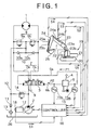
- Fig. 1 shows the hydraulic circuit of a hydraulic control device as the control device of the present invention.
- denoted at 1 is a hydraulic motor as one example of a hydraulic actuator
- 2 is a capacity variable hydraulic pump for supplying working oil to the actuator.
- Denoted at 3 is a control valve for controlling the flow rate and direction of the working oil supplied to the motor 1.
- pilot pressure P1 or P2 derived from a remote control valve 5 acts on either one pilot port of the control valve 3 through a pilot line 6a (or 6b) to switch the control valve 3 from a neutral position (a) to a position (b) or (c).
- Denoted at 9a and 9b are port relief valves.
- Denoted at 10a and 10b are makeup check valves for preventing cavitation in a pipe when the pump flow rate is insufficient to the actuator flow rate consumption, and each valve functions as a brake valve as a whole.
- Denoted at 11 is a back-pressure check valve provided in a return line (return pipeline) 12 in order to ensure back pressure for the makeup, 13 is an oil cooler, and 14 is a main relief valve for keeping the circuit pressure constant.
- valves including the port relief valves 9a, 9b and the main relief valve 14 often collectively mean a pressure control valve.
- Denoted at 15a and 15b are pressure sensors for detecting the pilot pressure of the pilot lines 6a and 6b. Pilot pressure signals PIa, PIb outputted from the pressure sensors 15a, 15b are given to a controller 16.
- the pressure sensors 15a and 15b often collectively mean a pressure sensor 15.
- the controller 16 controls the discharge amount Qp of the hydraulic pump 2 through a regulator (not shown) based on the pilot pressure signal PI outputted from the pressure sensor 15.
- An engine 17 as a driving source of the hydraulic pump 2 has a rotation speed sensor 18 for detecting a speed or a rotation speed of an engine 17.
- Rotation speed signal S1 outputted from the rotation speed sensor 18 is given to the controller 16.
- each sensor mounted on a front attachment 22 of a construction machine 19 is also connected to the controller 16.
- a hydraulic excavator 19 to which the hydraulic control device of this embodiment is applied comprises an upper rotating body 21 rotatably mounted on a lower traveling body 20.
- the front attachment 22 is provided on the front part of the upper rotating body 21.
- the front attachment 22 comprises a boom 23 raised and lowered by the extension and contraction of a boom cylinder 23a, an arm cylinder 24 longitudinally rotated by the expansion and contraction of an arm cylinder 24a, and a bucket 25 longitudinally rotated by the expansion and contraction of a bucket cylinder 25a.
- 23b is a boom cylinder stroke sensor provided on the boom cylinder 23a
- 23c is a boom cylinder pressure sensor
- 24b is an arm cylinder stroke sensor provided on the arm cylinder 24a
- 25b is a bucket cylinder stroke sensor provided on the bucket cylinder 25a.
- Each of the stroke sensors and pressure sensor functions as a detecting means for detecting position and work load of the front attachment 22.
- Signals S2-S4 showing the position of the front attachment 22 and a signal S5 showing the load of the front attachment 22, each of which is outputted from each stroke sensor 23b, 24b, 25b, are also given to the controller 16.
- the internal structure of the controller 16 is shown in Fig. 2.
- the controller 16 calculates, on receipt of the pilot pressure signals PIa, PIb outputted from the pressure sensors 15a, 15b, the relief valve flow rate in an operation amount given by the operating lever 4 by use of a hydraulic driving system emulation model 16a preliminarily stored therein.
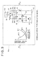
- Fig. 3 shows the emulation model 16a.
- the emulation model 16a shown in the drawing shows a drive system for a rotating system.
- This system mainly comprises a hydraulic pump 30, a hydraulic motor 31, a reduction gear 32 connected to the output shaft of the hydraulic motor 31, a rotation inertial weight 33 connected to the rotating shaft of the reduction gear 32, a control valve 34 for supplying the pressure oil discharged from the hydraulic pump 30 while controlling its flow rate and direction, a main relief valve 35, port relief valves 36a, 36b, check valves 37a, 37b, and a bypass valve 38.
- valves including the port relief valves 36a, 36b and the main relief valve 35 often collectively mean a pressure control valve.
- the control valve 34 comprises a bleed-off valve (B/O) 39, ameter-invalve (M/I) 40, and a meter-out (M/O) 41.
- B/O bleed-off valve
- M/I meter-invalve
- M/O meter-out
- the bleed-off opening (the curve shown by B/O in the figure) is throttled more as the pilot pressure PI becomes larger, as shown by the characteristic of nonlinear control valve opening area shown on the left side of the model.
- a meter-in opening (the curve shown by M/I in the figure) and a meter-out opening (the curve shown by M/O in the drawing) are opened. Consequently, the pressure oil flow rate to be supplied to the hydraulic motor 31 is increased.
- bo bleed-off
- mi meter-in
- mo meter-out
- p pump
- a hydraulic motor
- c check valve
- r port relief valve
- rp main relief valve
- pi pipe part
- 1 upstream side
- 2 downstream side.
- hydraulic pump flow rate Q p is given to the equation (4).
- hydraulic motor capacity q is given to the equation (1).
- the rotating moment of inertia of the upper rotating body 21 is changed according to the position or load of the front attachment 22. Therefore, a control is carried out. Namely, each signal S2-S5 outputted from the boom cylinder stroke sensor 23b, the arm cylinder stroke sensor 24b, the bucket cylinder stroke sensor 25b and the boom cylinder pressure sensor 23c respectively is detected. These signals are loaded to the controller 16. The position and load of the front attachment 22 are calculated based on these signals, and the moment of inertia of JL of the emulation model 16a is changed. According to this, the dynamic characteristic of a hydraulic driving device close to the actual working state can be simulated.
- a numerical integration method for example, the Newmark- ⁇ method is applied to the system of these governing equations (controlling equations), whereby time history response operation is carried out.
- the controller 16 estimates the relief flow rate Qr from the pump pressure measurement value PI by use of the emulation model 16a.
- a hydraulic pump flow control unit 16b determines the pump flow rate according to the following equation by use of the above-mentioned relief flow rate estimation value.
- the cutoff flow rate Qcut obtained by multiplying the relief flow rate estimation value Qr by a gain G is subtracted from Qpc, whereby the pump flow rate Qp is determined.
- the excessive flow rate is released to the tank 42 through the bleed-off valve 39.
- the excessive flow rate Qex is released to the tank 42 through the main relief valve 35 since the bleed-off valve 39 is closed up (refer to Fig. 3) .
- the excessive flow rate is compared between the case with the control of this embodiment and the case without the control.
- the excessive flow rate Qex1 without this control is represented by the following equation (11).
- Qex1 Qpc-Qa
- the cutoff flow rate Qcut is determined, as shown in the equation (10), by multiplying the relief flow rate estimation value Qr by the proportional gain G. Therefore, the cutoff flow rate Qcut is increased and decreased according to the relief flow rate Qr. Since the cutoff flow rate Qcut is increased by this effect when the relief flow rate Qr is large, the improvement in energy efficiency can be enhanced.
- the cutoff flow rate Qcut is determined by using the method of multiplying the relief flow rate by the gain G or a proportional operation in the equation (10) , an integrating operation or differential operation that is a conventional control method may be added. According to this method, steady deviation can be reduced, or the responsiveness can be improved.
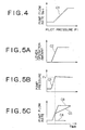
- Figs. 6A-6D and Figs. 7A-7D are graphs for describing the effects by the control of this embodiment.
- Figs. 6A-6D show the operation without the above control shown for comparison.
- the pump pressure rises and exceeds the relief pressure Pr as shown by characteristic C8 of Fig. 6B, whereby the relief valve is operated, and most of the pump flow rate is released to the tank 26 through the relief valve 14 in spite of the supply of the pump flow rate (refer to characteristic C9 of Fig. 6C) . Therefore, the pressure loss of the relief valve 14 is increased to deteriorate the energy efficiency (refer to characteristic C10 of Fig. 6D).
- the pump flow rate is suddenly reduced in the generation of the relief flow rate if the gain G of the equation (10) is large, and the pump pressure is reduced to the relief pressure or less.
- the cutoff flow rate is zero, the pump flow rate is rapidly increased.
- the pump pressure exceeds the relief pressure again to generate the relief flow rate, and the pump flow rate is cut off and rapidly reduced.
- the pump flow rate is controlled to gently increase as shown by characteristic C11 of Fig. 7C. Therefore, the relief flow rate is effectively reduced as shown by characteristic C12 of Fig. 7D, compared with the relief flow rate without the control in Fig. 6D. Accordingly, the relief loss can be reduced to enhance the energy efficiency.
- the controller 16 can be constituted so as to limit the pump flow rate change per unit time to a fixed value or less to prevent the sudden change in the pump flow rate of the capacity variable pump.
- the time change amount of a pump flow instruction value is limited, or a transitional response such as primary delay, moving average or rate limiter is given to the pump flow instruction value. According to this, even if a sudden lever operation is performed, the sudden reduction in pump flow rate can be suppressed although the relief flow rate is rapidly increased, and the hunching can be prevented.
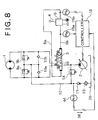
- Fig. 8 shows the second embodiment of the hydraulic control device according to the present invention.
- a back-pressure check valve 11 and an oil cooler 13 are provided on the return pipe 12 communicating with the tank 26.
- a hydraulic cylinder (not shown) is further provided in addition to the hydraulic motor 1 as actuator, the working oil returned through the return pipe 12 or the return-side flow rate is increased by the area-size difference between the head side and rod side of the cylinder in the contracting directional use of the cylinder. Therefore, the pressure loss of the back-pressure check valve 11 and the oil cooler 13 may be increased to raise the pressure in the return pipe 12.
- the arm of the front attachment is operated in a releasing direction, whereby the arm cylinder is operated in the contracting direction.
- the pressure of the return pipe 12 is measured by a pressure sensor 44, and the measured pressure signal S6 is given to the controller 16.
- the pressure signal S6 is made to work as the pressure of the back pressure-side pipe 43 of the relief valve 35 (refer to Fig. 3) , whereby the relief flow rate Qr is estimated.
- the controller 16 may be constituted so as to correct the pump pressure of the hydraulic pump 2 in the emulation model based on the back pressure detected by the pressure sensor 44, and to estimate the relief flow rate based on the corrected pump pressure and the flow characteristic of the relief valve 35.
- a hydraulic motor of a rotating system is described as an example in the above embodiment.
- the actuator may be constituted as either of a winch motor as the driving source of a hoisting system and a traveling motor as the driving source of a traveling system, or the combination thereof.
Landscapes
- Engineering & Computer Science (AREA)
- General Engineering & Computer Science (AREA)
- Mechanical Engineering (AREA)
- Physics & Mathematics (AREA)
- Fluid Mechanics (AREA)
- Mining & Mineral Resources (AREA)
- Civil Engineering (AREA)
- Structural Engineering (AREA)
- Chemical & Material Sciences (AREA)
- Analytical Chemistry (AREA)
- Fluid-Pressure Circuits (AREA)
- Operation Control Of Excavators (AREA)
- Control And Safety Of Cranes (AREA)
Abstract
Description
Claims (11)
- A control device for a working machine comprising:wherein said controller estimates flow rate of the working oil passing through said relief valve from said dynamic emulation model according to an operation amount of said operating means, and controls pump flow rate of said capacity variable hydraulic pump so that flow rate estimation value of said relief value gets close to zero.a capacity variable hydraulic pump for supplying working oil;a controller for controlling a discharge amount of said capacity variable hydraulic pump, said controller having a dynamic emulation model of a hydraulic driving device;a control valve for controlling the working oil discharged from said capacity variable hydraulic pump;a hydraulic actuator adapted to be operated by the working oil from said control valve;an operating means for operating said hydraulic actuator; anda relief valve adapted to be operated when said working oil has a predetermined relief pressure or more,
- The control device for the working machine according to claim 1, wherein said dynamic emulation model has each specification of a pressure control valve including said relief valve, said hydraulic pump, said hydraulic actuator, and said control valve within the model.
- The control device for the working machine according to claim 2, wherein said dynamic emulation model has nonlinear characteristic of said control valve or said pressure control valve.
- The control device for the working machine according to claim 2, further comprising a rotation speed sensor for detecting a rotation speed of an engine of said working machine.
- The control device for the working machine according to claim 4, wherein said controller changes the discharge amount of said hydraulic pump in said emulation model according to the rotation speed detected by said rotation speed sensor.
- The control device for the working machine according to claim 4, further comprising a front attachment provided on said working machine, and a detecting means for detecting position and work load of said front attachment.
- The control device for the working machine according to claim 6, wherein said controller changes moment of inertia of the hydraulic actuator in said emulation model based on the position and work load of the front attachment detected by said detection means.
- The control device for the working machine according to claim 1, wherein said controller limits change amount of the pump flow rate per unit time to a predetermined amount or less so as to prevent a sudden change in the pump flow rate of said capacity variable hydraulic pump.
- The control device for the working machine according to claim 2, further comprising a pressure sensor provided in a return pipeline communicating with an oil tank.
- The control device for the working machine according to claim 9, wherein said controller adjusts a pump pressure of said hydraulic pump in said emulation model based on a back pressure detected by said pressure sensor and estimates the flow rate of said relief valve based on the adjusted pump pressure and a flow characteristic of said relief valve.
- The control device for the working machine according to claim 1, wherein said hydraulic actuator is one of a rotating motor as driving source of a rotating system, a winch motor as driving source of a hoisting system, and a traveling motor as driving source of a traveling system.
Applications Claiming Priority (2)
| Application Number | Priority Date | Filing Date | Title |
|---|---|---|---|
| JP2003145376 | 2003-05-22 | ||
| JP2003145376A JP2004347040A (en) | 2003-05-22 | 2003-05-22 | Controller of working vehicle |
Publications (2)
| Publication Number | Publication Date |
|---|---|
| EP1479920A2 true EP1479920A2 (en) | 2004-11-24 |
| EP1479920A3 EP1479920A3 (en) | 2010-06-09 |
Family
ID=33095471
Family Applications (1)
| Application Number | Title | Priority Date | Filing Date |
|---|---|---|---|
| EP04252912A Withdrawn EP1479920A3 (en) | 2003-05-22 | 2004-05-19 | Control device for working machine |
Country Status (4)
| Country | Link |
|---|---|
| US (1) | US6981371B2 (en) |
| EP (1) | EP1479920A3 (en) |
| JP (1) | JP2004347040A (en) |
| CN (1) | CN1320283C (en) |
Cited By (9)
| Publication number | Priority date | Publication date | Assignee | Title |
|---|---|---|---|---|
| WO2006125873A1 (en) * | 2005-05-27 | 2006-11-30 | Volvo Compact Equipment Sas | Hydraulic circuit for a public works vehicle and vehicle comprising one such circuit |
| EP2505724A4 (en) * | 2009-11-26 | 2013-06-26 | Caterpillar Sarl | Swing hydraulic pressure control device of work machine |
| US8632314B2 (en) | 2009-03-24 | 2014-01-21 | Komatsu Ltd. | Cooling fan driving device and fan rotational speed control method |
| EP2587074A4 (en) * | 2010-06-24 | 2014-04-02 | Volvo Constr Equip Ab | HYDRAULIC PUMP CONTROL SYSTEM FOR CONSTRUCTION MACHINERY |
| EP2600010A4 (en) * | 2010-07-30 | 2015-03-18 | Volvo Constr Equip Ab | Swirl flow control system for construction equipment and method of controlling the same |
| EP2890903A4 (en) * | 2012-08-31 | 2016-04-20 | Caterpillar Inc | Hydraulic control system having over-pressure protection |
| EP1830066A3 (en) * | 2006-03-02 | 2017-07-19 | Kobelco Construction Machinery Co., Ltd. | Hydraulic control apparatus of working machine |
| FR3049995A1 (en) * | 2016-04-12 | 2017-10-13 | Kuhn-Audureau Sa | DEVICE FOR MANAGING THE HYDRAULIC DISTRIBUTION OF A VERIN |
| EP4166793A1 (en) * | 2021-10-15 | 2023-04-19 | Volvo Construction Equipment AB | Hydraulic machine and method of controlling the same |
Families Citing this family (42)
| Publication number | Priority date | Publication date | Assignee | Title |
|---|---|---|---|---|
| US7406982B2 (en) * | 2004-03-25 | 2008-08-05 | Husco International, Inc. | Hydraulic system control method using a differential pressure compensated flow coefficient |
| JP4725345B2 (en) * | 2006-02-08 | 2011-07-13 | 日立建機株式会社 | Hydraulic drive industrial machine |
| WO2009023199A1 (en) * | 2007-08-13 | 2009-02-19 | Clark Equipment Company | Hydraulic control system for a swiveling construction machine |
| CN101981325B (en) * | 2008-03-31 | 2013-11-06 | 株式会社小松制作所 | Rotation drive controlling system for construction machine |
| CN101649849B (en) * | 2008-08-14 | 2012-05-23 | 陈庆桐 | Hydraulic motor brake circuit |
| JP5703587B2 (en) * | 2010-04-14 | 2015-04-22 | コベルコ建機株式会社 | Hybrid work machine |
| WO2012002586A1 (en) * | 2010-06-28 | 2012-01-05 | 볼보 컨스트럭션 이큅먼트 에이비 | Flow control system for a hydraulic pump of construction machinery |
| JP5504423B2 (en) * | 2010-08-27 | 2014-05-28 | 日立建機株式会社 | Hydraulic drive device for hydraulic working machine |
| JP5631799B2 (en) * | 2011-03-31 | 2014-11-26 | 住友建機株式会社 | Construction machinery |
| JP5738674B2 (en) * | 2011-05-25 | 2015-06-24 | コベルコ建機株式会社 | Swivel work machine |
| US8850806B2 (en) | 2011-06-28 | 2014-10-07 | Caterpillar Inc. | Hydraulic control system having swing motor energy recovery |
| US9139982B2 (en) | 2011-06-28 | 2015-09-22 | Caterpillar Inc. | Hydraulic control system having swing energy recovery |
| US9068575B2 (en) | 2011-06-28 | 2015-06-30 | Caterpillar Inc. | Hydraulic control system having swing motor energy recovery |
| US8776511B2 (en) | 2011-06-28 | 2014-07-15 | Caterpillar Inc. | Energy recovery system having accumulator and variable relief |
| US8919113B2 (en) | 2011-06-28 | 2014-12-30 | Caterpillar Inc. | Hydraulic control system having energy recovery kit |
| JP6015157B2 (en) | 2011-07-01 | 2016-10-26 | コベルコ建機株式会社 | Construction machinery |
| JP5586544B2 (en) * | 2011-09-08 | 2014-09-10 | 株式会社クボタ | Working machine |
| JP6003229B2 (en) * | 2012-05-24 | 2016-10-05 | コベルコ建機株式会社 | Boom drive device for construction machinery |
| US9086081B2 (en) | 2012-08-31 | 2015-07-21 | Caterpillar Inc. | Hydraulic control system having swing motor recovery |
| US9328744B2 (en) | 2012-08-31 | 2016-05-03 | Caterpillar Inc. | Hydraulic control system having swing energy recovery |
| US9388829B2 (en) | 2012-08-31 | 2016-07-12 | Caterpillar Inc. | Hydraulic control system having swing motor energy recovery |
| US9187878B2 (en) | 2012-08-31 | 2015-11-17 | Caterpillar Inc. | Hydraulic control system having swing oscillation dampening |
| US9388828B2 (en) | 2012-08-31 | 2016-07-12 | Caterpillar Inc. | Hydraulic control system having swing motor energy recovery |
| US9091286B2 (en) | 2012-08-31 | 2015-07-28 | Caterpillar Inc. | Hydraulic control system having electronic flow limiting |
| JP6054412B2 (en) * | 2012-10-29 | 2016-12-27 | 住友重機械工業株式会社 | Excavator |
| KR102034246B1 (en) * | 2012-10-30 | 2019-10-18 | 스미도모쥬기가이고교 가부시키가이샤 | Shovel |
| WO2014073248A1 (en) * | 2012-11-09 | 2014-05-15 | 住友重機械工業株式会社 | Shovel |
| WO2015019839A1 (en) * | 2013-08-05 | 2015-02-12 | 住友重機械工業株式会社 | Shovel |
| JP6225035B2 (en) * | 2014-01-21 | 2017-11-01 | 川崎重工業株式会社 | Fluid pressure system |
| JP6149819B2 (en) * | 2014-07-30 | 2017-06-21 | コベルコ建機株式会社 | Swivel control device for construction machinery |
| JP6567301B2 (en) * | 2015-03-12 | 2019-08-28 | 住友重機械工業株式会社 | Excavator |
| JP6490458B2 (en) * | 2015-03-13 | 2019-03-27 | 住友重機械工業株式会社 | Excavator |
| CA3068499C (en) * | 2017-06-26 | 2022-03-22 | Suhua LIU | Advance and retreat automatic control method based on hydraulic sensing conversion and advance and retreat automatic control system based on hydraulic sensing conversion |
| EA039359B1 (en) * | 2017-11-06 | 2022-01-18 | Сухуа Лю | Advance and retreat automatic control method based on hydraulic sensing conversion and advance and retreat automatic control system based on hydraulic sensing conversion |
| JP7006350B2 (en) * | 2018-02-15 | 2022-01-24 | コベルコ建機株式会社 | Swivel hydraulic work machine |
| JP7043457B2 (en) | 2019-05-07 | 2022-03-29 | 住友重機械工業株式会社 | Excavator |
| EP4034716B1 (en) * | 2019-09-24 | 2023-08-02 | Clark Equipment Company | System and methods for cycle time management |
| JP7400552B2 (en) | 2020-03-06 | 2023-12-19 | コベルコ建機株式会社 | Hydraulic drive system for working machines |
| RU204361U1 (en) * | 2020-12-18 | 2021-05-21 | Федеральное государственное бюджетное образовательное учреждение высшего образования "Псковский государственный университет" | CONSTANT SPEED HYDRAULIC DRIVE |
| JP7163432B2 (en) * | 2021-02-10 | 2022-10-31 | 住友重機械工業株式会社 | Excavators and systems for excavators |
| JP7615936B2 (en) * | 2021-07-14 | 2025-01-17 | コベルコ建機株式会社 | Construction Machinery |
| US12338604B1 (en) * | 2024-09-30 | 2025-06-24 | Deere & Company | Inertial load dampening hydraulic system with persistent oil conditioning |
Family Cites Families (12)
| Publication number | Priority date | Publication date | Assignee | Title |
|---|---|---|---|---|
| JPS56139316A (en) * | 1980-01-07 | 1981-10-30 | Komatsu Ltd | Power loss reduction controller for oil-pressure type construction machine |
| JPS60215102A (en) * | 1984-04-10 | 1985-10-28 | Tokai Rubber Ind Ltd | Hydraulic source device |
| US5116186A (en) * | 1988-08-02 | 1992-05-26 | Kabushiki Kaisha Komatsu Seisakusho | Apparatus for controlling hydraulic cylinders of a power shovel |
| EP0515639B1 (en) * | 1990-12-15 | 1995-03-08 | Barmag Ag | Hydraulic system |
| JPH09319133A (en) * | 1996-05-28 | 1997-12-12 | Fuji Xerox Co Ltd | Electrostatic charge image developing toner, its production, electrostatic charge image developer and image forming method |
| JP3715063B2 (en) | 1997-03-07 | 2005-11-09 | 日立建機株式会社 | Hydraulic pump cut-off device |
| US5994020A (en) * | 1998-04-13 | 1999-11-30 | Xerox Corporation | Wax containing colorants |
| JP3561667B2 (en) * | 1999-11-18 | 2004-09-02 | 新キャタピラー三菱株式会社 | Control device for hydraulic pump |
| US6282890B1 (en) * | 2000-01-21 | 2001-09-04 | Komatsu Ltd. | Hydraulic circuit for construction machines |
| JP2002038536A (en) | 2000-07-27 | 2002-02-06 | Hitachi Constr Mach Co Ltd | Cutoff control apparatus for construction equipment |
| CN1170068C (en) * | 2002-04-23 | 2004-10-06 | 浙江大学 | Electro-hydraulic digital shunt control system for multi-actuator movement in construction machinery |
| US6852461B2 (en) * | 2002-08-29 | 2005-02-08 | Kabushiki Kaisha Toshiba | Developing agent |
-
2003
- 2003-05-22 JP JP2003145376A patent/JP2004347040A/en not_active Withdrawn
-
2004
- 2004-05-17 US US10/846,557 patent/US6981371B2/en not_active Expired - Fee Related
- 2004-05-19 EP EP04252912A patent/EP1479920A3/en not_active Withdrawn
- 2004-05-22 CN CNB2004100631679A patent/CN1320283C/en not_active Expired - Fee Related
Cited By (14)
| Publication number | Priority date | Publication date | Assignee | Title |
|---|---|---|---|---|
| WO2006125873A1 (en) * | 2005-05-27 | 2006-11-30 | Volvo Compact Equipment Sas | Hydraulic circuit for a public works vehicle and vehicle comprising one such circuit |
| US7856819B2 (en) | 2005-05-27 | 2010-12-28 | Volvo Compact Equipment Sas | Hydraulic circuit for a public works vehicle and vehicle comprising one such circuit |
| EP1830066A3 (en) * | 2006-03-02 | 2017-07-19 | Kobelco Construction Machinery Co., Ltd. | Hydraulic control apparatus of working machine |
| EP2412948A4 (en) * | 2009-03-24 | 2017-05-17 | Komatsu, Ltd. | Cooling fan driving device and fan rotation number control method |
| US8632314B2 (en) | 2009-03-24 | 2014-01-21 | Komatsu Ltd. | Cooling fan driving device and fan rotational speed control method |
| US9109346B2 (en) | 2009-11-26 | 2015-08-18 | Caterpillar Sarl | Hydraulic swing-controlling apparatus of work machine |
| EP2505724A4 (en) * | 2009-11-26 | 2013-06-26 | Caterpillar Sarl | Swing hydraulic pressure control device of work machine |
| EP2587074A4 (en) * | 2010-06-24 | 2014-04-02 | Volvo Constr Equip Ab | HYDRAULIC PUMP CONTROL SYSTEM FOR CONSTRUCTION MACHINERY |
| US9194382B2 (en) | 2010-06-24 | 2015-11-24 | Volvo Contruction Equipment Ab | Hydraulic pump control system for construction machinery |
| EP2600010A4 (en) * | 2010-07-30 | 2015-03-18 | Volvo Constr Equip Ab | Swirl flow control system for construction equipment and method of controlling the same |
| EP2890903A4 (en) * | 2012-08-31 | 2016-04-20 | Caterpillar Inc | Hydraulic control system having over-pressure protection |
| FR3049995A1 (en) * | 2016-04-12 | 2017-10-13 | Kuhn-Audureau Sa | DEVICE FOR MANAGING THE HYDRAULIC DISTRIBUTION OF A VERIN |
| EP4166793A1 (en) * | 2021-10-15 | 2023-04-19 | Volvo Construction Equipment AB | Hydraulic machine and method of controlling the same |
| US12281661B2 (en) | 2021-10-15 | 2025-04-22 | Volvo Construction Equipment Ab | Hydraulic machine and method of controlling the same |
Also Published As
| Publication number | Publication date |
|---|---|
| EP1479920A3 (en) | 2010-06-09 |
| CN1573126A (en) | 2005-02-02 |
| CN1320283C (en) | 2007-06-06 |
| US20040231326A1 (en) | 2004-11-25 |
| US6981371B2 (en) | 2006-01-03 |
| JP2004347040A (en) | 2004-12-09 |
Similar Documents
| Publication | Publication Date | Title |
|---|---|---|
| US6981371B2 (en) | Control device for working machine | |
| US7296404B2 (en) | Apparatus for controlling deceleration of hydraulically powered equipment | |
| US8726647B2 (en) | Hydraulic control system having cylinder stall strategy | |
| US8844280B2 (en) | Hydraulic control system having cylinder flow correction | |
| US10393260B2 (en) | Hydraulic control apparatus and method | |
| US20170184139A1 (en) | Method of controlling velocity of a hydraulic actuator in over-center linkage systems | |
| EP3779210B1 (en) | Construction machine | |
| US7210396B2 (en) | Valve having a hysteretic filtered actuation command | |
| JPWO2019186841A1 (en) | Hydraulic drive for construction machinery | |
| CN103403364A (en) | Hydraulic Control System with Cylinder Stall Strategy | |
| US20090145120A1 (en) | Method and circuit arrangement of the supply of pressue medium to at least two hydraulic consumers | |
| JP6226851B2 (en) | Hydraulic control device for work machine | |
| JP3925416B2 (en) | Hydraulic control device for work machine | |
| CN101184923A (en) | Hydraulic system with back pressure compensator | |
| JP3536710B2 (en) | Actuator control circuit of hydraulic working machine | |
| EP3591124B1 (en) | Hydraulic driving apparatus of work machine | |
| US20140032057A1 (en) | Feedforward control system | |
| JP4973047B2 (en) | Hydraulic control circuit for work machines | |
| JP4003644B2 (en) | Hydraulic control device for work machine | |
| US12325978B2 (en) | Work machine | |
| US12392106B2 (en) | Construction machine | |
| KR940002512A (en) | Road sensing hydraulic automatic control device of construction machine | |
| JP2018028357A (en) | Hydraulic system for construction machine | |
| KR20250049552A (en) | work machine | |
| JP2007032788A (en) | Fluid pressure controller for traveling working machine and fluid pressure control method for traveling working machine |
Legal Events
| Date | Code | Title | Description |
|---|---|---|---|
| PUAI | Public reference made under article 153(3) epc to a published international application that has entered the european phase |
Free format text: ORIGINAL CODE: 0009012 |
|
| AK | Designated contracting states |
Kind code of ref document: A2 Designated state(s): AT BE BG CH CY CZ DE DK EE ES FI FR GB GR HU IE IT LI LU MC NL PL PT RO SE SI SK TR |
|
| AX | Request for extension of the european patent |
Extension state: AL HR LT LV MK |
|
| PUAL | Search report despatched |
Free format text: ORIGINAL CODE: 0009013 |
|
| AK | Designated contracting states |
Kind code of ref document: A3 Designated state(s): AT BE BG CH CY CZ DE DK EE ES FI FR GB GR HU IE IT LI LU MC NL PL PT RO SE SI SK TR |
|
| AX | Request for extension of the european patent |
Extension state: AL HR LT LV MK |
|
| AKY | No designation fees paid | ||
| REG | Reference to a national code |
Ref country code: DE Ref legal event code: 8566 |
|
| STAA | Information on the status of an ep patent application or granted ep patent |
Free format text: STATUS: THE APPLICATION IS DEEMED TO BE WITHDRAWN |
|
| 18D | Application deemed to be withdrawn |
Effective date: 20101210 |