図面を参照しながら本発明の実施例について説明する。
Embodiments of the present invention will be described with reference to the drawings.
図1は、本発明の実施例に係る油圧ショベルを示す側面図である。油圧ショベルの下部走行体1には、旋回機構2を介して上部旋回体3が搭載されている。上部旋回体3には、ブーム4が取り付けられている。ブーム4の先端にはアーム5が取り付けられ、アーム5の先端にはバケット6が取り付けられている。ブーム4、アーム5、及びバケット6は、アタッチメントを構成し、油圧シリンダであるブームシリンダ7、アームシリンダ8、及びバケットシリンダ9によりそれぞれ油圧駆動される。上部旋回体3には、キャビン10が設けられ、且つエンジン等の動力源が搭載される。
FIG. 1 is a side view showing a hydraulic excavator according to an embodiment of the present invention. An upper swing body 3 is mounted on the lower traveling body 1 of the hydraulic excavator via a swing mechanism 2. A boom 4 is attached to the upper swing body 3. An arm 5 is attached to the tip of the boom 4, and a bucket 6 is attached to the tip of the arm 5. The boom 4, the arm 5, and the bucket 6 constitute an attachment, and are hydraulically driven by a boom cylinder 7, an arm cylinder 8, and a bucket cylinder 9, which are hydraulic cylinders. The upper swing body 3 is provided with a cabin 10 and is mounted with a power source such as an engine.
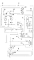
図2は、図1の油圧ショベルの駆動系の構成を示すブロック図である。図2において、機械的動力系は二重線、高圧油圧ラインは太実線、パイロットラインは破線、電気駆動・制御系は細実線でそれぞれ示されている。
FIG. 2 is a block diagram showing the configuration of the drive system of the hydraulic excavator shown in FIG. In FIG. 2, the mechanical power system is indicated by a double line, the high-pressure hydraulic line is indicated by a thick solid line, the pilot line is indicated by a broken line, and the electric drive / control system is indicated by a thin solid line.
機械式駆動部としてのエンジン11の出力軸には、可変容量型油圧ポンプとしてのメインポンプ14、及び、固定容量型油圧ポンプとしてのパイロットポンプ15が接続されている。メインポンプ14には、高圧油圧ライン16及び第1放圧部44を介してコントロールバルブ17が接続されている。また、パイロットポンプ15には、パイロットライン25を介して操作装置26が接続されている。
A main pump 14 as a variable displacement hydraulic pump and a pilot pump 15 as a fixed displacement hydraulic pump are connected to the output shaft of the engine 11 as a mechanical drive unit. A control valve 17 is connected to the main pump 14 via a high-pressure hydraulic line 16 and a first pressure release part 44. An operation device 26 is connected to the pilot pump 15 via a pilot line 25.
コントロールバルブ17は、油圧ショベルにおける油圧系の制御を行う装置である。走行用油圧モータ1A(右用)、走行用油圧モータ1B(左用)、ブームシリンダ7、アームシリンダ8、バケットシリンダ9、旋回油圧モータ21等の油圧アクチュエータは、高圧油圧ラインを介してコントロールバルブ17に接続されている。
The control valve 17 is a device that controls the hydraulic system in the hydraulic excavator. The hydraulic actuators such as the traveling hydraulic motor 1A (for right), the traveling hydraulic motor 1B (for left), the boom cylinder 7, the arm cylinder 8, the bucket cylinder 9 and the swing hydraulic motor 21 are connected to the control valve 17 via a high pressure hydraulic line. It is connected to the.
操作装置26は、レバー26A、レバー26B、及びペダル26Cを含む。レバー26A、レバー26B、及びペダル26Cは、油圧ライン27及び28を介して、コントロールバルブ17及び圧力センサ29にそれぞれ接続されている。
The operating device 26 includes a lever 26A, a lever 26B, and a pedal 26C. The lever 26A, the lever 26B, and the pedal 26C are connected to the control valve 17 and the pressure sensor 29 via hydraulic lines 27 and 28, respectively.
圧力センサ29は、操作装置26を用いた操作者の操作内容を検出するためのセンサである。圧力センサ29は、例えば、油圧アクチュエータのそれぞれに対応する操作装置26のレバー又はペダルの操作方向及び操作量を圧力の形で検出し、検出した値をコントローラ30に対して出力する。なお、操作装置26の操作内容は、圧力センサ以外の他のセンサを用いて検出されてもよい。
The pressure sensor 29 is a sensor for detecting the operation content of the operator using the operation device 26. For example, the pressure sensor 29 detects the operation direction and the operation amount of the lever or pedal of the operation device 26 corresponding to each of the hydraulic actuators in the form of pressure, and outputs the detected value to the controller 30. Note that the operation content of the operation device 26 may be detected using a sensor other than the pressure sensor.
コントローラ30は、油圧ショベルの駆動制御を行う主制御部としてのコントローラである。コントローラ30は、CPU(Central Processing Unit)及び内部メモリを含む演算処理装置で構成され、内部メモリに格納された駆動制御用のプログラムをCPUに実行させて油圧ショベルの駆動制御を行う。
The controller 30 is a controller as a main control unit that performs drive control of the hydraulic excavator. The controller 30 includes a CPU (Central Processing Unit) and an arithmetic processing unit including an internal memory. The controller 30 controls the hydraulic excavator by causing the CPU to execute a drive control program stored in the internal memory.
圧力センサS1は、メインポンプ14の吐出圧を検出するセンサであり、検出した値をコントローラ30に対して出力する。
The pressure sensor S1 is a sensor that detects the discharge pressure of the main pump 14, and outputs the detected value to the controller 30.
圧力センサS2Lは、旋回油圧モータ21の第1ポート側の作動油の圧力を検出するセンサであり、検出した値をコントローラ30に対して出力する。
The pressure sensor S2L is a sensor that detects the pressure of the hydraulic oil on the first port side of the swing hydraulic motor 21, and outputs the detected value to the controller 30.
圧力センサS2Rは、旋回油圧モータ21の第2ポート側の作動油の圧力を検出するセンサであり、検出した値をコントローラ30に対して出力する。
The pressure sensor S <b> 2 </ b> R is a sensor that detects the pressure of hydraulic oil on the second port side of the swing hydraulic motor 21, and outputs the detected value to the controller 30.
圧力センサS3は、アキュムレータ部41の作動油の圧力(以下、「アキュムレータ圧力」とする。)を検出するセンサであり、検出した値をコントローラ30に対して出力する。
The pressure sensor S3 is a sensor that detects the pressure of the hydraulic oil in the accumulator unit 41 (hereinafter referred to as “accumulator pressure”), and outputs the detected value to the controller 30.
圧力センサS4は、ブームシリンダ7のボトム側油室の作動油の圧力を検出するセンサであり、検出した値をコントローラ30に対して出力する。
The pressure sensor S4 is a sensor that detects the pressure of the hydraulic oil in the bottom side oil chamber of the boom cylinder 7, and outputs the detected value to the controller 30.
アキュムレータ部41は、油圧回路内の作動油を蓄積し、必要に応じてその蓄積した作動油を放出する油圧回路要素である。
The accumulator unit 41 is a hydraulic circuit element that accumulates the hydraulic oil in the hydraulic circuit and releases the accumulated hydraulic oil as necessary.
第1蓄圧部42は、旋回油圧モータ21とアキュムレータ部41との間の作動油の流れを制御する油圧回路要素である。
The first pressure accumulating unit 42 is a hydraulic circuit element that controls the flow of hydraulic oil between the swing hydraulic motor 21 and the accumulator unit 41.
第2蓄圧部43は、コントロールバルブ17とアキュムレータ部41との間の作動油の流れを制御する油圧回路要素である。
The second pressure accumulating unit 43 is a hydraulic circuit element that controls the flow of hydraulic oil between the control valve 17 and the accumulator unit 41.
第1放圧部44は、メインポンプ14とコントロールバルブ17とアキュムレータ部41との間の作動油の流れを制御する油圧回路要素である。
The first pressure release part 44 is a hydraulic circuit element that controls the flow of hydraulic oil among the main pump 14, the control valve 17, and the accumulator part 41.
第2放圧部45は、メインポンプ14とタンクとアキュムレータ部41との間の作動油の流れを制御する油圧回路要素である。
The second pressure release unit 45 is a hydraulic circuit element that controls the flow of hydraulic oil between the main pump 14, the tank, and the accumulator unit 41.
なお、アキュムレータ部41、第1蓄圧部42、第2蓄圧部43、第1放圧部44、及び第2放圧部45についてはその詳細を後述する。
The accumulator part 41, the first pressure accumulating part 42, the second pressure accumulating part 43, the first pressure releasing part 44, and the second pressure releasing part 45 will be described in detail later.
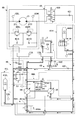
次に、図3を参照しながら、図1の油圧ショベルに搭載されるアキュムレータ部41の蓄圧及び放圧について説明する。なお、図3は、図1の油圧ショベルに搭載される油圧回路の要部構成例を示す。
Next, with reference to FIG. 3, accumulation and release of pressure in the accumulator unit 41 mounted on the hydraulic excavator in FIG. 1 will be described. FIG. 3 shows a configuration example of a main part of a hydraulic circuit mounted on the hydraulic excavator shown in FIG.
図3に示す油圧回路は、主に、旋回制御部40、アキュムレータ部41、第1蓄圧部42、第2蓄圧部43、第1放圧部44、及び第2放圧部45を含む。
The hydraulic circuit shown in FIG. 3 mainly includes a turning control unit 40, an accumulator unit 41, a first pressure accumulating unit 42, a second pressure accumulating unit 43, a first pressure releasing unit 44, and a second pressure releasing unit 45.
旋回制御部40は、主に、旋回油圧モータ21、リリーフ弁400L、400R、及び逆止弁401L、401Rを含む。
The turning control unit 40 mainly includes a turning hydraulic motor 21, relief valves 400L and 400R, and check valves 401L and 401R.
リリーフ弁400Lは、旋回油圧モータ21の第1ポート21L側の作動油の圧力が所定の旋回リリーフ圧を超えるのを防止するための弁である。具体的には、第1ポート21L側の作動油の圧力が所定の旋回リリーフ圧に達した場合に、第1ポート21L側の作動油をタンクに排出する。
The relief valve 400L is a valve for preventing the hydraulic oil pressure on the first port 21L side of the swing hydraulic motor 21 from exceeding a predetermined swing relief pressure. Specifically, when the pressure of the hydraulic oil on the first port 21L side reaches a predetermined turning relief pressure, the hydraulic oil on the first port 21L side is discharged to the tank.
同様に、リリーフ弁400Rは、旋回油圧モータ21の第2ポート21R側の作動油の圧力が所定の旋回リリーフ圧を超えるのを防止するための弁である。具体的には、第2ポート21R側の作動油の圧力が所定の旋回リリーフ圧に達した場合に、第2ポート21R側の作動油をタンクに排出する。
Similarly, the relief valve 400R is a valve for preventing the hydraulic oil pressure on the second port 21R side of the swing hydraulic motor 21 from exceeding a predetermined swing relief pressure. Specifically, when the pressure of the hydraulic oil on the second port 21R side reaches a predetermined turning relief pressure, the hydraulic oil on the second port 21R side is discharged to the tank.
逆止弁401Lは、第1ポート21L側の作動油の圧力がタンク圧未満になるのを防止するための弁である。具体的には、第1ポート21L側の作動油の圧力がタンク圧まで低下した場合に、タンク内の作動油を第1ポート21L側に供給する。
The check valve 401L is a valve for preventing the hydraulic oil pressure on the first port 21L side from becoming less than the tank pressure. Specifically, when the pressure of the hydraulic oil on the first port 21L side decreases to the tank pressure, the hydraulic oil in the tank is supplied to the first port 21L side.
同様に、逆止弁401Rは、第2ポート21R側の作動油の圧力がタンク圧未満になるのを防止するための弁である。具体的には、第2ポート21R側の作動油の圧力がタンク圧まで低下した場合に、タンク内の作動油を第2ポート21R側に供給する。
Similarly, the check valve 401R is a valve for preventing the hydraulic oil pressure on the second port 21R side from becoming less than the tank pressure. Specifically, when the pressure of the hydraulic oil on the second port 21R side decreases to the tank pressure, the hydraulic oil in the tank is supplied to the second port 21R side.
アキュムレータ部41は、油圧回路内の作動油を蓄積し、必要に応じてその蓄積した作動油を放出する油圧回路要素である。具体的には、アキュムレータ部41は、旋回減速中に旋回油圧モータ21の制動側(吐出側)の作動油を蓄積する。また、アキュムレータ部41は、ブーム下げ操作中にブームシリンダ7が排出する作動油を蓄積する。そして、アキュムレータ部41は、油圧アクチュエータを操作する際に、その蓄積した作動油をメインポンプ14の上流側(吸い込み側)又は下流側(吐出側)に放出する。
The accumulator unit 41 is a hydraulic circuit element that accumulates the hydraulic oil in the hydraulic circuit and releases the accumulated hydraulic oil as necessary. Specifically, the accumulator unit 41 accumulates hydraulic oil on the braking side (discharge side) of the turning hydraulic motor 21 during turning deceleration. Moreover, the accumulator part 41 accumulate | stores the hydraulic oil which the boom cylinder 7 discharges during boom lowering operation. Then, when operating the hydraulic actuator, the accumulator unit 41 releases the accumulated hydraulic fluid to the upstream side (suction side) or the downstream side (discharge side) of the main pump 14.
本実施例では、アキュムレータ部41は、主に、アキュムレータ410を含む。アキュムレータ410は、油圧回路内の作動油を蓄積し、必要に応じてその蓄積した作動油を放出する装置である。本実施例では、アキュムレータ410は、バネの復元力を利用するバネ型アキュムレータである。
In the present embodiment, the accumulator unit 41 mainly includes an accumulator 410. The accumulator 410 is a device that accumulates the hydraulic oil in the hydraulic circuit and releases the accumulated hydraulic oil as necessary. In this embodiment, the accumulator 410 is a spring type accumulator that uses the restoring force of a spring.
第1蓄圧部42は、旋回制御部40(旋回油圧モータ21)とアキュムレータ部41との間の作動油の流れを制御する油圧回路要素である。本実施例では、第1蓄圧部42は、主に、第1切換弁420及び第1逆止弁421を含む。
The first pressure accumulating unit 42 is a hydraulic circuit element that controls the flow of hydraulic oil between the turning control unit 40 (the turning hydraulic motor 21) and the accumulator unit 41. In the present embodiment, the first pressure accumulator 42 mainly includes a first switching valve 420 and a first check valve 421.
第1切換弁420は、アキュムレータ部41の蓄圧(回生)動作の際に、旋回制御部40からアキュムレータ部41への作動油の流れを制御する弁である。本実施例では、第1切換弁420は、3ポート3位置の切換弁であり、コントローラ30からの制御信号に応じて弁位置を切り換える電磁弁が用いられる。また、パイロット圧を用いた比例弁が用いられてもよい。具体的には、第1切換弁420は、第1位置、第2位置、及び第3位置を弁位置として有する。なお、図中の括弧内の数字は、弁位置の番号を表す。他の切換弁についても同様である。
The first switching valve 420 is a valve that controls the flow of hydraulic oil from the turning control unit 40 to the accumulator unit 41 during the pressure accumulation (regeneration) operation of the accumulator unit 41. In the present embodiment, the first switching valve 420 is a three-port three-position switching valve, and an electromagnetic valve that switches the valve position in accordance with a control signal from the controller 30 is used. Further, a proportional valve using a pilot pressure may be used. Specifically, the first switching valve 420 has a first position, a second position, and a third position as valve positions. The numbers in parentheses in the figure represent the valve position numbers. The same applies to other switching valves.
第1位置は、第1ポート21Lとアキュムレータ部41とを連通させる弁位置である。また、第2位置は、旋回制御部40とアキュムレータ部41との間の連通を遮断する弁位置である。また、第3位置は、第2ポート21Rとアキュムレータ部41とを連通させる弁位置である。
The first position is a valve position for communicating the first port 21L and the accumulator unit 41. The second position is a valve position that blocks communication between the turning control unit 40 and the accumulator unit 41. The third position is a valve position for communicating the second port 21R and the accumulator unit 41.
第1逆止弁421は、アキュムレータ部41から旋回制御部40に作動油が流れるのを防止する弁である。
The first check valve 421 is a valve that prevents hydraulic oil from flowing from the accumulator unit 41 to the turning control unit 40.
第2蓄圧部43は、コントロールバルブ17とアキュムレータ部41との間の作動油の流れを制御する油圧回路要素である。本実施例では、第2蓄圧部43は、ブームシリンダ用流量制御弁17Bとタンクとアキュムレータ部41との間に配置され、主に、第2切換弁430及び第2逆止弁431を含む。なお、ブームシリンダ用流量制御弁17Bは、アームシリンダ用流量制御弁等の1又は複数の他の流量制御弁であってもよい。
The second pressure accumulating unit 43 is a hydraulic circuit element that controls the flow of hydraulic oil between the control valve 17 and the accumulator unit 41. In the present embodiment, the second pressure accumulating portion 43 is disposed between the boom cylinder flow control valve 17B, the tank, and the accumulator portion 41, and mainly includes a second switching valve 430 and a second check valve 431. The boom cylinder flow control valve 17B may be one or more other flow control valves such as an arm cylinder flow control valve.
第2切換弁430は、アキュムレータ部41の蓄圧(回生)動作の際に、油圧アクチュエータからアキュムレータ部41への作動油の流れを制御する弁である。本実施例では、第2切換弁430は、3ポート2位置の切換弁であり、コントローラ30からの制御信号に応じて弁位置を切り換える電磁弁が用いられる。また、パイロット圧を用いた比例弁が用いられてもよい。具体的には、第2切換弁430は、第1位置及び第2位置を弁位置として有する。第1位置は、ブームシリンダ用流量制御弁17Bの排出ポートとタンクとを連通させ、且つ、ブームシリンダ用流量制御弁17Bの排出ポートとアキュムレータ部41との間の連通を遮断する弁位置である。また、第2位置は、ブームシリンダ用流量制御弁17Bの排出ポートとアキュムレータ部41とを連通させ、且つ、ブームシリンダ用流量制御弁17Bの排出ポートとタンクとの間の連通を遮断する弁位置である。
The second switching valve 430 is a valve that controls the flow of hydraulic oil from the hydraulic actuator to the accumulator unit 41 during the pressure accumulation (regeneration) operation of the accumulator unit 41. In this embodiment, the second switching valve 430 is a 3-port 2-position switching valve, and an electromagnetic valve that switches the valve position in accordance with a control signal from the controller 30 is used. Further, a proportional valve using a pilot pressure may be used. Specifically, the second switching valve 430 has a first position and a second position as valve positions. The first position is a valve position that connects the discharge port of the boom cylinder flow control valve 17B and the tank, and blocks communication between the discharge port of the boom cylinder flow control valve 17B and the accumulator unit 41. . Further, the second position is a valve position where the discharge port of the boom cylinder flow control valve 17B and the accumulator unit 41 are communicated and the communication between the discharge port of the boom cylinder flow control valve 17B and the tank is cut off. It is.
第2逆止弁431は、アキュムレータ部41から第2切換弁430に作動油が流れるのを防止する弁である。
The second check valve 431 is a valve that prevents hydraulic oil from flowing from the accumulator unit 41 to the second switching valve 430.
第1放圧部44は、メインポンプ14とコントロールバルブ17とアキュムレータ部41との間の作動油の流れを制御する油圧回路要素である。本実施例では、第1放圧部44は、主に、第3切換弁440及び第3逆止弁441を含む。
The first pressure release part 44 is a hydraulic circuit element that controls the flow of hydraulic oil among the main pump 14, the control valve 17, and the accumulator part 41. In the present embodiment, the first pressure release unit 44 mainly includes a third switching valve 440 and a third check valve 441.
第3切換弁440は、アキュムレータ部41の放圧(力行)動作の際に、アキュムレータ部41からメインポンプ14の下流側の合流点への作動油の流れを制御する弁である。本実施例では、第3切換弁440は、2ポート2位置の切換弁であり、コントローラ30からの制御信号に応じて弁位置を切り換える電磁弁が用いられる。また、パイロット圧を用いた比例弁が用いられてもよい。具体的には、第3切換弁440は、第1位置及び第2位置を弁位置として有する。第1位置は、メインポンプ14の下流側の合流点とアキュムレータ部41との間の連通を遮断する弁位置である。また、第2位置は、メインポンプ14の下流側の合流点とアキュムレータ部41とを連通させる弁位置である。
The third switching valve 440 is a valve that controls the flow of hydraulic oil from the accumulator unit 41 to the junction point on the downstream side of the main pump 14 during the pressure release (powering) operation of the accumulator unit 41. In the present embodiment, the third switching valve 440 is a 2-port 2-position switching valve, and an electromagnetic valve that switches the valve position in accordance with a control signal from the controller 30 is used. Further, a proportional valve using a pilot pressure may be used. Specifically, the third switching valve 440 has a first position and a second position as valve positions. The first position is a valve position that blocks communication between the junction on the downstream side of the main pump 14 and the accumulator unit 41. The second position is a valve position at which the confluence point on the downstream side of the main pump 14 communicates with the accumulator unit 41.
第3逆止弁441は、メインポンプ14からアキュムレータ部41に作動油が流れるのを防止する弁である。
The third check valve 441 is a valve that prevents hydraulic oil from flowing from the main pump 14 to the accumulator unit 41.
第2放圧部45は、タンクとメインポンプ14とアキュムレータ部41との間の作動油の流れを制御する油圧回路要素である。本実施例では、第2放圧部45は、主に、第4切換弁450を含む。
The second pressure release unit 45 is a hydraulic circuit element that controls the flow of hydraulic oil between the tank, the main pump 14 and the accumulator unit 41. In the present embodiment, the second pressure release part 45 mainly includes a fourth switching valve 450.
第4切換弁450は、アキュムレータ部41の放圧(力行)動作の際に、アキュムレータ部41からメインポンプ14の上流側の合流点への作動油の流れを制御する弁である。本実施例では、第4切換弁450は、3ポート2位置の切換弁であり、コントローラ30からの制御信号に応じて弁位置を切り換える電磁弁が用いられる。また、パイロット圧を用いた比例弁が用いられてもよい。具体的には、第4切換弁450は、第1位置及び第2位置を弁位置として有する。第1位置は、メインポンプ14とタンクとを連通させ、且つ、メインポンプ14とアキュムレータ部41との間の連通を遮断する弁位置である。また、第2位置は、メインポンプ14とタンクとの間の連通を遮断し、且つ、メインポンプ14とアキュムレータ部41とを連通させる弁位置である。
The fourth switching valve 450 is a valve that controls the flow of the hydraulic oil from the accumulator unit 41 to the merging point on the upstream side of the main pump 14 during the pressure release (powering) operation of the accumulator unit 41. In the present embodiment, the fourth switching valve 450 is a three-port two-position switching valve, and an electromagnetic valve that switches the valve position in accordance with a control signal from the controller 30 is used. Further, a proportional valve using a pilot pressure may be used. Specifically, the fourth switching valve 450 has a first position and a second position as valve positions. The first position is a valve position that allows the main pump 14 and the tank to communicate with each other and blocks communication between the main pump 14 and the accumulator unit 41. The second position is a valve position that blocks communication between the main pump 14 and the tank and allows the main pump 14 and the accumulator unit 41 to communicate with each other.
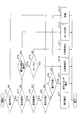
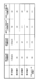
ここで、図4及び図5を参照しながら、コントローラ30がアキュムレータ部41の蓄圧及び放圧を制御する処理(以下、「蓄圧・放圧処理」とする。)について説明する。なお、図4は、蓄圧・放圧処理の流れを示すフローチャートであり、コントローラ30は、所定周期で繰り返しこの蓄圧・放圧処理を実行する。また、図5は、図3の油圧回路の状態と各切換弁の状態との対応関係を示す対応表である。
Here, a process in which the controller 30 controls the pressure accumulation and pressure release of the accumulator unit 41 (hereinafter referred to as “accumulation / pressure release process”) will be described with reference to FIGS. 4 and 5. FIG. 4 is a flowchart showing the flow of the pressure accumulation / release pressure process, and the controller 30 repeatedly executes this pressure accumulation / release pressure process at a predetermined cycle. FIG. 5 is a correspondence table showing the correspondence between the state of the hydraulic circuit in FIG. 3 and the state of each switching valve.
最初に、コントローラ30は、油圧ショベルの状態を検出するための各種センサの出力に基づいて、油圧アクチュエータの操作が行われたか否かを判定する(ステップST1)。本実施例では、コントローラ30は、圧力センサ29の出力に基づいて油圧アクチュエータの操作が行われたか否かを判定する。
First, the controller 30 determines whether or not the hydraulic actuator has been operated based on the outputs of various sensors for detecting the state of the hydraulic excavator (step ST1). In this embodiment, the controller 30 determines whether or not the hydraulic actuator has been operated based on the output of the pressure sensor 29.
油圧アクチュエータの操作が行われたと判定すると(ステップST1のYES)、コントローラ30は、その操作が回生操作又は力行操作の何れであるかを判定する(ステップST2)。本実施例では、コントローラ30は、圧力センサ29の出力に基づいて、旋回減速操作、ブーム下げ操作等の回生操作が行われたか、或いは、旋回加速操作、ブーム上げ操作等の力行操作が行われたかを判定する。
When it is determined that the operation of the hydraulic actuator has been performed (YES in step ST1), the controller 30 determines whether the operation is a regenerative operation or a power running operation (step ST2). In this embodiment, the controller 30 performs a regenerative operation such as a turning deceleration operation or a boom lowering operation based on the output of the pressure sensor 29, or a power running operation such as a turning acceleration operation or a boom raising operation. It is determined.
回生操作が行われたと判定すると(ステップST2のYES)、コントローラ30は、その回生操作が旋回減速操作であるか或いはそれ以外の回生操作であるかを判定する(ステップST3)。
If it is determined that the regenerative operation has been performed (YES in step ST2), the controller 30 determines whether the regenerative operation is a turning deceleration operation or another regenerative operation (step ST3).
そして、回生操作が旋回減速操作であると判定すると(ステップST3のYES)、コントローラ30は、アキュムレータ部41が蓄圧可能な状態にあるか否かを判定する(ステップST4)。本実施例では、コントローラ30は、圧力センサS2L又は圧力センサS2Rが出力する旋回油圧モータ21の制動側(吐出側)の圧力Psoと、圧力センサS3が出力するアキュムレータ圧力Paとに基づいてアキュムレータ部41が蓄圧可能な状態にあるか否かを判定する。具体的には、コントローラ30は、圧力Psoがアキュムレータ圧力Paを上回る場合にアキュムレータ部41が蓄圧可能な状態にあると判定し、圧力Psoがアキュムレータ圧力Pa以下の場合に、アキュムレータ部41が蓄圧可能な状態にないと判定する。
If it is determined that the regenerative operation is a turning deceleration operation (YES in step ST3), the controller 30 determines whether or not the accumulator unit 41 is in a state where pressure accumulation is possible (step ST4). In the present embodiment, the controller 30 includes an accumulator unit based on the braking side (discharge side) pressure Pso of the swing hydraulic motor 21 output from the pressure sensor S2L or the pressure sensor S2R and the accumulator pressure Pa output from the pressure sensor S3. It is determined whether 41 is in a state capable of accumulating pressure. Specifically, the controller 30 determines that the accumulator unit 41 is in a state where pressure can be accumulated when the pressure Pso exceeds the accumulator pressure Pa, and the accumulator unit 41 can accumulate pressure when the pressure Pso is equal to or less than the accumulator pressure Pa. It is determined that there is no state.
そして、アキュムレータ部41が蓄圧可能な状態にあると判定すると(ステップST4のYES)、コントローラ30は、油圧回路の状態を「旋回蓄圧」の状態にする(ステップST5)。
And when it determines with the accumulator part 41 being in the state which can be pressure-accumulated (YES of step ST4), the controller 30 will make the state of a hydraulic circuit the state of a "turning pressure accumulation" (step ST5).
図5に示すように、「旋回蓄圧」の状態では、コントローラ30は、第1切換弁420を第1位置又は第3位置とし、第1蓄圧部42を通じて旋回制御部40とアキュムレータ部41とを連通させる。また、コントローラ30は、第2切換弁430を第1位置とし、ブームシリンダ用流量制御弁17Bの排出ポートとタンクとを連通させ、且つ、ブームシリンダ用流量制御弁17Bの排出ポートとアキュムレータ部41との間の連通を遮断する。また、コントローラ30は、第3切換弁440を第1位置とし、メインポンプ14の下流側の合流点とアキュムレータ部41との間の連通を遮断する。さらに、コントローラ30は、第4切換弁450を第1位置とし、メインポンプ14とタンクとを連通させ、メインポンプ14とアキュムレータ部41との間の連通を遮断する。
As shown in FIG. 5, in the “turning pressure accumulation” state, the controller 30 sets the first switching valve 420 to the first position or the third position, and connects the turning control part 40 and the accumulator part 41 through the first pressure accumulation part 42. Communicate. Further, the controller 30 places the second switching valve 430 in the first position, communicates the discharge port of the boom cylinder flow control valve 17B and the tank, and connects the discharge port of the boom cylinder flow control valve 17B to the accumulator unit 41. Block communication with In addition, the controller 30 sets the third switching valve 440 to the first position, and blocks communication between the junction on the downstream side of the main pump 14 and the accumulator unit 41. Further, the controller 30 sets the fourth switching valve 450 to the first position, allows the main pump 14 and the tank to communicate, and blocks communication between the main pump 14 and the accumulator unit 41.
その結果、「旋回蓄圧」の状態では、旋回油圧モータ21の制動側の作動油が第1蓄圧部42を通じてアキュムレータ部41に流れてアキュムレータ410に蓄積される。また、第2切換弁430、第3切換弁440、第4切換弁450がそれぞれアキュムレータ部41から見て遮断状態にあるため、旋回油圧モータ21の制動側の作動油がアキュムレータ部41以外の場所に流入することはない。
As a result, in the “swing pressure accumulation” state, the hydraulic fluid on the braking side of the swing hydraulic motor 21 flows to the accumulator part 41 through the first pressure accumulation part 42 and is accumulated in the accumulator 410. In addition, since the second switching valve 430, the third switching valve 440, and the fourth switching valve 450 are in the shut-off state when viewed from the accumulator unit 41, the hydraulic fluid on the brake side of the swing hydraulic motor 21 is located at a place other than the accumulator unit 41. Will not flow into.
また、ステップST3において、回生操作が旋回減速操作以外の回生操作であると判定すると(ステップST3のNO)、コントローラ30は、アキュムレータ部41が蓄圧可能な状態にあるか否かを判定する(ステップST6)。本実施例では、コントローラ30は、圧力センサS4が出力するブームシリンダ7のボトム側油室の圧力Pbbと、圧力センサS3が出力するアキュムレータ圧力Paとに基づいてアキュムレータ部41が蓄圧可能な状態にあるか否かを判定する。具体的には、コントローラ30は、圧力Pbbがアキュムレータ圧力Paを上回る場合にアキュムレータ部41が蓄圧可能な状態にあると判定し、圧力Pbbがアキュムレータ圧力Pa以下の場合に、アキュムレータ部41が蓄圧可能な状態にないと判定する。
If it is determined in step ST3 that the regenerative operation is a regenerative operation other than the turning deceleration operation (NO in step ST3), the controller 30 determines whether or not the accumulator unit 41 is in a state in which pressure accumulation is possible (step ST3). ST6). In the present embodiment, the controller 30 is in a state in which the accumulator unit 41 can accumulate pressure based on the pressure Pbb of the bottom side oil chamber of the boom cylinder 7 output from the pressure sensor S4 and the accumulator pressure Pa output from the pressure sensor S3. It is determined whether or not there is. Specifically, the controller 30 determines that the accumulator unit 41 is in a state where pressure can be accumulated when the pressure Pbb exceeds the accumulator pressure Pa, and the accumulator unit 41 can accumulate pressure when the pressure Pbb is equal to or less than the accumulator pressure Pa. It is determined that there is no state.
そして、アキュムレータ部41が蓄圧可能な状態にあると判定すると(ステップST6のYES)、コントローラ30は、油圧回路の状態を「油圧シリンダ蓄圧」の状態にする(ステップST7)。本実施例では、コントローラ30は、回生操作がブーム下げ操作であると判定すると、油圧回路の状態を「油圧シリンダ蓄圧」の状態にする。
And when it determines with the accumulator part 41 being in the state which can be pressure-accumulated (YES of step ST6), the controller 30 makes the state of a hydraulic circuit the state of "hydraulic cylinder pressure accumulation" (step ST7). In this embodiment, when the controller 30 determines that the regenerative operation is a boom lowering operation, the controller 30 changes the state of the hydraulic circuit to the “hydraulic cylinder pressure accumulation” state.
図5に示すように、「油圧シリンダ蓄圧」の状態では、コントローラ30は、第1切換弁420を第2位置とし、第1蓄圧部42を通じた旋回制御部40とアキュムレータ部41との間の連通を遮断する。また、コントローラ30は、第2切換弁430を第2位置とし、ブームシリンダ用流量制御弁17Bの排出ポートとアキュムレータ部41とを連通させ、且つ、ブームシリンダ用流量制御弁17Bの排出ポートとタンクとの間の連通を遮断する。なお、第3切換弁440及び第4切換弁450の状態は、「旋回蓄圧」のときの状態と同じであるため、説明を省略する。
As shown in FIG. 5, in the state of “hydraulic cylinder accumulating”, the controller 30 sets the first switching valve 420 to the second position, and between the turning control unit 40 and the accumulator unit 41 through the first accumulating unit 42. Block communication. Further, the controller 30 places the second switching valve 430 in the second position, communicates the discharge port of the boom cylinder flow control valve 17B and the accumulator portion 41, and connects the discharge port of the boom cylinder flow control valve 17B and the tank. Block communication with In addition, since the state of the 3rd switching valve 440 and the 4th switching valve 450 is the same as the state at the time of "rotation pressure accumulation", description is abbreviate | omitted.
その結果、「油圧シリンダ蓄圧」の状態では、ブームシリンダ7のボトム側の作動油が第2蓄圧部43を通じてアキュムレータ部41に流れてアキュムレータ410に蓄積される。また、第1切換弁420、第3切換弁440、第4切換弁450がそれぞれアキュムレータ部41から見て遮断状態にあるため、ブームシリンダ7のボトム側の作動油がアキュムレータ部41以外の場所に流入することはない。
As a result, in the state of “hydraulic cylinder pressure accumulation”, the hydraulic fluid on the bottom side of the boom cylinder 7 flows to the accumulator section 41 through the second pressure accumulation section 43 and is accumulated in the accumulator 410. Further, since the first switching valve 420, the third switching valve 440, and the fourth switching valve 450 are in the shut-off state when viewed from the accumulator part 41, the hydraulic oil on the bottom side of the boom cylinder 7 is placed at a place other than the accumulator part 41. There is no inflow.
また、ステップST2において、回生操作ではなく力行操作であると判定すると(ステップST2のNO)、コントローラ30は、アキュムレータ部41の蓄圧状態が放圧に適した状態であるか否かを判定する(ステップST8)。本実施例では、コントローラ30は、圧力センサS3の出力に基づいて、アキュムレータ圧力Paが所定圧Pa0未満であるか否かを判定する。
Further, when it is determined in step ST2 that the operation is not a regenerative operation but a power running operation (NO in step ST2), the controller 30 determines whether or not the pressure accumulation state of the accumulator unit 41 is a state suitable for releasing pressure ( Step ST8). In the present embodiment, the controller 30 determines whether or not the accumulator pressure Pa is less than a predetermined pressure Pa0 based on the output of the pressure sensor S3.
そして、アキュムレータ部41の蓄圧状態が放圧に適した状態であると判定すると(ステップST8のYES)、コントローラ30は、アキュムレータ圧力Paが、圧力センサS1の出力である吐出圧Pp未満であるか否かを判定する(ステップST9)。本実施例では、アキュムレータ圧力Paが所定圧Pa0以上であると判定すると、コントローラ30は、アキュムレータ圧力Paが吐出圧Pp未満であるか否かを判定する。
And if it determines with the pressure accumulation state of the accumulator part 41 being a state suitable for pressure release (YES of step ST8), the controller 30 will be less than the discharge pressure Pp which is the output of the pressure sensor S1? It is determined whether or not (step ST9). In this embodiment, when it is determined that the accumulator pressure Pa is equal to or higher than the predetermined pressure Pa0, the controller 30 determines whether or not the accumulator pressure Pa is less than the discharge pressure Pp.
そして、コントローラ30は、アキュムレータ圧力Paが吐出圧Pp未満であると判定すると(ステップST9のYES)、コントローラ30は、油圧回路の状態を「上流側放圧」の状態にする(ステップST10)。
If the controller 30 determines that the accumulator pressure Pa is less than the discharge pressure Pp (YES in step ST9), the controller 30 sets the state of the hydraulic circuit to the “upstream side pressure release” state (step ST10).
図5に示すように、「上流側放圧」の状態では、コントローラ30は、第1切換弁420を第2位置とし、第1蓄圧部42を通じた旋回制御部40とアキュムレータ部41との間の連通を遮断する。また、コントローラ30は、第2切換弁430を第1位置とし、ブームシリンダ用流量制御弁17Bの排出ポートとタンクとを連通させ、且つ、ブームシリンダ用流量制御弁17Bの排出ポートとアキュムレータ部41との間の連通を遮断する。また、コントローラ30は、第3切換弁440を第1位置とし、メインポンプ14の下流側の合流点とアキュムレータ部41との間の連通を遮断する。さらに、コントローラ30は、第4切換弁450を第2位置とし、メインポンプ14とタンクとの間の連通を遮断し、且つ、メインポンプ14とアキュムレータ部41とを連通させる。
As shown in FIG. 5, in the “upstream side pressure release” state, the controller 30 sets the first switching valve 420 to the second position, and between the turning control unit 40 and the accumulator unit 41 through the first pressure accumulating unit 42. Block communication. Further, the controller 30 places the second switching valve 430 in the first position, communicates the discharge port of the boom cylinder flow control valve 17B and the tank, and connects the discharge port of the boom cylinder flow control valve 17B to the accumulator unit 41. Block communication with In addition, the controller 30 sets the third switching valve 440 to the first position, and blocks communication between the junction on the downstream side of the main pump 14 and the accumulator unit 41. Furthermore, the controller 30 sets the fourth switching valve 450 to the second position, blocks communication between the main pump 14 and the tank, and allows the main pump 14 and the accumulator unit 41 to communicate.
その結果、「上流側放圧」の状態では、アキュムレータ部41内の作動油が、第2放圧部45を通じ、メインポンプ14の上流側の合流点で放出される。また、第1切換弁420、第2切換弁430、第3切換弁440がそれぞれアキュムレータ部41から見て遮断状態にあるため、アキュムレータ部41内の作動油がメインポンプ14の上流側の合流点以外の場所で放出されることはない。
As a result, in the “upstream side pressure release” state, the hydraulic oil in the accumulator part 41 is discharged through the second pressure release part 45 at the junction on the upstream side of the main pump 14. Further, since the first switching valve 420, the second switching valve 430, and the third switching valve 440 are in the cut-off state when viewed from the accumulator unit 41, the hydraulic oil in the accumulator unit 41 is merged on the upstream side of the main pump 14. It will not be released anywhere else.
また、ステップST9において、アキュムレータ圧力Paが吐出圧Pp以上であると判定すると(ステップST9のNO)、コントローラ30は、油圧回路の状態を「下流側放圧」の状態にする(ステップST11)。
If it is determined in step ST9 that the accumulator pressure Pa is equal to or higher than the discharge pressure Pp (NO in step ST9), the controller 30 changes the state of the hydraulic circuit to the “downstream pressure release” state (step ST11).
図5に示すように、「下流側放圧」の状態では、コントローラ30は、第3切換弁440を第2位置とし、メインポンプ14の下流側の合流点とアキュムレータ部41とを連通させる。また、コントローラ30は、第4切換弁450を第1位置とし、メインポンプ14とタンクとを連通させ、メインポンプ14とアキュムレータ部41との間の連通を遮断する。なお、第1切換弁420及び第2切換弁430の状態は、「上流側放圧」のときの状態と同じであるため、説明を省略する。
As shown in FIG. 5, in the “downstream side pressure release” state, the controller 30 places the third switching valve 440 in the second position and causes the confluence point on the downstream side of the main pump 14 to communicate with the accumulator unit 41. In addition, the controller 30 sets the fourth switching valve 450 to the first position, communicates the main pump 14 and the tank, and blocks communication between the main pump 14 and the accumulator unit 41. In addition, since the state of the 1st switching valve 420 and the 2nd switching valve 430 is the same as the state at the time of "upstream side pressure release", description is abbreviate | omitted.
その結果、「下流側放圧」の状態では、アキュムレータ部41内の作動油が、第1放圧部44を通じて、メインポンプ14の下流側の合流点で放出される。また、第1切換弁420、第2切換弁430、第4切換弁450がそれぞれアキュムレータ部41から見て遮断状態にあるため、アキュムレータ部41内の作動油がメインポンプ14の下流側の合流点以外の場所で放出されることはない。
As a result, in the “downstream side pressure release” state, the hydraulic oil in the accumulator part 41 is discharged through the first pressure release part 44 at the junction on the downstream side of the main pump 14. Further, since the first switching valve 420, the second switching valve 430, and the fourth switching valve 450 are in the cut-off state when viewed from the accumulator unit 41, the hydraulic oil in the accumulator unit 41 is merged at the downstream side of the main pump 14. It will not be released anywhere else.
また、ステップST8において、アキュムレータ部41の蓄圧状態が放圧に適した状態でないと判定すると(ステップST8のNO)、コントローラ30は、油圧回路の状態を「タンク供給」の状態にし(ステップST12)、アキュムレータ部41からの作動油の放出を禁止する。
If it is determined in step ST8 that the accumulator 41 is not in a state suitable for releasing pressure (NO in step ST8), the controller 30 changes the state of the hydraulic circuit to the “tank supply” state (step ST12). The release of hydraulic oil from the accumulator unit 41 is prohibited.
図5に示すように、「タンク供給」の状態では、コントローラ30は、第3切換弁440を第1位置とし、メインポンプ14の下流側の合流点とアキュムレータ部41との間の連通を遮断する。また、コントローラ30は、第4切換弁450を第1位置とし、メインポンプ14とタンクとを連通させ、且つ、メインポンプ14とアキュムレータ部41との間の連通を遮断する。なお、第1切換弁420及び第2切換弁430の状態は、「上流側放圧」のときの状態と同じであるため、説明を省略する。
As shown in FIG. 5, in the “tank supply” state, the controller 30 sets the third switching valve 440 to the first position, and blocks communication between the confluence on the downstream side of the main pump 14 and the accumulator unit 41. To do. Further, the controller 30 sets the fourth switching valve 450 to the first position, allows the main pump 14 and the tank to communicate with each other, and blocks communication between the main pump 14 and the accumulator unit 41. In addition, since the state of the 1st switching valve 420 and the 2nd switching valve 430 is the same as the state at the time of "upstream side pressure release", description is abbreviate | omitted.
その結果、「タンク供給」の状態では、メインポンプ14は、タンクから吸い込んだ作動油を操作中の油圧アクチュエータに対して供給する。また、第1切換弁420、第2切換弁430、第3切換弁440、第4切換弁450がそれぞれアキュムレータ部41から見て遮断状態にあるため、アキュムレータ部41内の作動油が蓄積或いは放出されることはない。但し、第1切換弁420、第2切換弁430は、アキュムレータ部41が作動油を蓄積できるように切り換えられてもよい。
As a result, in the “tank supply” state, the main pump 14 supplies the hydraulic oil sucked from the tank to the hydraulic actuator being operated. Moreover, since the 1st switching valve 420, the 2nd switching valve 430, the 3rd switching valve 440, and the 4th switching valve 450 are each the interruption | blocking states seeing from the accumulator part 41, the hydraulic fluid in the accumulator part 41 accumulates or discharge | releases. It will never be done. However, the 1st switching valve 420 and the 2nd switching valve 430 may be switched so that the accumulator part 41 can accumulate | store hydraulic fluid.
また、ステップST1において、油圧アクチュエータの操作が行われていないと判定すると(ステップST1のNO)、コントローラ30は、油圧回路の状態を「待機」の状態にする(ステップST13)。
If it is determined in step ST1 that the hydraulic actuator is not operated (NO in step ST1), the controller 30 sets the state of the hydraulic circuit to the “standby” state (step ST13).
図5に示すように、「待機」の状態では、第1切換弁420、第2切換弁430、第3切換弁440、第4切換弁450の状態は、「タンク供給」のときの状態と同じである。その結果、「待機」の状態では、アキュムレータ部41内の作動油が蓄積或いは放出されることはない。
As shown in FIG. 5, in the “standby” state, the state of the first switching valve 420, the second switching valve 430, the third switching valve 440, and the fourth switching valve 450 is the same as that in the “tank supply” state. The same. As a result, in the “standby” state, the hydraulic oil in the accumulator unit 41 is not accumulated or released.
また、ステップST4において、アキュムレータ部41が蓄圧可能な状態にないと判定した場合にも(ステップST4のNO)、コントローラ30は、油圧回路の状態を「待機」の状態にする(ステップST13)。この場合、第1切換弁420が第2位置となるため、旋回油圧モータ21の制動側(吐出側)の作動油は、リリーフ弁400L又はリリーフ弁400Rを経由してタンクに排出される。
Also, when it is determined in step ST4 that the accumulator unit 41 is not in a state where pressure accumulation is possible (NO in step ST4), the controller 30 sets the state of the hydraulic circuit to a “standby” state (step ST13). In this case, since the first switching valve 420 is in the second position, the hydraulic oil on the brake side (discharge side) of the swing hydraulic motor 21 is discharged to the tank via the relief valve 400L or the relief valve 400R.
また、ステップST6において、アキュムレータ部41が蓄圧可能な状態にないと判定した場合にも(ステップST6のNO)、コントローラ30は、油圧回路の状態を「待機」の状態にする(ステップST13)。この場合、第2切換弁430が第1位置となるため、ブームシリンダ7のボトム側油室の作動油は、ブームシリンダ用流量制御弁17B及び第2切換弁430を経由してタンクに排出される。
Also, when it is determined in step ST6 that the accumulator unit 41 is not in a state where pressure accumulation is possible (NO in step ST6), the controller 30 sets the state of the hydraulic circuit to a “standby” state (step ST13). In this case, since the second switching valve 430 is in the first position, the hydraulic oil in the bottom side oil chamber of the boom cylinder 7 is discharged to the tank via the boom cylinder flow control valve 17B and the second switching valve 430. The
次に、図6を参照して、図1のショベルに搭載されるアキュムレータ410の放圧について説明する。なお、図6は、アキュムレータ410の放圧の際の操作レバー圧力、アキュムレータ圧力、並びに、第3切換弁440及び第4切換弁450に対する制御信号の時間的推移の一例である。なお、本実施例では、図6上段の操作レバー圧力Piの推移は、ブーム操作レバーのブーム上げ方向への操作に応じて変動するパイロット圧の推移を表す。また、図6中段のアキュムレータ圧力Paの推移は、圧力センサS3の検出値の推移を表す。また、図6下段の制御信号の推移は、第3切換弁440に対する制御信号の推移(実線)及び第4切換弁450に対する制御信号の推移(点線)を示す。
Next, with reference to FIG. 6, the pressure relief of the accumulator 410 mounted on the shovel of FIG. 1 will be described. FIG. 6 is an example of temporal transitions of the control lever pressure, the accumulator pressure, and the control signals for the third switching valve 440 and the fourth switching valve 450 when the accumulator 410 is released. In this embodiment, the transition of the operation lever pressure Pi in the upper part of FIG. 6 represents the transition of the pilot pressure that varies according to the operation of the boom operation lever in the boom raising direction. Further, the transition of the accumulator pressure Pa in the middle of FIG. 6 represents the transition of the detection value of the pressure sensor S3. Further, the transition of the control signal in the lower stage of FIG. 6 shows the transition of the control signal for the third switching valve 440 (solid line) and the transition of the control signal for the fourth switching valve 450 (dotted line).
時刻t1において、ブーム操作レバーが中立位置からブーム上げ方向に傾けられると、操作レバー圧力Piは、レバー傾斜量に応じた圧力まで増大する。
At time t1, when the boom operation lever is tilted in the boom raising direction from the neutral position, the operation lever pressure Pi increases to a pressure corresponding to the lever tilt amount.
コントローラ30は、圧力センサ29の出力に基づいて力行操作としてのブーム上げ操作が行われたと判定すると、アキュムレータ圧力Paが所定圧Pa0以上であるか否かを判定する。
When the controller 30 determines that the boom raising operation as the power running operation is performed based on the output of the pressure sensor 29, the controller 30 determines whether or not the accumulator pressure Pa is equal to or higher than a predetermined pressure Pa0.
そして、コントローラ30は、アキュムレータ圧力Paが所定圧Pa0以上であり、アキュムレータ圧力Paが放圧に適したレベルにあると判定すると、アキュムレータ410内の作動油を放出させる。
When the controller 30 determines that the accumulator pressure Pa is equal to or higher than the predetermined pressure Pa0 and the accumulator pressure Pa is at a level suitable for releasing pressure, the controller 30 releases the hydraulic oil in the accumulator 410.
本実施例では、コントローラ30は、時刻t1においてアキュムレータ410内の作動油の放出を開始させる。
In this embodiment, the controller 30 starts releasing the hydraulic oil in the accumulator 410 at time t1.
具体的には、図6中段に示すように、時刻t1においてアキュムレータ圧力Paがメインポンプ14の吐出圧Pp以上であると判定すると、コントローラ30は、油圧回路の状態を「下流側放圧」の状態にする。なお、吐出圧Ppは、実際には負荷に応じて変化する変動値であるが、本実施例では説明の簡略化のために一定値とする。
Specifically, as shown in the middle of FIG. 6, when it is determined that the accumulator pressure Pa is equal to or higher than the discharge pressure Pp of the main pump 14 at time t1, the controller 30 sets the state of the hydraulic circuit to “downstream side pressure release”. Put it in a state. The discharge pressure Pp is actually a fluctuating value that changes according to the load, but in the present embodiment, it is a constant value for the sake of simplicity of explanation.
より具体的には、コントローラ30は、図6下段に示すように、時刻t1において第3切換弁440に対する制御信号のレベルをONレベル(第2位置を実現するためのレベル)にする。ONレベルの制御信号を受信した第3切換弁440は第2位置となり、メインポンプ14の下流側の合流点とアキュムレータ410とを連通させる。ブームシリンダ7のボトム側油室は、アキュムレータ410から放出される作動油を直接的に受け入れる。すなわち、ブームシリンダ7のボトム側油室は、メインポンプ14を介することなく、アキュムレータ410から放出される作動油を受け入れて伸張し、ブーム4を上昇させるようにする。
More specifically, as shown in the lower part of FIG. 6, the controller 30 sets the level of the control signal for the third switching valve 440 to the ON level (level for realizing the second position) at time t1. The third switching valve 440 that has received the control signal of the ON level is in the second position, and connects the confluence point on the downstream side of the main pump 14 and the accumulator 410. The bottom side oil chamber of the boom cylinder 7 directly receives the hydraulic oil discharged from the accumulator 410. That is, the bottom side oil chamber of the boom cylinder 7 receives and expands the hydraulic oil discharged from the accumulator 410 without going through the main pump 14 and raises the boom 4.
このように、アキュムレータ410は、時刻t1において、アキュムレータ410内の作動油をメインポンプ14の下流側の合流点に放出する。そのため、アキュムレータ圧力Paは、図6中段に示すように、時間の経過と共に減少し、時刻t2において吐出圧Ppを下回る。
Thus, the accumulator 410 discharges the hydraulic oil in the accumulator 410 to the junction on the downstream side of the main pump 14 at time t1. Therefore, as shown in the middle part of FIG. 6, the accumulator pressure Pa decreases as time passes, and falls below the discharge pressure Pp at time t2.
時刻t2においてアキュムレータ圧力Paが吐出圧Pp未満であると判定すると、コントローラ30は、油圧回路の状態を「上流側放圧」の状態にする。
If it is determined at time t2 that the accumulator pressure Pa is less than the discharge pressure Pp, the controller 30 changes the state of the hydraulic circuit to the “upstream side pressure release” state.
より具体的には、コントローラ30は、図6下段に示すように、時刻t2において、第3切換弁440に対する制御信号のレベルをOFFレベル(第1位置を実現するためのレベル)にし、且つ、第4切換弁450に対する制御信号のレベルをONレベルにする。OFFレベルの制御信号を受信した第3切換弁440は第1位置となり、メインポンプ14の下流側の合流点とアキュムレータ410との間の連通を遮断する。その一方で、ONレベルの制御信号を受信した第4切換弁450は第2位置となり、メインポンプ14の上流側の合流点とアキュムレータ410とを連通させる。ブームシリンダ7のボトム側油室は、アキュムレータ410から放出された作動油を間接的に受け入れる。すなわち、ブームシリンダ7のボトム側油室は、アキュムレータ410から放出された作動油を吸い込んだメインポンプ14が吐出する作動油を受け入れて伸張し、ブーム4の上昇を継続させるようにする。
More specifically, the controller 30 sets the level of the control signal for the third switching valve 440 to the OFF level (level for realizing the first position) at time t2, as shown in the lower part of FIG. The level of the control signal for the fourth switching valve 450 is turned ON. Receiving the OFF level control signal, the third switching valve 440 is in the first position, and the communication between the confluence on the downstream side of the main pump 14 and the accumulator 410 is cut off. On the other hand, the 4th switching valve 450 which received the control signal of ON level will be in a 2nd position, and the confluence | merging point of the upstream of the main pump 14 and the accumulator 410 are connected. The bottom side oil chamber of the boom cylinder 7 indirectly receives the hydraulic oil discharged from the accumulator 410. That is, the bottom oil chamber of the boom cylinder 7 receives and expands the hydraulic oil discharged from the main pump 14 that has sucked the hydraulic oil discharged from the accumulator 410 and continues to raise the boom 4.
このように、アキュムレータ410は、時刻t2において、アキュムレータ410内の作動油をメインポンプ14の下流側の合流点に放出するのを停止し、アキュムレータ410内の作動油をメインポンプ14の上流側の合流点に放出する。その後、アキュムレータ圧力Paは、図6中段に示すように、時間の経過と共に減少し続け、時刻t3において所定圧Pa0を下回る。
Thus, at time t2, the accumulator 410 stops releasing the hydraulic oil in the accumulator 410 to the junction on the downstream side of the main pump 14, and the hydraulic oil in the accumulator 410 is on the upstream side of the main pump 14. Release to the junction. Thereafter, as shown in the middle part of FIG. 6, the accumulator pressure Pa continues to decrease as time passes, and falls below the predetermined pressure Pa0 at time t3.
時刻t3においてアキュムレータ圧力Paが所定圧Pa0未満であると判定すると、コントローラ30は、油圧回路の状態を「タンク供給」の状態にする。
When it is determined at time t3 that the accumulator pressure Pa is less than the predetermined pressure Pa0, the controller 30 changes the state of the hydraulic circuit to the “tank supply” state.
より具体的には、コントローラ30は、図6下段に示すように、時刻t3において、第4切換弁450に対する制御信号のレベルをOFFレベルにする。OFFレベルの制御信号を受信した第3切換弁440は第1位置となり、メインポンプ14の上流側の合流点とアキュムレータ410との間の連通を遮断する。すなわち、コントローラ30は、アキュムレータ410内の作動油の一切の放出を停止する。そして、ブームシリンダ7のボトム側油室は、タンクから作動油を吸い込んだメインポンプ14が吐出する作動油を受け入れて伸張し、ブーム4の上昇をさらに継続させるようにする。
More specifically, as shown in the lower part of FIG. 6, the controller 30 sets the level of the control signal for the fourth switching valve 450 to the OFF level at time t3. The third switching valve 440 that has received the OFF level control signal is in the first position, and the communication between the confluence on the upstream side of the main pump 14 and the accumulator 410 is cut off. That is, the controller 30 stops releasing any hydraulic oil in the accumulator 410. Then, the bottom side oil chamber of the boom cylinder 7 receives and expands the hydraulic oil discharged from the main pump 14 that has sucked the hydraulic oil from the tank, and continues to raise the boom 4.
時刻t4においてブーム操作レバーが中立位置に戻されると、ブームシリンダ用流量制御弁17Bは、メインポンプ14とブームシリンダ7との間の連通を遮断し、ブームシリンダ7のボトム側油室の伸張を停止させる。
When the boom operation lever is returned to the neutral position at time t4, the boom cylinder flow control valve 17B shuts off the communication between the main pump 14 and the boom cylinder 7, and extends the bottom oil chamber of the boom cylinder 7. Stop.
以上の構成により、上述の油圧回路は、油圧アクチュエータから排出される回生可能なエネルギを伴う作動油をアキュムレータ410に蓄積した上で再利用できる。また、上述の油圧回路は、アキュムレータ圧力Paが吐出圧Pp以上の場合ばかりでなく、吐出圧Pp未満の場合であっても、アキュムレータ部41内の作動油を利用できるようにする。そのため、上述の油圧回路は、アキュムレータ部41に蓄積された油圧エネルギをより効率的に利用することができる。
With the above configuration, the hydraulic circuit described above can be reused after accumulating hydraulic oil with regenerative energy discharged from the hydraulic actuator in the accumulator 410. The hydraulic circuit described above makes it possible to use the hydraulic oil in the accumulator portion 41 not only when the accumulator pressure Pa is higher than or equal to the discharge pressure Pp but also when the accumulator pressure Pa is lower than the discharge pressure Pp. Therefore, the hydraulic circuit described above can use the hydraulic energy accumulated in the accumulator unit 41 more efficiently.
具体的には、上述の油圧回路は、アキュムレータ部41の圧力が、動作させようとする油圧アクチュエータの駆動側の圧力より低い場合であっても、アキュムレータ部41の放圧(力行)動作を実行させることができる。
Specifically, the hydraulic circuit described above executes the pressure release (powering) operation of the accumulator unit 41 even when the pressure of the accumulator unit 41 is lower than the pressure on the drive side of the hydraulic actuator to be operated. Can be made.
また、上述の油圧回路は、力行操作が行われる場合には、アキュムレータ部41に作動油を流入させないようにするが、アキュムレータ部41に作動油を流入させてもよい。
In addition, the hydraulic circuit described above does not flow hydraulic oil into the accumulator unit 41 when a power running operation is performed, but hydraulic fluid may flow into the accumulator unit 41.
また、上述の油圧回路において、コントローラ30は、旋回蓄圧と油圧シリンダ蓄圧とを二者択一的に実行するが、旋回蓄圧及び油圧シリンダ蓄圧を同時に実行してもよい。具体的には、コントローラ30は、第1切換弁420を第1位置又は第3位置としながら、第2切換弁430を第2位置としてもよい。
In the above hydraulic circuit, the controller 30 alternatively executes the swivel pressure accumulation and the hydraulic cylinder pressure accumulation, but may execute the swirl pressure accumulation and the hydraulic cylinder pressure accumulation simultaneously. Specifically, the controller 30 may set the second switching valve 430 to the second position while setting the first switching valve 420 to the first position or the third position.
また、上述の油圧回路は、油圧アクチュエータからの戻り油をアキュムレータ部41に蓄積し、その蓄積した作動油を必要に応じて放出できる。そのため、上述の油圧回路は、アキュムレータ部41が無い構成に比べてタンクの容量を小さくでき、或いは、タンク自体を省略できる。
Further, the hydraulic circuit described above can accumulate return oil from the hydraulic actuator in the accumulator unit 41 and release the accumulated hydraulic oil as necessary. Therefore, the hydraulic circuit described above can reduce the capacity of the tank compared to the configuration without the accumulator portion 41, or can omit the tank itself.
また、上述の油圧回路では、メインポンプ14が吐出する作動油を用いて、或いは、メインポンプ14が吐出する作動油とアキュムレータ部41に蓄積された作動油とを併用して油圧アクチュエータが駆動される。しかしながら、上述の油圧回路は、第3逆止弁441を省略することによってメインポンプ14からアキュムレータ部41への作動油の流れを許容し、メインポンプ14が吐出する作動油をアキュムレータ部41が蓄積できるようにしてもよい。また、上述の油圧回路は、アキュムレータ部41に蓄積された作動油のみを用いて油圧アクチュエータが駆動され得るようにしてもよい。
In the above hydraulic circuit, the hydraulic actuator is driven by using the hydraulic oil discharged from the main pump 14 or by using the hydraulic oil discharged from the main pump 14 and the hydraulic oil accumulated in the accumulator unit 41 in combination. The However, the hydraulic circuit described above allows the flow of hydraulic oil from the main pump 14 to the accumulator unit 41 by omitting the third check valve 441, and the accumulator unit 41 accumulates the hydraulic oil discharged by the main pump 14. You may be able to do it. The hydraulic circuit described above may be configured such that the hydraulic actuator can be driven using only the hydraulic oil accumulated in the accumulator unit 41.
また、上述の油圧回路は、メインポンプ14の上流側の合流点又は下流側の合流点でアキュムレータ部41からの作動油を合流させる構成を有する。しかしながら、本発明はこの構成に限定されるものではない。例えば、上述の油圧回路は、メインポンプ14の下流側の合流点でアキュムレータ部41からの作動油を合流させる構成の代わりに、アキュムレータ部41から油圧アクチュエータに直接的に作動油を放出できる構成を有していてもよい。その上で、上述の油圧回路は、メインポンプ14の上流側の合流点でアキュムレータ部41からの作動油を合流させる構成を有するものであってもよい。
Further, the hydraulic circuit described above has a configuration in which the hydraulic oil from the accumulator unit 41 is merged at the upstream merging point or the downstream merging point of the main pump 14. However, the present invention is not limited to this configuration. For example, the hydraulic circuit described above has a configuration in which the hydraulic fluid can be discharged directly from the accumulator portion 41 to the hydraulic actuator instead of the configuration in which the hydraulic fluid from the accumulator portion 41 is merged at the junction on the downstream side of the main pump 14. You may have. In addition, the hydraulic circuit described above may have a configuration in which the hydraulic oil from the accumulator unit 41 is merged at the merge point on the upstream side of the main pump 14.
また、上述の油圧回路は、メインポンプ14の上流側の合流点でアキュムレータ部41からの作動油を放出できるようにする。そのため、メインポンプ14は、比較的低い圧力の作動油をタンクから吸い込んで吐出する場合に比べて吸収馬力(所定量の作動油を吐出するために必要なトルク)を低減でき、省エネルギ化を促進できる。また、メインポンプ14は、吐出量制御の応答性を高めることができる。
Also, the hydraulic circuit described above allows the hydraulic oil from the accumulator unit 41 to be discharged at the junction on the upstream side of the main pump 14. Therefore, the main pump 14 can reduce the absorption horsepower (torque required to discharge a predetermined amount of hydraulic oil) compared with the case where the hydraulic oil having a relatively low pressure is sucked from the tank and discharged, thereby saving energy. Can promote. Moreover, the main pump 14 can improve the responsiveness of discharge amount control.
また、上述の油圧回路において、アキュムレータ部41は、単一のアキュムレータ410を有する。しかしながら、本発明はこの構成に限定されるものではない。例えば、アキュムレータ部41は、並列に接続される2以上のアキュムレータを含んでいてもよい。また、各アキュムレータの容量は任意であり、全て同じ容量であってもよく、それぞれ異なる容量であってもよい。
In the above hydraulic circuit, the accumulator unit 41 has a single accumulator 410. However, the present invention is not limited to this configuration. For example, the accumulator unit 41 may include two or more accumulators connected in parallel. Further, the capacity of each accumulator is arbitrary and may be the same capacity or different capacity.
また、各アキュムレータの最大放出圧力は、それぞれ異なる圧力であってもよい。要求される放出圧力に応じて、最大放出圧力をそれぞれ異ならせた複数のアキュムレータから作動油の供給元又は蓄積先としてのアキュムレータを選択できるようにするためである。なお、「最大放出圧力」とは、アキュムレータが放出できる最大の圧力であり、蓄圧(回生)動作の際のアキュムレータの最大圧力によって決まる圧力である。
Further, the maximum discharge pressure of each accumulator may be a different pressure. This is because an accumulator as a supply source or accumulation destination of hydraulic oil can be selected from a plurality of accumulators having different maximum discharge pressures according to a required discharge pressure. The “maximum discharge pressure” is the maximum pressure that can be discharged by the accumulator, and is the pressure determined by the maximum pressure of the accumulator during the pressure accumulation (regeneration) operation.
また、各アキュムレータは、それぞれ異なるタイミングで蓄圧され或いは放圧されてもよく、2つ以上のアキュムレータが、部分的に或いは全体的に重複するタイミングで蓄圧され或いは放圧されてもよい。
Further, each accumulator may be accumulated or released at different timings, and two or more accumulators may be accumulated or released at partially or entirely overlapping timing.
次に、図7を参照しながら、本発明の実施例に係る油圧ショベルに搭載される別の油圧回路におけるアキュムレータの蓄圧及び放圧について説明する。なお、図7は、図1の油圧ショベルに搭載される別の油圧回路の要部構成例を示す。
Next, accumulator pressure accumulation and pressure release in another hydraulic circuit mounted on the hydraulic excavator according to the embodiment of the present invention will be described with reference to FIG. FIG. 7 shows a configuration example of a main part of another hydraulic circuit mounted on the hydraulic excavator shown in FIG.
また、図7の油圧回路は、アキュムレータ切換弁411を含む点で図3の油圧回路と相違するが、その他の点で図3の油圧回路と共通する。そのため、共通点の説明を省略し、相違点を詳細に説明する。
7 is different from the hydraulic circuit of FIG. 3 in that it includes an accumulator switching valve 411, but is common to the hydraulic circuit of FIG. 3 in other points. Therefore, description of common points is omitted, and differences are described in detail.
アキュムレータ切換弁411は、アキュムレータ410と油圧回路の他の部分との間の連通・遮断を制御する弁である。本実施例では、アキュムレータ切換弁411は、2ポート2位置の切換弁であり、コントローラ30からの制御信号に応じて弁位置を切り換える電磁弁が用いられる。また、パイロット圧を用いた比例弁が用いられてもよい。具体的には、アキュムレータ切換弁411は、第1位置及び第2位置を弁位置として有する。第1位置は、アキュムレータ410と油圧回路の他の部分との間の連通を遮断する弁位置である。また、第2位置は、アキュムレータ410と油圧回路の他の部分とを連通させる弁位置である。
The accumulator switching valve 411 is a valve that controls communication / blocking between the accumulator 410 and other parts of the hydraulic circuit. In this embodiment, the accumulator switching valve 411 is a 2-port 2-position switching valve, and an electromagnetic valve that switches the valve position in accordance with a control signal from the controller 30 is used. Further, a proportional valve using a pilot pressure may be used. Specifically, the accumulator switching valve 411 has a first position and a second position as valve positions. The first position is a valve position that blocks communication between the accumulator 410 and other parts of the hydraulic circuit. The second position is a valve position that allows the accumulator 410 to communicate with other parts of the hydraulic circuit.
この構成により、コントローラ30は、第1切換弁420を通じて旋回制御部40から流出する作動油を、アキュムレータ410に蓄積することなく、メインポンプ14の上流側又は下流側の合流点に合流させることができる。
With this configuration, the controller 30 can cause the hydraulic oil flowing out from the turning control unit 40 through the first switching valve 420 to join the junction on the upstream side or the downstream side of the main pump 14 without accumulating in the accumulator 410. it can.
具体的には、コントローラ30は、アキュムレータ切換弁411を第1位置とし、第1切換弁420を第1位置又は第3位置としながら、第3切換弁440及び第4切換弁450の何れか一方を第2位置とする。これにより、コントローラ30は、旋回油圧モータ21の制動側から流出する作動油をメインポンプ14の上流側又は下流側の合流点に合流させることができる。
Specifically, the controller 30 sets one of the third switching valve 440 and the fourth switching valve 450 while setting the accumulator switching valve 411 to the first position and the first switching valve 420 to the first position or the third position. Is the second position. Thereby, the controller 30 can join the hydraulic oil flowing out from the braking side of the swing hydraulic motor 21 to the merging point on the upstream side or the downstream side of the main pump 14.
同様に、コントローラ30は、第2切換弁430を通じてブームシリンダ用流量制御弁17Bから流出する作動油を、アキュムレータ410に蓄積することなく、メインポンプ14の上流側又は下流側の合流点に合流させることができる。
Similarly, the controller 30 joins the hydraulic oil flowing out from the boom cylinder flow control valve 17B through the second switching valve 430 to the merging point on the upstream side or the downstream side of the main pump 14 without accumulating in the accumulator 410. be able to.
具体的には、コントローラ30は、アキュムレータ切換弁411を第1位置とし、第2切換弁430を第2位置としながら、第3切換弁440及び第4切換弁450の何れか一方を第2位置とする。これにより、コントローラ30は、ブームシリンダ7のボトム側油室から流出する作動油をメインポンプ14の上流側又は下流側の合流点に合流させることができる。
Specifically, the controller 30 sets either the third switching valve 440 or the fourth switching valve 450 to the second position while setting the accumulator switching valve 411 to the first position and the second switching valve 430 to the second position. And Thereby, the controller 30 can join the hydraulic oil flowing out from the bottom side oil chamber of the boom cylinder 7 to the merging point on the upstream side or the downstream side of the main pump 14.
ここで、図8及び図9を参照しながら、図7の油圧回路における蓄圧・放圧処理について説明する。なお、図8は、図7の油圧回路における蓄圧・放圧処理の流れを示すフローチャートであり、図9は、図7の油圧回路の状態と各切換弁の状態との対応関係を示す対応表である。また、図8は、アキュムレータ部41が蓄圧可能な状態にないと判定された場合の処理(ステップST4のNOの場合及びステップST6のNOの場合の処理)が図4のフローチャートと相違するが、その他の点で図4のフローチャートと共通する。そのため、共通部分の図示及び説明を省略する。
Here, with reference to FIGS. 8 and 9, the pressure accumulation / release process in the hydraulic circuit of FIG. 7 will be described. FIG. 8 is a flowchart showing the flow of pressure accumulation / release processing in the hydraulic circuit of FIG. 7, and FIG. 9 is a correspondence table showing the correspondence between the state of the hydraulic circuit of FIG. 7 and the state of each switching valve. It is. Further, FIG. 8 is different from the flowchart of FIG. 4 in the processing (the processing in the case of NO in step ST4 and the processing in the case of NO in step ST6) when it is determined that the accumulator unit 41 is not in a state where pressure accumulation is possible. The other points are common to the flowchart of FIG. Therefore, illustration and description of common parts are omitted.
ステップST3において、回生操作が旋回減速操作であると判定すると(ステップST3のYES)、コントローラ30は、アキュムレータ部41が蓄圧可能な状態にあるか否かを判定する(ステップST4)。
If it is determined in step ST3 that the regenerative operation is a turning deceleration operation (YES in step ST3), the controller 30 determines whether or not the accumulator unit 41 is in a state where pressure accumulation is possible (step ST4).
そして、アキュムレータ部41が蓄圧可能な状態にないと判定すると(ステップST4のNO)、コントローラ30は、油圧シリンダが駆動されているか否かを判定する(ステップST41)。本実施例では、コントローラ30は、圧力センサ29の出力に基づいて、ブーム4の操作が行われているか否か、すなわち、ブームシリンダ7が駆動されているか否かを判定する。
And when it determines with the accumulator part 41 not being in the state which can be pressure-accumulated (NO of step ST4), the controller 30 will determine whether the hydraulic cylinder is driven (step ST41). In the present embodiment, the controller 30 determines whether or not the boom 4 is operated based on the output of the pressure sensor 29, that is, whether or not the boom cylinder 7 is driven.
そして、油圧シリンダが駆動されていると判定すると(ステップST41のYES)、コントローラ30は、旋回油圧モータ21の制動側(吐出側)の圧力Psoが吐出圧Pp以上であるか否かを判定する(ステップST42)。
If it is determined that the hydraulic cylinder is being driven (YES in step ST41), the controller 30 determines whether or not the brake side (discharge side) pressure Pso of the swing hydraulic motor 21 is equal to or higher than the discharge pressure Pp. (Step ST42).
そして、圧力Psoが吐出圧Pp未満であると判定すると(ステップST42のNO)、コントローラ30は、油圧回路の状態を「旋回排出流上流側回生」の状態にする(ステップST43)。
If it is determined that the pressure Pso is less than the discharge pressure Pp (NO in step ST42), the controller 30 changes the state of the hydraulic circuit to the “revolution side upstream regeneration” state (step ST43).
図9に示すように、「旋回排出流上流側回生」の状態では、コントローラ30は、第1切換弁420を第1位置又は第3位置とし、第4切換弁450を第2位置とし、アキュムレータ切換弁411を第1位置とする。これにより、コントローラ30は、アキュムレータ410と油圧回路の他の部分との間の連通を遮断しながら、旋回制御部40とメインポンプ14の上流側の合流点とを連通させる。また、コントローラ30は、第2切換弁430を第1位置とし、ブームシリンダ用流量制御弁17Bの排出ポートとタンクとを連通させる。また、コントローラ30は、第3切換弁440を第1位置とし、旋回制御部40とメインポンプ14の下流側の合流点との間の連通を遮断する。
As shown in FIG. 9, in the state of “swirl exhaust flow upstream regeneration”, the controller 30 sets the first switching valve 420 to the first position or the third position, sets the fourth switching valve 450 to the second position, and stores the accumulator. The switching valve 411 is set to the first position. As a result, the controller 30 causes the turning control unit 40 and the junction on the upstream side of the main pump 14 to communicate with each other while blocking communication between the accumulator 410 and other parts of the hydraulic circuit. Moreover, the controller 30 makes the 2nd switching valve 430 a 1st position, and connects the discharge port and tank of the boom cylinder flow control valve 17B. In addition, the controller 30 sets the third switching valve 440 to the first position, and blocks communication between the turning control unit 40 and the junction on the downstream side of the main pump 14.
その結果、「旋回排出流上流側回生」の状態では、旋回油圧モータ21の制動側(吐出側)から排出される作動油が、第1蓄圧部42及び第2放圧部45を通じて、メインポンプ14の上流側の合流点で放出(回生)される。
As a result, in the state of “swirl exhaust flow upstream side regeneration”, the hydraulic oil discharged from the braking side (discharge side) of the swing hydraulic motor 21 passes through the first pressure accumulating portion 42 and the second pressure releasing portion 45, and the main pump 14 is discharged (regenerated) at the upstream confluence.
一方、圧力Psoが吐出圧Pp以上であると判定すると(ステップST42のYES)、コントローラ30は、油圧回路の状態を「旋回排出流下流側回生」の状態にする(ステップST44)。
On the other hand, if it is determined that the pressure Pso is equal to or higher than the discharge pressure Pp (YES in step ST42), the controller 30 changes the state of the hydraulic circuit to the “revolution side downstream regeneration” state (step ST44).
図9に示すように、「旋回排出流下流側回生」の状態では、コントローラ30は、第1切換弁420を第1位置又は第3位置とし、第3切換弁440を第2位置とし、アキュムレータ切換弁411を第1位置とする。これにより、コントローラ30は、アキュムレータ410と油圧回路の他の部分との間の連通を遮断しながら、旋回制御部40とメインポンプ14の下流側の合流点とを連通させる。また、コントローラ30は、第2切換弁430を第1位置とし、ブームシリンダ用流量制御弁17Bの排出ポートとタンクとを連通させる。また、コントローラ30は、第4切換弁450を第1位置とし、旋回制御部40とメインポンプ14の上流側の合流点との間の連通を遮断する。
As shown in FIG. 9, in the state of “swivel exhaust flow downstream regeneration”, the controller 30 sets the first switching valve 420 to the first position or the third position, sets the third switching valve 440 to the second position, and stores the accumulator. The switching valve 411 is set to the first position. Thus, the controller 30 allows the turning control unit 40 and the junction on the downstream side of the main pump 14 to communicate with each other while blocking communication between the accumulator 410 and the other part of the hydraulic circuit. Moreover, the controller 30 makes the 2nd switching valve 430 a 1st position, and connects the discharge port and tank of the boom cylinder flow control valve 17B. Further, the controller 30 sets the fourth switching valve 450 to the first position, and blocks communication between the turning control unit 40 and the junction on the upstream side of the main pump 14.
その結果、「旋回排出流下流側回生」の状態では、旋回油圧モータ21の制動側(吐出側)から排出される作動油が、第1蓄圧部42及び第1放圧部44を通じて、メインポンプ14の下流側の合流点で放出(回生)される。
As a result, in the state of “revolution on the downstream side of the swirling discharge flow”, the hydraulic oil discharged from the braking side (discharge side) of the swiveling hydraulic motor 21 passes through the first pressure accumulating portion 42 and the first pressure releasing portion 44. 14 is discharged (regenerated) at the downstream junction.
なお、ステップST41において、油圧シリンダが駆動されていないと判定すると(ステップST41のNO)、コントローラ30は、油圧回路の状態を「待機」の状態にする(ステップST13)。この場合、第1切換弁420が第2位置となるため、旋回油圧モータ21の制動側(吐出側)の作動油は、リリーフ弁400L又はリリーフ弁400Rを経由してタンクに排出される。
If it is determined in step ST41 that the hydraulic cylinder is not driven (NO in step ST41), the controller 30 sets the state of the hydraulic circuit to the “standby” state (step ST13). In this case, since the first switching valve 420 is in the second position, the hydraulic oil on the brake side (discharge side) of the swing hydraulic motor 21 is discharged to the tank via the relief valve 400L or the relief valve 400R.
また、ステップST3において、回生操作が旋回減速操作以外の回生操作であると判定すると(ステップST3のNO)、コントローラ30は、アキュムレータ部41が蓄圧可能な状態にあるか否かを判定する(ステップST6)。本実施例では、コントローラ30は、回生操作がブーム下げ操作であると判定すると、アキュムレータ部41が蓄圧可能な状態にあるか否かを判定する。
If it is determined in step ST3 that the regenerative operation is a regenerative operation other than the turning deceleration operation (NO in step ST3), the controller 30 determines whether or not the accumulator unit 41 is in a state in which pressure accumulation is possible (step ST3). ST6). In this embodiment, when the controller 30 determines that the regenerative operation is a boom lowering operation, the controller 30 determines whether or not the accumulator unit 41 is in a state where pressure accumulation is possible.
そして、アキュムレータ部41が蓄圧可能な状態にないと判定すると(ステップST6のNO)、コントローラ30は、旋回加速操作が行われているか否かを判定する(ステップST61)。
And when it determines with the accumulator part 41 not being in the state which can be pressure-accumulated (NO of step ST6), the controller 30 will determine whether turning acceleration operation is performed (step ST61).
そして、旋回加速操作が行われていると判定すると(ステップST61のYES)、コントローラ30は、ブームシリンダ7のボトム側油室の圧力Pbbが吐出圧Pp以上であるか否かを判定する(ステップST62)。
When it is determined that the turning acceleration operation is being performed (YES in step ST61), the controller 30 determines whether or not the pressure Pbb of the bottom side oil chamber of the boom cylinder 7 is equal to or higher than the discharge pressure Pp (step). ST62).
そして、圧力Pbbが吐出圧Pp未満であると判定すると(ステップST62のNO)、コントローラ30は、油圧回路の状態を「油圧シリンダ排出流上流側回生」の状態にする(ステップST63)。
When it is determined that the pressure Pbb is less than the discharge pressure Pp (NO in step ST62), the controller 30 changes the state of the hydraulic circuit to the state of “hydraulic cylinder discharge flow upstream side regeneration” (step ST63).
図9に示すように、「油圧シリンダ排出流上流側回生」の状態では、コントローラ30は、第2切換弁430を第2位置とし、第4切換弁450を第2位置とし、アキュムレータ切換弁411を第1位置とする。これにより、コントローラ30は、アキュムレータ410と油圧回路の他の部分との間の連通を遮断しながら、ブームシリンダ7のボトム側油室とメインポンプ14の上流側の合流点とを連通させる。また、コントローラ30は、第1切換弁420を第2位置とし、旋回制御部40と第1蓄圧部42との間の連通を遮断する。また、コントローラ30は、第3切換弁440を第1位置とし、ブームシリンダ7のボトム側油室とメインポンプ14の下流側の合流点との間の連通を遮断する。
As shown in FIG. 9, in the state of “hydraulic cylinder discharge flow upstream regeneration”, the controller 30 sets the second switching valve 430 to the second position, the fourth switching valve 450 to the second position, and the accumulator switching valve 411. Is the first position. As a result, the controller 30 allows the bottom oil chamber of the boom cylinder 7 and the upstream junction of the main pump 14 to communicate with each other while blocking communication between the accumulator 410 and other parts of the hydraulic circuit. In addition, the controller 30 sets the first switching valve 420 to the second position and blocks communication between the turning control unit 40 and the first pressure accumulating unit 42. In addition, the controller 30 sets the third switching valve 440 to the first position, and blocks communication between the bottom side oil chamber of the boom cylinder 7 and the junction on the downstream side of the main pump 14.
その結果、「油圧シリンダ排出流上流側回生」の状態では、ブームシリンダ7のボトム側油室から排出される作動油が、第2蓄圧部43及び第2放圧部45を通じて、メインポンプ14の上流側の合流点で放出(回生)される。
As a result, in the state of “hydraulic cylinder discharge flow upstream side regeneration”, the hydraulic oil discharged from the bottom side oil chamber of the boom cylinder 7 passes through the second pressure accumulating portion 43 and the second pressure releasing portion 45 and flows through the main pump 14. It is discharged (regenerated) at the upstream junction.
一方、圧力Pbbが吐出圧Pp以上であると判定すると(ステップST62のYES)、コントローラ30は、油圧回路の状態を「油圧シリンダ排出流下流側回生」の状態にする(ステップST64)。
On the other hand, if it is determined that the pressure Pbb is equal to or higher than the discharge pressure Pp (YES in step ST62), the controller 30 changes the state of the hydraulic circuit to the state of “hydraulic cylinder exhaust flow downstream regeneration” (step ST64).
図9に示すように、「油圧シリンダ排出流下流側回生」の状態では、コントローラ30は、第2切換弁430を第2位置とし、第3切換弁440を第2位置とし、アキュムレータ切換弁411を第1位置とする。これにより、コントローラ30は、アキュムレータ410と油圧回路の他の部分との間の連通を遮断しながら、ブームシリンダ7のボトム側油室とメインポンプ14の下流側の合流点とを連通させる。また、コントローラ30は、第1切換弁420を第2位置とし、旋回制御部40と第1蓄圧部42との間の連通を遮断する。また、コントローラ30は、第4切換弁450を第1位置とし、ブームシリンダ7のボトム側油室とメインポンプ14の上流側の合流点との間の連通を遮断する。
As shown in FIG. 9, in the state of “hydraulic cylinder discharge flow downstream regeneration”, the controller 30 sets the second switching valve 430 to the second position, the third switching valve 440 to the second position, and the accumulator switching valve 411. Is the first position. As a result, the controller 30 allows the bottom oil chamber of the boom cylinder 7 and the downstream junction point of the main pump 14 to communicate with each other while blocking communication between the accumulator 410 and other parts of the hydraulic circuit. In addition, the controller 30 sets the first switching valve 420 to the second position and blocks communication between the turning control unit 40 and the first pressure accumulating unit 42. In addition, the controller 30 sets the fourth switching valve 450 to the first position, and blocks communication between the bottom oil chamber of the boom cylinder 7 and the upstream junction of the main pump 14.
その結果、「油圧シリンダ排出流下流側回生」の状態では、ブームシリンダ7のボトム側油室から排出される作動油が、第2蓄圧部43及び第1放圧部44を通じて、メインポンプ14の下流側の合流点で放出(回生)される。
As a result, in the state of “hydraulic cylinder discharge flow downstream regeneration”, the hydraulic oil discharged from the bottom side oil chamber of the boom cylinder 7 passes through the second pressure accumulating portion 43 and the first pressure releasing portion 44, and It is discharged (regenerated) at the downstream junction.
なお、ステップST61において、旋回加速操作が行われていないと判定すると(ステップST61のNO)、コントローラ30は、油圧回路の状態を「待機」の状態にする(ステップST13)。この場合、第2切換弁430が第1位置となるため、ブームシリンダ7のボトム側油室の作動油は、ブームシリンダ用流量制御弁17B及び第2切換弁430を経由してタンクに排出される。
If it is determined in step ST61 that the turning acceleration operation has not been performed (NO in step ST61), the controller 30 sets the state of the hydraulic circuit to the “standby” state (step ST13). In this case, since the second switching valve 430 is in the first position, the hydraulic oil in the bottom side oil chamber of the boom cylinder 7 is discharged to the tank via the boom cylinder flow control valve 17B and the second switching valve 430. The
以上の構成により、図7の油圧回路は、図3の油圧回路による効果に加え、油圧アクチュエータから排出される回生可能なエネルギを伴う作動油をアキュムレータ410に蓄積することなく再利用できるという効果を奏する。
With the above configuration, in addition to the effect of the hydraulic circuit of FIG. 3, the hydraulic circuit of FIG. 7 has the effect that hydraulic oil with regenerative energy discharged from the hydraulic actuator can be reused without accumulating in the accumulator 410. Play.
以上、本発明の好ましい実施例について詳説したが、本発明は、上述した実施例に制限されることはなく、本発明の範囲を逸脱することなしに上述した実施例に種々の変形及び置換を加えることができる。
Although the preferred embodiments of the present invention have been described in detail above, the present invention is not limited to the above-described embodiments, and various modifications and substitutions can be made to the above-described embodiments without departing from the scope of the present invention. Can be added.
例えば、上述の実施例において、アキュムレータ410は、旋回油圧モータ21及びブームシリンダ7からの作動油を蓄積する。しかしながら、本発明はこの構成に限定されるものではない。例えば、アキュムレータ410は、旋回油圧モータ21及び他の複数の油圧アクチュエータからの作動油を蓄積する構成であってもよい。この場合、特に図7の油圧回路では、1以上の油圧アクチュエータで回生操作が行われ他の1以上の油圧アクチュエータで力行操作が行われたときに、回生操作が行われた油圧アクチュエータから排出される作動油を、アキュムレータ410に蓄積することなく、メインポンプ14の上流側又は下流側の合流点で合流させ、力行操作が行われた油圧アクチュエータに供給してもよい。また、アキュムレータ410は、旋回油圧モータ21からの作動油のみを蓄積する構成であってもよい。この場合、第2蓄圧部43は省略されてもよい。また、アキュムレータ410は、旋回油圧モータ21以外の1又は複数の油圧アクチュエータからの作動油のみを蓄積する構成であってもよい。この場合、第1蓄圧部42は省略されてもよく、旋回油圧モータ21は電動モータであってもよい。
For example, in the above-described embodiment, the accumulator 410 accumulates hydraulic oil from the swing hydraulic motor 21 and the boom cylinder 7. However, the present invention is not limited to this configuration. For example, the accumulator 410 may be configured to accumulate hydraulic oil from the swing hydraulic motor 21 and other hydraulic actuators. In this case, in particular, in the hydraulic circuit of FIG. 7, when the regenerative operation is performed with one or more hydraulic actuators and the power running operation is performed with the other one or more hydraulic actuators, the hydraulic actuator is discharged from the regenerated hydraulic actuators. Without accumulating in the accumulator 410, the hydraulic oil may be merged at the merging point on the upstream side or downstream side of the main pump 14 and supplied to the hydraulic actuator on which the power running operation has been performed. Further, the accumulator 410 may be configured to accumulate only the hydraulic oil from the turning hydraulic motor 21. In this case, the second pressure accumulating unit 43 may be omitted. Further, the accumulator 410 may be configured to accumulate only hydraulic fluid from one or a plurality of hydraulic actuators other than the swing hydraulic motor 21. In this case, the first pressure accumulator 42 may be omitted, and the swing hydraulic motor 21 may be an electric motor.
図10は、図1の油圧ショベルの駆動系の別の構成を示すブロック図である。図10において、機械的動力系は二重線、高圧油圧ラインは太実線、パイロットラインは破線、電気駆動・制御系は細実線でそれぞれ示されている。
FIG. 10 is a block diagram showing another configuration of the drive system of the hydraulic excavator shown in FIG. In FIG. 10, the mechanical power system is indicated by a double line, the high-pressure hydraulic line is indicated by a thick solid line, the pilot line is indicated by a broken line, and the electric drive / control system is indicated by a thin solid line.
機械式駆動部としてのエンジン11の出力軸には、可変容量型油圧ポンプとしてのメインポンプ14、固定容量型油圧ポンプとしてのパイロットポンプ15、及び、可変容量型油圧ポンプモータとしてのポンプモータ35が接続されている。メインポンプ14には、高圧油圧ライン16を介してコントロールバルブ17が接続されている。また、パイロットポンプ15には、パイロットライン25を介して操作装置26が接続されている。
On the output shaft of the engine 11 as a mechanical drive unit, there are a main pump 14 as a variable displacement hydraulic pump, a pilot pump 15 as a fixed displacement hydraulic pump, and a pump motor 35 as a variable displacement hydraulic pump motor. It is connected. A control valve 17 is connected to the main pump 14 via a high pressure hydraulic line 16. An operation device 26 is connected to the pilot pump 15 via a pilot line 25.
コントロールバルブ17は、油圧ショベルにおける油圧系の制御を行う装置である。走行用油圧モータ1A(右用)、走行用油圧モータ1B(左用)、ブームシリンダ7、アームシリンダ8、バケットシリンダ9、旋回油圧モータ21等の油圧アクチュエータは、高圧油圧ラインを介してコントロールバルブ17に接続されている。
The control valve 17 is a device that controls the hydraulic system in the hydraulic excavator. The hydraulic actuators such as the traveling hydraulic motor 1A (for right), the traveling hydraulic motor 1B (for left), the boom cylinder 7, the arm cylinder 8, the bucket cylinder 9 and the swing hydraulic motor 21 are connected to the control valve 17 via a high pressure hydraulic line. It is connected to the.
操作装置26は、レバー26A、レバー26B、及びペダル26Cを含む。レバー26A、レバー26B、及びペダル26Cは、油圧ライン27及び28を介して、コントロールバルブ17及び圧力センサ29にそれぞれ接続されている。
The operating device 26 includes a lever 26A, a lever 26B, and a pedal 26C. The lever 26A, the lever 26B, and the pedal 26C are connected to the control valve 17 and the pressure sensor 29 via hydraulic lines 27 and 28, respectively.
圧力センサ29は、操作装置26を用いた操作者の操作内容を検出するためのセンサである。圧力センサ29は、例えば、油圧アクチュエータのそれぞれに対応する操作装置26のレバー又はペダルの操作方向及び操作量を圧力の形で検出し、検出した値をコントローラ30に対して出力する。なお、操作装置26の操作内容は、圧力センサ以外の他のセンサを用いて検出されてもよい。
The pressure sensor 29 is a sensor for detecting the operation content of the operator using the operation device 26. For example, the pressure sensor 29 detects the operation direction and the operation amount of the lever or pedal of the operation device 26 corresponding to each of the hydraulic actuators in the form of pressure, and outputs the detected value to the controller 30. Note that the operation content of the operation device 26 may be detected using a sensor other than the pressure sensor.
コントローラ30は、油圧ショベルの駆動制御を行う主制御部としてのコントローラである。コントローラ30は、CPU(Central Processing Unit)及び内部メモリを含む演算処理装置で構成され、内部メモリに格納された駆動制御用のプログラムをCPUに実行させて油圧ショベルの駆動制御を行う。
The controller 30 is a controller as a main control unit that performs drive control of the hydraulic excavator. The controller 30 includes a CPU (Central Processing Unit) and an arithmetic processing unit including an internal memory. The controller 30 controls the hydraulic excavator by causing the CPU to execute a drive control program stored in the internal memory.
圧力センサS1は、メインポンプ14の吐出圧を検出するセンサであり、検出した値をコントローラ30に対して出力する。
The pressure sensor S1 is a sensor that detects the discharge pressure of the main pump 14, and outputs the detected value to the controller 30.
圧力センサS2Lは、旋回油圧モータ21の第1ポート側の作動油の圧力を検出するセンサであり、検出した値をコントローラ30に対して出力する。
The pressure sensor S2L is a sensor that detects the pressure of the hydraulic oil on the first port side of the swing hydraulic motor 21, and outputs the detected value to the controller 30.
圧力センサS2Rは、旋回油圧モータ21の第2ポート側の作動油の圧力を検出するセンサであり、検出した値をコントローラ30に対して出力する。
The pressure sensor S <b> 2 </ b> R is a sensor that detects the pressure of hydraulic oil on the second port side of the swing hydraulic motor 21, and outputs the detected value to the controller 30.
圧力センサS3は、アキュムレータ部41の作動油の圧力(以下、「アキュムレータ圧力」とする。)を検出するセンサであり、検出した値をコントローラ30に対して出力する。
The pressure sensor S3 is a sensor that detects the pressure of the hydraulic oil in the accumulator unit 41 (hereinafter referred to as “accumulator pressure”), and outputs the detected value to the controller 30.
圧力センサS4は、ブームシリンダ7のボトム側油室の作動油の圧力を検出するセンサであり、検出した値をコントローラ30に対して出力する。
The pressure sensor S4 is a sensor that detects the pressure of the hydraulic oil in the bottom side oil chamber of the boom cylinder 7, and outputs the detected value to the controller 30.
アキュムレータ部41は、油圧回路内の作動油を蓄積し、必要に応じてその蓄積した作動油を放出する油圧回路要素である。
The accumulator unit 41 is a hydraulic circuit element that accumulates the hydraulic oil in the hydraulic circuit and releases the accumulated hydraulic oil as necessary.
第1蓄圧部42は、旋回油圧モータ21とアキュムレータ部41との間の作動油の流れを制御する油圧回路要素である。
The first pressure accumulating unit 42 is a hydraulic circuit element that controls the flow of hydraulic oil between the swing hydraulic motor 21 and the accumulator unit 41.
第2蓄圧部43は、コントロールバルブ17とアキュムレータ部41との間の作動油の流れを制御する油圧回路要素である。
The second pressure accumulating unit 43 is a hydraulic circuit element that controls the flow of hydraulic oil between the control valve 17 and the accumulator unit 41.
第1放圧部44Aは、メインポンプ14とコントロールバルブ17とアキュムレータ部41との間の作動油の流れを制御する油圧回路要素である。
The first pressure release part 44A is a hydraulic circuit element that controls the flow of hydraulic oil among the main pump 14, the control valve 17, and the accumulator part 41.
第2放圧部45Aは、メインポンプ14とタンクとアキュムレータ部41との間の作動油の流れを制御する油圧回路要素である。
The second pressure release unit 45A is a hydraulic circuit element that controls the flow of hydraulic oil between the main pump 14, the tank, and the accumulator unit 41.
なお、アキュムレータ部41、第1蓄圧部42、第2蓄圧部43、第1放圧部44A、及び第2放圧部45Aについてはその詳細を後述する。
The accumulator unit 41, the first pressure accumulating unit 42, the second pressure accumulating unit 43, the first pressure releasing unit 44A, and the second pressure releasing unit 45A will be described in detail later.
次に、図11を参照しながら、図1の油圧ショベルに搭載されるアキュムレータ部41の蓄圧及び放圧について説明する。なお、図11は、図1の油圧ショベルに搭載される油圧回路の要部構成例を示す。
Next, accumulating and releasing pressure of the accumulator unit 41 mounted on the excavator of FIG. 1 will be described with reference to FIG. FIG. 11 shows a configuration example of a main part of a hydraulic circuit mounted on the hydraulic excavator shown in FIG.
図11に示す油圧回路は、主に、旋回制御部40、アキュムレータ部41、第1蓄圧部42、第2蓄圧部43、第1放圧部44A、及び第2放圧部45Aを含む。
The hydraulic circuit shown in FIG. 11 mainly includes a turning control unit 40, an accumulator unit 41, a first pressure accumulating unit 42, a second pressure accumulating unit 43, a first pressure releasing unit 44A, and a second pressure releasing unit 45A.
旋回制御部40は、主に、旋回油圧モータ21、リリーフ弁400L、400R、及び逆止弁401L、401Rを含む。
The turning control unit 40 mainly includes a turning hydraulic motor 21, relief valves 400L and 400R, and check valves 401L and 401R.
リリーフ弁400Lは、旋回油圧モータ21の第1ポート21L側の作動油の圧力が所定の旋回リリーフ圧を超えるのを防止するための弁である。具体的には、第1ポート21L側の作動油の圧力が所定の旋回リリーフ圧に達した場合に、第1ポート21L側の作動油をタンクに排出する。
The relief valve 400L is a valve for preventing the hydraulic oil pressure on the first port 21L side of the swing hydraulic motor 21 from exceeding a predetermined swing relief pressure. Specifically, when the pressure of the hydraulic oil on the first port 21L side reaches a predetermined turning relief pressure, the hydraulic oil on the first port 21L side is discharged to the tank.
同様に、リリーフ弁400Rは、旋回油圧モータ21の第2ポート21R側の作動油の圧力が所定の旋回リリーフ圧を超えるのを防止するための弁である。具体的には、第2ポート21R側の作動油の圧力が所定の旋回リリーフ圧に達した場合に、第2ポート21R側の作動油をタンクに排出する。
Similarly, the relief valve 400R is a valve for preventing the hydraulic oil pressure on the second port 21R side of the swing hydraulic motor 21 from exceeding a predetermined swing relief pressure. Specifically, when the pressure of the hydraulic oil on the second port 21R side reaches a predetermined turning relief pressure, the hydraulic oil on the second port 21R side is discharged to the tank.
逆止弁401Lは、第1ポート21L側の作動油の圧力がタンク圧未満になるのを防止するための弁である。具体的には、第1ポート21L側の作動油の圧力がタンク圧まで低下した場合に、タンク内の作動油を第1ポート21L側に供給する。
The check valve 401L is a valve for preventing the hydraulic oil pressure on the first port 21L side from becoming less than the tank pressure. Specifically, when the pressure of the hydraulic oil on the first port 21L side decreases to the tank pressure, the hydraulic oil in the tank is supplied to the first port 21L side.
同様に、逆止弁401Rは、第2ポート21R側の作動油の圧力がタンク圧未満になるのを防止するための弁である。具体的には、第2ポート21R側の作動油の圧力がタンク圧まで低下した場合に、タンク内の作動油を第2ポート21R側に供給する。
Similarly, the check valve 401R is a valve for preventing the hydraulic oil pressure on the second port 21R side from becoming less than the tank pressure. Specifically, when the pressure of the hydraulic oil on the second port 21R side decreases to the tank pressure, the hydraulic oil in the tank is supplied to the second port 21R side.
アキュムレータ部41は、油圧回路内の作動油を蓄積し、必要に応じてその蓄積した作動油を放出する油圧回路要素である。具体的には、アキュムレータ部41は、旋回減速中に旋回油圧モータ21の制動側(吐出側)の作動油を蓄積する。また、アキュムレータ部41は、ブーム下げ操作中にブームシリンダ7が排出する作動油を蓄積する。そして、アキュムレータ部41は、油圧アクチュエータを操作する際に、その蓄積した作動油をメインポンプ14の上流側(吸い込み側)又は下流側(吐出側)に放出する。
The accumulator unit 41 is a hydraulic circuit element that accumulates the hydraulic oil in the hydraulic circuit and releases the accumulated hydraulic oil as necessary. Specifically, the accumulator unit 41 accumulates hydraulic oil on the braking side (discharge side) of the turning hydraulic motor 21 during turning deceleration. Moreover, the accumulator part 41 accumulate | stores the hydraulic oil which the boom cylinder 7 discharges during boom lowering operation. Then, when operating the hydraulic actuator, the accumulator unit 41 releases the accumulated hydraulic fluid to the upstream side (suction side) or the downstream side (discharge side) of the main pump 14.
本実施例では、アキュムレータ部41は、主に、アキュムレータ410及びアキュムレータ切換弁411を含む。
In this embodiment, the accumulator unit 41 mainly includes an accumulator 410 and an accumulator switching valve 411.
アキュムレータ410は、油圧回路内の作動油を蓄積し、必要に応じてその蓄積した作動油を放出する装置である。本実施例では、アキュムレータ410は、バネの復元力を利用するバネ型アキュムレータである。
The accumulator 410 is a device that accumulates the hydraulic oil in the hydraulic circuit and releases the accumulated hydraulic oil as necessary. In this embodiment, the accumulator 410 is a spring type accumulator that uses the restoring force of a spring.
アキュムレータ切換弁411は、アキュムレータ410と油圧回路の他の部分との間の作動油の流れを制御する弁である。本実施例では、アキュムレータ切換弁411は、2ポート2位置の切換弁であり、コントローラ30からの制御信号に応じて弁位置を切り換える電磁弁が用いられる。また、パイロット圧を用いた比例弁が用いられてもよい。具体的には、アキュムレータ切換弁411は、第1位置及び第2位置を弁位置として有する。なお、図中の括弧内の数字は、弁位置の番号を表す。他の切換弁についても同様である。第1位置は、アキュムレータ410と油圧回路の他の部分との間の連通を遮断する弁位置である。また、第2位置は、アキュムレータ410と油圧回路の他の部分とを連通させる弁位置である。なお、アキュムレータ切換弁411は、省略されてもよい。
The accumulator switching valve 411 is a valve that controls the flow of hydraulic oil between the accumulator 410 and the other part of the hydraulic circuit. In this embodiment, the accumulator switching valve 411 is a 2-port 2-position switching valve, and an electromagnetic valve that switches the valve position in accordance with a control signal from the controller 30 is used. Further, a proportional valve using a pilot pressure may be used. Specifically, the accumulator switching valve 411 has a first position and a second position as valve positions. The numbers in parentheses in the figure represent the valve position numbers. The same applies to other switching valves. The first position is a valve position that blocks communication between the accumulator 410 and other parts of the hydraulic circuit. The second position is a valve position that allows the accumulator 410 to communicate with other parts of the hydraulic circuit. Note that the accumulator switching valve 411 may be omitted.
第1蓄圧部42は、旋回制御部40(旋回油圧モータ21)とアキュムレータ部41との間の作動油の流れを制御する油圧回路要素である。本実施例では、第1蓄圧部42は、主に、第1切換弁420及び第1逆止弁421を含む。
The first pressure accumulating unit 42 is a hydraulic circuit element that controls the flow of hydraulic oil between the turning control unit 40 (the turning hydraulic motor 21) and the accumulator unit 41. In the present embodiment, the first pressure accumulator 42 mainly includes a first switching valve 420 and a first check valve 421.
第1切換弁420は、アキュムレータ部41の蓄圧(回生)動作の際に、旋回制御部40からアキュムレータ部41への作動油の流れを制御する弁である。本実施例では、第1切換弁420は、3ポート3位置の切換弁であり、コントローラ30からの制御信号に応じて弁位置を切り換える電磁弁が用いられる。また、パイロット圧を用いた比例弁が用いられてもよい。具体的には、第1切換弁420は、第1位置、第2位置、及び第3位置を弁位置として有する。
The first switching valve 420 is a valve that controls the flow of hydraulic oil from the turning control unit 40 to the accumulator unit 41 during the pressure accumulation (regeneration) operation of the accumulator unit 41. In the present embodiment, the first switching valve 420 is a three-port three-position switching valve, and an electromagnetic valve that switches the valve position in accordance with a control signal from the controller 30 is used. Further, a proportional valve using a pilot pressure may be used. Specifically, the first switching valve 420 has a first position, a second position, and a third position as valve positions.
第1位置は、第1ポート21Lとアキュムレータ部41とを連通させる弁位置である。また、第2位置は、旋回制御部40とアキュムレータ部41との間の連通を遮断する弁位置である。また、第3位置は、第2ポート21Rとアキュムレータ部41とを連通させる弁位置である。
The first position is a valve position for communicating the first port 21L and the accumulator unit 41. The second position is a valve position that blocks communication between the turning control unit 40 and the accumulator unit 41. The third position is a valve position for communicating the second port 21R and the accumulator unit 41.
第1逆止弁421は、アキュムレータ部41から旋回制御部40に作動油が流れるのを防止する弁である。
The first check valve 421 is a valve that prevents hydraulic oil from flowing from the accumulator unit 41 to the turning control unit 40.
第2蓄圧部43は、コントロールバルブ17とアキュムレータ部41との間の作動油の流れを制御する油圧回路要素である。本実施例では、第2蓄圧部43は、ブームシリンダ用流量制御弁17Bとタンクとアキュムレータ部41との間に配置され、主に、第2切換弁430及び第2逆止弁431を含む。なお、ブームシリンダ用流量制御弁17Bは、アームシリンダ用流量制御弁等の1又は複数の他の流量制御弁であってもよい。
The second pressure accumulating unit 43 is a hydraulic circuit element that controls the flow of hydraulic oil between the control valve 17 and the accumulator unit 41. In the present embodiment, the second pressure accumulating portion 43 is disposed between the boom cylinder flow control valve 17B, the tank, and the accumulator portion 41, and mainly includes a second switching valve 430 and a second check valve 431. The boom cylinder flow control valve 17B may be one or more other flow control valves such as an arm cylinder flow control valve.
第2切換弁430は、アキュムレータ部41の蓄圧(回生)動作の際に、油圧アクチュエータからアキュムレータ部41への作動油の流れを制御する弁である。本実施例では、第2切換弁430は、3ポート2位置の切換弁であり、コントローラ30からの制御信号に応じて弁位置を切り換える電磁弁が用いられる。また、パイロット圧を用いた比例弁が用いられてもよい。具体的には、第2切換弁430は、第1位置及び第2位置を弁位置として有する。第1位置は、ブームシリンダ用流量制御弁17Bの排出ポートとタンクとを連通させ、且つ、ブームシリンダ用流量制御弁17Bの排出ポートとアキュムレータ部41との間の連通を遮断する弁位置である。また、第2位置は、ブームシリンダ用流量制御弁17Bの排出ポートとアキュムレータ部41とを連通させ、且つ、ブームシリンダ用流量制御弁17Bの排出ポートとタンクとの間の連通を遮断する弁位置である。
The second switching valve 430 is a valve that controls the flow of hydraulic oil from the hydraulic actuator to the accumulator unit 41 during the pressure accumulation (regeneration) operation of the accumulator unit 41. In this embodiment, the second switching valve 430 is a 3-port 2-position switching valve, and an electromagnetic valve that switches the valve position in accordance with a control signal from the controller 30 is used. Further, a proportional valve using a pilot pressure may be used. Specifically, the second switching valve 430 has a first position and a second position as valve positions. The first position is a valve position that connects the discharge port of the boom cylinder flow control valve 17B and the tank, and blocks communication between the discharge port of the boom cylinder flow control valve 17B and the accumulator unit 41. . Further, the second position is a valve position where the discharge port of the boom cylinder flow control valve 17B and the accumulator unit 41 are communicated and the communication between the discharge port of the boom cylinder flow control valve 17B and the tank is cut off. It is.
第2逆止弁431は、アキュムレータ部41から第2切換弁430に作動油が流れるのを防止する弁である。
The second check valve 431 is a valve that prevents hydraulic oil from flowing from the accumulator unit 41 to the second switching valve 430.
第1放圧部44Aは、メインポンプ14とコントロールバルブ17とアキュムレータ部41との間の作動油の流れを制御する油圧回路要素である。本実施例では、第1放圧部44Aは、主に、ポンプモータ35、第3切換弁440A及び第3逆止弁441Aを含む。
The first pressure release part 44A is a hydraulic circuit element that controls the flow of hydraulic oil among the main pump 14, the control valve 17, and the accumulator part 41. In the present embodiment, the first pressure release portion 44A mainly includes a pump motor 35, a third switching valve 440A, and a third check valve 441A.
ポンプモータ35は、コントローラ30からの制御信号に応じて吐出流量が変化する可変容量型油圧ポンプモータであり、最小流量を極めて小さく、好ましくは略ゼロに設定可能なものである。本実施例では、ポンプモータ35は、その回転軸がエンジン11の駆動軸に結合される。また、ポンプモータ35は、エンジン11の駆動軸を介してメインポンプ14との間で回転を伝達できるようにメインポンプ14に連結される。具体的には、ポンプモータ35の回転軸は、エンジン11の駆動軸を介してメインポンプ14の回転軸に結合される。なお、ポンプモータ35の回転軸は、クラッチ機構、無段変速機構(例えば、変速比無限大変速機)等を介してエンジン11の駆動軸に結合されてもよい。この場合、最小流量は略ゼロに設定可能なものでなくてもよい。また、ポンプモータ35の上流側には、ポンプモータ35の停止時のキャビテーションを防止するためのメークアップ回路が設置される。また、ポンプモータ35の回転軸は、エンジン11の駆動軸を介さずにメインポンプ14の回転軸に直接的に結合されていてもよく、クラッチ機構、無段変速機構(例えば、変速比無限大変速機)等を介して結合されてもよい。
The pump motor 35 is a variable displacement hydraulic pump motor whose discharge flow rate changes according to a control signal from the controller 30, and the minimum flow rate is extremely small, and preferably can be set to substantially zero. In this embodiment, the pump motor 35 has a rotation shaft coupled to the drive shaft of the engine 11. The pump motor 35 is connected to the main pump 14 so that rotation can be transmitted to the main pump 14 via the drive shaft of the engine 11. Specifically, the rotation shaft of the pump motor 35 is coupled to the rotation shaft of the main pump 14 via the drive shaft of the engine 11. The rotation shaft of the pump motor 35 may be coupled to the drive shaft of the engine 11 via a clutch mechanism, a continuously variable transmission mechanism (for example, an infinite gear ratio transmission), or the like. In this case, the minimum flow rate may not be set to substantially zero. In addition, a makeup circuit for preventing cavitation when the pump motor 35 is stopped is installed on the upstream side of the pump motor 35. Further, the rotation shaft of the pump motor 35 may be directly coupled to the rotation shaft of the main pump 14 without passing through the drive shaft of the engine 11, and a clutch mechanism, a continuously variable transmission mechanism (for example, an infinite gear ratio) Or the like.
また、ポンプモータ35は、必要に応じて、油圧ポンプとしても油圧モータとしても動作し得る。本実施例では、ポンプモータ35は、アキュムレータ圧力Paがメインポンプ14の吐出圧Pp以上の場合に油圧モータとして動作し、アキュムレータ圧力Paが吐出圧Pp未満の場合に油圧ポンプとして動作する。
Also, the pump motor 35 can operate as a hydraulic pump or a hydraulic motor as required. In the present embodiment, the pump motor 35 operates as a hydraulic motor when the accumulator pressure Pa is equal to or higher than the discharge pressure Pp of the main pump 14, and operates as a hydraulic pump when the accumulator pressure Pa is lower than the discharge pressure Pp.
具体的には、油圧モータとして動作するポンプモータ35は、吐出圧Pp以上の圧力レベルにあるアキュムレータ部41内の作動油を利用してエンジン11の回転をアシストする。その上で、ポンプモータ35は、吐出圧Pp未満の圧力レベルにある作動油を吐出し、メインポンプ14の上流側の合流点でその作動油を合流させる。なお、ポンプモータ35は、油圧モータとして動作する場合であっても、吐出圧Pp以上の圧力レベルにある作動油を吐出し、メインポンプ14の下流側の合流点でその作動油を合流させてもよい。
Specifically, the pump motor 35 operating as a hydraulic motor assists the rotation of the engine 11 using the hydraulic oil in the accumulator unit 41 at a pressure level equal to or higher than the discharge pressure Pp. In addition, the pump motor 35 discharges hydraulic oil at a pressure level lower than the discharge pressure Pp, and joins the hydraulic oil at a merging point on the upstream side of the main pump 14. Even when the pump motor 35 operates as a hydraulic motor, the pump motor 35 discharges hydraulic oil at a pressure level equal to or higher than the discharge pressure Pp, and merges the hydraulic oil at a merging point on the downstream side of the main pump 14. Also good.
また、油圧ポンプとして動作するポンプモータ35は、エンジン11の駆動力を利用して、吐出圧Pp未満の圧力レベルにあるアキュムレータ部41内の作動油を吸い込む。その上で、ポンプモータ35は、吐出圧Pp以上の圧力レベルにある作動油を吐出し、メインポンプ14の下流側の合流点でその作動油を合流させる。なお、ポンプモータ35は、油圧ポンプとして動作する場合であっても、吐出圧Pp未満の圧力レベルにある作動油を吐出し、メインポンプ14の上流側の合流点でその作動油を合流させてもよい。
Also, the pump motor 35 operating as a hydraulic pump draws in the hydraulic oil in the accumulator unit 41 at a pressure level lower than the discharge pressure Pp using the driving force of the engine 11. In addition, the pump motor 35 discharges hydraulic oil at a pressure level equal to or higher than the discharge pressure Pp, and merges the hydraulic oil at a junction point on the downstream side of the main pump 14. Even when the pump motor 35 operates as a hydraulic pump, the pump motor 35 discharges hydraulic oil at a pressure level lower than the discharge pressure Pp, and merges the hydraulic oil at a merging point on the upstream side of the main pump 14. Also good.
第3切換弁440Aは、アキュムレータ部41の放圧(力行)動作の際に、ポンプモータ35からメインポンプ14の上流側の合流点又は下流側の合流点への作動油の流れを制御する弁である。本実施例では、第3切換弁440Aは、3ポート2位置の切換弁であり、コントローラ30からの制御信号に応じて弁位置を切り換える電磁弁が用いられる。また、パイロット圧を用いた比例弁が用いられてもよい。具体的には、第3切換弁440Aは、第1位置及び第2位置を弁位置として有する。第1位置は、メインポンプ14の上流側の合流点とポンプモータ35の吐出ポートとを連通させ、且つ、メインポンプ14の下流側の合流点とポンプモータ35の吐出ポートとの間の連通を遮断する弁位置である。また、第2位置は、メインポンプ14の下流側の合流点とポンプモータ35の吐出ポートとを連通させ、且つ、メインポンプ14の上流側の合流点とポンプモータ35の吐出ポートとの間の連通を遮断する弁位置である。
The third switching valve 440A is a valve that controls the flow of hydraulic oil from the pump motor 35 to the upstream junction or downstream junction of the main pump 14 during the pressure release (powering) operation of the accumulator unit 41. It is. In the present embodiment, the third switching valve 440A is a 3-port 2-position switching valve, and an electromagnetic valve that switches the valve position in accordance with a control signal from the controller 30 is used. Further, a proportional valve using a pilot pressure may be used. Specifically, the third switching valve 440A has a first position and a second position as valve positions. The first position allows communication between the merging point on the upstream side of the main pump 14 and the discharge port of the pump motor 35, and communication between the merging point on the downstream side of the main pump 14 and the discharge port of the pump motor 35. This is the valve position to shut off. Further, the second position connects the junction point on the downstream side of the main pump 14 and the discharge port of the pump motor 35, and is between the junction point on the upstream side of the main pump 14 and the discharge port of the pump motor 35. This is the valve position that cuts off the communication.
第3逆止弁441Aは、メインポンプ14の上流側からポンプモータ35の吐出ポートに作動油が流れるのを防止する弁である。
The third check valve 441A is a valve that prevents hydraulic oil from flowing from the upstream side of the main pump 14 to the discharge port of the pump motor 35.
第2放圧部45Aは、タンクとメインポンプ14とアキュムレータ部41との間の作動油の流れを制御する油圧回路要素である。本実施例では、第2放圧部45Aは、主に、第4切換弁450A及び第4逆止弁451Aを含む。
The second pressure release part 45A is a hydraulic circuit element that controls the flow of hydraulic oil between the tank, the main pump 14, and the accumulator part 41. In the present embodiment, the second pressure release part 45A mainly includes a fourth switching valve 450A and a fourth check valve 451A.
第4切換弁450Aは、アキュムレータ部41の放圧(力行)動作の際に、アキュムレータ部41からメインポンプ14の上流側の合流点への作動油の流れを制御する弁である。本実施例では、第4切換弁450Aは、2ポート2位置の切換弁であり、コントローラ30からの制御信号に応じて弁位置を切り換える電磁弁が用いられる。また、パイロット圧を用いた比例弁が用いられてもよい。具体的には、第4切換弁450Aは、第1位置及び第2位置を弁位置として有する。第1位置は、メインポンプ14の上流側の合流点とアキュムレータ部41との間の連通を遮断する弁位置である。また、第2位置は、メインポンプ14の上流側の合流点とアキュムレータ部41とを連通させる弁位置である。
The fourth switching valve 450 </ b> A is a valve that controls the flow of hydraulic oil from the accumulator unit 41 to the merging point on the upstream side of the main pump 14 during the pressure release (powering) operation of the accumulator unit 41. In the present embodiment, the fourth switching valve 450A is a 2-port 2-position switching valve, and an electromagnetic valve that switches the valve position in accordance with a control signal from the controller 30 is used. Further, a proportional valve using a pilot pressure may be used. Specifically, the fourth switching valve 450A has a first position and a second position as valve positions. The first position is a valve position that blocks communication between the confluence on the upstream side of the main pump 14 and the accumulator unit 41. The second position is a valve position at which the confluence point on the upstream side of the main pump 14 communicates with the accumulator unit 41.
第4逆止弁451Aは、メインポンプ14の上流側の合流点及びアキュムレータ部41からタンクに作動油が流れるのを防止する弁である。
The fourth check valve 451A is a valve that prevents hydraulic oil from flowing from the merging point on the upstream side of the main pump 14 and the accumulator unit 41 to the tank.
ここで、図12~図15を参照しながら、コントローラ30がアキュムレータ部41の蓄圧及び放圧を制御する処理(以下、「蓄圧・放圧処理」とする。)について説明する。なお、図12は、蓄圧・放圧処理の流れを示すフローチャートであり、コントローラ30は、所定周期で繰り返しこの蓄圧・放圧処理を実行する。また、図13は、図11の油圧回路の状態と各切換弁の状態との対応関係を示す対応表である。また、図14は、「ポンプ放圧」にある油圧回路の状態を示し、図15は、「モータ放圧」にある油圧回路の状態を示す。
Here, a process in which the controller 30 controls pressure accumulation and pressure release of the accumulator unit 41 (hereinafter referred to as “accumulation / pressure release process”) will be described with reference to FIGS. FIG. 12 is a flowchart showing the flow of pressure accumulation / release pressure processing, and the controller 30 repeatedly executes this pressure accumulation / release pressure processing at a predetermined cycle. FIG. 13 is a correspondence table showing the correspondence between the state of the hydraulic circuit in FIG. 11 and the state of each switching valve. FIG. 14 shows the state of the hydraulic circuit at “pump release pressure”, and FIG. 15 shows the state of the hydraulic circuit at “motor release pressure”.
最初に、コントローラ30は、油圧ショベルの状態を検出するための各種センサの出力に基づいて、油圧アクチュエータの操作が行われたか否かを判定する(ステップST1)。本実施例では、コントローラ30は、圧力センサ29の出力に基づいて油圧アクチュエータの操作が行われたか否かを判定する。
First, the controller 30 determines whether or not the hydraulic actuator has been operated based on the outputs of various sensors for detecting the state of the hydraulic excavator (step ST1). In this embodiment, the controller 30 determines whether or not the hydraulic actuator has been operated based on the output of the pressure sensor 29.
油圧アクチュエータの操作が行われたと判定すると(ステップST1のYES)、コントローラ30は、その操作が回生操作又は力行操作の何れであるかを判定する(ステップST2)。本実施例では、コントローラ30は、圧力センサ29の出力に基づいて、旋回減速操作、ブーム下げ操作等の回生操作が行われたか、或いは、旋回加速操作、ブーム上げ操作等の力行操作が行われたかを判定する。
When it is determined that the operation of the hydraulic actuator has been performed (YES in step ST1), the controller 30 determines whether the operation is a regenerative operation or a power running operation (step ST2). In this embodiment, the controller 30 performs a regenerative operation such as a turning deceleration operation or a boom lowering operation based on the output of the pressure sensor 29, or a power running operation such as a turning acceleration operation or a boom raising operation. It is determined.
回生操作が行われたと判定すると(ステップST2のYES)、コントローラ30は、その回生操作が旋回減速操作であるか或いはそれ以外の回生操作であるかを判定する(ステップST3)。
If it is determined that the regenerative operation has been performed (YES in step ST2), the controller 30 determines whether the regenerative operation is a turning deceleration operation or another regenerative operation (step ST3).
そして、回生操作が旋回減速操作であると判定すると(ステップST3のYES)、アキュムレータ部41が蓄圧可能な状態にあるか否かを判定する(ステップST4)。本実施例では、コントローラ30は、圧力センサS2L又は圧力センサS2Rが出力する旋回油圧モータ21の制動側(吐出側)の圧力Psoと、圧力センサS3が出力するアキュムレータ圧力Paとに基づいてアキュムレータ部41が蓄圧可能な状態にあるか否かを判定する。具体的には、コントローラ30は、圧力Psoがアキュムレータ圧力Paを上回る場合にアキュムレータ部41が蓄圧可能な状態にあると判定し、圧力Psoがアキュムレータ圧力Pa以下の場合に、アキュムレータ部41が蓄圧可能な状態にないと判定する。
When it is determined that the regenerative operation is a turning deceleration operation (YES in step ST3), it is determined whether or not the accumulator unit 41 is in a state where pressure accumulation is possible (step ST4). In the present embodiment, the controller 30 includes an accumulator unit based on the braking side (discharge side) pressure Pso of the swing hydraulic motor 21 output from the pressure sensor S2L or the pressure sensor S2R and the accumulator pressure Pa output from the pressure sensor S3. It is determined whether 41 is in a state capable of accumulating pressure. Specifically, the controller 30 determines that the accumulator unit 41 is in a state where pressure can be accumulated when the pressure Pso exceeds the accumulator pressure Pa, and the accumulator unit 41 can accumulate pressure when the pressure Pso is equal to or less than the accumulator pressure Pa. It is determined that there is no state.
そして、アキュムレータ部41が蓄圧可能な状態にあると判定すると(ステップST4のYES)、コントローラ30は、油圧回路の状態を「旋回蓄圧」の状態にする(ステップST5)。
And when it determines with the accumulator part 41 being in the state which can be pressure-accumulated (YES of step ST4), the controller 30 will make the state of a hydraulic circuit the state of a "turning pressure accumulation" (step ST5).
図13に示すように、「旋回蓄圧」の状態では、コントローラ30は、アキュムレータ切換弁411を第2位置とし、アキュムレータ410と油圧回路の他の部分とを連通させる。また、コントローラ30は、第1切換弁420を第1位置又は第3位置とし、第1蓄圧部42を通じて旋回制御部40とアキュムレータ部41とを連通させる。また、コントローラ30は、第2切換弁430を第1位置とし、ブームシリンダ用流量制御弁17Bの排出ポートとタンクとを連通させ、且つ、ブームシリンダ用流量制御弁17Bの排出ポートとアキュムレータ部41との間の連通を遮断する。また、コントローラ30は、第3切換弁440Aを第1位置とし、メインポンプ14の上流側の合流点とポンプモータ35の吐出ポートとを連通させる。また、コントローラ30は、第4切換弁450Aを第1位置とし、メインポンプ14の上流側の合流点とアキュムレータ部41との間の連通を遮断する。また、コントローラ30は、ポンプモータ35を停止させ、第3切換弁440Aとアキュムレータ部41との間の連通を遮断する。ここで、ポンプモータ35の停止とは、最小流量(例えば、略ゼロ)に設定すること、又は、クラッチ機構の解放若しくは無段変速機構の出力回転速度が略ゼロとなる変速比への切り換えを行うことを含む。すなわち、コントローラ30は、ポンプモータ35による、アキュムレータ部41における作動油のメインポンプ14の上流側及び下流側への供給を禁止する。
As shown in FIG. 13, in the “swivel pressure accumulation” state, the controller 30 causes the accumulator switching valve 411 to be in the second position, and allows the accumulator 410 to communicate with other parts of the hydraulic circuit. Further, the controller 30 sets the first switching valve 420 to the first position or the third position, and causes the turning control unit 40 and the accumulator unit 41 to communicate with each other through the first pressure accumulating unit 42. Further, the controller 30 places the second switching valve 430 in the first position, communicates the discharge port of the boom cylinder flow control valve 17B and the tank, and connects the discharge port of the boom cylinder flow control valve 17B to the accumulator unit 41. Block communication with In addition, the controller 30 places the third switching valve 440 </ b> A in the first position, and communicates the junction on the upstream side of the main pump 14 and the discharge port of the pump motor 35. In addition, the controller 30 sets the fourth switching valve 450 </ b> A to the first position and blocks communication between the confluence on the upstream side of the main pump 14 and the accumulator unit 41. In addition, the controller 30 stops the pump motor 35 and blocks communication between the third switching valve 440A and the accumulator unit 41. Here, the stop of the pump motor 35 is set to a minimum flow rate (for example, approximately zero), or to release the clutch mechanism or switch to a gear ratio at which the output rotation speed of the continuously variable transmission mechanism is approximately zero. Including doing. That is, the controller 30 prohibits the pump motor 35 from supplying hydraulic oil in the accumulator unit 41 to the upstream side and the downstream side of the main pump 14.
その結果、「旋回蓄圧」の状態では、旋回油圧モータ21の制動側の作動油が第1蓄圧部42を通じてアキュムレータ部41に流れてアキュムレータ410に蓄積される。また、第2切換弁430、第3切換弁440A、第4切換弁450Aがそれぞれアキュムレータ部41から見て遮断状態にあるため、旋回油圧モータ21の制動側の作動油がアキュムレータ部41以外の場所に流入することはない。
As a result, in the “swing pressure accumulation” state, the hydraulic fluid on the braking side of the swing hydraulic motor 21 flows to the accumulator part 41 through the first pressure accumulation part 42 and is accumulated in the accumulator 410. Further, since the second switching valve 430, the third switching valve 440A, and the fourth switching valve 450A are in the cut-off state when viewed from the accumulator unit 41, the hydraulic fluid on the brake side of the swing hydraulic motor 21 is located in a place other than the accumulator unit 41. Will not flow into.
また、ステップST3において、回生操作が旋回減速操作以外の回生操作であると判定すると(ステップST3のNO)、コントローラ30は、アキュムレータ部41が蓄圧可能な状態にあるか否かを判定する(ステップST6)。本実施例では、コントローラ30は、圧力センサS4が出力するブームシリンダ7のボトム側油室の圧力Pbbと、圧力センサS3が出力するアキュムレータ圧力Paとに基づいてアキュムレータ部41が蓄圧可能な状態にあるか否かを判定する。具体的には、コントローラ30は、圧力Pbbがアキュムレータ圧力Paを上回る場合にアキュムレータ部41が蓄圧可能な状態にあると判定し、圧力Pbbがアキュムレータ圧力Pa以下の場合に、アキュムレータ部41が蓄圧可能な状態にないと判定する。
If it is determined in step ST3 that the regenerative operation is a regenerative operation other than the turning deceleration operation (NO in step ST3), the controller 30 determines whether or not the accumulator unit 41 is in a state in which pressure accumulation is possible (step ST3). ST6). In the present embodiment, the controller 30 is in a state in which the accumulator unit 41 can accumulate pressure based on the pressure Pbb of the bottom side oil chamber of the boom cylinder 7 output from the pressure sensor S4 and the accumulator pressure Pa output from the pressure sensor S3. It is determined whether or not there is. Specifically, the controller 30 determines that the accumulator unit 41 is in a state where pressure can be accumulated when the pressure Pbb exceeds the accumulator pressure Pa, and the accumulator unit 41 can accumulate pressure when the pressure Pbb is equal to or less than the accumulator pressure Pa. It is determined that there is no state.
そして、アキュムレータ部41が蓄圧可能な状態にあると判定すると(ステップST6のYES)、コントローラ30は、油圧回路の状態を「油圧シリンダ蓄圧」の状態にする(ステップST7)。本実施例では、コントローラ30は、回生操作がブーム下げ操作であると判定すると、油圧回路の状態を「油圧シリンダ蓄圧」の状態にする。
And when it determines with the accumulator part 41 being in the state which can be pressure-accumulated (YES of step ST6), the controller 30 makes the state of a hydraulic circuit the state of "hydraulic cylinder pressure accumulation" (step ST7). In this embodiment, when the controller 30 determines that the regenerative operation is a boom lowering operation, the controller 30 changes the state of the hydraulic circuit to the “hydraulic cylinder pressure accumulation” state.
図13に示すように、「油圧シリンダ蓄圧」の状態では、コントローラ30は、第1切換弁420を第2位置とし、第1蓄圧部42を通じた旋回制御部40とアキュムレータ部41との間の連通を遮断する。また、コントローラ30は、第2切換弁430を第2位置とし、ブームシリンダ用流量制御弁17Bの排出ポートとアキュムレータ部41とを連通させ、且つ、ブームシリンダ用流量制御弁17Bの排出ポートとタンクとの間の連通を遮断する。なお、アキュムレータ切換弁411、第3切換弁440A、第4切換弁450A、ポンプモータ35の状態は、「旋回蓄圧」のときの状態と同じであるため、説明を省略する。
As shown in FIG. 13, in the state of “hydraulic cylinder accumulating”, the controller 30 sets the first switching valve 420 to the second position, and between the turning control unit 40 and the accumulator unit 41 through the first accumulating unit 42. Block communication. Further, the controller 30 places the second switching valve 430 in the second position, communicates the discharge port of the boom cylinder flow control valve 17B and the accumulator portion 41, and connects the discharge port of the boom cylinder flow control valve 17B and the tank. Block communication with The state of the accumulator switching valve 411, the third switching valve 440A, the fourth switching valve 450A, and the pump motor 35 is the same as the state at the time of “turning pressure accumulation”, and thus the description thereof is omitted.
その結果、「油圧シリンダ蓄圧」の状態では、ブームシリンダ7のボトム側の作動油が第2蓄圧部43を通じてアキュムレータ部41に流れてアキュムレータ410に蓄積される。また、第1切換弁420、第3切換弁440A、第4切換弁450Aがそれぞれアキュムレータ部41から見て遮断状態にあるため、ブームシリンダ7のボトム側の作動油がアキュムレータ部41以外の場所に流入することはない。
As a result, in the state of “hydraulic cylinder pressure accumulation”, the hydraulic fluid on the bottom side of the boom cylinder 7 flows to the accumulator section 41 through the second pressure accumulation section 43 and is accumulated in the accumulator 410. Further, since the first switching valve 420, the third switching valve 440A, and the fourth switching valve 450A are in the cut-off state when viewed from the accumulator unit 41, the hydraulic oil on the bottom side of the boom cylinder 7 is placed at a place other than the accumulator unit 41. There is no inflow.
また、ステップST2において、回生操作ではなく力行操作であると判定すると(ステップST2のNO)、コントローラ30は、アキュムレータ部41の蓄圧状態が放圧に適した状態であるか否かを判定する(ステップST8)。本実施例では、コントローラ30は、圧力センサS3の出力に基づいて、アキュムレータ圧力Paが所定圧Pa0未満であるか否かを判定する。
Further, when it is determined in step ST2 that the operation is not a regenerative operation but a power running operation (NO in step ST2), the controller 30 determines whether or not the pressure accumulation state of the accumulator unit 41 is a state suitable for releasing pressure ( Step ST8). In the present embodiment, the controller 30 determines whether or not the accumulator pressure Pa is less than a predetermined pressure Pa0 based on the output of the pressure sensor S3.
そして、アキュムレータ部41の蓄圧状態が放圧に適した状態であると判定すると(ステップST8のYES)、コントローラ30は、アキュムレータ圧力Paが、圧力センサS1の出力である吐出圧Pp未満であるか否かを判定する(ステップST9)。本実施例では、アキュムレータ圧力Paが所定圧Pa0以上であると判定すると、コントローラ30は、アキュムレータ圧力Paが吐出圧Pp未満であるか否かを判定する。
And if it determines with the pressure accumulation state of the accumulator part 41 being a state suitable for pressure release (YES of step ST8), the controller 30 will be less than the discharge pressure Pp which is the output of the pressure sensor S1? It is determined whether or not (step ST9). In this embodiment, when it is determined that the accumulator pressure Pa is equal to or higher than the predetermined pressure Pa0, the controller 30 determines whether or not the accumulator pressure Pa is less than the discharge pressure Pp.
そして、コントローラ30は、アキュムレータ圧力Paが吐出圧Pp未満であると判定すると(ステップST9のYES)、コントローラ30は、油圧回路の状態を「ポンプ放圧」の状態にする(ステップST10)。
If the controller 30 determines that the accumulator pressure Pa is less than the discharge pressure Pp (YES in step ST9), the controller 30 sets the state of the hydraulic circuit to the “pump release pressure” (step ST10).
図13に示すように、「ポンプ放圧」の状態では、コントローラ30は、第1切換弁420を第2位置とし、第1蓄圧部42を通じた旋回制御部40とアキュムレータ部41との間の連通を遮断する。また、コントローラ30は、第2切換弁430を第1位置とし、ブームシリンダ用流量制御弁17Bの排出ポートとタンクとを連通させ、且つ、ブームシリンダ用流量制御弁17Bの排出ポートとアキュムレータ部41との間の連通を遮断する。また、コントローラ30は、第3切換弁440Aを第2位置とし、メインポンプ14の下流側の合流点とポンプモータ35の吐出ポートとを連通させる。また、コントローラ30は、第4切換弁450Aを第2位置とし、メインポンプ14の上流側の合流点とアキュムレータ部41とを連通させる。また、コントローラ30は、ポンプモータ35を油圧ポンプとして動作させる。
As shown in FIG. 13, in the “pump release pressure” state, the controller 30 sets the first switching valve 420 to the second position, and between the turning control unit 40 and the accumulator unit 41 through the first pressure accumulating unit 42. Block communication. Further, the controller 30 places the second switching valve 430 in the first position, communicates the discharge port of the boom cylinder flow control valve 17B and the tank, and connects the discharge port of the boom cylinder flow control valve 17B to the accumulator unit 41. Block communication with In addition, the controller 30 places the third switching valve 440 </ b> A in the second position, and connects the junction on the downstream side of the main pump 14 and the discharge port of the pump motor 35. Further, the controller 30 sets the fourth switching valve 450 </ b> A to the second position, and communicates the junction on the upstream side of the main pump 14 and the accumulator unit 41. Moreover, the controller 30 operates the pump motor 35 as a hydraulic pump.
その結果、図14に示すように、「ポンプ放圧」の状態では、アキュムレータ部41内の作動油の一部は、ポンプモータ35によってその圧力が吐出圧Pp以上に高められ、第3切換弁440Aを通じてメインポンプ14の下流側の合流点で放出される。また、アキュムレータ部41内の作動油の別の一部は、第2放圧部45Aを通じてメインポンプ14の上流側の合流点で放出され、メインポンプ14によってその圧力が吐出圧Pp以上に高められる。そして、メインポンプ14が吐出する作動油は、第3切換弁440Aからの作動油と合流してコントロールバルブ17に向かって流れる。また、第1切換弁420、第2切換弁430がそれぞれアキュムレータ部41から見て遮断状態にあるため、アキュムレータ部41内の作動油がメインポンプ14の上流側の合流点及び下流側の合流点以外の場所で放出されることはない。
As a result, as shown in FIG. 14, in the “pump release pressure” state, a part of the hydraulic oil in the accumulator 41 is increased by the pump motor 35 to a pressure higher than the discharge pressure Pp, and the third switching valve It is discharged at a confluence on the downstream side of the main pump 14 through 440A. Further, another part of the hydraulic oil in the accumulator part 41 is discharged at the junction on the upstream side of the main pump 14 through the second pressure release part 45A, and the main pump 14 raises the pressure to the discharge pressure Pp or higher. . The hydraulic oil discharged from the main pump 14 merges with the hydraulic oil from the third switching valve 440A and flows toward the control valve 17. In addition, since the first switching valve 420 and the second switching valve 430 are in the cut-off state when viewed from the accumulator unit 41, the hydraulic oil in the accumulator unit 41 flows to the upstream merging point and the downstream merging point of the main pump 14. It will not be released anywhere else.
また、ステップST9において、アキュムレータ圧力Paが吐出圧Pp以上であると判定すると(ステップST9のNO)、コントローラ30は、油圧回路の状態を「モータ放圧」の状態にする(ステップST11)。
If it is determined in step ST9 that the accumulator pressure Pa is equal to or higher than the discharge pressure Pp (NO in step ST9), the controller 30 sets the state of the hydraulic circuit to the “motor pressure release” state (step ST11).
図13に示すように、「モータ放圧」の状態では、コントローラ30は、第3切換弁440Aを第1位置とし、メインポンプ14の上流側の合流点とポンプモータ35の吐出ポートとを連通させる。また、コントローラ30は、第4切換弁450Aを第1位置とし、メインポンプ14の上流側の合流点とアキュムレータ部41との間の連通を遮断する。また、コントローラ30は、ポンプモータ35を油圧モータとして動作させる。なお、アキュムレータ切換弁411、第1切換弁420及び第2切換弁430の状態は、「ポンプ放圧」のときの状態と同じであるため、説明を省略する。
As shown in FIG. 13, in the “motor pressure release” state, the controller 30 places the third switching valve 440 </ b> A in the first position, and communicates the junction on the upstream side of the main pump 14 and the discharge port of the pump motor 35. Let In addition, the controller 30 sets the fourth switching valve 450 </ b> A to the first position and blocks communication between the confluence on the upstream side of the main pump 14 and the accumulator unit 41. Moreover, the controller 30 operates the pump motor 35 as a hydraulic motor. In addition, since the state of the accumulator switching valve 411, the 1st switching valve 420, and the 2nd switching valve 430 is the same as the state at the time of "pump pressure release", description is abbreviate | omitted.
その結果、図15に示すように、「モータ放圧」の状態では、アキュムレータ部41内の作動油は、ポンプモータ35によってその圧力が吐出圧Pp未満に低められ、第3切換弁440Aを通じ、メインポンプ14の上流側の合流点で放出される。また、第1切換弁420、第2切換弁430、第4切換弁450Aがそれぞれアキュムレータ部41から見て遮断状態にあるため、アキュムレータ部41内の作動油がメインポンプ14の上流側の合流点以外の場所で放出されることはない。
As a result, as shown in FIG. 15, in the “motor pressure release” state, the hydraulic oil in the accumulator unit 41 is lowered to a pressure lower than the discharge pressure Pp by the pump motor 35 and passes through the third switching valve 440A. It is discharged at a confluence on the upstream side of the main pump 14. Further, since the first switching valve 420, the second switching valve 430, and the fourth switching valve 450 </ b> A are in the cut-off state when viewed from the accumulator unit 41, the hydraulic oil in the accumulator unit 41 is merged on the upstream side of the main pump 14. It will not be released anywhere else.
また、「モータ放圧」の状態では、ポンプモータ35は、油圧モータとして動作し、エンジン11をアシストする。そのため、エンジン11は、メインポンプ14におけるより大きな吸収馬力を許容でき、メインポンプ14は、吐出可能な最大流量を増大させることができる。具体的には、メインポンプ14は、ポンプモータ35によるアシストがない場合の許容最大吐出流量Q1(=η×Te×N/Pp)よりも大きな許容最大吐出流量Q2(=η×(Te+Tm)×N/Pp)を実現できる。なお、η、Te、Tm、N、Ppはそれぞれ、効率、エンジントルク、ポンプモータトルク、メインポンプ回転数、吐出圧を表す。
In the “motor pressure release” state, the pump motor 35 operates as a hydraulic motor and assists the engine 11. Therefore, the engine 11 can tolerate a larger absorption horsepower in the main pump 14, and the main pump 14 can increase the maximum flow rate that can be discharged. Specifically, the main pump 14 has an allowable maximum discharge flow rate Q2 (= η × (Te + Tm) × larger than an allowable maximum discharge flow rate Q1 (= η × Te × N / Pp) when there is no assistance from the pump motor 35. N / Pp) can be realized. Note that η, Te, Tm, N, and Pp represent efficiency, engine torque, pump motor torque, main pump rotation speed, and discharge pressure, respectively.
また、ステップST8において、アキュムレータ部41の蓄圧状態が放圧に適した状態でないと判定すると(ステップST8のNO)、コントローラ30は、油圧回路の状態を「タンク供給」の状態にし(ステップST12)、アキュムレータ部41からの作動油の放出を禁止する。
If it is determined in step ST8 that the accumulator 41 is not in a state suitable for releasing pressure (NO in step ST8), the controller 30 changes the state of the hydraulic circuit to the “tank supply” state (step ST12). The release of hydraulic oil from the accumulator unit 41 is prohibited.
図13に示すように、「タンク供給」の状態では、コントローラ30は、アキュムレータ切換弁411を第1位置とし、アキュムレータ410と油圧回路の他の部分との間の連通を遮断する。また、コントローラ30は、第3切換弁440Aを第1位置とし、メインポンプ14の上流側の合流点とポンプモータ35の吐出ポートとを連通させる。また、コントローラ30は、第4切換弁450Aを第1位置とし、メインポンプ14の上流側の合流点とアキュムレータ部41との間の連通を遮断する。また、コントローラ30は、ポンプモータ35を停止させ、第3切換弁440Aとアキュムレータ部41との間の連通を遮断する。なお、第1切換弁420及び第2切換弁430の状態は、「ポンプ放圧」のときの状態と同じであるため、説明を省略する。
As shown in FIG. 13, in the “tank supply” state, the controller 30 sets the accumulator switching valve 411 to the first position, and blocks communication between the accumulator 410 and the other part of the hydraulic circuit. In addition, the controller 30 places the third switching valve 440 </ b> A in the first position, and communicates the junction on the upstream side of the main pump 14 and the discharge port of the pump motor 35. In addition, the controller 30 sets the fourth switching valve 450 </ b> A to the first position and blocks communication between the confluence on the upstream side of the main pump 14 and the accumulator unit 41. In addition, the controller 30 stops the pump motor 35 and blocks communication between the third switching valve 440A and the accumulator unit 41. In addition, since the state of the 1st switching valve 420 and the 2nd switching valve 430 is the same as the state at the time of "pump discharge pressure", description is abbreviate | omitted.
その結果、「タンク供給」の状態では、メインポンプ14は、タンクから吸い込んだ作動油を操作中の油圧アクチュエータに対して供給する。また、第1切換弁420、第2切換弁430、第3切換弁440A、第4切換弁450Aがそれぞれアキュムレータ部41から見て遮断状態にあるため、アキュムレータ部41内の作動油が蓄積或いは放出されることはない。但し、第1切換弁420、第2切換弁430は、アキュムレータ部41が作動油を蓄積できるように切り換えられてもよい。
As a result, in the “tank supply” state, the main pump 14 supplies the hydraulic oil sucked from the tank to the hydraulic actuator being operated. Further, since the first switching valve 420, the second switching valve 430, the third switching valve 440A, and the fourth switching valve 450A are in the cut-off state when viewed from the accumulator unit 41, the hydraulic oil in the accumulator unit 41 is accumulated or discharged. It will never be done. However, the 1st switching valve 420 and the 2nd switching valve 430 may be switched so that the accumulator part 41 can accumulate | store hydraulic fluid.
また、ステップST1において、油圧アクチュエータの操作が行われていないと判定すると(ステップST1のNO)、コントローラ30は、油圧回路の状態を「待機」の状態にする(ステップST13)。
If it is determined in step ST1 that the hydraulic actuator is not operated (NO in step ST1), the controller 30 sets the state of the hydraulic circuit to the “standby” state (step ST13).
図13に示すように、「待機」の状態では、アキュムレータ切換弁411、第1切換弁420、第2切換弁430、第3切換弁440A、第4切換弁450A、ポンプモータ35の状態は、「タンク供給」のときの状態と同じである。その結果、「待機」の状態では、アキュムレータ部41内の作動油が蓄積或いは放出されることはない。
As shown in FIG. 13, in the “standby” state, the states of the accumulator switching valve 411, the first switching valve 420, the second switching valve 430, the third switching valve 440A, the fourth switching valve 450A, and the pump motor 35 are: This is the same as in the “tank supply” state. As a result, in the “standby” state, the hydraulic oil in the accumulator unit 41 is not accumulated or released.
また、ステップST4において、アキュムレータ部41が蓄圧可能な状態にないと判定した場合にも(ステップST4のNO)、コントローラ30は、油圧回路の状態を「待機」の状態にする(ステップST13)。この場合、第1切換弁420が第2位置となるため、旋回油圧モータ21の制動側(吐出側)の作動油は、リリーフ弁400L又はリリーフ弁400Rを経由してタンクに排出される。
Also, when it is determined in step ST4 that the accumulator unit 41 is not in a state where pressure accumulation is possible (NO in step ST4), the controller 30 sets the state of the hydraulic circuit to a “standby” state (step ST13). In this case, since the first switching valve 420 is in the second position, the hydraulic oil on the brake side (discharge side) of the swing hydraulic motor 21 is discharged to the tank via the relief valve 400L or the relief valve 400R.
また、ステップST6において、アキュムレータ部41が蓄圧可能な状態にないと判定した場合にも(ステップST6のNO)、コントローラ30は、油圧回路の状態を「待機」の状態にする(ステップST13)。この場合、第2切換弁430が第1位置となるため、ブームシリンダ7のボトム側油室の作動油は、ブームシリンダ用流量制御弁17B及び第2切換弁430を経由してタンクに排出される。
Also, when it is determined in step ST6 that the accumulator unit 41 is not in a state where pressure accumulation is possible (NO in step ST6), the controller 30 sets the state of the hydraulic circuit to a “standby” state (step ST13). In this case, since the second switching valve 430 is in the first position, the hydraulic oil in the bottom side oil chamber of the boom cylinder 7 is discharged to the tank via the boom cylinder flow control valve 17B and the second switching valve 430. The
次に、図16を参照して、図1のショベルに搭載されるアキュムレータ410の放圧について説明する。なお、図16は、アキュムレータ410の放圧の際の操作レバー圧力、アキュムレータ圧力、並びに、アキュムレータ切換弁411、第3切換弁440A、及び第4切換弁450Aに対する制御信号の時間的推移の一例である。なお、本実施例では、図16上段の操作レバー圧力Piの推移は、ブーム操作レバーのブーム上げ方向への操作に応じて変動するパイロット圧の推移を表す。また、図16中段のアキュムレータ圧力Paの推移は、圧力センサS3の検出値の推移を表す。また、図16下段の制御信号の推移は、アキュムレータ切換弁411に対する制御信号の推移(一点鎖線)、第3切換弁440Aに対する制御信号の推移(実線)、及び第4切換弁450Aに対する制御信号の推移(点線)を示す。
Next, with reference to FIG. 16, the pressure relief of the accumulator 410 mounted on the shovel of FIG. 1 will be described. FIG. 16 shows an example of the temporal transition of the control lever pressure, the accumulator pressure, and the control signal for the accumulator switching valve 411, the third switching valve 440A, and the fourth switching valve 450A when the accumulator 410 is released. is there. In the present embodiment, the transition of the operation lever pressure Pi in the upper part of FIG. 16 represents the transition of the pilot pressure that varies according to the operation of the boom operation lever in the boom raising direction. Further, the transition of the accumulator pressure Pa in the middle of FIG. 16 represents the transition of the detection value of the pressure sensor S3. Also, the transition of the control signal in the lower stage of FIG. 16 is the transition of the control signal for the accumulator switching valve 411 (one-dot chain line), the transition of the control signal for the third switching valve 440A (solid line), and the control signal for the fourth switching valve 450A. The transition (dotted line) is shown.
時刻t1において、ブーム操作レバーが中立位置からブーム上げ方向に傾けられると、操作レバー圧力Piは、レバー傾斜量に応じた圧力まで増大する。
At time t1, when the boom operation lever is tilted in the boom raising direction from the neutral position, the operation lever pressure Pi increases to a pressure corresponding to the lever tilt amount.
コントローラ30は、圧力センサ29の出力に基づいて力行操作としてのブーム上げ操作が行われたと判定すると、アキュムレータ圧力Paが所定圧Pa0以上であるか否かを判定する。
When the controller 30 determines that the boom raising operation as the power running operation is performed based on the output of the pressure sensor 29, the controller 30 determines whether or not the accumulator pressure Pa is equal to or higher than a predetermined pressure Pa0.
そして、コントローラ30は、アキュムレータ圧力Paが所定圧Pa0以上であり、アキュムレータ圧力Paが放圧に適したレベルにあると判定すると、アキュムレータ410内の作動油を放出させる。
When the controller 30 determines that the accumulator pressure Pa is equal to or higher than the predetermined pressure Pa0 and the accumulator pressure Pa is at a level suitable for releasing pressure, the controller 30 releases the hydraulic oil in the accumulator 410.
本実施例では、コントローラ30は、時刻t1においてアキュムレータ410内の作動油の放出を開始させる。
In this embodiment, the controller 30 starts releasing the hydraulic oil in the accumulator 410 at time t1.
具体的には、図16中段に示すように、時刻t1においてアキュムレータ圧力Paがメインポンプ14の吐出圧Pp以上であると判定すると、コントローラ30は、油圧回路の状態を「モータ放圧」の状態にする。なお、吐出圧Ppは、実際には負荷に応じて変化する変動値であるが、本実施例では説明の簡略化のために一定値とする。
Specifically, as shown in the middle part of FIG. 16, when determining that the accumulator pressure Pa is equal to or higher than the discharge pressure Pp of the main pump 14 at time t1, the controller 30 sets the state of the hydraulic circuit to the “motor pressure release” state. To. The discharge pressure Pp is actually a fluctuating value that changes according to the load, but in the present embodiment, it is a constant value for the sake of simplicity of explanation.
より具体的には、コントローラ30は、図16下段に示すように、時刻t1においてアキュムレータ切換弁411に対する制御信号のレベルをONレベル(第2位置を実現するためのレベル)にする。ONレベルの制御信号を受信したアキュムレータ切換弁411は第2位置となり、アキュムレータ410と油圧回路の他の部分とを連通させる。そして、コントローラ30は、ポンプモータ35を油圧モータとして動作させる。そのため、アキュムレータ部41内の作動油は、ポンプモータ35によってその圧力が吐出圧Pp未満に低められ、第1位置にある第3切換弁440Aを通じて、メインポンプ14の上流側の合流点で放出される。このようにして、ブームシリンダ7のボトム側油室は、アキュムレータ410から放出される作動油を受け入れて伸張し、ブーム4を上昇させるようにする。
More specifically, as shown in the lower part of FIG. 16, the controller 30 sets the level of the control signal for the accumulator switching valve 411 to the ON level (level for realizing the second position) at time t1. The accumulator switching valve 411 that has received the control signal of the ON level is in the second position, and makes the accumulator 410 communicate with the other part of the hydraulic circuit. Then, the controller 30 operates the pump motor 35 as a hydraulic motor. Therefore, the hydraulic oil in the accumulator unit 41 is lowered to a pressure lower than the discharge pressure Pp by the pump motor 35 and is discharged at the confluence on the upstream side of the main pump 14 through the third switching valve 440A in the first position. The In this manner, the bottom side oil chamber of the boom cylinder 7 receives and expands the hydraulic oil discharged from the accumulator 410 and raises the boom 4.
このように、アキュムレータ410は、時刻t1において、アキュムレータ410内の作動油をメインポンプ14の上流側の合流点に放出する。そのため、アキュムレータ圧力Paは、図16中段に示すように、時間の経過と共に減少し、時刻t2において吐出圧Ppを下回る。
Thus, the accumulator 410 discharges the hydraulic oil in the accumulator 410 to the upstream junction of the main pump 14 at time t1. Therefore, as shown in the middle part of FIG. 16, the accumulator pressure Pa decreases with the passage of time and falls below the discharge pressure Pp at time t2.
時刻t2においてアキュムレータ圧力Paが吐出圧Pp未満であると判定すると、コントローラ30は、油圧回路の状態を「ポンプ放圧」の状態にする。
If it is determined at time t2 that the accumulator pressure Pa is less than the discharge pressure Pp, the controller 30 changes the state of the hydraulic circuit to the “pump release pressure” state.
より具体的には、コントローラ30は、図16下段に示すように、時刻t2において、第3切換弁440Aに対する制御信号のレベルをONレベル(第2位置を実現するためのレベル)にし、且つ、第4切換弁450Aに対する制御信号のレベルをONレベルにする。ONレベルの制御信号を受信した第3切換弁440Aは第2位置となり、メインポンプ14の下流側の合流点とポンプモータ35の吐出ポートとを連通させる。また、ONレベルの制御信号を受信した第4切換弁450Aは第2位置となり、メインポンプ14の上流側の合流点とアキュムレータ410とを連通させる。そして、コントローラ30は、ポンプモータ35を油圧ポンプとして動作させる。そのため、アキュムレータ部41内の作動油の一部は、ポンプモータ35によってその圧力が吐出圧Pp以上に高められ、第3切換弁440Aを通じてメインポンプ14の下流側の合流点で放出される。また、アキュムレータ部41内の作動油の別の一部は、第2放圧部45Aを通じてメインポンプ14の上流側の合流点で放出され、メインポンプ14によってその圧力が吐出圧Pp以上に高められる。そして、メインポンプ14が吐出する作動油は、第3切換弁440Aからの作動油と合流してコントロールバルブ17に向かって流れる。このようにして、ブームシリンダ7のボトム側油室は、アキュムレータ410から放出された作動油を受け入れて伸張し、ブーム4の上昇を継続させるようにする。
More specifically, as shown in the lower part of FIG. 16, the controller 30 sets the level of the control signal for the third switching valve 440A to the ON level (level for realizing the second position) at time t2, and The level of the control signal for the fourth switching valve 450A is turned ON. The third switching valve 440A that has received the control signal of the ON level is in the second position, and connects the junction on the downstream side of the main pump 14 and the discharge port of the pump motor 35. Further, the fourth switching valve 450A that has received the control signal of the ON level is in the second position, and the merging point on the upstream side of the main pump 14 and the accumulator 410 are communicated. Then, the controller 30 operates the pump motor 35 as a hydraulic pump. Therefore, a part of the hydraulic oil in the accumulator 41 is increased by the pump motor 35 to a pressure higher than the discharge pressure Pp, and is discharged at the junction on the downstream side of the main pump 14 through the third switching valve 440A. Further, another part of the hydraulic oil in the accumulator part 41 is discharged at the junction on the upstream side of the main pump 14 through the second pressure release part 45A, and the main pump 14 raises the pressure to the discharge pressure Pp or higher. . The hydraulic oil discharged from the main pump 14 merges with the hydraulic oil from the third switching valve 440A and flows toward the control valve 17. In this way, the bottom side oil chamber of the boom cylinder 7 receives the hydraulic oil discharged from the accumulator 410 and expands so that the boom 4 continues to rise.
このように、アキュムレータ410は、時刻t2において、アキュムレータ410内の作動油の一部をメインポンプ14の上流側の合流点に放出することに加え、アキュムレータ410内の作動油の別の一部をメインポンプ14の下流側の合流点にも放出する。その後、アキュムレータ圧力Paは、図16中段に示すように、時間の経過と共に減少し続け、時刻t3において所定圧Pa0を下回る。
Thus, at time t2, the accumulator 410 discharges a part of the hydraulic oil in the accumulator 410 to the merging point on the upstream side of the main pump 14 at the time t2, and another part of the hydraulic oil in the accumulator 410. It also discharges to a confluence on the downstream side of the main pump 14. Thereafter, as shown in the middle part of FIG. 16, the accumulator pressure Pa continues to decrease with time, and falls below the predetermined pressure Pa0 at time t3.
時刻t3においてアキュムレータ圧力Paが所定圧Pa0未満であると判定すると、コントローラ30は、油圧回路の状態を「タンク供給」の状態にする。
When it is determined at time t3 that the accumulator pressure Pa is less than the predetermined pressure Pa0, the controller 30 changes the state of the hydraulic circuit to the “tank supply” state.
より具体的には、コントローラ30は、図16下段に示すように、時刻t3において、アキュムレータ切換弁411及び第4切換弁450Aのそれぞれに対する制御信号のレベルをOFFレベルにする。OFFレベルの制御信号を受信したアキュムレータ切換弁411及び第4切換弁450Aはそれぞれ第1位置となり、アキュムレータ410と油圧回路の他の部分との連通、及び、メインポンプ14の上流側の合流点とアキュムレータ410との間の連通を遮断する。また、コントローラ30は、ポンプモータ35を停止させ、メインポンプ14の下流側の合流点とアキュムレータ410との間の連通を遮断する。すなわち、コントローラ30は、アキュムレータ410内の作動油の一切の放出を停止する。そして、ブームシリンダ7のボトム側油室は、タンクから作動油を吸い込んだメインポンプ14が吐出する作動油を受け入れて伸張し、ブーム4の上昇をさらに継続させるようにする。
More specifically, as shown in the lower part of FIG. 16, the controller 30 sets the level of the control signal for each of the accumulator switching valve 411 and the fourth switching valve 450A to the OFF level at time t3. The accumulator switching valve 411 and the fourth switching valve 450A that have received the OFF level control signal are each in the first position, the communication between the accumulator 410 and the other part of the hydraulic circuit, and the confluence on the upstream side of the main pump 14 The communication with the accumulator 410 is cut off. In addition, the controller 30 stops the pump motor 35 and blocks communication between the junction on the downstream side of the main pump 14 and the accumulator 410. That is, the controller 30 stops releasing any hydraulic oil in the accumulator 410. Then, the bottom side oil chamber of the boom cylinder 7 receives and expands the hydraulic oil discharged from the main pump 14 that has sucked the hydraulic oil from the tank, and continues to raise the boom 4.
時刻t4においてブーム操作レバーが中立位置に戻されると、ブームシリンダ用流量制御弁17Bは、メインポンプ14とブームシリンダ7との間の連通を遮断し、ブームシリンダ7のボトム側油室の伸張を停止させる。
When the boom operation lever is returned to the neutral position at time t4, the boom cylinder flow control valve 17B shuts off the communication between the main pump 14 and the boom cylinder 7, and extends the bottom oil chamber of the boom cylinder 7. Stop.
以上の構成により、上述の油圧回路は、油圧アクチュエータから排出される回生可能なエネルギを伴う作動油をアキュムレータ410に蓄積した上で再利用できる。また、上述の油圧回路は、アキュムレータ圧力Paが吐出圧Pp以上の場合ばかりでなく、吐出圧Pp未満の場合であっても、アキュムレータ部41内の作動油を利用できるようにする。そのため、上述の油圧回路は、アキュムレータ部41に蓄積された油圧エネルギをより効率的に利用することができる。
With the above configuration, the hydraulic circuit described above can be reused after accumulating hydraulic oil with regenerative energy discharged from the hydraulic actuator in the accumulator 410. The hydraulic circuit described above makes it possible to use the hydraulic oil in the accumulator portion 41 not only when the accumulator pressure Pa is higher than or equal to the discharge pressure Pp but also when the accumulator pressure Pa is lower than the discharge pressure Pp. Therefore, the hydraulic circuit described above can use the hydraulic energy accumulated in the accumulator unit 41 more efficiently.
具体的には、上述の油圧回路は、アキュムレータ部41の圧力が、動作させようとする油圧アクチュエータの駆動側の圧力より低い場合であっても、アキュムレータ部41の放圧(力行)動作を実行させることができる。
Specifically, the hydraulic circuit described above executes the pressure release (powering) operation of the accumulator unit 41 even when the pressure of the accumulator unit 41 is lower than the pressure on the drive side of the hydraulic actuator to be operated. Can be made.
また、上述の油圧回路は、力行操作が行われる場合には、アキュムレータ部41に作動油を流入させないようにするが、アキュムレータ部41に作動油を流入させてもよい。
In addition, the hydraulic circuit described above does not flow hydraulic oil into the accumulator unit 41 when a power running operation is performed, but hydraulic fluid may flow into the accumulator unit 41.
また、上述の油圧回路において、コントローラ30は、旋回蓄圧と油圧シリンダ蓄圧とを二者択一的に実行するが、旋回蓄圧及び油圧シリンダ蓄圧を同時に実行してもよい。具体的には、コントローラ30は、第1切換弁420を第1位置又は第3位置としながら、第2切換弁430を第2位置としてもよい。
In the above hydraulic circuit, the controller 30 alternatively executes the swivel pressure accumulation and the hydraulic cylinder pressure accumulation, but may execute the swirl pressure accumulation and the hydraulic cylinder pressure accumulation simultaneously. Specifically, the controller 30 may set the second switching valve 430 to the second position while setting the first switching valve 420 to the first position or the third position.
また、上述の油圧回路は、油圧アクチュエータからの戻り油をアキュムレータ部41に蓄積し、その蓄積した作動油を必要に応じて放出できる。そのため、上述の油圧回路は、アキュムレータ部41が無い構成に比べてタンクの容量を小さくでき、或いは、タンク自体を省略できる。
Further, the hydraulic circuit described above can accumulate return oil from the hydraulic actuator in the accumulator unit 41 and release the accumulated hydraulic oil as necessary. Therefore, the hydraulic circuit described above can reduce the capacity of the tank compared to the configuration without the accumulator portion 41, or can omit the tank itself.
また、上述の油圧回路は、メインポンプ14の上流側の合流点又は下流側の合流点でアキュムレータ部41からの作動油を合流させる構成を有する。しかしながら、本発明はこの構成に限定されるものではない。例えば、上述の油圧回路は、メインポンプ14の下流側の合流点でアキュムレータ部41からの作動油を合流させる構成の代わりに、アキュムレータ部41から油圧アクチュエータに直接的に作動油を放出できる構成を有していてもよい。その上で、上述の油圧回路は、メインポンプ14の上流側の合流点でアキュムレータ部41からの作動油を合流させる構成を有するものであってもよい。
Further, the hydraulic circuit described above has a configuration in which the hydraulic oil from the accumulator unit 41 is merged at the upstream merging point or the downstream merging point of the main pump 14. However, the present invention is not limited to this configuration. For example, the hydraulic circuit described above has a configuration in which the hydraulic fluid can be discharged directly from the accumulator portion 41 to the hydraulic actuator instead of the configuration in which the hydraulic fluid from the accumulator portion 41 is merged at the junction on the downstream side of the main pump 14. You may have. In addition, the hydraulic circuit described above may have a configuration in which the hydraulic oil from the accumulator unit 41 is merged at the merge point on the upstream side of the main pump 14.
また、上述の油圧回路は、メインポンプ14の上流側の合流点でアキュムレータ部41からの作動油を放出できるようにする。そのため、メインポンプ14は、比較的低い圧力の作動油をタンクから吸い込んで吐出する場合に比べて吸収馬力(所定量の作動油を吐出するために必要なトルク)を低減でき、省エネルギ化を促進できる。また、メインポンプ14は、吐出量制御の応答性を高めることができる。
Also, the hydraulic circuit described above allows the hydraulic oil from the accumulator unit 41 to be discharged at the junction on the upstream side of the main pump 14. Therefore, the main pump 14 can reduce the absorption horsepower (torque required to discharge a predetermined amount of hydraulic oil) compared with the case where the hydraulic oil having a relatively low pressure is sucked from the tank and discharged, thereby saving energy. Can promote. Moreover, the main pump 14 can improve the responsiveness of discharge amount control.
また、上述の油圧回路において、アキュムレータ部41は、単一のアキュムレータ410を有する。しかしながら、本発明はこの構成に限定されるものではない。例えば、アキュムレータ部41は、並列に接続される2以上のアキュムレータを含んでいてもよい。また、各アキュムレータの容量は任意であり、全て同じ容量であってもよく、それぞれ異なる容量であってもよい。
In the above hydraulic circuit, the accumulator unit 41 has a single accumulator 410. However, the present invention is not limited to this configuration. For example, the accumulator unit 41 may include two or more accumulators connected in parallel. Further, the capacity of each accumulator is arbitrary and may be the same capacity or different capacity.
また、各アキュムレータの最大放出圧力は、それぞれ異なる圧力であってもよい。要求される放出圧力に応じて、最大放出圧力をそれぞれ異ならせた複数のアキュムレータから作動油の供給元又は蓄積先としてのアキュムレータを選択できるようにするためである。なお、「最大放出圧力」とは、アキュムレータが放出できる最大の圧力であり、蓄圧(回生)動作の際のアキュムレータの最大圧力によって決まる圧力である。
Further, the maximum discharge pressure of each accumulator may be a different pressure. This is because an accumulator as a supply source or accumulation destination of hydraulic oil can be selected from a plurality of accumulators having different maximum discharge pressures according to a required discharge pressure. The “maximum discharge pressure” is the maximum pressure that can be discharged by the accumulator, and is the pressure determined by the maximum pressure of the accumulator during the pressure accumulation (regeneration) operation.
また、各アキュムレータは、それぞれ異なるタイミングで蓄圧され或いは放圧されてもよく、2つ以上のアキュムレータが、部分的に或いは全体的に重複するタイミングで蓄圧され或いは放圧されてもよい。
Further, each accumulator may be accumulated or released at different timings, and two or more accumulators may be accumulated or released at partially or entirely overlapping timing.
次に、図17を参照しながら、本発明の実施例に係る油圧ショベルに搭載されるさらに別の油圧回路におけるアキュムレータの蓄圧及び放圧について説明する。なお、図17は、図1の油圧ショベルに搭載されるさらに別の油圧回路の要部構成例を示す。
Next, accumulator pressure accumulation and pressure release in still another hydraulic circuit mounted on the hydraulic excavator according to the embodiment of the present invention will be described with reference to FIG. FIG. 17 shows a configuration example of a main part of still another hydraulic circuit mounted on the excavator in FIG.
また、図17の油圧回路は、第4切換弁450Aを省略する点で図11の油圧回路と相違するが、その他の点で図11の油圧回路と共通する。
Further, the hydraulic circuit of FIG. 17 is different from the hydraulic circuit of FIG. 11 in that the fourth switching valve 450A is omitted, but is common to the hydraulic circuit of FIG. 11 in other points.
以上、本発明の好ましい実施例について詳説したが、本発明は、上述した実施例に制限されることはなく、本発明の範囲を逸脱することなしに上述した実施例に種々の変形及び置換を加えることができる。
Although the preferred embodiments of the present invention have been described in detail above, the present invention is not limited to the above-described embodiments, and various modifications and substitutions can be made to the above-described embodiments without departing from the scope of the present invention. Can be added.
例えば、上述の実施例において、アキュムレータ410は、旋回油圧モータ21及びブームシリンダ7からの作動油を蓄積する。しかしながら、本発明はこの構成に限定されるものではない。例えば、アキュムレータ410は、旋回油圧モータ21からの作動油のみを蓄積する構成であってもよい。この場合、第2蓄圧部43は省略されてもよい。また、アキュムレータ410は、旋回油圧モータ21以外の1又は複数の油圧アクチュエータからの作動油のみを蓄積する構成であってもよい。この場合、第1蓄圧部42は省略されてもよく、旋回油圧モータ21は電動モータであってもよい。
For example, in the above-described embodiment, the accumulator 410 accumulates hydraulic oil from the swing hydraulic motor 21 and the boom cylinder 7. However, the present invention is not limited to this configuration. For example, the accumulator 410 may be configured to accumulate only the hydraulic oil from the turning hydraulic motor 21. In this case, the second pressure accumulating unit 43 may be omitted. Further, the accumulator 410 may be configured to accumulate only hydraulic fluid from one or a plurality of hydraulic actuators other than the swing hydraulic motor 21. In this case, the first pressure accumulator 42 may be omitted, and the swing hydraulic motor 21 may be an electric motor.
図18は、図1の油圧ショベルの駆動系のさらに別の構成を示すブロック図である。図18において、機械的動力系は二重線、高圧油圧ラインは太実線、パイロットラインは破線、電気駆動・制御系は細実線でそれぞれ示されている。
FIG. 18 is a block diagram showing still another configuration of the drive system of the hydraulic excavator shown in FIG. In FIG. 18, the mechanical power system is indicated by a double line, the high-pressure hydraulic line is indicated by a thick solid line, the pilot line is indicated by a broken line, and the electric drive / control system is indicated by a thin solid line.
機械式駆動部としてのエンジン11の出力軸には、可変容量型油圧ポンプとしてのメインポンプ14、及び、固定容量型油圧ポンプとしてのパイロットポンプ15が接続されている。メインポンプ14には、高圧油圧ライン16及び第1放圧部44を介してコントロールバルブ17が接続されている。また、パイロットポンプ15には、パイロットライン25を介して操作装置26が接続されている。
A main pump 14 as a variable displacement hydraulic pump and a pilot pump 15 as a fixed displacement hydraulic pump are connected to the output shaft of the engine 11 as a mechanical drive unit. A control valve 17 is connected to the main pump 14 via a high-pressure hydraulic line 16 and a first pressure release part 44. An operation device 26 is connected to the pilot pump 15 via a pilot line 25.
コントロールバルブ17は、油圧ショベルにおける油圧系の制御を行う装置である。走行用油圧モータ1A(右用)、走行用油圧モータ1B(左用)、ブームシリンダ7、アームシリンダ8、バケットシリンダ9、旋回油圧モータ21等の油圧アクチュエータは、高圧油圧ラインを介してコントロールバルブ17に接続されている。
The control valve 17 is a device that controls the hydraulic system in the hydraulic excavator. The hydraulic actuators such as the traveling hydraulic motor 1A (for right), the traveling hydraulic motor 1B (for left), the boom cylinder 7, the arm cylinder 8, the bucket cylinder 9 and the swing hydraulic motor 21 are connected to the control valve 17 via a high pressure hydraulic line. It is connected to the.
操作装置26は、レバー26A、レバー26B、及びペダル26Cを含む。レバー26A、レバー26B、及びペダル26Cは、油圧ライン27及び28を介して、コントロールバルブ17及び圧力センサ29にそれぞれ接続されている。
The operating device 26 includes a lever 26A, a lever 26B, and a pedal 26C. The lever 26A, the lever 26B, and the pedal 26C are connected to the control valve 17 and the pressure sensor 29 via hydraulic lines 27 and 28, respectively.
圧力センサ29は、操作装置26を用いた操作者の操作内容を検出するためのセンサである。圧力センサ29は、例えば、油圧アクチュエータのそれぞれに対応する操作装置26のレバー又はペダルの操作方向及び操作量を圧力の形で検出し、検出した値をコントローラ30に対して出力する。なお、操作装置26の操作内容は、圧力センサ以外の他のセンサを用いて検出されてもよい。
The pressure sensor 29 is a sensor for detecting the operation content of the operator using the operation device 26. For example, the pressure sensor 29 detects the operation direction and the operation amount of the lever or pedal of the operation device 26 corresponding to each of the hydraulic actuators in the form of pressure, and outputs the detected value to the controller 30. Note that the operation content of the operation device 26 may be detected using a sensor other than the pressure sensor.
コントローラ30は、油圧ショベルの駆動制御を行う主制御部としてのコントローラである。コントローラ30は、CPU(Central Processing Unit)及び内部メモリを含む演算処理装置で構成され、内部メモリに格納された駆動制御用のプログラムをCPUに実行させて油圧ショベルの駆動制御を行う。
The controller 30 is a controller as a main control unit that performs drive control of the hydraulic excavator. The controller 30 includes a CPU (Central Processing Unit) and an arithmetic processing unit including an internal memory. The controller 30 controls the hydraulic excavator by causing the CPU to execute a drive control program stored in the internal memory.
圧力センサS1は、メインポンプ14の吐出圧を検出するセンサであり、検出した値をコントローラ30に対して出力する。
The pressure sensor S1 is a sensor that detects the discharge pressure of the main pump 14, and outputs the detected value to the controller 30.
圧力センサS2Lは、旋回油圧モータ21の第1ポート側の作動油の圧力を検出するセンサであり、検出した値をコントローラ30に対して出力する。
The pressure sensor S2L is a sensor that detects the pressure of the hydraulic oil on the first port side of the swing hydraulic motor 21, and outputs the detected value to the controller 30.
圧力センサS2Rは、旋回油圧モータ21の第2ポート側の作動油の圧力を検出するセンサであり、検出した値をコントローラ30に対して出力する。
The pressure sensor S <b> 2 </ b> R is a sensor that detects the pressure of hydraulic oil on the second port side of the swing hydraulic motor 21, and outputs the detected value to the controller 30.
圧力センサS3Lは、低圧アキュムレータ部41Lの作動油の圧力(以下、「低圧アキュムレータ圧力」とする。)を検出するセンサであり、検出した値をコントローラ30に対して出力する。
The pressure sensor S3L is a sensor that detects the pressure of the hydraulic oil in the low pressure accumulator unit 41L (hereinafter referred to as “low pressure accumulator pressure”), and outputs the detected value to the controller 30.
圧力センサS3Hは、高圧アキュムレータ部41Hの作動油の圧力(以下、「高圧アキュムレータ圧力」とする。)を検出するセンサであり、検出した値をコントローラ30に対して出力する。
The pressure sensor S3H is a sensor that detects the pressure of the hydraulic oil in the high-pressure accumulator unit 41H (hereinafter referred to as “high-pressure accumulator pressure”), and outputs the detected value to the controller 30.
圧力センサS4は、ブームシリンダ7のボトム側油室の作動油の圧力を検出するセンサであり、検出した値をコントローラ30に対して出力する。
The pressure sensor S4 is a sensor that detects the pressure of the hydraulic oil in the bottom side oil chamber of the boom cylinder 7, and outputs the detected value to the controller 30.
低圧アキュムレータ部41Lは、油圧回路内の作動油を蓄積し、その蓄積した作動油をメインポンプ14に向けて放出する油圧回路要素である。本実施例では、低圧アキュムレータ部41Lは、作動油を蓄えるタンクの役割を果たす。そのため、本実施例では、タンクが省略される。但し、タンクを追加的に備えるようにしてもよい。
The low pressure accumulator unit 41L is a hydraulic circuit element that accumulates hydraulic oil in the hydraulic circuit and discharges the accumulated hydraulic oil toward the main pump 14. In the present embodiment, the low-pressure accumulator unit 41L serves as a tank that stores hydraulic oil. Therefore, in this embodiment, the tank is omitted. However, a tank may be additionally provided.
高圧アキュムレータ部41Hは、油圧回路内の作動油を蓄積し、必要に応じてその蓄積した作動油を放出する油圧回路要素である。本実施例では、高圧アキュムレータ部41Hは、低圧アキュムレータ部41Lの最大放出圧力よりも高い最大放出圧力を有する。なお、なお、「最大放出圧力」とは、アキュムレータが放出できる最大の圧力であり、蓄圧(回生)動作の際のアキュムレータの最大圧力によって決まる圧力である。
The high-pressure accumulator unit 41H is a hydraulic circuit element that accumulates the hydraulic oil in the hydraulic circuit and releases the accumulated hydraulic oil as necessary. In the present embodiment, the high-pressure accumulator part 41H has a maximum discharge pressure that is higher than the maximum discharge pressure of the low-pressure accumulator part 41L. It should be noted that the “maximum discharge pressure” is the maximum pressure that can be discharged by the accumulator, and is a pressure determined by the maximum pressure of the accumulator during the pressure accumulation (regeneration) operation.
第1蓄圧部42は、旋回油圧モータ21と高圧アキュムレータ部41Hとの間の作動油の流れを制御する油圧回路要素である。
The first pressure accumulating unit 42 is a hydraulic circuit element that controls the flow of hydraulic oil between the swing hydraulic motor 21 and the high pressure accumulator unit 41H.
第2蓄圧部43は、コントロールバルブ17と低圧アキュムレータ部41Lと高圧アキュムレータ部41Hとの間の作動油の流れを制御する油圧回路要素である。
The second pressure accumulating unit 43 is a hydraulic circuit element that controls the flow of hydraulic oil among the control valve 17, the low pressure accumulator unit 41L, and the high pressure accumulator unit 41H.
第1放圧部44は、メインポンプ14とコントロールバルブ17と高圧アキュムレータ部41Hとの間の作動油の流れを制御する油圧回路要素である。
The first pressure release part 44 is a hydraulic circuit element that controls the flow of hydraulic oil among the main pump 14, the control valve 17, and the high-pressure accumulator part 41H.
第2放圧部45は、メインポンプ14と低圧アキュムレータ部41Lと高圧アキュムレータ部41Hとの間の作動油の流れを制御する油圧回路要素である。
The second pressure release part 45 is a hydraulic circuit element that controls the flow of hydraulic oil among the main pump 14, the low pressure accumulator part 41L, and the high pressure accumulator part 41H.
第3蓄圧部46は、メインポンプ14とコントロールバルブ17と低圧アキュムレータ部41Lとの間の作動油の流れを制御する油圧回路要素である。
The third pressure accumulating section 46 is a hydraulic circuit element that controls the flow of hydraulic oil among the main pump 14, the control valve 17, and the low pressure accumulator section 41L.
なお、低圧アキュムレータ部41L、高圧アキュムレータ部41H、第1蓄圧部42、第2蓄圧部43、第1放圧部44、第2放圧部45、及び第3蓄圧部46についてはその詳細を後述する。
The details of the low pressure accumulator unit 41L, the high pressure accumulator unit 41H, the first pressure accumulating unit 42, the second pressure accumulating unit 43, the first pressure releasing unit 44, the second pressure releasing unit 45, and the third pressure accumulating unit 46 will be described later. To do.
次に、図19を参照しながら、図1の油圧ショベルに搭載される低圧アキュムレータ部41L及び高圧アキュムレータ部41Hの蓄圧及び放圧について説明する。なお、図19は、図1の油圧ショベルに搭載される油圧回路の要部構成例を示す。
Next, accumulating and releasing pressures of the low-pressure accumulator unit 41L and the high-pressure accumulator unit 41H mounted on the excavator of FIG. 1 will be described with reference to FIG. FIG. 19 shows a configuration example of a main part of a hydraulic circuit mounted on the hydraulic excavator shown in FIG.
図19に示す油圧回路は、主に、旋回制御部40、低圧アキュムレータ部41L、高圧アキュムレータ部41H、第1蓄圧部42、第2蓄圧部43、第1放圧部44、第2放圧部45、第3蓄圧部46を含む。
The hydraulic circuit shown in FIG. 19 mainly includes a turning control unit 40, a low pressure accumulator unit 41L, a high pressure accumulator unit 41H, a first pressure accumulating unit 42, a second pressure accumulating unit 43, a first pressure releasing unit 44, and a second pressure releasing unit. 45 and a third pressure accumulator 46.
旋回制御部40は、主に、旋回油圧モータ21、リリーフ弁400L、400R、及び逆止弁401L、401Rを含む。
The turning control unit 40 mainly includes a turning hydraulic motor 21, relief valves 400L and 400R, and check valves 401L and 401R.
リリーフ弁400Lは、旋回油圧モータ21の第1ポート21L側の作動油の圧力が所定の旋回リリーフ圧を超えるのを防止するための弁である。具体的には、第1ポート21L側の作動油の圧力が所定の旋回リリーフ圧に達した場合に、第1ポート21L側の作動油を低圧アキュムレータ部41Lに排出する。
The relief valve 400L is a valve for preventing the hydraulic oil pressure on the first port 21L side of the swing hydraulic motor 21 from exceeding a predetermined swing relief pressure. Specifically, when the pressure of the hydraulic oil on the first port 21L side reaches a predetermined turning relief pressure, the hydraulic oil on the first port 21L side is discharged to the low pressure accumulator portion 41L.
同様に、リリーフ弁400Rは、旋回油圧モータ21の第2ポート21R側の作動油の圧力が所定の旋回リリーフ圧を超えるのを防止するための弁である。具体的には、第2ポート21R側の作動油の圧力が所定の旋回リリーフ圧に達した場合に、第2ポート21R側の作動油を低圧アキュムレータ部41Lに排出する。
Similarly, the relief valve 400R is a valve for preventing the hydraulic oil pressure on the second port 21R side of the swing hydraulic motor 21 from exceeding a predetermined swing relief pressure. Specifically, when the pressure of the hydraulic oil on the second port 21R side reaches a predetermined turning relief pressure, the hydraulic oil on the second port 21R side is discharged to the low pressure accumulator portion 41L.
逆止弁401Lは、第1ポート21L側の作動油の圧力が低圧アキュムレータ圧力未満になるのを防止するための弁である。具体的には、第1ポート21L側の作動油の圧力が低圧アキュムレータ圧力まで低下した場合に、低圧アキュムレータ部41L内の作動油を第1ポート21L側に供給する。
The check valve 401L is a valve for preventing the hydraulic oil pressure on the first port 21L side from becoming less than the low pressure accumulator pressure. Specifically, when the pressure of the hydraulic oil on the first port 21L side is reduced to the low pressure accumulator pressure, the hydraulic oil in the low pressure accumulator portion 41L is supplied to the first port 21L side.
同様に、逆止弁401Rは、第2ポート21R側の作動油の圧力が低圧アキュムレータ圧力未満になるのを防止するための弁である。具体的には、第2ポート21R側の作動油の圧力が低圧アキュムレータ圧力まで低下した場合に、低圧アキュムレータ部41L内の作動油を第2ポート21R側に供給する。
Similarly, the check valve 401R is a valve for preventing the hydraulic oil pressure on the second port 21R side from becoming less than the low-pressure accumulator pressure. Specifically, when the pressure of the hydraulic oil on the second port 21R side decreases to the low pressure accumulator pressure, the hydraulic oil in the low pressure accumulator portion 41L is supplied to the second port 21R side.
低圧アキュムレータ部41Lは、油圧回路内の作動油を蓄積し、その蓄積した作動油をメインポンプ14に向けて放出する油圧回路要素である。例えば、低圧アキュムレータ部41Lは、旋回加速操作、ブーム上げ操作等の力行操作が行われている場合に、油圧アクチュエータから排出される作動油を蓄積し、且つ、その蓄積した作動油をメインポンプ14の上流側(吸い込み側)に放出する。
The low pressure accumulator unit 41L is a hydraulic circuit element that accumulates hydraulic oil in the hydraulic circuit and discharges the accumulated hydraulic oil toward the main pump 14. For example, the low-pressure accumulator unit 41L accumulates the hydraulic oil discharged from the hydraulic actuator when a power running operation such as a turning acceleration operation or a boom raising operation is performed, and the accumulated hydraulic oil is stored in the main pump 14. To the upstream side (suction side).
本実施例では、低圧アキュムレータ部41Lは、主に、低圧アキュムレータ410Lを含む。低圧アキュムレータ410Lは、油圧回路内の作動油を蓄積し、その蓄積した作動油を放出する装置である。本実施例では、低圧アキュムレータ410Lは、バネの復元力を利用するバネ型アキュムレータである。
In this embodiment, the low-pressure accumulator unit 41L mainly includes a low-pressure accumulator 410L. The low pressure accumulator 410L is a device that accumulates hydraulic oil in the hydraulic circuit and discharges the accumulated hydraulic oil. In this embodiment, the low-pressure accumulator 410L is a spring type accumulator that uses the restoring force of a spring.
高圧アキュムレータ部41Hは、油圧回路内の作動油を蓄積し、必要に応じてその蓄積した作動油を放出する油圧回路要素である。具体的には、高圧アキュムレータ部41Hは、旋回減速中に旋回油圧モータ21の制動側(吐出側)の作動油を蓄積する。また、高圧アキュムレータ部41Hは、ブーム下げ操作中にブームシリンダ7が排出する作動油を蓄積する。そして、高圧アキュムレータ部41Hは、油圧アクチュエータを操作する際に、その蓄積した作動油をメインポンプ14の上流側(吸い込み側)又は下流側(吐出側)に放出する。
The high-pressure accumulator unit 41H is a hydraulic circuit element that accumulates the hydraulic oil in the hydraulic circuit and releases the accumulated hydraulic oil as necessary. Specifically, the high-pressure accumulator unit 41H accumulates hydraulic fluid on the braking side (discharge side) of the turning hydraulic motor 21 during turning deceleration. Further, the high pressure accumulator unit 41H accumulates hydraulic oil discharged by the boom cylinder 7 during the boom lowering operation. Then, when operating the hydraulic actuator, the high-pressure accumulator unit 41H discharges the accumulated hydraulic oil to the upstream side (suction side) or the downstream side (discharge side) of the main pump 14.
本実施例では、高圧アキュムレータ部41Hは、主に、高圧アキュムレータ410Hを含む。高圧アキュムレータ410Hは、油圧回路内の作動油を蓄積し、必要に応じてその蓄積した作動油を放出する装置である。本実施例では、高圧アキュムレータ410Hは、バネの復元力を利用するバネ型アキュムレータである。
In the present embodiment, the high-pressure accumulator unit 41H mainly includes a high-pressure accumulator 410H. The high-pressure accumulator 410H is a device that accumulates hydraulic fluid in the hydraulic circuit and releases the accumulated hydraulic fluid as necessary. In this embodiment, the high-pressure accumulator 410H is a spring type accumulator that uses the restoring force of a spring.
第1蓄圧部42は、旋回制御部40(旋回油圧モータ21)と高圧アキュムレータ部41Hとの間の作動油の流れを制御する油圧回路要素である。本実施例では、第1蓄圧部42は、主に、第1切換弁420及び第1逆止弁421を含む。
The first pressure accumulating unit 42 is a hydraulic circuit element that controls the flow of hydraulic oil between the turning control unit 40 (the turning hydraulic motor 21) and the high-pressure accumulator unit 41H. In the present embodiment, the first pressure accumulator 42 mainly includes a first switching valve 420 and a first check valve 421.
第1切換弁420は、高圧アキュムレータ部41Hの蓄圧(回生)動作の際に、旋回制御部40から高圧アキュムレータ部41Hへの作動油の流れを制御する弁である。本実施例では、第1切換弁420は、3ポート3位置の切換弁であり、コントローラ30からの制御信号に応じて弁位置を切り換える電磁弁が用いられる。また、パイロット圧を用いた比例弁が用いられてもよい。具体的には、第1切換弁420は、第1位置、第2位置、及び第3位置を弁位置として有する。なお、図中の括弧内の数字は、弁位置の番号を表す。他の切換弁についても同様である。
The first switching valve 420 is a valve that controls the flow of hydraulic oil from the turning control unit 40 to the high-pressure accumulator unit 41H during the pressure accumulation (regeneration) operation of the high-pressure accumulator unit 41H. In the present embodiment, the first switching valve 420 is a three-port three-position switching valve, and an electromagnetic valve that switches the valve position in accordance with a control signal from the controller 30 is used. Further, a proportional valve using a pilot pressure may be used. Specifically, the first switching valve 420 has a first position, a second position, and a third position as valve positions. The numbers in parentheses in the figure represent the valve position numbers. The same applies to other switching valves.
第1位置は、第1ポート21Lと高圧アキュムレータ部41Hとを連通させる弁位置である。また、第2位置は、旋回制御部40と高圧アキュムレータ部41Hとの間の連通を遮断する弁位置である。また、第3位置は、第2ポート21Rと高圧アキュムレータ部41Hとを連通させる弁位置である。
The first position is a valve position where the first port 21L communicates with the high pressure accumulator unit 41H. The second position is a valve position that blocks communication between the turning control unit 40 and the high-pressure accumulator unit 41H. The third position is a valve position for communicating the second port 21R and the high-pressure accumulator unit 41H.
第1逆止弁421は、高圧アキュムレータ部41Hから旋回制御部40に作動油が流れるのを防止する弁である。
The first check valve 421 is a valve that prevents hydraulic fluid from flowing from the high-pressure accumulator unit 41H to the turning control unit 40.
第2蓄圧部43は、コントロールバルブ17と高圧アキュムレータ部41Hとの間の作動油の流れを制御する油圧回路要素である。本実施例では、第2蓄圧部43は、ブームシリンダ用流量制御弁17Bと低圧アキュムレータ部41Lと高圧アキュムレータ部41Hとの間に配置され、主に、第2切換弁430及び第2逆止弁431を含む。なお、ブームシリンダ用流量制御弁17Bは、アームシリンダ用流量制御弁等の1又は複数の他の流量制御弁であってもよい。
The second pressure accumulating portion 43 is a hydraulic circuit element that controls the flow of hydraulic oil between the control valve 17 and the high pressure accumulator portion 41H. In the present embodiment, the second pressure accumulating portion 43 is disposed between the boom cylinder flow control valve 17B, the low pressure accumulator portion 41L, and the high pressure accumulator portion 41H, and mainly includes the second switching valve 430 and the second check valve. 431. The boom cylinder flow control valve 17B may be one or more other flow control valves such as an arm cylinder flow control valve.
第2切換弁430は、高圧アキュムレータ部41Hの蓄圧(回生)動作の際に、油圧アクチュエータから高圧アキュムレータ部41Hへの作動油の流れを制御する弁である。本実施例では、第2切換弁430は、3ポート2位置の切換弁であり、コントローラ30からの制御信号に応じて弁位置を切り換える電磁弁が用いられる。また、パイロット圧を用いた比例弁が用いられてもよい。具体的には、第2切換弁430は、第1位置及び第2位置を弁位置として有する。第1位置は、ブームシリンダ用流量制御弁17Bの排出ポートと低圧アキュムレータ部41Lとを連通させ、且つ、ブームシリンダ用流量制御弁17Bの排出ポートと高圧アキュムレータ部41Hとの間の連通を遮断する弁位置である。また、第2位置は、ブームシリンダ用流量制御弁17Bの排出ポートと高圧アキュムレータ部41Hとを連通させ、且つ、ブームシリンダ用流量制御弁17Bの排出ポートと低圧アキュムレータ部41Lとの間の連通を遮断する弁位置である。
The second switching valve 430 is a valve that controls the flow of hydraulic oil from the hydraulic actuator to the high-pressure accumulator unit 41H during the pressure accumulation (regeneration) operation of the high-pressure accumulator unit 41H. In this embodiment, the second switching valve 430 is a 3-port 2-position switching valve, and an electromagnetic valve that switches the valve position in accordance with a control signal from the controller 30 is used. Further, a proportional valve using a pilot pressure may be used. Specifically, the second switching valve 430 has a first position and a second position as valve positions. The first position allows the discharge port of the boom cylinder flow control valve 17B and the low pressure accumulator portion 41L to communicate with each other, and blocks the communication between the discharge port of the boom cylinder flow control valve 17B and the high pressure accumulator portion 41H. The valve position. Further, the second position allows communication between the discharge port of the boom cylinder flow control valve 17B and the high pressure accumulator portion 41H, and communication between the discharge port of the boom cylinder flow control valve 17B and the low pressure accumulator portion 41L. This is the valve position to shut off.
第2逆止弁431は、高圧アキュムレータ部41Hから第2切換弁430に作動油が流れるのを防止する弁である。
The second check valve 431 is a valve that prevents hydraulic oil from flowing from the high-pressure accumulator portion 41H to the second switching valve 430.
第1放圧部44は、メインポンプ14とコントロールバルブ17と高圧アキュムレータ部41Hとの間の作動油の流れを制御する油圧回路要素である。本実施例では、第1放圧部44は、主に、第3切換弁440及び第3逆止弁441を含む。
The first pressure release part 44 is a hydraulic circuit element that controls the flow of hydraulic oil among the main pump 14, the control valve 17, and the high-pressure accumulator part 41H. In the present embodiment, the first pressure release unit 44 mainly includes a third switching valve 440 and a third check valve 441.
第3切換弁440は、高圧アキュムレータ部41Hの放圧(力行)動作の際に、高圧アキュムレータ部41Hからメインポンプ14の下流側の合流点への作動油の流れを制御する弁である。本実施例では、第3切換弁440は、2ポート2位置の切換弁であり、コントローラ30からの制御信号に応じて弁位置を切り換える電磁弁が用いられる。また、パイロット圧を用いた比例弁が用いられてもよい。具体的には、第3切換弁440は、第1位置及び第2位置を弁位置として有する。第1位置は、メインポンプ14の下流側の合流点と高圧アキュムレータ部41Hとの間の連通を遮断する弁位置である。また、第2位置は、メインポンプ14の下流側の合流点と高圧アキュムレータ部41Hとを連通させる弁位置である。
The third switching valve 440 is a valve that controls the flow of hydraulic oil from the high-pressure accumulator unit 41H to the junction on the downstream side of the main pump 14 during the pressure release (powering) operation of the high-pressure accumulator unit 41H. In the present embodiment, the third switching valve 440 is a 2-port 2-position switching valve, and an electromagnetic valve that switches the valve position in accordance with a control signal from the controller 30 is used. Further, a proportional valve using a pilot pressure may be used. Specifically, the third switching valve 440 has a first position and a second position as valve positions. The first position is a valve position that blocks communication between the confluence on the downstream side of the main pump 14 and the high-pressure accumulator portion 41H. The second position is a valve position at which the junction point on the downstream side of the main pump 14 communicates with the high-pressure accumulator unit 41H.
第3逆止弁441は、メインポンプ14から高圧アキュムレータ部41Hに作動油が流れるのを防止する弁である。
The third check valve 441 is a valve that prevents hydraulic fluid from flowing from the main pump 14 to the high-pressure accumulator unit 41H.
第2放圧部45は、低圧アキュムレータ部41Lとメインポンプ14と高圧アキュムレータ部41Hとの間の作動油の流れを制御する油圧回路要素である。本実施例では、第2放圧部45は、主に、第4切換弁450を含む。
The second pressure release part 45 is a hydraulic circuit element that controls the flow of hydraulic oil among the low pressure accumulator part 41L, the main pump 14, and the high pressure accumulator part 41H. In the present embodiment, the second pressure release part 45 mainly includes a fourth switching valve 450.
第4切換弁450は、高圧アキュムレータ部41Hの放圧(力行)動作の際に、高圧アキュムレータ部41Hからメインポンプ14の上流側の合流点への作動油の流れを制御する弁である。本実施例では、第4切換弁450は、3ポート2位置の切換弁であり、コントローラ30からの制御信号に応じて弁位置を切り換える電磁弁が用いられる。また、パイロット圧を用いた比例弁が用いられてもよい。具体的には、第4切換弁450は、第1位置及び第2位置を弁位置として有する。第1位置は、メインポンプ14と低圧アキュムレータ部41Lとを連通させ、且つ、メインポンプ14と高圧アキュムレータ部41Hとの間の連通を遮断する弁位置である。また、第2位置は、メインポンプ14と低圧アキュムレータ部41Lとの間の連通を遮断し、且つ、メインポンプ14と高圧アキュムレータ部41Hとを連通させる弁位置である。
The fourth switching valve 450 is a valve that controls the flow of hydraulic oil from the high-pressure accumulator unit 41H to the merging point on the upstream side of the main pump 14 during the pressure release (powering) operation of the high-pressure accumulator unit 41H. In the present embodiment, the fourth switching valve 450 is a three-port two-position switching valve, and an electromagnetic valve that switches the valve position in accordance with a control signal from the controller 30 is used. Further, a proportional valve using a pilot pressure may be used. Specifically, the fourth switching valve 450 has a first position and a second position as valve positions. The first position is a valve position that allows the main pump 14 and the low-pressure accumulator unit 41L to communicate with each other, and blocks communication between the main pump 14 and the high-pressure accumulator unit 41H. The second position is a valve position that blocks communication between the main pump 14 and the low-pressure accumulator unit 41L and communicates the main pump 14 and the high-pressure accumulator unit 41H.
第3蓄圧部46は、メインポンプ14とコントロールバルブ17と低圧アキュムレータ部41Lとの間の作動油の流れを制御する油圧回路要素である。本実施例では、第3蓄圧部46は、主に、第5切換弁460、第5逆止弁461、第6逆止弁462、及び第7逆止弁463を含む。
The third pressure accumulating section 46 is a hydraulic circuit element that controls the flow of hydraulic oil among the main pump 14, the control valve 17, and the low pressure accumulator section 41L. In the present embodiment, the third pressure accumulating unit 46 mainly includes a fifth switching valve 460, a fifth check valve 461, a sixth check valve 462, and a seventh check valve 463.
第5切換弁460は、低圧アキュムレータ部41Lの蓄圧(回生)動作の際に、メインポンプ14から低圧アキュムレータ部41Lへの作動油の流れを制御する弁である。本実施例では、第5切換弁460は、2ポート2位置の切換弁であり、コントローラ30からの制御信号に応じて弁位置を切り換える電磁弁が用いられる。また、パイロット圧を用いた比例弁が用いられてもよい。具体的には、第5切換弁460は、第1位置及び第2位置を弁位置として有する。第1位置は、メインポンプ14の下流側の分岐点と低圧アキュムレータ部41Lとの間の連通を遮断する弁位置である。また、第2位置は、メインポンプ14の下流側の分岐点と低圧アキュムレータ部41Lとを連通させる弁位置である。
The fifth switching valve 460 is a valve that controls the flow of hydraulic oil from the main pump 14 to the low-pressure accumulator unit 41L during the pressure accumulation (regeneration) operation of the low-pressure accumulator unit 41L. In this embodiment, the fifth switching valve 460 is a 2-port 2-position switching valve, and an electromagnetic valve that switches the valve position in accordance with a control signal from the controller 30 is used. Further, a proportional valve using a pilot pressure may be used. Specifically, the fifth switching valve 460 has a first position and a second position as valve positions. The first position is a valve position that blocks communication between the branch point on the downstream side of the main pump 14 and the low-pressure accumulator unit 41L. The second position is a valve position at which the branch point on the downstream side of the main pump 14 communicates with the low pressure accumulator portion 41L.
第5逆止弁461は、低圧アキュムレータ部41Lからメインポンプ14の下流側の合流点に作動油が流れるのを防止する弁である。
The fifth check valve 461 is a valve that prevents hydraulic oil from flowing from the low-pressure accumulator portion 41L to the confluence on the downstream side of the main pump 14.
第6逆止弁462は、低圧アキュムレータ部41Lからブームシリンダ用流量制御弁17Bに作動油が流れるのを防止する弁である。
The sixth check valve 462 is a valve that prevents hydraulic oil from flowing from the low pressure accumulator portion 41L to the boom cylinder flow control valve 17B.
第7逆止弁463は、低圧アキュムレータ部41Lから旋回油圧モータ用流量制御弁17Aに作動油が流れるのを防止する弁である。
The seventh check valve 463 is a valve that prevents hydraulic oil from flowing from the low pressure accumulator portion 41L to the flow control valve 17A for the swing hydraulic motor.
ここで、図20及び図21を参照しながら、コントローラ30が低圧アキュムレータ部41L及び高圧アキュムレータ部41Hの蓄圧及び放圧を制御する処理(以下、「蓄圧・放圧処理」とする。)について説明する。なお、図20は、蓄圧・放圧処理の流れを示すフローチャートであり、コントローラ30は、所定周期で繰り返しこの蓄圧・放圧処理を実行する。また、図21は、図19の油圧回路の状態と各切換弁の状態との対応関係を示す対応表である。
Here, with reference to FIG. 20 and FIG. 21, a process in which the controller 30 controls accumulation and release of the low pressure accumulator unit 41L and the high pressure accumulator unit 41H (hereinafter referred to as “accumulation / release process”) will be described. To do. FIG. 20 is a flowchart showing the flow of pressure accumulation / release pressure processing, and the controller 30 repeatedly executes this pressure accumulation / release pressure processing at a predetermined cycle. FIG. 21 is a correspondence table showing the correspondence between the state of the hydraulic circuit in FIG. 19 and the state of each switching valve.
最初に、コントローラ30は、油圧ショベルの状態を検出するための各種センサの出力に基づいて、油圧アクチュエータの操作が行われたか否かを判定する(ステップST1)。本実施例では、コントローラ30は、圧力センサ29の出力に基づいて油圧アクチュエータの操作が行われたか否かを判定する。
First, the controller 30 determines whether or not the hydraulic actuator has been operated based on the outputs of various sensors for detecting the state of the hydraulic excavator (step ST1). In this embodiment, the controller 30 determines whether or not the hydraulic actuator has been operated based on the output of the pressure sensor 29.
油圧アクチュエータが操作されていると判定すると(ステップST1のYES)、コントローラ30は、その操作が回生操作又は力行操作の何れであるかを判定する(ステップST2)。本実施例では、コントローラ30は、圧力センサ29の出力に基づいて、旋回減速操作、ブーム下げ操作等の回生操作が行われたか、或いは、旋回加速操作、ブーム上げ操作等の力行操作が行われたかを判定する。例えば、コントローラ30は、油圧アクチュエータが排出する作動油の圧力Pcが所定圧Pc0以上の場合に回生操作が行われていると判定する。
If it is determined that the hydraulic actuator is operated (YES in step ST1), the controller 30 determines whether the operation is a regenerative operation or a power running operation (step ST2). In this embodiment, the controller 30 performs a regenerative operation such as a turning deceleration operation or a boom lowering operation based on the output of the pressure sensor 29, or a power running operation such as a turning acceleration operation or a boom raising operation. It is determined. For example, the controller 30 determines that the regenerative operation is being performed when the pressure Pc of the hydraulic oil discharged from the hydraulic actuator is equal to or higher than a predetermined pressure Pc0.
回生操作が行われたと判定すると(ステップST2のYES)、コントローラ30は、その回生操作が旋回減速操作であるか或いはそれ以外の回生操作であるかを判定する(ステップST3)。
If it is determined that the regenerative operation has been performed (YES in step ST2), the controller 30 determines whether the regenerative operation is a turning deceleration operation or another regenerative operation (step ST3).
そして、回生操作が旋回減速操作であると判定すると(ステップST3のYES)、コントローラ30は、高圧アキュムレータ部41Hが蓄圧可能な状態にあるか否かを判定する(ステップST4)。本実施例では、コントローラ30は、圧力センサS2L又は圧力センサS2Rが出力する旋回油圧モータ21の制動側(吐出側)の圧力Psoと、圧力センサS3Hが出力する高圧アキュムレータ圧力Paとに基づいて高圧アキュムレータ部41Hが蓄圧可能な状態にあるか否かを判定する。具体的には、コントローラ30は、圧力Psoが高圧アキュムレータ圧力Paを上回る場合に高圧アキュムレータ部41Hが蓄圧可能な状態にあると判定し、圧力Psoが高圧アキュムレータ圧力Pa以下の場合に、高圧アキュムレータ部41Hが蓄圧可能な状態にないと判定する。
If it is determined that the regenerative operation is a turning deceleration operation (YES in step ST3), the controller 30 determines whether or not the high pressure accumulator unit 41H is in a state capable of accumulating pressure (step ST4). In the present embodiment, the controller 30 has a high pressure based on the braking side (discharge side) pressure Pso of the swing hydraulic motor 21 output from the pressure sensor S2L or the pressure sensor S2R and the high pressure accumulator pressure Pa output from the pressure sensor S3H. It is determined whether or not the accumulator unit 41H is in a state where pressure accumulation is possible. Specifically, the controller 30 determines that the high-pressure accumulator unit 41H is in a state in which pressure can be accumulated when the pressure Pso exceeds the high-pressure accumulator pressure Pa, and the high-pressure accumulator unit when the pressure Pso is equal to or lower than the high-pressure accumulator pressure Pa. It is determined that 41H is not in a state capable of accumulating pressure.
そして、高圧アキュムレータ部41Hが蓄圧可能な状態にあると判定すると(ステップST4のYES)、コントローラ30は、油圧シリンダが回生操作されている否かを判定する(ステップST5)。本実施例では、コントローラ30は、圧力センサ29の出力に基づいて、ブーム下げ操作が行われているか否か、すなわち、ブームシリンダ7が回生操作されているか否かを判定する。
If it is determined that the high-pressure accumulator unit 41H is in a state where pressure can be accumulated (YES in step ST4), the controller 30 determines whether or not the hydraulic cylinder is being regenerated (step ST5). In the present embodiment, the controller 30 determines whether or not the boom lowering operation is performed based on the output of the pressure sensor 29, that is, whether or not the boom cylinder 7 is being regenerated.
そして、油圧シリンダが回生操作されていると判定すると(ステップST5のYES)、コントローラ30は、油圧回路の状態を「第1状態」にする(ステップST6)。本実施例では、コントローラ30は、旋回減速操作及びブーム下げ操作が行われている場合に、油圧回路の状態を「第1状態」にする。
If it is determined that the hydraulic cylinder is being regeneratively operated (YES in step ST5), the controller 30 changes the state of the hydraulic circuit to the “first state” (step ST6). In this embodiment, the controller 30 changes the state of the hydraulic circuit to the “first state” when the turning deceleration operation and the boom lowering operation are performed.
図21に示すように、「第1状態」では、コントローラ30は、第1切換弁420を第1位置又は第3位置とし、第1蓄圧部42を通じて旋回制御部40と高圧アキュムレータ部41Hとを連通させる。また、コントローラ30は、第2切換弁430を第2位置とし、ブームシリンダ用流量制御弁17Bの排出ポートと高圧アキュムレータ部41Hとを連通させ、且つ、ブームシリンダ用流量制御弁17Bの排出ポートと低圧アキュムレータ部41Lとの間の連通を遮断する。また、コントローラ30は、第3切換弁440を第1位置とし、メインポンプ14の下流側の合流点と高圧アキュムレータ部41Hとの間の連通を遮断する。また、コントローラ30は、第4切換弁450を第1位置とし、メインポンプ14と低圧アキュムレータ部41Lとを連通させ、且つ、メインポンプ14と高圧アキュムレータ部41Hとの間の連通を遮断する。また、コントローラ30は、第5切換弁460を第1位置とし、メインポンプ14の下流側の分岐点と低圧アキュムレータ部41Lとの間の連通を遮断する。
As shown in FIG. 21, in the “first state”, the controller 30 sets the first switching valve 420 to the first position or the third position, and connects the turning control unit 40 and the high pressure accumulator unit 41H through the first pressure accumulating unit 42. Communicate. Further, the controller 30 places the second switching valve 430 in the second position, communicates the discharge port of the boom cylinder flow control valve 17B with the high pressure accumulator portion 41H, and connects the boom cylinder flow control valve 17B with the discharge port. The communication with the low-pressure accumulator unit 41L is blocked. In addition, the controller 30 sets the third switching valve 440 to the first position, and blocks communication between the junction on the downstream side of the main pump 14 and the high-pressure accumulator unit 41H. In addition, the controller 30 sets the fourth switching valve 450 to the first position, communicates the main pump 14 and the low-pressure accumulator unit 41L, and blocks communication between the main pump 14 and the high-pressure accumulator unit 41H. In addition, the controller 30 sets the fifth switching valve 460 to the first position, and blocks communication between the branch point on the downstream side of the main pump 14 and the low pressure accumulator unit 41L.
その結果、旋回減速操作及びブーム下げ操作が同時に行われる「第1状態」では、高圧アキュムレータ部41Hは、旋回油圧モータ21及びブームシリンダ7からの作動油を受け入れる。その上で、低圧アキュムレータ部41L内の作動油が、第2放圧部45を通じて、メインポンプ14の上流側の合流点で放出される。なお、図20の「第1状態 低圧A放圧 高圧A蓄圧 (同時回生)」(「A」はアキュムレータを意味する。)は、このような油圧回路の状態を表す。
As a result, in the “first state” in which the turning deceleration operation and the boom lowering operation are performed simultaneously, the high-pressure accumulator unit 41H receives the hydraulic oil from the turning hydraulic motor 21 and the boom cylinder 7. Then, the hydraulic oil in the low pressure accumulator part 41L is discharged through the second pressure release part 45 at the junction on the upstream side of the main pump 14. Note that “first state, low pressure A pressure release, high pressure A pressure accumulation (simultaneous regeneration)” (“A” means an accumulator) in FIG. 20 represents the state of such a hydraulic circuit.
また、ステップST5において油圧シリンダが回生操作されていないと判定すると(ステップST5のNO)、コントローラ30は、油圧回路の状態を「第2状態」にする(ステップST7)。本実施例では、コントローラ30は、旋回減速操作が行われているがブーム下げ操作が行われていない場合に、油圧回路の状態を「第2状態」にする。
If it is determined in step ST5 that the hydraulic cylinder is not being regeneratively operated (NO in step ST5), the controller 30 changes the state of the hydraulic circuit to the “second state” (step ST7). In this embodiment, the controller 30 changes the state of the hydraulic circuit to the “second state” when the turning deceleration operation is performed but the boom lowering operation is not performed.
図21に示すように、「第2状態」では、コントローラ30は、第2切換弁430を第1位置とし、ブームシリンダ用流量制御弁17Bの排出ポートと低圧アキュムレータ部41Lとを連通させ、且つ、ブームシリンダ用流量制御弁17Bの排出ポートと高圧アキュムレータ部41Hとの間の連通を遮断する。なお、第1切換弁420、第3切換弁440、第4切換弁450、及び第5切換弁460の状態は、「第1状態」のときと同じであるため、説明を省略する。
As shown in FIG. 21, in the “second state”, the controller 30 places the second switching valve 430 in the first position, makes the discharge port of the boom cylinder flow control valve 17B communicate with the low-pressure accumulator unit 41L, and The communication between the discharge port of the boom cylinder flow control valve 17B and the high-pressure accumulator portion 41H is blocked. In addition, since the state of the 1st switching valve 420, the 3rd switching valve 440, the 4th switching valve 450, and the 5th switching valve 460 is the same as the time of a "1st state", description is abbreviate | omitted.
その結果、旋回減速操作が行われ、ブーム下げ操作が行われない「第2状態」では、高圧アキュムレータ部41Hは、旋回油圧モータ21からの作動油を受け入れる。その上で、低圧アキュムレータ部41L内の作動油が、第2放圧部45を通じて、メインポンプ14の上流側の合流点で放出される。なお、図20の「第2状態 低圧A放圧 高圧A蓄圧 (旋回回生)」は、このような油圧回路の状態を表す。
As a result, in the “second state” in which the turning deceleration operation is performed and the boom lowering operation is not performed, the high-pressure accumulator unit 41H receives the hydraulic oil from the turning hydraulic motor 21. Then, the hydraulic oil in the low pressure accumulator part 41L is discharged through the second pressure release part 45 at the junction on the upstream side of the main pump 14. Note that “second state, low pressure A pressure release, high pressure A pressure accumulation (swing regeneration)” in FIG. 20 represents such a state of the hydraulic circuit.
また、ステップST3において、回生操作が旋回減速操作以外の回生操作であると判定すると(ステップST3のNO)、コントローラ30は、高圧アキュムレータ部41Hが蓄圧可能な状態にあるか否かを判定する(ステップST8)。本実施例では、コントローラ30は、圧力センサS4が出力するブームシリンダ7のボトム側油室の圧力Pbbと、圧力センサS3Hが出力する高圧アキュムレータ圧力Paとに基づいて高圧アキュムレータ部41Hが蓄圧可能な状態にあるか否かを判定する。具体的には、コントローラ30は、圧力Pbbが高圧アキュムレータ圧力Paを上回る場合に高圧アキュムレータ部41Hが蓄圧可能な状態にあると判定し、圧力Pbbが高圧アキュムレータ圧力Pa以下の場合に、高圧アキュムレータ部41Hが蓄圧可能な状態にないと判定する。
Further, when it is determined in step ST3 that the regenerative operation is a regenerative operation other than the turning deceleration operation (NO in step ST3), the controller 30 determines whether or not the high-pressure accumulator unit 41H is in a state where pressure accumulation is possible ( Step ST8). In the present embodiment, the controller 30 can accumulate the high pressure accumulator portion 41H based on the pressure Pbb of the bottom oil chamber of the boom cylinder 7 output from the pressure sensor S4 and the high pressure accumulator pressure Pa output from the pressure sensor S3H. It is determined whether or not it is in a state. Specifically, the controller 30 determines that the high pressure accumulator portion 41H is in a state where pressure can be accumulated when the pressure Pbb exceeds the high pressure accumulator pressure Pa, and the high pressure accumulator portion when the pressure Pbb is equal to or lower than the high pressure accumulator pressure Pa. It is determined that 41H is not in a state capable of accumulating pressure.
そして、高圧アキュムレータ部41Hが蓄圧可能な状態にあると判定すると(ステップST8のYES)、コントローラ30は、油圧回路の状態を「第3状態」にする(ステップST9)。
If it is determined that the high pressure accumulator unit 41H is in a state where pressure can be accumulated (YES in step ST8), the controller 30 changes the state of the hydraulic circuit to the “third state” (step ST9).
図21に示すように、「第3状態」では、コントローラ30は、第1切換弁420を第2位置とし、旋回制御部40と高圧アキュムレータ部41Hとの間の連通を遮断する。なお、第2切換弁430、第3切換弁440、第4切換弁450、及び第5切換弁460の状態は、「第1状態」のときと同じであるため、説明を省略する。
As shown in FIG. 21, in the “third state”, the controller 30 sets the first switching valve 420 to the second position and blocks communication between the turning control unit 40 and the high-pressure accumulator unit 41H. In addition, since the state of the 2nd switching valve 430, the 3rd switching valve 440, the 4th switching valve 450, and the 5th switching valve 460 is the same as the time of a "1st state", description is abbreviate | omitted.
その結果、旋回減速操作が行われず、ブーム下げ操作が行われる「第3状態」では、高圧アキュムレータ部41Hは、ブームシリンダ7からの作動油を受け入れる。その上で、低圧アキュムレータ部41L内の作動油が、第2放圧部45を通じて、メインポンプ14の上流側の合流点で放出される。なお、図20の「第3状態 低圧A放圧 高圧A蓄圧 (油圧シリンダ回生)」は、このような油圧回路の状態を表す。
As a result, in the “third state” in which the turning deceleration operation is not performed and the boom lowering operation is performed, the high-pressure accumulator unit 41H receives the hydraulic oil from the boom cylinder 7. Then, the hydraulic oil in the low pressure accumulator part 41L is discharged through the second pressure release part 45 at the junction on the upstream side of the main pump 14. Note that “third state, low pressure A pressure release, high pressure A pressure accumulation (hydraulic cylinder regeneration)” in FIG. 20 represents such a state of the hydraulic circuit.
また、ステップST2において回生操作が行われていないと判定すると(ステップST2のNO)、コントローラ30は、高圧アキュムレータ部41Hの蓄圧状態が放圧に適した状態であるか否かを判定する(ステップST10)。本実施例では、コントローラ30は、圧力センサS3Hの出力に基づいて、高圧アキュムレータ圧力Paが所定圧Pa0未満であるか否かを判定する。
Moreover, if it determines with regenerative operation not being performed in step ST2 (NO of step ST2), the controller 30 will determine whether the pressure accumulation state of the high pressure accumulator part 41H is a state suitable for pressure release (step). ST10). In the present embodiment, the controller 30 determines whether or not the high pressure accumulator pressure Pa is less than a predetermined pressure Pa0 based on the output of the pressure sensor S3H.
そして、高圧アキュムレータ部41Hの蓄圧状態が放圧に適した状態であると判定すると(ステップST10のYES)、コントローラ30は、高圧アキュムレータ圧力Paが、圧力センサS1の出力である吐出圧Pp以上であるか否かを判定する(ステップST11)。本実施例では、高圧アキュムレータ圧力Paが所定圧Pa0以上であると判定すると、コントローラ30は、高圧アキュムレータ圧力Paが吐出圧Pp以上であるか否かを判定する。
And if it determines with the pressure accumulation state of the high pressure accumulator part 41H being a state suitable for pressure release (YES of step ST10), the controller 30 will be more than the discharge pressure Pp which is the output of the pressure sensor S1. It is determined whether or not there is (step ST11). In this embodiment, when it is determined that the high pressure accumulator pressure Pa is equal to or higher than the predetermined pressure Pa0, the controller 30 determines whether or not the high pressure accumulator pressure Pa is equal to or higher than the discharge pressure Pp.
そして、コントローラ30は、高圧アキュムレータ圧力Paが吐出圧Pp以上であると判定すると(ステップST11のYES)、コントローラ30は、油圧回路の状態を「第4状態」にする(ステップST12)。
If the controller 30 determines that the high pressure accumulator pressure Pa is equal to or higher than the discharge pressure Pp (YES in step ST11), the controller 30 sets the state of the hydraulic circuit to the “fourth state” (step ST12).
図21に示すように、「第4状態」では、コントローラ30は、第1切換弁420を第2位置とし、旋回制御部40と高圧アキュムレータ部41Hとの間の連通を遮断する。また、コントローラ30は、第2切換弁430を第1位置とし、ブームシリンダ用流量制御弁17Bの排出ポートと低圧アキュムレータ部41Lとを連通させ、且つ、ブームシリンダ用流量制御弁17Bの排出ポートと高圧アキュムレータ部41Hとの間の連通を遮断する。また、コントローラ30は、第3切換弁440を第2位置とし、メインポンプ14の下流側の合流点と高圧アキュムレータ部41Hとを連通させる。
なお、第4切換弁450、及び第5切換弁460の状態は、「第1状態」のときと同じであるため、説明を省略する。
As shown in FIG. 21, in the “fourth state”, the controller 30 places the first switching valve 420 in the second position and blocks communication between the turning control unit 40 and the high-pressure accumulator unit 41H. Further, the controller 30 places the second switching valve 430 in the first position, communicates the discharge port of the boom cylinder flow control valve 17B and the low pressure accumulator portion 41L, and connects the discharge port of the boom cylinder flow control valve 17B to The communication with the high-pressure accumulator unit 41H is cut off. Moreover, the controller 30 makes the 3rd switching valve 440 the 2nd position, and connects the junction of the downstream of the main pump 14, and the high pressure accumulator part 41H.
Note that the states of the fourth switching valve 450 and the fifth switching valve 460 are the same as those in the “first state”, and thus the description thereof is omitted.
その結果、「第4状態」では、低圧アキュムレータ部41Lは、旋回油圧モータ21及びブームシリンダ7からの作動油を受け入れる。その上で、低圧アキュムレータ部41L内の作動油が、第2放圧部45を通じて、メインポンプ14の上流側の合流点で放出される。また、高圧アキュムレータ部41H内の作動油が、第1放圧部44を通じて、メインポンプ14の下流側の合流点で放出される。なお、図20の「第4状態 低圧A放圧 高圧A下流側放圧」は、このような油圧回路の状態を表す。
As a result, in the “fourth state”, the low pressure accumulator unit 41L receives the hydraulic oil from the swing hydraulic motor 21 and the boom cylinder 7. Then, the hydraulic oil in the low pressure accumulator part 41L is discharged through the second pressure release part 45 at the junction on the upstream side of the main pump 14. Further, the hydraulic oil in the high-pressure accumulator part 41H is discharged through the first pressure release part 44 at the junction point on the downstream side of the main pump 14. Note that “fourth state, low pressure A pressure release, high pressure A downstream pressure release” in FIG. 20 represents such a state of the hydraulic circuit.
また、ステップST11において高圧アキュムレータ圧力Paが吐出圧Pp未満であると判定すると(ステップST11のNO)、コントローラ30は、油圧回路の状態を「第5状態」にする(ステップST13)。
If it is determined in step ST11 that the high pressure accumulator pressure Pa is less than the discharge pressure Pp (NO in step ST11), the controller 30 sets the state of the hydraulic circuit to the “fifth state” (step ST13).
図21に示すように、「第5状態」では、コントローラ30は、第3切換弁440を第1位置とし、メインポンプ14の下流側の合流点と高圧アキュムレータ部41Hとの間の連通を遮断する。また、コントローラ30は、第4切換弁450を第2位置とし、メインポンプ14と高圧アキュムレータ部41Hとを連通させ、且つ、メインポンプ14と低圧アキュムレータ部41Lとの間の連通を遮断する。また、コントローラ30は、第5切換弁460を第1位置とし、メインポンプ14の下流側の分岐点と低圧アキュムレータ部41Lとの間の連通を遮断する。なお、第1切換弁420及び第2切換弁430の状態は、「第4状態」のときと同じであるため、説明を省略する。
As shown in FIG. 21, in the “fifth state”, the controller 30 places the third switching valve 440 in the first position and blocks communication between the junction on the downstream side of the main pump 14 and the high-pressure accumulator unit 41H. To do. In addition, the controller 30 sets the fourth switching valve 450 to the second position, communicates the main pump 14 and the high-pressure accumulator unit 41H, and blocks communication between the main pump 14 and the low-pressure accumulator unit 41L. In addition, the controller 30 sets the fifth switching valve 460 to the first position, and blocks communication between the branch point on the downstream side of the main pump 14 and the low pressure accumulator unit 41L. In addition, since the state of the 1st switching valve 420 and the 2nd switching valve 430 is the same as the time of "4th state", description is abbreviate | omitted.
その結果、「第5状態」では、低圧アキュムレータ部41Lは、旋回油圧モータ21及びブームシリンダ7からの作動油を受け入れる。また、高圧アキュムレータ部41H内の作動油が、第2放圧部45を通じて、メインポンプ14の上流側の合流点で放出される。なお、図20の「第5状態 低圧A蓄圧 高圧A上流側放圧」は、このような油圧回路の状態を表す。
As a result, in the “fifth state”, the low pressure accumulator unit 41L receives the hydraulic oil from the swing hydraulic motor 21 and the boom cylinder 7. Further, the hydraulic oil in the high-pressure accumulator part 41H is discharged through the second pressure release part 45 at the merging point on the upstream side of the main pump 14. Note that “fifth state, low pressure A pressure accumulation, high pressure A upstream side pressure release” in FIG. 20 represents such a state of the hydraulic circuit.
また、ステップST10において高圧アキュムレータ部41Hの蓄圧状態が放圧に適した状態でないと判定すると(ステップST10のNO)、コントローラ30は、油圧回路の状態を「第6状態」にする(ステップST14)。
If it is determined in step ST10 that the pressure accumulation state of the high pressure accumulator unit 41H is not suitable for releasing pressure (NO in step ST10), the controller 30 changes the state of the hydraulic circuit to the “sixth state” (step ST14). .
図21に示すように、「第6状態」では、コントローラ30は、第4切換弁450を第1位置とし、メインポンプ14と低圧アキュムレータ部41Lとを連通させ、且つ、メインポンプ14と高圧アキュムレータ部41Hとの間の連通を遮断する。なお、第1切換弁420、第2切換弁430、第3切換弁440、及び第5切換弁460の状態は、「第5状態」のときと同じであるため、説明を省略する。
As shown in FIG. 21, in the “sixth state”, the controller 30 sets the fourth switching valve 450 to the first position, allows the main pump 14 and the low pressure accumulator portion 41L to communicate with each other, and the main pump 14 and the high pressure accumulator. The communication with the part 41H is cut off. In addition, since the state of the 1st switching valve 420, the 2nd switching valve 430, the 3rd switching valve 440, and the 5th switching valve 460 is the same as the time of a "5th state", description is abbreviate | omitted.
その結果、「第6状態」では、高圧アキュムレータ部41Hは、旋回油圧モータ21及びブームシリンダ7から作動油を受け入れることもなく、メインポンプ14の上流側の合流点及び下流側の合流点で作動油を放出することもない。また、低圧アキュムレータ部41Lは、第2放圧部45を通じてメインポンプ14の上流側の合流点で作動油を放出する。そして、メインポンプ14は、低圧アキュムレータ部41Lから吸い込んだ作動油を操作中の油圧アクチュエータに対して供給する。なお、図20の「第6状態 低圧A放圧 高圧A遮断」は、このような油圧回路の状態を表す。
As a result, in the “sixth state”, the high pressure accumulator unit 41H operates at the merging point on the upstream side and the merging point on the downstream side of the main pump 14 without receiving hydraulic oil from the swing hydraulic motor 21 and the boom cylinder 7. It does not release oil. Further, the low pressure accumulator unit 41L discharges hydraulic oil at the junction point on the upstream side of the main pump 14 through the second pressure release unit 45. The main pump 14 supplies the hydraulic oil sucked from the low-pressure accumulator unit 41L to the hydraulic actuator that is being operated. Note that “sixth state, low pressure A release pressure, high pressure A cutoff” in FIG. 20 represents such a state of the hydraulic circuit.
また、ステップST1において油圧アクチュエータが操作されていないと判定すると(ステップST1のNO)、コントローラ30は、油圧回路の状態を「第7状態」にする(ステップST15)。
If it is determined in step ST1 that the hydraulic actuator is not operated (NO in step ST1), the controller 30 sets the state of the hydraulic circuit to the “seventh state” (step ST15).
図21に示すように、「第7状態」では、コントローラ30は、第5切換弁460を第2位置とし、メインポンプ14の下流側の分岐点と低圧アキュムレータ部41Lとを連通させる。なお、第5切換弁460以外の切換弁の状態は、「第6状態」のときと同じであるため、説明を省略する。
As shown in FIG. 21, in the “seventh state”, the controller 30 places the fifth switching valve 460 in the second position, and connects the branch point on the downstream side of the main pump 14 and the low-pressure accumulator unit 41L. Note that the states of the switching valves other than the fifth switching valve 460 are the same as in the “sixth state”, and thus the description thereof is omitted.
その結果、「第7状態」では、低圧アキュムレータ部41Lは、メインポンプ14の下流側の分岐点からの作動油を受け入れながら、第2放圧部45を通じてメインポンプ14の上流側の合流点でその作動油を放出する。なお、図20の「第7状態 (待機)」は、このような油圧回路の状態を表す。
As a result, in the “seventh state”, the low-pressure accumulator unit 41L receives the hydraulic oil from the branch point on the downstream side of the main pump 14 while receiving the hydraulic oil from the branch point on the upstream side of the main pump 14 through the second pressure release unit 45. The hydraulic oil is released. Note that “seventh state (standby)” in FIG. 20 represents such a state of the hydraulic circuit.
また、ステップST4において、アキュムレータ部41が蓄圧可能な状態にないと判定した場合にも(ステップST4のNO)、コントローラ30は、油圧回路の状態を「第7状態」にする(ステップST15)。この場合、第1切換弁420が第2位置となるため、旋回油圧モータ21の制動側(吐出側)の作動油は、リリーフ弁400L又はリリーフ弁400Rを経由して低圧アキュムレータ部41Lに排出される。
In Step ST4, when it is determined that the accumulator unit 41 is not in a state where pressure accumulation is possible (NO in Step ST4), the controller 30 sets the state of the hydraulic circuit to the “seventh state” (Step ST15). In this case, since the first switching valve 420 is in the second position, the brake side (discharge side) hydraulic oil of the swing hydraulic motor 21 is discharged to the low pressure accumulator unit 41L via the relief valve 400L or the relief valve 400R. The
また、ステップST8において、アキュムレータ部41が蓄圧可能な状態にないと判定した場合にも(ステップST8のNO)、コントローラ30は、油圧回路の状態を「第7状態」にする(ステップST15)。この場合、第2切換弁430が第1位置となるため、ブームシリンダ7のボトム側油室の作動油は、ブームシリンダ用流量制御弁17B及び第2切換弁430を経由して低圧アキュムレータ部41Lに排出される。
Also, when it is determined in step ST8 that the accumulator unit 41 is not in a state where pressure accumulation is possible (NO in step ST8), the controller 30 sets the state of the hydraulic circuit to the “seventh state” (step ST15). In this case, since the second switching valve 430 is in the first position, the hydraulic oil in the bottom side oil chamber of the boom cylinder 7 passes through the boom cylinder flow control valve 17B and the second switching valve 430, and the low pressure accumulator portion 41L. To be discharged.
以上の構成により、低圧アキュムレータ部41Lは、タンクとして機能し、メインポンプ14の上流側に作動油を放出し、且つ、油圧アクチュエータから排出される作動油を蓄積できる。そのため、本発明の実施例に係るショベルは、タンクを省略することができる。また、タンクが収納されていたスペースに低圧アキュムレータ部41L、高圧アキュムレータ部41H等を収納することができる。
With the above configuration, the low-pressure accumulator unit 41L functions as a tank, discharges hydraulic oil to the upstream side of the main pump 14, and accumulates hydraulic oil discharged from the hydraulic actuator. Therefore, the shovel according to the embodiment of the present invention can omit the tank. Further, the low-pressure accumulator unit 41L, the high-pressure accumulator unit 41H, and the like can be stored in the space in which the tank is stored.
また、上述の油圧回路は、油圧アクチュエータから排出される回生可能なエネルギを伴う作動油を高圧アキュムレータ410Hに蓄積した上で再利用できる。また、上述の油圧回路は、高圧アキュムレータ圧力Paが吐出圧Pp以上の場合ばかりでなく、吐出圧Pp未満の場合であっても、高圧アキュムレータ部41H内の作動油を利用できるようにする。そのため、上述の油圧回路は、高圧アキュムレータ部41Hに蓄積された油圧エネルギをより効率的に利用することができる。
Also, the hydraulic circuit described above can be reused after accumulating hydraulic oil with regenerative energy discharged from the hydraulic actuator in the high-pressure accumulator 410H. Further, the hydraulic circuit described above makes it possible to use the hydraulic oil in the high pressure accumulator portion 41H not only when the high pressure accumulator pressure Pa is higher than or equal to the discharge pressure Pp but also when it is lower than the discharge pressure Pp. Therefore, the hydraulic circuit described above can more efficiently utilize the hydraulic energy accumulated in the high-pressure accumulator unit 41H.
具体的には、上述の油圧回路は、高圧アキュムレータ部41Hの圧力が、動作させようとする油圧アクチュエータの駆動側の圧力より低い場合であっても、高圧アキュムレータ部41Hの放圧(力行)動作を実行させることができる。
Specifically, the hydraulic circuit described above operates to release (powering) the high-pressure accumulator unit 41H even when the pressure of the high-pressure accumulator unit 41H is lower than the pressure on the drive side of the hydraulic actuator to be operated. Can be executed.
また、上述の油圧回路では、メインポンプ14が吐出する作動油を用いて、或いは、メインポンプ14が吐出する作動油と高圧アキュムレータ部41Hに蓄積された作動油とを併用して油圧アクチュエータが駆動される。しかしながら、上述の油圧回路は、第3逆止弁441を省略することによってメインポンプ14から高圧アキュムレータ部41Hへの作動油の流れを許容し、メインポンプ14が吐出する作動油を高圧アキュムレータ部41Hが蓄積できるようにしてもよい。また、上述の油圧回路は、高圧アキュムレータ部41Hに蓄積された作動油のみを用いて油圧アクチュエータが駆動され得るようにしてもよい。
In the hydraulic circuit described above, the hydraulic actuator is driven by using the hydraulic oil discharged from the main pump 14 or by using the hydraulic oil discharged from the main pump 14 and the hydraulic oil accumulated in the high-pressure accumulator unit 41H. Is done. However, the hydraulic circuit described above allows the flow of hydraulic oil from the main pump 14 to the high-pressure accumulator unit 41H by omitting the third check valve 441, and the hydraulic oil discharged from the main pump 14 is allowed to flow through the high-pressure accumulator unit 41H. May be stored. The hydraulic circuit described above may be configured such that the hydraulic actuator can be driven using only the hydraulic oil accumulated in the high-pressure accumulator unit 41H.
また、上述の油圧回路は、メインポンプ14の上流側の合流点又は下流側の合流点で高圧アキュムレータ部41Hからの作動油を合流させる構成を有する。しかしながら、本発明はこの構成に限定されるものではない。例えば、本発明の実施例に係る油圧回路は、メインポンプ14の下流側の合流点で高圧アキュムレータ部41Hからの作動油を合流させる構成の代わりに、高圧アキュムレータ部41Hから油圧アクチュエータに(コントロールバルブ17を経由することなく)直接的に作動油を放出できる構成を有していてもよい。その上で、上述の油圧回路は、メインポンプ14の上流側の合流点で高圧アキュムレータ部41Hからの作動油を合流させる構成を有するものであってもよい。
Further, the hydraulic circuit described above has a configuration in which the hydraulic oil from the high pressure accumulator unit 41H is merged at the upstream merging point or the downstream merging point of the main pump 14. However, the present invention is not limited to this configuration. For example, in the hydraulic circuit according to the embodiment of the present invention, the hydraulic oil from the high-pressure accumulator unit 41H is connected to the hydraulic actuator (control valve) instead of the configuration in which the hydraulic oil from the high-pressure accumulator unit 41H is merged at the junction on the downstream side of the main pump 14. You may have the structure which can discharge | release hydraulic fluid directly (without going through 17). In addition, the hydraulic circuit described above may have a configuration in which the hydraulic oil from the high-pressure accumulator unit 41H is merged at the merge point on the upstream side of the main pump 14.
また、上述の油圧回路は、メインポンプ14の上流側の合流点で高圧アキュムレータ部41Hからの作動油を放出できるようにする。そのため、メインポンプ14は、比較的低い圧力の作動油を低圧アキュムレータ部41Lから吸い込んで吐出する場合に比べて吸収馬力(所定量の作動油を吐出するために必要なトルク)を低減でき、省エネルギ化を促進できる。また、メインポンプ14は、吐出量制御の応答性を高めることができる。
Also, the hydraulic circuit described above allows the hydraulic oil from the high pressure accumulator unit 41H to be discharged at the confluence on the upstream side of the main pump 14. Therefore, the main pump 14 can reduce the absorption horsepower (torque required to discharge a predetermined amount of hydraulic oil) compared to the case where the hydraulic oil having a relatively low pressure is sucked and discharged from the low-pressure accumulator portion 41L. Energy can be promoted. Moreover, the main pump 14 can improve the responsiveness of discharge amount control.
また、上述の油圧回路は、タンクの代わりに低圧アキュムレータ部41Lを用いる。すなわち、タンク圧より高い低圧アキュムレータ圧力を有する作動油を利用することができる。そのため、メインポンプ14は、タンクから作動油を吸い込んで吐出する場合に比べて吸収馬力(所定量の作動油を吐出するために必要なトルク)を低減でき、省エネルギ化を促進できる。また、メインポンプ14は、吐出量制御の応答性を高めることができる。
Further, the above-described hydraulic circuit uses a low-pressure accumulator unit 41L instead of the tank. That is, hydraulic oil having a low pressure accumulator pressure higher than the tank pressure can be used. Therefore, the main pump 14 can reduce the absorption horsepower (torque required to discharge a predetermined amount of hydraulic oil) as compared with the case where the hydraulic oil is sucked and discharged from the tank, and energy saving can be promoted. Moreover, the main pump 14 can improve the responsiveness of discharge amount control.
また、上述の油圧回路において、低圧アキュムレータ部41Lは単一の低圧アキュムレータ410Lを有し、高圧アキュムレータ部41Hは単一の高圧アキュムレータ410Hを有する。しかしながら、本発明はこの構成に限定されるものではない。例えば、低圧アキュムレータ部41L及び高圧アキュムレータ部41Hのそれぞれは、並列に接続される2以上のアキュムレータを含んでいてもよい。この場合、低圧アキュムレータ部41L及び高圧アキュムレータ部41Hのそれぞれにおける各アキュムレータの容量は任意であり、全て同じ容量であってもよく、それぞれ異なる容量であってもよい。また、各アキュムレータの最大放出圧力は、それぞれ異なる圧力であってもよい。要求される放出圧力に応じて、最大放出圧力をそれぞれ異ならせた複数のアキュムレータから作動油の供給元又は蓄積先としてのアキュムレータを選択できるようにするためである。また、各アキュムレータは、それぞれ異なるタイミングで蓄圧され或いは放圧されてもよく、2つ以上のアキュムレータが、部分的に或いは全体的に重複するタイミングで蓄圧され或いは放圧されてもよい。
In the hydraulic circuit described above, the low pressure accumulator unit 41L has a single low pressure accumulator 410L, and the high pressure accumulator unit 41H has a single high pressure accumulator 410H. However, the present invention is not limited to this configuration. For example, each of the low pressure accumulator unit 41L and the high pressure accumulator unit 41H may include two or more accumulators connected in parallel. In this case, the capacity of each accumulator in each of the low-pressure accumulator part 41L and the high-pressure accumulator part 41H is arbitrary, and may be the same capacity or different capacity. Further, the maximum discharge pressure of each accumulator may be a different pressure. This is because an accumulator as a supply source or accumulation destination of hydraulic oil can be selected from a plurality of accumulators having different maximum discharge pressures according to a required discharge pressure. In addition, each accumulator may be accumulated or released at different timings, and two or more accumulators may be accumulated or released at partially or entirely overlapping timing.
次に、図22~図24を参照しながら、本発明の実施例に係る油圧ショベルに搭載されるさらに別の油圧回路におけるアキュムレータの蓄圧及び放圧について説明する。なお、図22は、図1の油圧ショベルに搭載されるさらに別の油圧回路の要部構成例を示す。また、図23は、図22の油圧回路の「第4状態」における高圧アキュムレータ部41Hからブームシリンダ7への作動油の流れを示す。また、図24は、図22の油圧回路の「第5状態」における高圧アキュムレータ部41Hからブームシリンダ7への作動油の流れを示す。
Next, accumulator pressure accumulation and pressure release in still another hydraulic circuit mounted on the hydraulic excavator according to the embodiment of the present invention will be described with reference to FIGS. FIG. 22 shows a configuration example of a main part of still another hydraulic circuit mounted on the hydraulic excavator shown in FIG. FIG. 23 shows the flow of hydraulic oil from the high pressure accumulator portion 41H to the boom cylinder 7 in the “fourth state” of the hydraulic circuit of FIG. FIG. 24 shows the flow of hydraulic oil from the high pressure accumulator portion 41H to the boom cylinder 7 in the “fifth state” of the hydraulic circuit of FIG.
また、図22の油圧回路は、アキュムレータ切換弁411Hを含む点、並びに、第1放圧部44及び第2放圧部45の代わりに、第1放圧部44A及び第2放圧部45Aを有する点で図19の油圧回路と相違するが、その他の点で図19の油圧回路と共通する。そのため、共通点の説明を省略し、相違点を詳細に説明する。
The hydraulic circuit in FIG. 22 includes an accumulator switching valve 411H, and instead of the first pressure release part 44 and the second pressure release part 45, a first pressure release part 44A and a second pressure release part 45A. 19 is different from the hydraulic circuit of FIG. 19 in that it has the same points as the hydraulic circuit of FIG. 19 in other points. Therefore, description of common points is omitted, and differences are described in detail.
アキュムレータ切換弁411Hは、高圧アキュムレータ410Hと油圧回路の他の部分との間の連通・遮断を制御する弁である。本実施例では、アキュムレータ切換弁411Hは、2ポート2位置の切換弁であり、コントローラ30からの制御信号に応じて弁位置を切り換える電磁弁が用いられる。また、パイロット圧を用いた比例弁が用いられてもよい。具体的には、アキュムレータ切換弁411Hは、第1位置及び第2位置を弁位置として有する。第1位置は、高圧アキュムレータ410Hと油圧回路の他の部分との間の連通を遮断する弁位置である。また、第2位置は、高圧アキュムレータ410Hと油圧回路の他の部分とを連通させる弁位置である。
The accumulator switching valve 411H is a valve that controls communication / blocking between the high-pressure accumulator 410H and other parts of the hydraulic circuit. In this embodiment, the accumulator switching valve 411H is a 2-port 2-position switching valve, and an electromagnetic valve that switches the valve position in accordance with a control signal from the controller 30 is used. Further, a proportional valve using a pilot pressure may be used. Specifically, the accumulator switching valve 411H has a first position and a second position as valve positions. The first position is a valve position that blocks communication between the high-pressure accumulator 410H and other parts of the hydraulic circuit. The second position is a valve position for communicating the high pressure accumulator 410H with the other part of the hydraulic circuit.
第1放圧部44Aは、メインポンプ14とコントロールバルブ17と高圧アキュムレータ部41Hとの間の作動油の流れを制御する油圧回路要素である。本実施例では、第1放圧部44Aは、主に、ポンプモータ35、第3切換弁440A、及び第3逆止弁441Aを含む。
The first pressure release part 44A is a hydraulic circuit element that controls the flow of hydraulic oil among the main pump 14, the control valve 17, and the high-pressure accumulator part 41H. In the present embodiment, the first pressure release part 44A mainly includes a pump motor 35, a third switching valve 440A, and a third check valve 441A.
ポンプモータ35は、コントローラ30からの制御信号に応じて吐出流量が変化する可変容量型油圧ポンプモータであり、最小流量を極めて小さく、好ましくは略ゼロに設定可能なものである。本実施例では、ポンプモータ35は、その回転軸がエンジン11の駆動軸に結合される。また、ポンプモータ35は、エンジン11の駆動軸を介してメインポンプ14との間で回転を伝達できるようにメインポンプ14に連結される。具体的には、ポンプモータ35の回転軸は、エンジン11の駆動軸を介してメインポンプ14の回転軸に結合される。なお、ポンプモータ35の回転軸は、クラッチ機構、無段変速機構(例えば、変速比無限大変速機)等を介してエンジン11の駆動軸に結合されてもよい。この場合、最小流量は略ゼロに設定可能なものでなくてもよい。また、ポンプモータ35の上流側には、ポンプモータ35の停止時のキャビテーションを防止するためのメークアップ回路が設置される。また、ポンプモータ35の回転軸は、エンジン11の駆動軸を介さずにメインポンプ14の回転軸に直接的に結合されていてもよく、クラッチ機構、無段変速機構(例えば、変速比無限大変速機)等を介して結合されてもよい。
The pump motor 35 is a variable displacement hydraulic pump motor whose discharge flow rate changes according to a control signal from the controller 30, and the minimum flow rate is extremely small, and preferably can be set to substantially zero. In this embodiment, the pump motor 35 has a rotation shaft coupled to the drive shaft of the engine 11. The pump motor 35 is connected to the main pump 14 so that rotation can be transmitted to the main pump 14 via the drive shaft of the engine 11. Specifically, the rotation shaft of the pump motor 35 is coupled to the rotation shaft of the main pump 14 via the drive shaft of the engine 11. The rotation shaft of the pump motor 35 may be coupled to the drive shaft of the engine 11 via a clutch mechanism, a continuously variable transmission mechanism (for example, an infinite gear ratio transmission), or the like. In this case, the minimum flow rate may not be set to substantially zero. In addition, a makeup circuit for preventing cavitation when the pump motor 35 is stopped is installed on the upstream side of the pump motor 35. Further, the rotation shaft of the pump motor 35 may be directly coupled to the rotation shaft of the main pump 14 without passing through the drive shaft of the engine 11, and a clutch mechanism, a continuously variable transmission mechanism (for example, an infinite gear ratio) Or the like.
また、ポンプモータ35は、必要に応じて、油圧ポンプとしても油圧モータとしても動作し得る。本実施例では、ポンプモータ35は、高圧アキュムレータ圧力Paがメインポンプ14の吐出圧Pp以上の場合に油圧モータとして動作し、高圧アキュムレータ圧力Paが吐出圧Pp未満の場合に油圧ポンプとして動作する。
Also, the pump motor 35 can operate as a hydraulic pump or a hydraulic motor as required. In this embodiment, the pump motor 35 operates as a hydraulic motor when the high-pressure accumulator pressure Pa is equal to or higher than the discharge pressure Pp of the main pump 14, and operates as a hydraulic pump when the high-pressure accumulator pressure Pa is less than the discharge pressure Pp.
具体的には、油圧モータとして動作するポンプモータ35は、吐出圧Pp以上の圧力レベルにある高圧アキュムレータ部41H内の作動油を利用してエンジン11の回転をアシストする。その上で、ポンプモータ35は、吐出圧Pp未満の圧力レベルにある作動油を吐出し、メインポンプ14の上流側の合流点でその作動油を合流させる。なお、ポンプモータ35は、油圧モータとして動作する場合であっても、吐出圧Pp以上の圧力レベルにある作動油を吐出し、メインポンプ14の下流側の合流点でその作動油を合流させてもよい。
Specifically, the pump motor 35 operating as a hydraulic motor assists the rotation of the engine 11 using the hydraulic oil in the high-pressure accumulator unit 41H that is at a pressure level equal to or higher than the discharge pressure Pp. In addition, the pump motor 35 discharges hydraulic oil at a pressure level lower than the discharge pressure Pp, and joins the hydraulic oil at a merging point on the upstream side of the main pump 14. Even when the pump motor 35 operates as a hydraulic motor, the pump motor 35 discharges hydraulic oil at a pressure level equal to or higher than the discharge pressure Pp, and merges the hydraulic oil at a merging point on the downstream side of the main pump 14. Also good.
また、油圧ポンプとして動作するポンプモータ35は、エンジン11の駆動力を利用して、吐出圧Pp未満の圧力レベルにある高圧アキュムレータ部41H内の作動油を吸い込む。その上で、ポンプモータ35は、吐出圧Pp以上の圧力レベルにある作動油を吐出し、メインポンプ14の下流側の合流点でその作動油を合流させる。なお、ポンプモータ35は、油圧ポンプとして動作する場合であっても、吐出圧Pp未満の圧力レベルにある作動油を吐出し、メインポンプ14の上流側の合流点でその作動油を合流させてもよい。
Further, the pump motor 35 operating as a hydraulic pump sucks the hydraulic oil in the high-pressure accumulator portion 41H at a pressure level lower than the discharge pressure Pp using the driving force of the engine 11. In addition, the pump motor 35 discharges hydraulic oil at a pressure level equal to or higher than the discharge pressure Pp, and merges the hydraulic oil at a junction point on the downstream side of the main pump 14. Even when the pump motor 35 operates as a hydraulic pump, the pump motor 35 discharges hydraulic oil at a pressure level lower than the discharge pressure Pp, and merges the hydraulic oil at a merging point on the upstream side of the main pump 14. Also good.
第3切換弁440Aは、高圧アキュムレータ部41Hの放圧(力行)動作の際に、ポンプモータ35からメインポンプ14の上流側の合流点又は下流側の合流点への作動油の流れを制御する弁である。本実施例では、第3切換弁440Aは、3ポート2位置の切換弁であり、コントローラ30からの制御信号に応じて弁位置を切り換える電磁弁が用いられる。また、パイロット圧を用いた比例弁が用いられてもよい。具体的には、第3切換弁440Aは、第1位置及び第2位置を弁位置として有する。第1位置は、メインポンプ14の上流側の合流点とポンプモータ35の吐出ポートとを連通させ、且つ、メインポンプ14の下流側の合流点とポンプモータ35の吐出ポートとの間の連通を遮断する弁位置である。また、第2位置は、メインポンプ14の下流側の合流点とポンプモータ35の吐出ポートとを連通させ、且つ、メインポンプ14の上流側の合流点とポンプモータ35の吐出ポートとの間の連通を遮断する弁位置である。
The third switching valve 440A controls the flow of hydraulic oil from the pump motor 35 to the upstream junction or the downstream junction of the main pump 14 during the pressure release (powering) operation of the high-pressure accumulator portion 41H. It is a valve. In the present embodiment, the third switching valve 440A is a 3-port 2-position switching valve, and an electromagnetic valve that switches the valve position in accordance with a control signal from the controller 30 is used. Further, a proportional valve using a pilot pressure may be used. Specifically, the third switching valve 440A has a first position and a second position as valve positions. The first position allows communication between the merging point on the upstream side of the main pump 14 and the discharge port of the pump motor 35, and communication between the merging point on the downstream side of the main pump 14 and the discharge port of the pump motor 35. This is the valve position to shut off. Further, the second position connects the junction point on the downstream side of the main pump 14 and the discharge port of the pump motor 35, and is between the junction point on the upstream side of the main pump 14 and the discharge port of the pump motor 35. This is the valve position that cuts off the communication.
第3逆止弁441Aは、メインポンプ14の上流側からポンプモータ35の吐出ポートに作動油が流れるのを防止する弁である。
The third check valve 441A is a valve that prevents hydraulic oil from flowing from the upstream side of the main pump 14 to the discharge port of the pump motor 35.
第2放圧部45Aは、メインポンプ14と低圧アキュムレータ部41Lと高圧アキュムレータ部41Hとの間の作動油の流れを制御する油圧回路要素である。本実施例では、第2放圧部45Aは、主に、第4切換弁450A及び第4逆止弁451Aを含む。
The second pressure release unit 45A is a hydraulic circuit element that controls the flow of hydraulic oil among the main pump 14, the low pressure accumulator unit 41L, and the high pressure accumulator unit 41H. In the present embodiment, the second pressure release part 45A mainly includes a fourth switching valve 450A and a fourth check valve 451A.
第4切換弁450Aは、高圧アキュムレータ部41Hの放圧(力行)動作の際に、高圧アキュムレータ部41Hからメインポンプ14の上流側の合流点への作動油の流れを制御する弁である。本実施例では、第4切換弁450Aは、2ポート2位置の切換弁であり、コントローラ30からの制御信号に応じて弁位置を切り換える電磁弁が用いられる。また、パイロット圧を用いた比例弁が用いられてもよい。具体的には、第4切換弁450Aは、第1位置及び第2位置を弁位置として有する。第1位置は、メインポンプ14の上流側の合流点と高圧アキュムレータ部41Hとの間の連通を遮断する弁位置である。また、第2位置は、メインポンプ14の上流側の合流点と高圧アキュムレータ部41Hとを連通させる弁位置である。
The fourth switching valve 450A is a valve that controls the flow of hydraulic oil from the high-pressure accumulator unit 41H to the merging point on the upstream side of the main pump 14 during the pressure release (powering) operation of the high-pressure accumulator unit 41H. In the present embodiment, the fourth switching valve 450A is a 2-port 2-position switching valve, and an electromagnetic valve that switches the valve position in accordance with a control signal from the controller 30 is used. Further, a proportional valve using a pilot pressure may be used. Specifically, the fourth switching valve 450A has a first position and a second position as valve positions. The first position is a valve position that blocks communication between the confluence on the upstream side of the main pump 14 and the high-pressure accumulator portion 41H. Further, the second position is a valve position at which the confluence on the upstream side of the main pump 14 communicates with the high-pressure accumulator portion 41H.
第4逆止弁451Aは、メインポンプ14の上流側の合流点及び高圧アキュムレータ部41Hから低圧アキュムレータ部41Lに作動油が流れるのを防止する弁である。
The fourth check valve 451A is a valve that prevents the hydraulic oil from flowing from the confluence on the upstream side of the main pump 14 and the high pressure accumulator portion 41H to the low pressure accumulator portion 41L.
この構成により、図20に示す「第4状態」において、コントローラ30は、第3切換弁440Aを第1位置とし、メインポンプ14の上流側の合流点とポンプモータ35の吐出ポートとを連通させる。また、コントローラ30は、第4切換弁450Aを第1位置とし、メインポンプ14の上流側の合流点と高圧アキュムレータ部41Hとの間の連通を遮断する。また、コントローラ30は、アキュムレータ切換弁411Hを第2位置とし、高圧アキュムレータ410Hと油圧回路の他の部分とを連通させる。そして、コントローラ30は、ポンプモータ35を油圧モータとして動作させる。なお、第1切換弁420、第2切換弁430、及び第5切換弁460の状態は、上述の油圧回路の「第4状態」、「第5状態」のときと同じであるため、説明を省略する。
With this configuration, in the “fourth state” shown in FIG. 20, the controller 30 places the third switching valve 440 </ b> A in the first position, and communicates the junction on the upstream side of the main pump 14 and the discharge port of the pump motor 35. . In addition, the controller 30 sets the fourth switching valve 450A to the first position, and blocks communication between the confluence on the upstream side of the main pump 14 and the high-pressure accumulator unit 41H. Further, the controller 30 places the accumulator switching valve 411H in the second position, and makes the high pressure accumulator 410H communicate with the other part of the hydraulic circuit. Then, the controller 30 operates the pump motor 35 as a hydraulic motor. The states of the first switching valve 420, the second switching valve 430, and the fifth switching valve 460 are the same as those in the “fourth state” and “fifth state” of the hydraulic circuit described above. Omitted.
その結果、図23に示すように、「第4状態」では、高圧アキュムレータ部41H内の作動油は、ポンプモータ35によってその圧力が吐出圧Pp未満に低められ、第3切換弁440Aを通じて、メインポンプ14の上流側の合流点で放出される。また、第1切換弁420、第2切換弁430、第4切換弁450Aがそれぞれ高圧アキュムレータ部41Hから見て遮断状態にあるため、高圧アキュムレータ部41H内の作動油がメインポンプ14の上流側の合流点以外の場所で放出されることはない。
As a result, as shown in FIG. 23, in the “fourth state”, the hydraulic oil in the high pressure accumulator portion 41H is lowered to a pressure lower than the discharge pressure Pp by the pump motor 35, and the main oil passes through the third switching valve 440A. It is discharged at a confluence on the upstream side of the pump 14. Further, since the first switching valve 420, the second switching valve 430, and the fourth switching valve 450A are in the cut-off state when viewed from the high pressure accumulator portion 41H, the hydraulic oil in the high pressure accumulator portion 41H is on the upstream side of the main pump 14. It is not released anywhere other than the junction.
また、「第4状態」では、ポンプモータ35は、油圧モータとして動作し、エンジン11をアシストする。そのため、エンジン11は、より大きな(メインポンプ14における)吸収馬力を許容でき、メインポンプ14は、吐出可能な最大流量を増大させることができる。具体的には、メインポンプ14は、ポンプモータ35によるアシストがない場合の許容最大吐出流量Q1(=η×Te×N/Pp)よりも大きな許容最大吐出流量Q2(=η×(Te+Tm)×N/Pp)を実現できる。なお、η、Te、Tm、N、Ppはそれぞれ、効率、エンジントルク、ポンプモータトルク、メインポンプ回転数、吐出圧を表す。
In the “fourth state”, the pump motor 35 operates as a hydraulic motor and assists the engine 11. Therefore, the engine 11 can tolerate a larger absorption horsepower (in the main pump 14), and the main pump 14 can increase the maximum dischargeable flow rate. Specifically, the main pump 14 has an allowable maximum discharge flow rate Q2 (= η × (Te + Tm) × larger than an allowable maximum discharge flow rate Q1 (= η × Te × N / Pp) when there is no assistance from the pump motor 35. N / Pp) can be realized. Note that η, Te, Tm, N, and Pp represent efficiency, engine torque, pump motor torque, main pump rotation speed, and discharge pressure, respectively.
また、図20に示す「第5状態」において、コントローラ30は、第3切換弁440Aを第2位置とし、メインポンプ14の下流側の合流点とポンプモータ35の吐出ポートとを連通させる。また、コントローラ30は、第4切換弁450Aを第2位置とし、メインポンプ14の上流側の合流点と高圧アキュムレータ部41Hとを連通させる。そして、コントローラ30は、ポンプモータ35を油圧ポンプとして動作させる。なお、第1切換弁420、第2切換弁430、及び第5切換弁460の状態は、上述の油圧回路の「第5状態」のときと同じであるため、説明を省略する。
Also, in the “fifth state” shown in FIG. 20, the controller 30 places the third switching valve 440A in the second position, and communicates the junction on the downstream side of the main pump 14 and the discharge port of the pump motor 35. Further, the controller 30 places the fourth switching valve 450A in the second position, and communicates the junction on the upstream side of the main pump 14 and the high-pressure accumulator unit 41H. Then, the controller 30 operates the pump motor 35 as a hydraulic pump. In addition, since the state of the 1st switching valve 420, the 2nd switching valve 430, and the 5th switching valve 460 is the same as the time of the above-mentioned "5th state" of a hydraulic circuit, description is abbreviate | omitted.
その結果、図24に示すように、「第5状態」では、高圧アキュムレータ部41H内の作動油の一部は、ポンプモータ35によってその圧力が吐出圧Pp以上に高められ、第3切換弁440Aを通じてメインポンプ14の下流側の合流点で放出される。また、高圧アキュムレータ部41H内の作動油の別の一部は、第2放圧部45Aを通じてメインポンプ14の上流側の合流点で放出され、メインポンプ14によってその圧力が吐出圧Pp以上に高められる。そして、メインポンプ14が吐出する作動油は、第3切換弁440Aからの作動油と合流してコントロールバルブ17に向かって流れる。また、第1切換弁420、第2切換弁430がそれぞれ高圧アキュムレータ部41Hから見て遮断状態にあるため、高圧アキュムレータ部41H内の作動油がメインポンプ14の上流側の合流点及び下流側の合流点以外の場所で放出されることはない。
As a result, as shown in FIG. 24, in the “fifth state”, a part of the hydraulic oil in the high-pressure accumulator portion 41H is raised to the discharge pressure Pp or more by the pump motor 35, and the third switching valve 440A And discharged at a confluence on the downstream side of the main pump 14. Further, another part of the hydraulic oil in the high-pressure accumulator portion 41H is discharged at the confluence on the upstream side of the main pump 14 through the second pressure release portion 45A, and the pressure is increased by the main pump 14 to be higher than the discharge pressure Pp. It is done. The hydraulic oil discharged from the main pump 14 merges with the hydraulic oil from the third switching valve 440A and flows toward the control valve 17. In addition, since the first switching valve 420 and the second switching valve 430 are in the cut-off state when viewed from the high pressure accumulator portion 41H, the hydraulic oil in the high pressure accumulator portion 41H flows to the upstream confluence and the downstream side of the main pump 14, respectively. It is not released anywhere other than the junction.
また、図20に示す「第6状態」において、コントローラ30は、アキュムレータ切換弁411Hを第2位置とし、高圧アキュムレータ410Hと油圧回路の他の部分とを連通させる。また、コントローラ30は、第3切換弁440Aを第1位置とし、メインポンプ14の上流側の合流点とポンプモータ35の吐出ポートとを連通させる。また、コントローラ30は、第4切換弁450Aを第1位置とし、メインポンプ14の上流側の合流点と高圧アキュムレータ部41Hとの間の連通を遮断する。そして、コントローラ30は、ポンプモータ35を停止させ、第3切換弁440Aと高圧アキュムレータ部41Hとの間の連通を遮断する。ここで、ポンプモータ35の停止とは、最小流量(例えば、略ゼロ)に設定すること、又は、クラッチ機構の解放若しくは無段変速機構の出力回転速度が略ゼロとなる変速比への切り換えを行うことを含む。すなわち、コントローラ30は、ポンプモータ35による、高圧アキュムレータ部41Hにおける作動油のメインポンプ14の上流側及び下流側への供給を禁止する。なお、第1切換弁420、第2切換弁430、第5切換弁460の状態は、上述の油圧回路の「第6状態」のときと同じであるため、説明を省略する。
Further, in the “sixth state” shown in FIG. 20, the controller 30 places the accumulator switching valve 411H in the second position, and makes the high pressure accumulator 410H communicate with the other part of the hydraulic circuit. In addition, the controller 30 places the third switching valve 440 </ b> A in the first position, and communicates the junction on the upstream side of the main pump 14 and the discharge port of the pump motor 35. In addition, the controller 30 sets the fourth switching valve 450A to the first position, and blocks communication between the confluence on the upstream side of the main pump 14 and the high-pressure accumulator unit 41H. Then, the controller 30 stops the pump motor 35 and blocks communication between the third switching valve 440A and the high-pressure accumulator unit 41H. Here, the stop of the pump motor 35 is set to a minimum flow rate (for example, approximately zero), or to release the clutch mechanism or switch to a gear ratio at which the output rotation speed of the continuously variable transmission mechanism is approximately zero. Including doing. That is, the controller 30 prohibits the pump motor 35 from supplying hydraulic oil to the upstream side and the downstream side of the main pump 14 in the high-pressure accumulator unit 41H. In addition, since the state of the 1st switching valve 420, the 2nd switching valve 430, and the 5th switching valve 460 is the same as the time of the "6th state" of the above-mentioned hydraulic circuit, description is abbreviate | omitted.
その結果、「第6状態」では、メインポンプ14の上流側の合流点及び下流側の合流点で作動油を放出することはない。一方で、低圧アキュムレータ部41Lは、第2放圧部45Aを通じてメインポンプ14の上流側の合流点で作動油を放出する。そして、メインポンプ14は、低圧アキュムレータ部41Lから吸い込んだ作動油を操作中の油圧アクチュエータに対して供給する。
As a result, in the “sixth state”, the hydraulic oil is not discharged at the merging point on the upstream side and the merging point on the downstream side of the main pump 14. On the other hand, the low-pressure accumulator part 41L discharges the hydraulic oil at the junction on the upstream side of the main pump 14 through the second pressure release part 45A. The main pump 14 supplies the hydraulic oil sucked from the low-pressure accumulator unit 41L to the hydraulic actuator that is being operated.
また、図20に示す「第7状態」において、コントローラ30は、アキュムレータ切換弁411Hを第1位置とし、高圧アキュムレータ410Hと油圧回路の他の部分との間の連通を遮断する。また、コントローラ30は、第4切換弁450Aを第1位置とし、メインポンプ14の上流側の合流点と高圧アキュムレータ部41Hとの間の連通を遮断する。そして、コントローラ30は、ポンプモータ35を停止させ、第3切換弁440Aと高圧アキュムレータ部41Hとの間の連通を遮断する。また、コントローラ30は、第5切換弁460を第2位置とし、メインポンプ14の下流側の分岐点と低圧アキュムレータ部41Lとを連通させる。なお、第1切換弁420及び第2切換弁430の状態は、「第4状態」又は「第5状態」のときと同じであるため、説明を省略する。
Further, in the “seventh state” shown in FIG. 20, the controller 30 sets the accumulator switching valve 411H to the first position, and blocks communication between the high pressure accumulator 410H and the other part of the hydraulic circuit. In addition, the controller 30 sets the fourth switching valve 450A to the first position, and blocks communication between the confluence on the upstream side of the main pump 14 and the high-pressure accumulator unit 41H. Then, the controller 30 stops the pump motor 35 and blocks communication between the third switching valve 440A and the high-pressure accumulator unit 41H. Further, the controller 30 places the fifth switching valve 460 in the second position, and communicates the branch point on the downstream side of the main pump 14 and the low pressure accumulator unit 41L. In addition, since the state of the 1st switching valve 420 and the 2nd switching valve 430 is the same as the time of a "4th state" or a "5th state", description is abbreviate | omitted.
その結果、「第7状態」では、低圧アキュムレータ部41Lは、メインポンプ14の下流側の分岐点からの作動油を受け入れながら、第2放圧部45Aを通じてメインポンプ14の上流側の合流点でその作動油を放出する。
As a result, in the “seventh state”, the low pressure accumulator unit 41L receives the hydraulic oil from the branch point on the downstream side of the main pump 14 while receiving the hydraulic oil from the branch point on the upstream side of the main pump 14 through the second pressure release unit 45A. The hydraulic oil is released.
また、図20に示す「第1状態」又は「第2状態」において、コントローラ30は、アキュムレータ切換弁411Hの存在により、第1切換弁420を通じて旋回制御部40から流出する作動油を、高圧アキュムレータ410Hに蓄積することなく、メインポンプ14の上流側又は下流側の合流点に合流させることができる。
Further, in the “first state” or “second state” shown in FIG. 20, the controller 30 causes the hydraulic oil flowing out from the turning control unit 40 to flow through the first switching valve 420 due to the presence of the accumulator switching valve 411H. Without accumulating in 410H, it is possible to join the upstream or downstream junction of the main pump 14.
具体的には、コントローラ30は、アキュムレータ切換弁411Hを第1位置とし、第1切換弁420を第1位置又は第3位置としながら、ポンプモータ35を油圧ポンプ若しくは油圧モータとして動作させ、或いは、第4切換弁450Aを第2位置とする。これにより、コントローラ30は、旋回油圧モータ21の制動側から流出する作動油をメインポンプ14の上流側又は下流側の合流点に合流させることができる。
Specifically, the controller 30 operates the pump motor 35 as a hydraulic pump or a hydraulic motor while setting the accumulator switching valve 411H to the first position and the first switching valve 420 to the first position or the third position, or The fourth switching valve 450A is set to the second position. Thereby, the controller 30 can join the hydraulic oil flowing out from the braking side of the swing hydraulic motor 21 to the merging point on the upstream side or the downstream side of the main pump 14.
同様に、コントローラ30は、第2切換弁430を通じてブームシリンダ用流量制御弁17Bから流出する作動油を、高圧アキュムレータ410Hに蓄積することなく、メインポンプ14の上流側又は下流側の合流点に合流させることができる。
Similarly, the controller 30 joins the hydraulic oil flowing out from the boom cylinder flow control valve 17B through the second switching valve 430 to the upstream or downstream junction of the main pump 14 without accumulating in the high-pressure accumulator 410H. Can be made.
具体的には、コントローラ30は、アキュムレータ切換弁411Hを第1位置とし、第2切換弁430を第2位置としながら、ポンプモータ35を油圧ポンプ若しくは油圧モータとして動作させ、或いは、第4切換弁450Aを第2位置とする。これにより、コントローラ30は、ブームシリンダ7のボトム側油室から流出する作動油を、高圧アキュムレータ410Hに蓄積することなく、メインポンプ14の上流側又は下流側の合流点に合流させることができる。
Specifically, the controller 30 operates the pump motor 35 as a hydraulic pump or a hydraulic motor while setting the accumulator switching valve 411H to the first position and the second switching valve 430 to the second position, or the fourth switching valve Let 450A be the second position. As a result, the controller 30 can cause the hydraulic oil flowing out from the bottom side oil chamber of the boom cylinder 7 to join the upstream or downstream junction of the main pump 14 without accumulating in the high-pressure accumulator 410H.
以上の構成により、図22の油圧回路は、図19の油圧回路による効果に加え、油圧アクチュエータから排出される回生可能なエネルギを伴う作動油を高圧アキュムレータ410Hに蓄積することなく再利用できるという効果を奏する。また、図22の油圧回路は、その作動油の圧力がメインポンプ14の吐出圧より大きいか否かにかかわらず再利用できる。
With the above configuration, the hydraulic circuit of FIG. 22 can be reused without accumulating in the high-pressure accumulator 410H the hydraulic oil with regenerative energy discharged from the hydraulic actuator, in addition to the effects of the hydraulic circuit of FIG. Play. Further, the hydraulic circuit in FIG. 22 can be reused regardless of whether or not the pressure of the hydraulic oil is higher than the discharge pressure of the main pump 14.
以上、本発明の好ましい実施例について詳説したが、本発明は、上述した実施例に制限されることはなく、本発明の範囲を逸脱することなしに上述した実施例に種々の変形及び置換を加えることができる。
Although the preferred embodiments of the present invention have been described in detail above, the present invention is not limited to the above-described embodiments, and various modifications and substitutions can be made to the above-described embodiments without departing from the scope of the present invention. Can be added.
例えば、上述の実施例において、高圧アキュムレータ410Hは、旋回油圧モータ21及びブームシリンダ7からの作動油を蓄積する。しかしながら、本発明はこの構成に限定されるものではない。例えば、高圧アキュムレータ410Hは、旋回油圧モータ21からの作動油のみを蓄積する構成であってもよい。この場合、第2蓄圧部43は省略されてもよい。また、高圧アキュムレータ410Hは、旋回油圧モータ21以外の1又は複数の油圧アクチュエータからの作動油のみを蓄積する構成であってもよい。この場合、第1蓄圧部42は省略されてもよく、旋回油圧モータ21は電動モータであってもよい。
For example, in the above-described embodiment, the high pressure accumulator 410H accumulates hydraulic oil from the swing hydraulic motor 21 and the boom cylinder 7. However, the present invention is not limited to this configuration. For example, the high pressure accumulator 410H may be configured to accumulate only the hydraulic oil from the turning hydraulic motor 21. In this case, the second pressure accumulating unit 43 may be omitted. Further, the high pressure accumulator 410H may be configured to accumulate only hydraulic oil from one or a plurality of hydraulic actuators other than the swing hydraulic motor 21. In this case, the first pressure accumulator 42 may be omitted, and the swing hydraulic motor 21 may be an electric motor.
また、本願は、2013年8月5日に出願した日本国特許出願2013-162600号、2013-162601号、及び2013-162602号のそれぞれに基づく優先権を主張するものであり、これらの日本国特許出願の全内容を本願に参照により援用する。
This application claims priority based on Japanese Patent Applications Nos. 2013-162600, 2013-162601, and 2013-162602 filed on August 5, 2013. The entire contents of the patent application are incorporated herein by reference.