EP1479916B1 - Scroll fluid machine - Google Patents
Scroll fluid machine Download PDFInfo
- Publication number
- EP1479916B1 EP1479916B1 EP04011852A EP04011852A EP1479916B1 EP 1479916 B1 EP1479916 B1 EP 1479916B1 EP 04011852 A EP04011852 A EP 04011852A EP 04011852 A EP04011852 A EP 04011852A EP 1479916 B1 EP1479916 B1 EP 1479916B1
- Authority
- EP
- European Patent Office
- Prior art keywords
- scroll
- gas
- driving shaft
- heat
- orbiting
- Prior art date
- Legal status (The legal status is an assumption and is not a legal conclusion. Google has not performed a legal analysis and makes no representation as to the accuracy of the status listed.)
- Expired - Lifetime
Links
- 239000012530 fluid Substances 0.000 title claims abstract description 22
- 230000003578 releasing effect Effects 0.000 claims abstract description 11
- 238000001816 cooling Methods 0.000 claims description 13
- IJGRMHOSHXDMSA-UHFFFAOYSA-N Atomic nitrogen Chemical compound N#N IJGRMHOSHXDMSA-UHFFFAOYSA-N 0.000 description 10
- 239000007789 gas Substances 0.000 description 8
- 230000006835 compression Effects 0.000 description 6
- 238000007906 compression Methods 0.000 description 6
- 229910052757 nitrogen Inorganic materials 0.000 description 5
- 238000012856 packing Methods 0.000 description 4
- 239000000463 material Substances 0.000 description 2
- 230000004323 axial length Effects 0.000 description 1
- 230000008859 change Effects 0.000 description 1
- 239000004020 conductor Substances 0.000 description 1
- 238000011109 contamination Methods 0.000 description 1
- 238000006073 displacement reaction Methods 0.000 description 1
- 230000000694 effects Effects 0.000 description 1
- 239000004519 grease Substances 0.000 description 1
- 239000010687 lubricating oil Substances 0.000 description 1
- 230000007246 mechanism Effects 0.000 description 1
- 238000012986 modification Methods 0.000 description 1
- 230000004048 modification Effects 0.000 description 1
- 239000011295 pitch Substances 0.000 description 1
- 239000000126 substance Substances 0.000 description 1
- 231100000331 toxic Toxicity 0.000 description 1
- 230000002588 toxic effect Effects 0.000 description 1
- 231100000419 toxicity Toxicity 0.000 description 1
- 230000001988 toxicity Effects 0.000 description 1
Images
Classifications
-
- F—MECHANICAL ENGINEERING; LIGHTING; HEATING; WEAPONS; BLASTING
- F04—POSITIVE - DISPLACEMENT MACHINES FOR LIQUIDS; PUMPS FOR LIQUIDS OR ELASTIC FLUIDS
- F04C—ROTARY-PISTON, OR OSCILLATING-PISTON, POSITIVE-DISPLACEMENT MACHINES FOR LIQUIDS; ROTARY-PISTON, OR OSCILLATING-PISTON, POSITIVE-DISPLACEMENT PUMPS
- F04C29/00—Component parts, details or accessories of pumps or pumping installations, not provided for in groups F04C18/00 - F04C28/00
- F04C29/04—Heating; Cooling; Heat insulation
Definitions
- the present invention relates to a scroll fluid machine, and particularly to a scroll fluid machine, such as a scroll vacuum pump or a scroll pressurizing machine, in which a fixed wrap of a fixed scroll in a housing is engaged with an orbiting wrap of an orbiting scroll rotatably connected to an eccentric axial portion of a driving shaft, the orbiting scroll being revolved at a certain eccentricity by the driving shaft, thereby compressing a gas sucked from the circumference or the center of the housing as it moves toward the center or circumference and being discharged.
- a scroll fluid machine such as a scroll vacuum pump or a scroll pressurizing machine
- Such a scroll fluid machine is known among persons skilled in the art.
- EP 0902186 discloses a scroll-type fluid displacement machine
- EP 0777053 discloses a scroll fluid machine.
- a scroll fluid machine runs for a long time, so that temperatures of a driving shaft, an eccentric axial portion of the driving shaft, bearings and packings rise which can result in damage in the bearings and packings or in leak of lubricating oil. Hence in time the machine becomes impossible to use.
- a gas-guiding bore is axially formed in a driving shaft, and low or room temperature air or nitrogen is discharged through the gas-guiding bore by centrifugal force caused by rotation of the driving shaft to cool bearings.
- a toxic or foreign-substance-containing gas in a compressing portion runs back and is discharged to atmosphere through the gas-guiding bore, thereby causing contamination in atmosphere.
- a scroll fluid machine comprising:
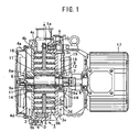
- Fig. 1 is a vertical sectional side view of one embodiment of a scroll fluid machine or a scroll vacuum pump according to the present invention, in which an orbiting scroll is revolved at a certain eccentricity, so that a gas through the circumference of a housing is sucked into a compressing portion between the orbiting scroll and a fixed scroll, compressed as it moves toward the center and discharged through the center.
- the numeral 1 denotes a housing having a closed disc-like compression chamber 2, and comprises a casing 3 and a cover 4, a sucking bore 1a being formed on the circumference.
- the housing 3 and cover 4 have fixed end plates 3a and 4a which surround the compression chamber 2 and oppose each other. Fixed wraps 3b and 4b are provided towards the compression chamber 2 to form the fixed scrolls 3c and 4c.
- a plurality of cooling radial fins 3d and 4d are provided on the outer sides of the fixed end plates 4a and 4a. Between the fixed end plates 3a and 4a in the compression chamber 2, the orbiting scroll 5 is provided to revolve around an axis of the compression chamber 2.
- the orbiting scroll 5 has an orbiting end plate 5a each surface of which has orbiting wraps 5b,5b engaged with the fixed scrolls 3c,4c, deviating by 180 degrees, and is rotatably supported on an eccentric axial portion 8a of a driving shaft 8 via a needle bearing 9 and a packing 9a.
- the driving shaft 8 is provided with bearings 6,7 in the center of the housing 1.
- the orbiting end plate 5a is engaged with the fixed end plate 3a via three known pin-crank rotation preventing mechanisms 10 spaced uniformly on the circumference. As the driving shaft 8 rotates, the orbiting end plate 5a eccentrically revolves in the compression chamber 2 to change a radial space between the fixed wraps 3b,4b and orbiting wraps 5b,5b engaged with each other.
- a plurality of axial gas-guiding bores 11,11 are formed near the center of the orbiting end plate 5a.
- the gas-guiding bore 11 above the eccentric axial portion 8a functions as compressed gas path and communicates at one end with a discharge bore 13 formed inwardly from the circumference of the fixed end plate 3a via an axial communicating bore 12 near the center of the fixed end plate 3a
- the driving shaft 8 has cooling fans 15,16 at the ends which extend from the fixed end plates 3a,4a.
- the cooling fans 15,15 suck air towards the center via the fins 3d,4d and discharge it away from the center.
- the orbiting scroll 5 rotatably mounted to the driving shaft 8 is revolved at a certain eccentricity while it is engaged with the fixed scroll 3c,4c, and air sucked through the sucking bore 1 a is compressed as it comes towards the center, thereby raising temperature.
- the inner ends of the heat pipes 14,14 in the gas-guiding bore 11 near the center of the orbiting scroll 5 are heated.
- the outer ends of the heat pipes 14,14 are projected from the fixed scrolls 3c,4c and cooled with the cooling fans 15,16 by air which flows via the cooling fins 3d,4d and circulates. So heat in the inner end of the heat pipe 14 or the orbiting scroll 5 is effectively released, thereby preventing excessive rise in temperature at the center of the orbiting scroll 5. Furthermore, the needle bearing 9 and packing 9a are not damaged with heat and enclosed grease is prevented
- heat-releasing rod, tube or plate made of high heat-conductive material such as Cu is made as heat-releasing rod and inserted into the gas-guiding bore 11.
- the outer ends are projected from the fixed end plates 3a and 4a and cooled with atmosphere.
- the projecting portions of the rod-like releasing material from the fixed end plates 3a,4a are made as flat as possible or as thin as possible, or a number of notches or wave-shape is formed to increase heat releasing effect.
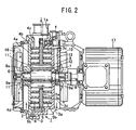
- Fig. 2 illustrates another embodiment of a scroll fluid machine, in which the same numerals are allotted to the same members as those in Fig. 1 and description therefor is omitted.
- Fig. 2 With nothing in a gas-guiding bore 11, cooling fans 15,16 with opposite pitches are rotated by a motor 17 to generate gas flow in a certain axial direction. Air is sucked from one end of the gas-guiding bore 11 by cooling fans 15,15 and discharged through the other end of the gas-guiding bore 11 after the gas-guiding bore 11 is effectively cooled.
- a heat pipe 14 or heat-releasing material as above is provided in the gas-guiding bore 11 thereby achieving more advantageous effect.
- the foregoing embodiments relate to a both-side scroll fluid machine in which both-side orbiting scrolls are provided between two fixed scrolls, but the present invention may also be applied to a one-side scroll fluid machine in which a one-side orbiting scroll is engaged with a one side fixed scroll.
Landscapes
- Engineering & Computer Science (AREA)
- Mechanical Engineering (AREA)
- General Engineering & Computer Science (AREA)
- Rotary Pumps (AREA)
- Applications Or Details Of Rotary Compressors (AREA)
- Structures Of Non-Positive Displacement Pumps (AREA)
Abstract
Description
- The present invention relates to a scroll fluid machine, and particularly to a scroll fluid machine, such as a scroll vacuum pump or a scroll pressurizing machine, in which a fixed wrap of a fixed scroll in a housing is engaged with an orbiting wrap of an orbiting scroll rotatably connected to an eccentric axial portion of a driving shaft, the orbiting scroll being revolved at a certain eccentricity by the driving shaft, thereby compressing a gas sucked from the circumference or the center of the housing as it moves toward the center or circumference and being discharged.
- Such a scroll fluid machine is known among persons skilled in the art. For example
EP 0902186 discloses a scroll-type fluid displacement machine andEP 0777053 discloses a scroll fluid machine. - A scroll fluid machine runs for a long time, so that temperatures of a driving shaft, an eccentric axial portion of the driving shaft, bearings and packings rise which can result in damage in the bearings and packings or in leak of lubricating oil. Hence in time the machine becomes impossible to use.
- To increase durability of the scroll fluid machine, it is necessary to avoid excessive high temperature on the eccentric axial portion of the driving shaft during long-time operation.
- To comply with such requirements, the following measures are taken and known among persons skilled in the art.
- (1) Low or room temperature air or nitrogen is introduced into a compressing portion of a scroll fluid machine to dilute toxicity in the compressing portion.
- (2) A gas-guiding bore is axially formed in a driving shaft, and a low or room temperature air or nitrogen is discharged through the gas-guiding bore. After it passes through the bearing, it is introduced into the compressing portion, which is cooled by the air or nitrogen which is discharged.
- (3) An eccentric axial portion of the driving shaft is formed as hollow into which low or room temperature air is introduced to cool the eccentric axial portion.
- However there are disadvantages as set out below in the foregoing measures.
- In order to introduce low or room temperature air or nitrogen into the compressing portion, it is necessary to provide introducing paths and outside supply means. Thus, the structure becomes complicated and makes its size larger which can result in higher cost.
- A gas-guiding bore is axially formed in a driving shaft, and low or room temperature air or nitrogen is discharged through the gas-guiding bore by centrifugal force caused by rotation of the driving shaft to cool bearings. In this device, when the driving shaft stops, a toxic or foreign-substance-containing gas in a compressing portion runs back and is discharged to atmosphere through the gas-guiding bore, thereby causing contamination in atmosphere.
- In view of the foregoing disadvantages, it is an object of the present invention to provide a scroll fluid machine in which air is introduced through the circumference of a housing during operation to cool an eccentric axial portion of a driving shaft, bearing therefor and other members automatically to increase durability.
- According to a first aspect of the present invention there is provided a scroll fluid machine comprising:
- a housing;
- a driving shaft having an eccentric axial portion;
- a fixed scroll having a fixed wrap in the housing;
- an orbiting scroll having an orbiting wrap;
- a bearing provided between the orbital scroll and the eccentric axial portion of the driving shaft to allow the orbiting scroll to revolve around the eccentric axial portion by the driving shaft so that a gas sucked through a circumference of the housing is compressed as it moves toward a center of the orbiting scroll and discharged; characterised by
- a gas-guiding bore formed axially in the orbiting scroll close to and radially outside the bearing, and a cooling fan rotated by the driving shaft near an opening end of the gas-guiding bore thereby allowing air flow generated by the cooling fan to pass through the gas-guiding bore to reduce heat transfer of the compressed gas to the bearing to cool the bearing.
- The above and other features and advantages of the invention will become more apparent from the following description with respect to embodiments as shown in appended drawings wherein:
-
Fig. 1 is a vertical sectional side view of an embodiment of a scroll fluid machine according to the present invention; and -
Fig. 2 is a vertical sectional side view of another embodiment of a scroll fluid machine according to the present invention. -
Fig. 1 is a vertical sectional side view of one embodiment of a scroll fluid machine or a scroll vacuum pump according to the present invention, in which an orbiting scroll is revolved at a certain eccentricity, so that a gas through the circumference of a housing is sucked into a compressing portion between the orbiting scroll and a fixed scroll, compressed as it moves toward the center and discharged through the center. - The numeral 1 denotes a housing having a closed disc-
like compression chamber 2, and comprises acasing 3 and acover 4, asucking bore 1a being formed on the circumference. - The
housing 3 andcover 4 have fixedend plates compression chamber 2 and oppose each other. Fixedwraps compression chamber 2 to form thefixed scrolls - A plurality of cooling
radial fins end plates fixed end plates compression chamber 2, theorbiting scroll 5 is provided to revolve around an axis of thecompression chamber 2. - The orbiting
scroll 5 has an orbitingend plate 5a each surface of which has orbitingwraps fixed scrolls axial portion 8a of adriving shaft 8 via a needle bearing 9 and apacking 9a. Thedriving shaft 8 is provided withbearings - The orbiting
end plate 5a is engaged with the fixedend plate 3a via three known pin-crankrotation preventing mechanisms 10 spaced uniformly on the circumference. As thedriving shaft 8 rotates, the orbitingend plate 5a eccentrically revolves in thecompression chamber 2 to change a radial space between the fixedwraps wraps - A plurality of axial gas-guiding
bores end plate 5a. The gas-guiding bore 11 above the eccentricaxial portion 8a functions as compressed gas path and communicates at one end with adischarge bore 13 formed inwardly from the circumference of the fixedend plate 3a via an axial communicating bore 12 near the center of the fixedend plate 3a - Two
heat pipes axial portion 8a inFig. 1 , and the outer end of each of theheat pipes 14 passes through the fixedend plates cooling fins cooling fins - Thus, projecting portions of the
heat pipes 14 from the fixedend plates fins - The
driving shaft 8 has coolingfans end plates cooling fans fins - When the driving
shaft 8 is rotated by amotor 17, theorbiting scroll 5 rotatably mounted to the drivingshaft 8 is revolved at a certain eccentricity while it is engaged with thefixed scroll sucking bore 1 a is compressed as it comes towards the center, thereby raising temperature. Thus, the inner ends of theheat pipes bore 11 near the center of the orbitingscroll 5 are heated. - However, the outer ends of the
heat pipes fixed scrolls cooling fans cooling fins heat pipe 14 or the orbitingscroll 5 is effectively released, thereby preventing excessive rise in temperature at the center of the orbitingscroll 5. Furthermore, the needle bearing 9 and packing 9a are not damaged with heat and enclosed grease is prevented - Instead of the
heat pipe 14, heat-releasing rod, tube or plate made of high heat-conductive material such as Cu is made as heat-releasing rod and inserted into the gas-guidingbore 11. The outer ends are projected from the fixedend plates end plates -
Fig. 2 illustrates another embodiment of a scroll fluid machine, in which the same numerals are allotted to the same members as those inFig. 1 and description therefor is omitted. - In
Fig. 2 , with nothing in a gas-guidingbore 11,cooling fans motor 17 to generate gas flow in a certain axial direction. Air is sucked from one end of the gas-guidingbore 11 bycooling fans bore 11 after the gas-guidingbore 11 is effectively cooled. In addition to such device in which gas flow is generated in one axial direction, aheat pipe 14 or heat-releasing material as above is provided in the gas-guidingbore 11 thereby achieving more advantageous effect. - The foregoing embodiments relate to a both-side scroll fluid machine in which both-side orbiting scrolls are provided between two fixed scrolls, but the present invention may also be applied to a one-side scroll fluid machine in which a one-side orbiting scroll is engaged with a one side fixed scroll.
- The foregoing examples merely relate to embodiments of the invention. Various changes and modifications may be made by a person skilled in the art without departing from the scope of claims.
Claims (4)
- A scroll fluid machine comprising:a housing (1);a driving shaft (8) having an eccentric axial portion (8a);a fixed scroll (3c, 4c) having a fixed wrap (3b, 4b) in the housing;an orbiting scroll (5) having an orbiting wrap (5b);a bearing provided between the orbital scroll (5) and the eccentric axial portion (8a) of the driving shaft to allow the orbiting scroll to revolve around the eccentric axial portion (8a) by the driving shaft (8) so that a gas sucked through a circumference of the housing (1) is compressed as it moves toward a center of the orbiting scroll (5) and discharged; characterised bya gas-guiding bore (11) formed axially in the orbiting scroll (5) close to and radially outside the bearing (9), and a cooling fan rotated by the driving shaft (8) near an opening end of the gas-guiding bore (11) thereby allowing air flow generated by the cooling fan to pass through the gas-guiding bore (11) to reduce heat transfer of the compressed gas to the bearing (9) to cool the bearing.
- A scroll fluid machine as claimed in claim 1 wherein the bearing (9) comprises a needle bearing.
- A scroll fluid machine as claimed in claim 1 or 2 wherein a heat-releasing rod (14) is inserted in the gas-guiding bore (11), one end of the heat-releasing rod (14) being projected from the fixed scroll (3c, 4c) to release heat to atmosphere.
- A scroll fluid machine as claimed in claim 3 wherein the heat-releasing rod (14) comprises a heat pipe.
Applications Claiming Priority (2)
| Application Number | Priority Date | Filing Date | Title |
|---|---|---|---|
| JP2003146608 | 2003-05-23 | ||
| JP2003146608A JP4373130B2 (en) | 2003-05-23 | 2003-05-23 | Scroll fluid machinery |
Publications (2)
| Publication Number | Publication Date |
|---|---|
| EP1479916A1 EP1479916A1 (en) | 2004-11-24 |
| EP1479916B1 true EP1479916B1 (en) | 2008-09-03 |
Family
ID=33095498
Family Applications (1)
| Application Number | Title | Priority Date | Filing Date |
|---|---|---|---|
| EP04011852A Expired - Lifetime EP1479916B1 (en) | 2003-05-23 | 2004-05-19 | Scroll fluid machine |
Country Status (6)
| Country | Link |
|---|---|
| US (2) | US7121816B2 (en) |
| EP (1) | EP1479916B1 (en) |
| JP (1) | JP4373130B2 (en) |
| CN (1) | CN100340772C (en) |
| AT (1) | ATE407295T1 (en) |
| DE (1) | DE602004016250D1 (en) |
Families Citing this family (28)
| Publication number | Priority date | Publication date | Assignee | Title |
|---|---|---|---|---|
| DE3333678A1 (en) * | 1983-09-17 | 1985-03-28 | Basf Ag, 6700 Ludwigshafen | METHOD FOR PRODUCING 3-FORMYL-TETRAHYDROTHIOPYRANES |
| JP4629546B2 (en) | 2005-09-30 | 2011-02-09 | アネスト岩田株式会社 | Scroll fluid machinery |
| JP2007198153A (en) * | 2006-01-24 | 2007-08-09 | Anest Iwata Corp | Scroll fluid machine |
| JP4768457B2 (en) * | 2006-01-27 | 2011-09-07 | アネスト岩田株式会社 | Scroll fluid machinery |
| JP5020628B2 (en) * | 2006-12-26 | 2012-09-05 | アネスト岩田株式会社 | Scroll fluid machinery |
| US8459971B2 (en) * | 2008-09-26 | 2013-06-11 | Honda Motor Co., Ltd. | Scroll compressor with balancer and oil passages |
| US8177534B2 (en) * | 2008-10-30 | 2012-05-15 | Advanced Scroll Technologies (Hangzhou), Inc. | Scroll-type fluid displacement apparatus with improved cooling system |
| JP2011004467A (en) * | 2009-06-16 | 2011-01-06 | Panasonic Corp | Motor and electronic device using the same |
| JP2011080366A (en) * | 2009-10-02 | 2011-04-21 | Anest Iwata Corp | Motor-directly connected compressor unit |
| JP5109042B2 (en) * | 2010-09-07 | 2012-12-26 | 株式会社リッチストーン | Scroll fluid machinery |
| CN102071973B (en) * | 2011-01-07 | 2012-12-19 | 山东科技大学 | Scroll compression-expansion compound machine for compressed air energy storage technology |
| KR101462941B1 (en) | 2012-03-07 | 2014-11-19 | 엘지전자 주식회사 | Horizontal type scroll compressor |
| JP5998028B2 (en) * | 2012-11-30 | 2016-09-28 | 株式会社日立産機システム | Scroll type fluid machine |
| US9611852B2 (en) * | 2013-03-29 | 2017-04-04 | Agilent Technology, Inc. | Thermal/noise management in a scroll pump |
| US10208753B2 (en) | 2013-03-29 | 2019-02-19 | Agilent Technologies, Inc. | Thermal/noise management in a scroll pump |
| CN103306973A (en) * | 2013-05-29 | 2013-09-18 | 沈阳纪维应用技术有限公司 | Oilless vortex fluid mechanical device |
| US10865793B2 (en) | 2016-12-06 | 2020-12-15 | Air Squared, Inc. | Scroll type device having liquid cooling through idler shafts |
| EP3727837A4 (en) | 2017-12-19 | 2021-09-08 | Saint-Gobain ADFORS Canada, Ltd. | REINFORCEMENT LAYER, CEMENT SHEET AND METHOD FOR MANUFACTURING THE CEMENT SHEET |
| JP7042364B2 (en) | 2018-05-04 | 2022-03-25 | エア・スクエアード・インコーポレイテッド | Liquid cooling of fixed scroll and swivel scroll compressors, expanders, or vacuum pumps |
| US11067080B2 (en) * | 2018-07-17 | 2021-07-20 | Air Squared, Inc. | Low cost scroll compressor or vacuum pump |
| US20200025199A1 (en) | 2018-07-17 | 2020-01-23 | Air Squared, Inc. | Dual drive co-rotating spinning scroll compressor or expander |
| US11530703B2 (en) | 2018-07-18 | 2022-12-20 | Air Squared, Inc. | Orbiting scroll device lubrication |
| CN110319002B (en) * | 2019-06-25 | 2020-08-18 | 珠海格力电器股份有限公司 | Compressor with a compressor housing having a plurality of compressor blades |
| US11473572B2 (en) | 2019-06-25 | 2022-10-18 | Air Squared, Inc. | Aftercooler for cooling compressed working fluid |
| US11898557B2 (en) | 2020-11-30 | 2024-02-13 | Air Squared, Inc. | Liquid cooling of a scroll type compressor with liquid supply through the crankshaft |
| US11885328B2 (en) | 2021-07-19 | 2024-01-30 | Air Squared, Inc. | Scroll device with an integrated cooling loop |
| US12510080B2 (en) * | 2022-12-15 | 2025-12-30 | Agilent Technologies, Inc. | Fluid pump and enclosure providing stator holder and cooling for motor and electronics |
| US20250020137A1 (en) * | 2023-06-09 | 2025-01-16 | Scott Fetzer/Powerex-Iwata Air Technology Inc. | Cooling attachment system for compressor motor assembly |
Family Cites Families (10)
| Publication number | Priority date | Publication date | Assignee | Title |
|---|---|---|---|---|
| US3842596A (en) * | 1970-07-10 | 1974-10-22 | V Gray | Methods and apparatus for heat transfer in rotating bodies |
| JPS5835389A (en) * | 1981-08-26 | 1983-03-02 | Hisateru Akachi | Rotary-type heat pipe and production thereof |
| DE3810052A1 (en) * | 1987-04-08 | 1988-10-20 | Volkswagen Ag | Cooling arrangement |
| US5101888A (en) * | 1990-12-03 | 1992-04-07 | Rockwell International Corporation | Heat pipe systems |
| US5417554A (en) * | 1994-07-19 | 1995-05-23 | Ingersoll-Rand Company | Air cooling system for scroll compressors |
| JP3423514B2 (en) * | 1995-11-30 | 2003-07-07 | アネスト岩田株式会社 | Scroll fluid machine |
| JPH1026090A (en) * | 1996-07-08 | 1998-01-27 | Asuka Japan:Kk | Ventilation-cooled scroll fluid machine |
| JP3478940B2 (en) * | 1997-03-04 | 2003-12-15 | 株式会社日立産機システム | Scroll compressor |
| JPH1182333A (en) * | 1997-09-12 | 1999-03-26 | Kimie Nakamura | Scroll fluid machine |
| JP2000345972A (en) * | 1999-06-07 | 2000-12-12 | Hitachi Ltd | Double tooth scroll compressor |
-
2003
- 2003-05-23 JP JP2003146608A patent/JP4373130B2/en not_active Expired - Fee Related
-
2004
- 2004-05-19 AT AT04011852T patent/ATE407295T1/en not_active IP Right Cessation
- 2004-05-19 EP EP04011852A patent/EP1479916B1/en not_active Expired - Lifetime
- 2004-05-19 DE DE602004016250T patent/DE602004016250D1/en not_active Expired - Lifetime
- 2004-05-21 US US10/850,639 patent/US7121816B2/en not_active Expired - Fee Related
- 2004-05-21 CN CNB2004100477426A patent/CN100340772C/en not_active Expired - Fee Related
-
2006
- 2006-06-22 US US11/425,760 patent/US7241121B2/en not_active Expired - Fee Related
Also Published As
| Publication number | Publication date |
|---|---|
| US7241121B2 (en) | 2007-07-10 |
| US20040241030A1 (en) | 2004-12-02 |
| US20060233656A1 (en) | 2006-10-19 |
| ATE407295T1 (en) | 2008-09-15 |
| CN1573118A (en) | 2005-02-02 |
| DE602004016250D1 (en) | 2008-10-16 |
| JP2004346870A (en) | 2004-12-09 |
| EP1479916A1 (en) | 2004-11-24 |
| CN100340772C (en) | 2007-10-03 |
| JP4373130B2 (en) | 2009-11-25 |
| US7121816B2 (en) | 2006-10-17 |
Similar Documents
| Publication | Publication Date | Title |
|---|---|---|
| US7241121B2 (en) | Scroll fluid machine | |
| EP2361352B1 (en) | Scroll-type fluid displacement apparatus with improved cooling system | |
| KR101286187B1 (en) | Multistage dry vaccum pump | |
| EP1770243B1 (en) | Scroll fluid machine | |
| CN111670307B (en) | Scroll with liquid cooling via driven shaft | |
| JP4999157B2 (en) | Fluid machine coupled to drive source via magnetic coupling | |
| JPH09151868A (en) | Scroll fluid machinery | |
| US7419371B2 (en) | Scroll fluid machine | |
| JPH04272402A (en) | Scroll device with ensured flow of lubricant | |
| US6953330B1 (en) | Scroll vacuum pump | |
| JP4837416B2 (en) | Scroll fluid machinery | |
| JPH04342801A (en) | Scroll type hydraulic machine | |
| JP2003193987A (en) | Scroll fluid machine | |
| JP2008164095A (en) | Magnetic coupling device | |
| KR101886668B1 (en) | Scroll fluid machine | |
| US6589026B2 (en) | Fluid machinery having a helical mechanism with through holes for ventilation | |
| CN111022317B (en) | scroll compressor | |
| JP3137109B2 (en) | Scroll compressor and orbiting scroll used for it | |
| EP1626178B1 (en) | Scroll vacuum pump | |
| JP2004316440A (en) | Scroll pressure reducing machine | |
| JPH08326677A (en) | Hermetic compressor | |
| JP3653128B2 (en) | Scroll type fluid machine | |
| EP1820968B1 (en) | Scroll fluid machine | |
| JPH0347494A (en) | Scroll compressor |
Legal Events
| Date | Code | Title | Description |
|---|---|---|---|
| PUAI | Public reference made under article 153(3) epc to a published international application that has entered the european phase |
Free format text: ORIGINAL CODE: 0009012 |
|
| AK | Designated contracting states |
Kind code of ref document: A1 Designated state(s): AT BE BG CH CY CZ DE DK EE ES FI FR GB GR HU IE IT LI LU MC NL PL PT RO SE SI SK TR |
|
| AX | Request for extension of the european patent |
Extension state: AL HR LT LV MK |
|
| 17P | Request for examination filed |
Effective date: 20041122 |
|
| AKX | Designation fees paid |
Designated state(s): AT BE BG CH CY CZ DE DK EE ES FI FR GB GR HU IE IT LI LU MC NL PL PT RO SE SI SK TR |
|
| 17Q | First examination report despatched |
Effective date: 20060714 |
|
| GRAP | Despatch of communication of intention to grant a patent |
Free format text: ORIGINAL CODE: EPIDOSNIGR1 |
|
| GRAS | Grant fee paid |
Free format text: ORIGINAL CODE: EPIDOSNIGR3 |
|
| GRAA | (expected) grant |
Free format text: ORIGINAL CODE: 0009210 |
|
| AK | Designated contracting states |
Kind code of ref document: B1 Designated state(s): AT BE BG CH CY CZ DE DK EE ES FI FR GB GR HU IE IT LI LU MC NL PL PT RO SE SI SK TR |
|
| REG | Reference to a national code |
Ref country code: GB Ref legal event code: FG4D |
|
| REG | Reference to a national code |
Ref country code: CH Ref legal event code: EP |
|
| REG | Reference to a national code |
Ref country code: IE Ref legal event code: FG4D |
|
| REF | Corresponds to: |
Ref document number: 602004016250 Country of ref document: DE Date of ref document: 20081016 Kind code of ref document: P |
|
| PG25 | Lapsed in a contracting state [announced via postgrant information from national office to epo] |
Ref country code: ES Free format text: LAPSE BECAUSE OF FAILURE TO SUBMIT A TRANSLATION OF THE DESCRIPTION OR TO PAY THE FEE WITHIN THE PRESCRIBED TIME-LIMIT Effective date: 20081214 Ref country code: NL Free format text: LAPSE BECAUSE OF FAILURE TO SUBMIT A TRANSLATION OF THE DESCRIPTION OR TO PAY THE FEE WITHIN THE PRESCRIBED TIME-LIMIT Effective date: 20080903 |
|
| PG25 | Lapsed in a contracting state [announced via postgrant information from national office to epo] |
Ref country code: SI Free format text: LAPSE BECAUSE OF FAILURE TO SUBMIT A TRANSLATION OF THE DESCRIPTION OR TO PAY THE FEE WITHIN THE PRESCRIBED TIME-LIMIT Effective date: 20080903 Ref country code: FI Free format text: LAPSE BECAUSE OF FAILURE TO SUBMIT A TRANSLATION OF THE DESCRIPTION OR TO PAY THE FEE WITHIN THE PRESCRIBED TIME-LIMIT Effective date: 20080903 Ref country code: AT Free format text: LAPSE BECAUSE OF FAILURE TO SUBMIT A TRANSLATION OF THE DESCRIPTION OR TO PAY THE FEE WITHIN THE PRESCRIBED TIME-LIMIT Effective date: 20080903 |
|
| NLV1 | Nl: lapsed or annulled due to failure to fulfill the requirements of art. 29p and 29m of the patents act | ||
| PG25 | Lapsed in a contracting state [announced via postgrant information from national office to epo] |
Ref country code: BE Free format text: LAPSE BECAUSE OF FAILURE TO SUBMIT A TRANSLATION OF THE DESCRIPTION OR TO PAY THE FEE WITHIN THE PRESCRIBED TIME-LIMIT Effective date: 20080903 |
|
| PG25 | Lapsed in a contracting state [announced via postgrant information from national office to epo] |
Ref country code: BG Free format text: LAPSE BECAUSE OF FAILURE TO SUBMIT A TRANSLATION OF THE DESCRIPTION OR TO PAY THE FEE WITHIN THE PRESCRIBED TIME-LIMIT Effective date: 20081203 |
|
| PG25 | Lapsed in a contracting state [announced via postgrant information from national office to epo] |
Ref country code: CZ Free format text: LAPSE BECAUSE OF FAILURE TO SUBMIT A TRANSLATION OF THE DESCRIPTION OR TO PAY THE FEE WITHIN THE PRESCRIBED TIME-LIMIT Effective date: 20080903 Ref country code: SK Free format text: LAPSE BECAUSE OF FAILURE TO SUBMIT A TRANSLATION OF THE DESCRIPTION OR TO PAY THE FEE WITHIN THE PRESCRIBED TIME-LIMIT Effective date: 20080903 Ref country code: RO Free format text: LAPSE BECAUSE OF FAILURE TO SUBMIT A TRANSLATION OF THE DESCRIPTION OR TO PAY THE FEE WITHIN THE PRESCRIBED TIME-LIMIT Effective date: 20080903 Ref country code: PT Free format text: LAPSE BECAUSE OF FAILURE TO SUBMIT A TRANSLATION OF THE DESCRIPTION OR TO PAY THE FEE WITHIN THE PRESCRIBED TIME-LIMIT Effective date: 20090203 |
|
| PLBE | No opposition filed within time limit |
Free format text: ORIGINAL CODE: 0009261 |
|
| STAA | Information on the status of an ep patent application or granted ep patent |
Free format text: STATUS: NO OPPOSITION FILED WITHIN TIME LIMIT |
|
| PG25 | Lapsed in a contracting state [announced via postgrant information from national office to epo] |
Ref country code: DK Free format text: LAPSE BECAUSE OF FAILURE TO SUBMIT A TRANSLATION OF THE DESCRIPTION OR TO PAY THE FEE WITHIN THE PRESCRIBED TIME-LIMIT Effective date: 20080903 Ref country code: EE Free format text: LAPSE BECAUSE OF FAILURE TO SUBMIT A TRANSLATION OF THE DESCRIPTION OR TO PAY THE FEE WITHIN THE PRESCRIBED TIME-LIMIT Effective date: 20080903 |
|
| 26N | No opposition filed |
Effective date: 20090604 |
|
| PG25 | Lapsed in a contracting state [announced via postgrant information from national office to epo] |
Ref country code: IT Free format text: LAPSE BECAUSE OF FAILURE TO SUBMIT A TRANSLATION OF THE DESCRIPTION OR TO PAY THE FEE WITHIN THE PRESCRIBED TIME-LIMIT Effective date: 20080903 |
|
| PG25 | Lapsed in a contracting state [announced via postgrant information from national office to epo] |
Ref country code: MC Free format text: LAPSE BECAUSE OF NON-PAYMENT OF DUE FEES Effective date: 20090531 |
|
| REG | Reference to a national code |
Ref country code: CH Ref legal event code: PL |
|
| PG25 | Lapsed in a contracting state [announced via postgrant information from national office to epo] |
Ref country code: SE Free format text: LAPSE BECAUSE OF FAILURE TO SUBMIT A TRANSLATION OF THE DESCRIPTION OR TO PAY THE FEE WITHIN THE PRESCRIBED TIME-LIMIT Effective date: 20081203 Ref country code: LI Free format text: LAPSE BECAUSE OF NON-PAYMENT OF DUE FEES Effective date: 20090531 Ref country code: CH Free format text: LAPSE BECAUSE OF NON-PAYMENT OF DUE FEES Effective date: 20090531 |
|
| REG | Reference to a national code |
Ref country code: FR Ref legal event code: ST Effective date: 20100129 |
|
| PG25 | Lapsed in a contracting state [announced via postgrant information from national office to epo] |
Ref country code: IE Free format text: LAPSE BECAUSE OF NON-PAYMENT OF DUE FEES Effective date: 20090519 Ref country code: FR Free format text: LAPSE BECAUSE OF NON-PAYMENT OF DUE FEES Effective date: 20090602 |
|
| PG25 | Lapsed in a contracting state [announced via postgrant information from national office to epo] |
Ref country code: PL Free format text: LAPSE BECAUSE OF FAILURE TO SUBMIT A TRANSLATION OF THE DESCRIPTION OR TO PAY THE FEE WITHIN THE PRESCRIBED TIME-LIMIT Effective date: 20080903 |
|
| PG25 | Lapsed in a contracting state [announced via postgrant information from national office to epo] |
Ref country code: GR Free format text: LAPSE BECAUSE OF FAILURE TO SUBMIT A TRANSLATION OF THE DESCRIPTION OR TO PAY THE FEE WITHIN THE PRESCRIBED TIME-LIMIT Effective date: 20081204 |
|
| PG25 | Lapsed in a contracting state [announced via postgrant information from national office to epo] |
Ref country code: LU Free format text: LAPSE BECAUSE OF NON-PAYMENT OF DUE FEES Effective date: 20090519 |
|
| PG25 | Lapsed in a contracting state [announced via postgrant information from national office to epo] |
Ref country code: HU Free format text: LAPSE BECAUSE OF FAILURE TO SUBMIT A TRANSLATION OF THE DESCRIPTION OR TO PAY THE FEE WITHIN THE PRESCRIBED TIME-LIMIT Effective date: 20090304 |
|
| PG25 | Lapsed in a contracting state [announced via postgrant information from national office to epo] |
Ref country code: TR Free format text: LAPSE BECAUSE OF FAILURE TO SUBMIT A TRANSLATION OF THE DESCRIPTION OR TO PAY THE FEE WITHIN THE PRESCRIBED TIME-LIMIT Effective date: 20080903 |
|
| PG25 | Lapsed in a contracting state [announced via postgrant information from national office to epo] |
Ref country code: CY Free format text: LAPSE BECAUSE OF FAILURE TO SUBMIT A TRANSLATION OF THE DESCRIPTION OR TO PAY THE FEE WITHIN THE PRESCRIBED TIME-LIMIT Effective date: 20080903 |
|
| PGFP | Annual fee paid to national office [announced via postgrant information from national office to epo] |
Ref country code: DE Payment date: 20120523 Year of fee payment: 9 |
|
| PGFP | Annual fee paid to national office [announced via postgrant information from national office to epo] |
Ref country code: GB Payment date: 20120522 Year of fee payment: 9 |
|
| GBPC | Gb: european patent ceased through non-payment of renewal fee |
Effective date: 20130519 |
|
| PG25 | Lapsed in a contracting state [announced via postgrant information from national office to epo] |
Ref country code: DE Free format text: LAPSE BECAUSE OF NON-PAYMENT OF DUE FEES Effective date: 20131203 |
|
| REG | Reference to a national code |
Ref country code: DE Ref legal event code: R119 Ref document number: 602004016250 Country of ref document: DE Effective date: 20131203 |
|
| PG25 | Lapsed in a contracting state [announced via postgrant information from national office to epo] |
Ref country code: GB Free format text: LAPSE BECAUSE OF NON-PAYMENT OF DUE FEES Effective date: 20130519 |