EP1479635A1 - Überwachungsverfahren und Überwachungssystem zum Überwachen der Beleuchtung einer Aufzugskabine - Google Patents
Überwachungsverfahren und Überwachungssystem zum Überwachen der Beleuchtung einer Aufzugskabine Download PDFInfo
- Publication number
- EP1479635A1 EP1479635A1 EP04011227A EP04011227A EP1479635A1 EP 1479635 A1 EP1479635 A1 EP 1479635A1 EP 04011227 A EP04011227 A EP 04011227A EP 04011227 A EP04011227 A EP 04011227A EP 1479635 A1 EP1479635 A1 EP 1479635A1
- Authority
- EP
- European Patent Office
- Prior art keywords
- light
- sensor
- signal
- test
- control signal
- Prior art date
- Legal status (The legal status is an assumption and is not a legal conclusion. Google has not performed a legal analysis and makes no representation as to the accuracy of the status listed.)
- Granted
Links
Images

Classifications
-
- B—PERFORMING OPERATIONS; TRANSPORTING
- B66—HOISTING; LIFTING; HAULING
- B66B—ELEVATORS; ESCALATORS OR MOVING WALKWAYS
- B66B1/00—Control systems of elevators in general
- B66B1/34—Details, e.g. call counting devices, data transmission from car to control system, devices giving information to the control system
Definitions
- the invention relates to a monitoring method for Monitoring the lighting of an elevator car after the Preamble of claim 1, and a monitoring system for Implementation of these procedures according to the preamble of Claim 6.
- Elevator cabs especially those that are only or also for the transportation of people are provided in the Generally a lighting device with which they are illuminated. In some countries / is one Lighting is even mandatory for elevator cars required. To make sure that the Lighting device works properly, must always check whether the elevator car is illuminated is. To rationalize such a review of lighting it is advantageous if a automatic monitoring system is available, which allows remote monitoring. This saves you regular checks on site.
- a possible monitoring system has a light sensor on, which detects whether in the elevator car Illumination light is present. Monitoring is in realized this surveillance system in that the Lights in the elevator car switched off from time to time becomes. Then the reaction of the light sensor is observed. A statement can then be made as to whether the The lighting fixture and the sensor work together. It is a disadvantage of this surveillance system that Cabin light must be switched off. A shutdown the cabin light can preferably only then be made when the elevator is not occupied is. A malfunctioning cabin lighting or a defective sensor can only work with some Delay can be determined.
- the monitoring system described above has one serious disadvantage. If the sensor at the output shows that no light signal was detected, it can be deduced from this can not be concluded whether the lighting device for the elevator car is actually defective. It is possible that the lighting device of the elevator car is defective or does not work as intended. It is but also possible that the lighting device is intact is and works properly, but that is a defect on one of the components of the surveillance system, in particular on the light sensor itself. To such It is with this monitoring system that defects are found unavoidable to take a patrol to clarify on site whether the Lighting device or a component of the Surveillance system is not working properly.
- the monitoring system is a surveillance system that is a real one Remote monitoring allowed.
- This surveillance system shows like the previously known surveillance system, a light sensor on.
- the monitoring system has one Influencing unit, which in the broadest sense as Modulator can be called.
- the influencing unit can be controlled by means of a control signal so that it especially one that changes in short time intervals Can influence the illumination light, or in other words, the characteristic of this Illuminating light to be detected by the light sensor is can change. This influence takes place before the illuminating light or part of the rays of the Illumination light is detected by the light sensor. Since that light detected by the light sensor was previously influenced, is the sensor signal which the light sensor is available correlates with that part of the rays that were influenced.
- the monitoring system points in Another processing unit.
- the Processing unit processes the sensor signal of the Light sensor together with the control signal, such that can be determined whether the sensor signal of the Light sensor has a characteristic which corresponds to that of the control signal or with the Control signal is correlated. In this case it will Sensor signal considered "valid".
- the processing unit finally sets Information signal ready by the result of Processing of the control signal and the sensor signal is determined.
- the information signal indicates that the sensor signal of the light sensor the control signal for the Influencing unit corresponds, respectively with the Control signal is correlated, so it can be concluded that neither malfunction of anybody Component of the surveillance system still a failure of There is a light source.
- the information signal indicates that the sensor signal the light sensor not the control signal for the Influencing unit corresponds, or not with the Control signal is correlated, so it can be concluded that a malfunction of a component of the Surveillance system exists, but the lighting of the Elevator car still works because in the event of a failure of the The light sensor would not provide a sensor signal for lighting Can provide.
- a variant of the new monitoring system points in addition to the lighting device or light source for the lighting of the elevator car is a test light source on at any time regardless of the operation of the elevator system can be temporarily activated.
- the test light source emits too
- the light sensor points to this as above with reference described on the illuminating light, a test sensor signal to disposal.
- This test sensor signal will from the processing unit together with the control signal processed for the influencing unit.
- Correspond are the test sensor signal and the control signal, respectively the two signals correlated with each other, so that indicates Monitoring system no defect on (the test sensor signal is called valid).
- the information signals can be used to identify a trigger optical or acoustic alarm, which may also connected to a mobile device of an operator can be.
- a service call can also be made become.
- Other reactions can also be triggered, to meet the requirements of a standard, for example.
- the light sensor preferably arranged so that it is only sensitive to light from the lighting device (or the test light source) the elevator car is emitted.
- Other Light for example temporary ambient light, for a short time light caused by a passenger in the elevator car, for example when lighting a smoking article or light below a certain intensity should be from the sensor as far as possible not to be detected in order to cause interference avoid.
- Corresponding filters can also be used for the light sensor upstream to suppress stray light.
- the light sensor is so is designed so that he only has a signal available represents when the intensity of the detected light is within certain limits.
- the influencing unit can, as already mentioned, as Be designed modulator.
- the modulator can be designed as an LCD modulator.
- the control signal for the influencing unit is advantageously from the processing unit to Provided.
- the test light source can also be from or across the Processing unit can be checked
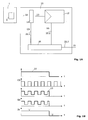
- FIG. 1A shows a first overall system, with one too monitoring lighting system 1 and one after the Invention designed surveillance system 10.
- Das Lighting system 1 has a light source 2, which for lighting an elevator car, not shown serves.
- the lighting system 1 shown, or Light source 2 is switched on using the monitoring system 10 supervised.
- the monitoring system 10 includes one Detection unit in the form of a light sensor 12, a Influencing unit 14 and a processing unit 16, and electrical conductor arrangements 20.1, 20.2 and 20.3, which can also be designed as light guides, for example can.
- a processing unit 16 is over the first Conductor arrangement 20.1 with the influencing unit 14 and via the second conductor arrangement 20.2 with the light sensor 12 connected. Via a third conductor arrangement 20.3 Information signal IS provided.
- the light source 2 emits during the illumination of the Elevator car illumination light 22 with first optical Characteristics. To be precise, only a certain part of the beams emitted by the light source 2, which also is designated 22 for the monitoring method used.
- the influencing unit 14, or its function is controlled by a control signal CS.
- the control signal CS comes from the present embodiment Processing unit 16, but this is not mandatory Case. It is only important that the control signal CS, or Information about the control signal CS, the Processing unit 16 is available because that Control signal CS, or information about the control signal CS, needed for an evaluation / processing of the signal SS as described below.
- the influencing unit 14 is designed or controlled that illuminating light 22 striking them is influenced in such a way that the emerging light 23 is changed compared to the illuminating light 22, wherein this change is preferably a periodic change is.
- the emerging light 23 can, for example, be in change short time intervals.
- the duration change of the emerging light 23 depends on the type of influencing unit 14 and can temporal, spatial or other type of change.
- the influencing unit is preferably involved 14 around a modulator that the illuminating light 22 to Example modulated by a light-dark keying.
- the influencing unit 14 thus Illuminating light 22 influences, or there will be Properties changed. That influenced or changed Light is called exiting or influenced Designated light 23.
- This influenced light 23 is from Light sensor 12 detected.
- the light sensor 12 now provides the processing unit 16 a sensor signal SS Available with the light 23 or the properties of the Light 23 is correlated.
- the processing unit 16 processes the two signals available to her, namely the control signal CS and the sensor signal SS, and based on the processed signals CS and SS an information signal IS ready, which about existing malfunctions of the lighting device 1 or light source 2 and / or the monitoring system 10 Provides information.
- the information signal IS enables a statement to be made about whether illuminating light 22 is present and whether it is the sensor signal SS is a valid signal.
- Fig. 1B The operation of the monitoring system is in Fig. 1B, each depicted as a function of time t. At the top is the course of the not yet influenced Light 22 shown.
- Light 22 is initially emitted, which is simplistically assumed to be a has constant intensity. After a period of time light 22 is no longer emitted, either because the Elevator car is no longer used, or because the Light source 2 is defective.
- control signal CS for control the influencing unit 14 is in the example shown uses a square wave signal. This is regardless of whether Light 22 is emitted.
- the control signal CS causes that the influencing unit 14 the light 22 so modified that the light 23 results.
- the Characteristic in a clear manner from the control signal CS is influenced.
- the sensor signal SS is available. If the light sensor 12 is working properly, there is a correlation between the light 23 and the sensor signal SS.
- a liquid crystal system (LCD) Influencing unit 14 are used, depending on Activation by control signal CS either light 22 lets through or blocked.
- control signal CS for the Influencing unit 14 as already mentioned, for Example assumed a square wave.
- the Influencing unit 14 thereby acts alternately during obscuring a time unit or transparent. It occurs thus temporarily no or substantially less light 23.
- the light 23 thus forms also a kind of rectangular function, compared to the Control signal CS can be shifted in time, but with this is correlated.
- the course of the sensor signal SS which with the light 23rd correlated also corresponds to a type Rectangular function, in a case where none Malfunctions occur.
- the information signal IS allows a "yes statement” if everything works properly, otherwise it allows Information signal a 'no statement'.
- the 'yes' statement is in Fig. 1B with a logical, 1 'and the' no statement ' indicated with a logical '0'.
- Fig. 2 shows a further arrangement according to the invention, the is suitable in addition to that related to Fig. 1 described function also the overall system consisting of the lighting system 1 and the Monitoring system 10 to monitor.
- the Test light source 102 is independent of light source 2 and in the present embodiment via a Conductor arrangement 20.4 with the processing unit 16 connected, but this is not absolutely necessary.
- the test light source 102 emits test light 122 that in the same Way as the illuminating light 22 from the Influencing unit 14 influences and light 23 is changed.
- the mode of operation of the arrangement according to FIG. 2 is The following: With the help of the test light source 102 determined whether the monitoring system 10 is working properly works, regardless of the function of the Light source 2. If it is found that the Monitoring system 10 is working properly, so can it for continuous remote monitoring of the Lighting system 1 are used, as above is described. In this case, this is from sensor 12 provided signal SS the usual sensor signal, not the test information signal TSS, and that of the Processing unit 16 provided the signal usual information signal IS, not the test information signal TIS.
Landscapes
- Engineering & Computer Science (AREA)
- Automation & Control Theory (AREA)
- Computer Networks & Wireless Communication (AREA)
- Maintenance And Inspection Apparatuses For Elevators (AREA)
- Indicating And Signalling Devices For Elevators (AREA)
- Cage And Drive Apparatuses For Elevators (AREA)
Abstract
Description
Es zeigen
- Figur 1A
- ein Überwachungssystem nach der Erfindung, in schematischer Darstellung;
- Fig.1B
- die Wirkungsweise des in Fig. 1A gezeigten Überwachungssystems, dargestellt in fünf Graphen; und
- Figur 2
- ein weiteres Überwachungssystem nach der Erfindung.
Claims (10)
- Überwachungsverfahren zum Überwachen eines Beleuchtungssystems einer Aufzugskabine, wobei ein Lichtsensor (12) zum Empfangen von Beleuchtungslicht (22) in der Aufzugskabine eingesetzt wird, der ein Sensorsignal (SS) zur Verfügung stellt, welches auswertbar ist, um festzustellen, ob Beleuchtungslicht (22) detektiert wurde, dadurch gekennzeichnet,dass das vom Lichtsensor (12) zu empfangende Beleuchtungslicht (22) einer, durch ein Steuersignal (CS) gesteuerten, Beeinflussung unterworfen wird,dass eine Verarbeitung des Sensorsignals (SS) und des Steuersignals (CS) durchgeführt wird, unddass auf Grund der Verarbeitung ein Informationssignal (IS) bereitgestellt wird, das eine Aussage ermöglicht, ob Beleuchtungslicht (22) detektiert wurde und ob es sich bei dem Sensorsignal (SS) um ein gültiges Signal handelt.
- Überwachungsverfahren nach Anspruch 1, dadurch gekennzeichnet, dass ein Selbsttest durchgeführt wird, der folgende Schritte umfasst;Einschalten einer Test-Lichtquelle (102), die ein Test-Licht (122) emittiert,Unterwerfen des Test-Lichts (122) der, durch ein Steuersignal (CS) gesteuerten, Beeinflussung, bevor es von dem Lichtsensor (12) empfangen wird,Bereitstellen eines Test-Sensorsignals (TSS),Verarbeitung des Test-Sensorsignals (TSS) und des Steuersignals (CS), um ein Test-Informationssignal (TIS) bereitzustellen, das eine Aussage ermöglicht, ob die gesteuerte Beeinflussung und der Lichtsensor (12) funktionieren.
- Überwachungsverfahren nach Anspruch 1 oder 2, dadurch gekennzeichnet, dass durch das Steuersignal (CS) ein Modulator angesteuert wird, der das Beleuchtungslicht (22) und/oder das Test-Licht (122) moduliert.
- Überwachungsverfahren nach einem der Ansprüche 1 bis 3, dadurch gekennzeichnet, dass eine Reaktion ausgelöst wird, falls es sich bei dem Sensorsignal (SS) nicht um ein gültiges Signal handelt.
- Überwachungssystem (10) zum Überwachen der Beleuchtung einer Aufzugskabine, mit einem Lichtsensor (12), welcher dazu ausgebildet ist, Beleuchtungslicht (22) zu empfangen und ein mit dem empfangenen Beleuchtungslicht (22) korreliertes Sensorsignal (SS) zur Verfügung zu stellen, das auswertbar ist, um festzustellen, ob Beleuchtungslicht (22) empfangen wurde, dadurch gekennzeichnet, dass das Überwachungssystem (10) aufweisteine Beeinflussungseinheit (14), um das vom Lichtsensor (12) zu empfangende Beleuchtungslicht (22) zu beeinflussen, welche Beeinflussungseinheit (14) mittels eines Steuersignals (CS) steuerbar ist,eine Verarbeitungseinheit (16) zum Verarbeiten des Sensorsignals (SS) und des Steuersignals (CS), und zur Abgabe eines Informationssignals (IS), welches eine Aussage ermöglicht, ob Beleuchtungslicht (22) detektiert wurde und ob es sich bei dem Sensorsignal (SS) um ein gültiges Signal handelt.
- Überwachungssystem (10) nach Anspruch 6, dadurch gekennzeichnet,dass sie eine Test-Lichtquelle (102) aufweist, durch welche ein Test-Licht (122) emittierbar ist, das durch die Beeinflussungseinheit (14) beeinflussbar ist, bevor es von dem Lichtsensor (12) empfangen wird, wobeider Lichtsensor (12) dazu ausgebildet ist, ein mit dem Test-Licht (123) nach Beeinflussung durch die Beeinflussungseinheit (14) korreliertes Test-Sensorsignal (TSS) zur Verfügung zu stellen, unddie Verarbeitungseinheit (16) dazu ausgebildet ist, das Test-Sensorsignal (TSS) und das Steuersignal (CS) zu verarbeiten und ein Test-Informationssignal (TIS) zur Verfügung zu stellen, welches eine Aussage ermöglicht, ob die gesteuerte Beeinflussung durch die Beeinflussungseinheit (14) und der Lichtsensor (12) funktionieren.
- Überwachungssystem (10) nach einem der Ansprüche 6 oder 7, dadurch gekennzeichnet, dass die Beeinflussungseinheit (14) durch die Verarbeitungseinheit (16) steuerbar ist.
- Überwachungssystem nach Anspruch 7, dadurch gekennzeichnet, dass die Test-Lichtquelle (102) durch die Verarbeitungseinheit (16) schaltbar ist.
- Überwachungssystem (10) nach einem der Ansprüche 6 bis 9, dadurch gekennzeichnet, dass es sich bei der Beeinflussungseinheit (14) um einen Modulator handelt, der, durch das Steuersignal (CS) gesteuert, das Beleuchtungslicht (22) und/oder das Test-Licht (122) moduliert.
- Überwachungssystem (10) nach einem der Ansprüche 6 bis 10, dadurch gekennzeichnet, dass es mit einem weiteren System verbunden ist, um eine Reaktion auszulösen, falls es sich bei dem Sensorsignal (SS) nicht um ein gültiges Signal handelt.
Applications Claiming Priority (2)
| Application Number | Priority Date | Filing Date | Title |
|---|---|---|---|
| EP03405362 | 2003-05-22 | ||
| EP03405362 | 2003-05-22 |
Publications (2)
| Publication Number | Publication Date |
|---|---|
| EP1479635A1 true EP1479635A1 (de) | 2004-11-24 |
| EP1479635B1 EP1479635B1 (de) | 2007-07-18 |
Family
ID=34924338
Family Applications (1)
| Application Number | Title | Priority Date | Filing Date |
|---|---|---|---|
| EP04011227A Expired - Lifetime EP1479635B1 (de) | 2003-05-22 | 2004-05-12 | Überwachungsverfahren und Überwachungssystem zum Überwachen der Beleuchtung einer Aufzugskabine |
Country Status (3)
| Country | Link |
|---|---|
| EP (1) | EP1479635B1 (de) |
| AT (1) | ATE367351T1 (de) |
| DE (1) | DE502004004330D1 (de) |
Cited By (2)
| Publication number | Priority date | Publication date | Assignee | Title |
|---|---|---|---|---|
| WO2016202644A1 (de) * | 2015-06-16 | 2016-12-22 | Inventio Ag | Aufzuganlage mit über eine lichtdetektionseinheit konfigurierbaren benutzerschnittstellen sowie portables konfiguriergerät |
| FR3091799A1 (fr) * | 2019-01-15 | 2020-07-17 | Amphitech | Module de communication pour cabine d'ascenseur ou analogue |
Families Citing this family (1)
| Publication number | Priority date | Publication date | Assignee | Title |
|---|---|---|---|---|
| CN102730509B (zh) * | 2012-04-28 | 2015-04-01 | 中山市卓梅尼控制技术有限公司 | 电梯轿厢灯检测系统 |
Citations (1)
| Publication number | Priority date | Publication date | Assignee | Title |
|---|---|---|---|---|
| US6147620A (en) * | 1999-03-30 | 2000-11-14 | Otis Elevator Company | Remote monitoring of elevator cab lights |
-
2004
- 2004-05-12 DE DE502004004330T patent/DE502004004330D1/de not_active Expired - Lifetime
- 2004-05-12 EP EP04011227A patent/EP1479635B1/de not_active Expired - Lifetime
- 2004-05-12 AT AT04011227T patent/ATE367351T1/de active
Patent Citations (1)
| Publication number | Priority date | Publication date | Assignee | Title |
|---|---|---|---|---|
| US6147620A (en) * | 1999-03-30 | 2000-11-14 | Otis Elevator Company | Remote monitoring of elevator cab lights |
Cited By (3)
| Publication number | Priority date | Publication date | Assignee | Title |
|---|---|---|---|---|
| WO2016202644A1 (de) * | 2015-06-16 | 2016-12-22 | Inventio Ag | Aufzuganlage mit über eine lichtdetektionseinheit konfigurierbaren benutzerschnittstellen sowie portables konfiguriergerät |
| CN107771159A (zh) * | 2015-06-16 | 2018-03-06 | 因温特奥股份公司 | 具有能够借助于光检测单元配置的用户界面的电梯系统以及便携的配置装置 |
| FR3091799A1 (fr) * | 2019-01-15 | 2020-07-17 | Amphitech | Module de communication pour cabine d'ascenseur ou analogue |
Also Published As
| Publication number | Publication date |
|---|---|
| EP1479635B1 (de) | 2007-07-18 |
| ATE367351T1 (de) | 2007-08-15 |
| DE502004004330D1 (de) | 2007-08-30 |
Similar Documents
| Publication | Publication Date | Title |
|---|---|---|
| DE102004005163B3 (de) | Vorrichtung zur Erfassung der Fahrtüchtigkeit eines Fahrers in einem Fahrzeug | |
| EP0902402B1 (de) | Verfahren und Vorrichtung zur optischen Überwachung eines Raumbereichs | |
| DE4422664A1 (de) | Vorrichtung zum Bremsen | |
| DE102017212657A1 (de) | Fensterscheibeneinrichtung für ein Fenster eines Kraftfahrzeugs sowie Verfahren und Kraftfahrzeug | |
| DE2854302B2 (de) | Zentralisiertes Alarmsystem für Fahrzeuge | |
| DE102016202620A1 (de) | Vorrichtung und Verfahren zum Überwachen eines räumlichen Bereichs, insbesondere in der Umgebung oder innerhalb eines Fahrzeugs | |
| EP0072406A2 (de) | Einrichtung zum automatischen Ein- und Ausschalten von Leuchten | |
| DE69815610T2 (de) | Kraftfahrzeug-Informationenanzeigesystem | |
| DE102008025530A1 (de) | Einrichtung zur Prüfung der Funktion einer Leuchteinrichtung eines Kraftfahrzeugs | |
| DE102013017213A1 (de) | Fahrzeug und Verfahren zum Ausleuchten eines Bereichs hinter einem Fahrzeug | |
| EP1479635B1 (de) | Überwachungsverfahren und Überwachungssystem zum Überwachen der Beleuchtung einer Aufzugskabine | |
| DE3701714A1 (de) | Verfahren und vorrichtung zur ueberwachung rechnergesteuerter stellglieder | |
| EP2020350B1 (de) | System zum Erfassen optischer Signale mit einem Regensensor und Verfahren | |
| DE102019006911A1 (de) | Vorrichtung und Verfahren zur automatisierten Erfassung eines Fahrtzielbereichs | |
| DE69929582T2 (de) | Verfahren und Einrichtung zur automatischen Steuerung von Kfz-Leuchten | |
| DE102017203739A1 (de) | Automatisches Notbremssystem | |
| DE10313003A1 (de) | Ein-/Ausschaltkonzept für ein Automobiles Nachtsichtsystem | |
| DE4041459A1 (de) | Einrichtung zum automatischen betaetigen einer last in ersatz einer ausgefallenen anderen last | |
| EP1394566A1 (de) | Verfahren zum Betreiben einer Überwachungseinrichtung sowie Überwachungseinrichtung | |
| EP0059789A2 (de) | Einrichtung zur Funktionsprüfung eines Mehrrechnersystems | |
| DE102021205993A1 (de) | Verfahren zum Betreiben eines Scheinwerfersystems eines Kraftfahrzeugs | |
| DE102015011310A1 (de) | Verfahren und System für einen Fahrzeugstart einer Fahrzeugkolonne | |
| DE102020214271A1 (de) | Verfahren zum Bereitstellen eines eine Umgebungshelligkeit betreffenden aktuellen Helligkeitswerts, Erfassungseinrichtung und Kraftfahrzeug | |
| DE102016202344A1 (de) | Vorrichtung mit einem Bildsensor zum Erfassen von Bilddaten sowie Verfahren zum Prüfen eines solchen Bildsensors | |
| DE102008016767B4 (de) | Optoelektronischer Sensor und Verfahren zur Detektion von Objekten |
Legal Events
| Date | Code | Title | Description |
|---|---|---|---|
| PUAI | Public reference made under article 153(3) epc to a published international application that has entered the european phase |
Free format text: ORIGINAL CODE: 0009012 |
|
| AK | Designated contracting states |
Kind code of ref document: A1 Designated state(s): AT BE BG CH CY CZ DE DK EE ES FI FR GB GR HU IE IT LI LU MC NL PL PT RO SE SI SK TR |
|
| AX | Request for extension of the european patent |
Extension state: AL HR LT LV MK |
|
| 17P | Request for examination filed |
Effective date: 20050524 |
|
| AKX | Designation fees paid |
Designated state(s): AT CH DE FR GB LI |
|
| RBV | Designated contracting states (corrected) |
Designated state(s): AT CH DE FR GB LI |
|
| GRAP | Despatch of communication of intention to grant a patent |
Free format text: ORIGINAL CODE: EPIDOSNIGR1 |
|
| GRAS | Grant fee paid |
Free format text: ORIGINAL CODE: EPIDOSNIGR3 |
|
| GRAA | (expected) grant |
Free format text: ORIGINAL CODE: 0009210 |
|
| AK | Designated contracting states |
Kind code of ref document: B1 Designated state(s): AT CH DE FR GB LI |
|
| REG | Reference to a national code |
Ref country code: GB Ref legal event code: FG4D Free format text: NOT ENGLISH |
|
| RIN1 | Information on inventor provided before grant (corrected) |
Inventor name: LEBENYI, PETER, EL. ING. Inventor name: SCHAUBER, LUKAS, EL. ING. |
|
| REG | Reference to a national code |
Ref country code: CH Ref legal event code: EP |
|
| REF | Corresponds to: |
Ref document number: 502004004330 Country of ref document: DE Date of ref document: 20070830 Kind code of ref document: P |
|
| GBV | Gb: ep patent (uk) treated as always having been void in accordance with gb section 77(7)/1977 [no translation filed] |
Effective date: 20070718 |
|
| EN | Fr: translation not filed | ||
| PLBE | No opposition filed within time limit |
Free format text: ORIGINAL CODE: 0009261 |
|
| STAA | Information on the status of an ep patent application or granted ep patent |
Free format text: STATUS: NO OPPOSITION FILED WITHIN TIME LIMIT |
|
| PG25 | Lapsed in a contracting state [announced via postgrant information from national office to epo] |
Ref country code: GB Free format text: LAPSE BECAUSE OF FAILURE TO SUBMIT A TRANSLATION OF THE DESCRIPTION OR TO PAY THE FEE WITHIN THE PRESCRIBED TIME-LIMIT Effective date: 20070718 |
|
| 26N | No opposition filed |
Effective date: 20080421 |
|
| PG25 | Lapsed in a contracting state [announced via postgrant information from national office to epo] |
Ref country code: FR Free format text: LAPSE BECAUSE OF FAILURE TO SUBMIT A TRANSLATION OF THE DESCRIPTION OR TO PAY THE FEE WITHIN THE PRESCRIBED TIME-LIMIT Effective date: 20080314 |
|
| PGFP | Annual fee paid to national office [announced via postgrant information from national office to epo] |
Ref country code: AT Payment date: 20120511 Year of fee payment: 9 |
|
| REG | Reference to a national code |
Ref country code: AT Ref legal event code: MM01 Ref document number: 367351 Country of ref document: AT Kind code of ref document: T Effective date: 20140512 |
|
| PG25 | Lapsed in a contracting state [announced via postgrant information from national office to epo] |
Ref country code: AT Free format text: LAPSE BECAUSE OF NON-PAYMENT OF DUE FEES Effective date: 20140512 |
|
| PGFP | Annual fee paid to national office [announced via postgrant information from national office to epo] |
Ref country code: CH Payment date: 20160525 Year of fee payment: 13 Ref country code: DE Payment date: 20160520 Year of fee payment: 13 |
|
| REG | Reference to a national code |
Ref country code: DE Ref legal event code: R119 Ref document number: 502004004330 Country of ref document: DE |
|
| REG | Reference to a national code |
Ref country code: CH Ref legal event code: PL |
|
| PG25 | Lapsed in a contracting state [announced via postgrant information from national office to epo] |
Ref country code: CH Free format text: LAPSE BECAUSE OF NON-PAYMENT OF DUE FEES Effective date: 20170531 Ref country code: LI Free format text: LAPSE BECAUSE OF NON-PAYMENT OF DUE FEES Effective date: 20170531 |
|
| PG25 | Lapsed in a contracting state [announced via postgrant information from national office to epo] |
Ref country code: DE Free format text: LAPSE BECAUSE OF NON-PAYMENT OF DUE FEES Effective date: 20171201 |