EP1479475A1 - Doppelspindel-Werkzeugmaschine - Google Patents
Doppelspindel-Werkzeugmaschine Download PDFInfo
- Publication number
- EP1479475A1 EP1479475A1 EP03011277A EP03011277A EP1479475A1 EP 1479475 A1 EP1479475 A1 EP 1479475A1 EP 03011277 A EP03011277 A EP 03011277A EP 03011277 A EP03011277 A EP 03011277A EP 1479475 A1 EP1479475 A1 EP 1479475A1
- Authority
- EP
- European Patent Office
- Prior art keywords
- slide
- guide
- carriage
- machine tool
- strut
- Prior art date
- Legal status (The legal status is an assumption and is not a legal conclusion. Google has not performed a legal analysis and makes no representation as to the accuracy of the status listed.)
- Granted
Links
- 238000003754 machining Methods 0.000 claims description 3
- 239000000969 carrier Substances 0.000 claims description 2
- 230000000694 effects Effects 0.000 description 1
- 238000002372 labelling Methods 0.000 description 1
Images


Classifications
-
- B—PERFORMING OPERATIONS; TRANSPORTING
- B23—MACHINE TOOLS; METAL-WORKING NOT OTHERWISE PROVIDED FOR
- B23Q—DETAILS, COMPONENTS, OR ACCESSORIES FOR MACHINE TOOLS, e.g. ARRANGEMENTS FOR COPYING OR CONTROLLING; MACHINE TOOLS IN GENERAL CHARACTERISED BY THE CONSTRUCTION OF PARTICULAR DETAILS OR COMPONENTS; COMBINATIONS OR ASSOCIATIONS OF METAL-WORKING MACHINES, NOT DIRECTED TO A PARTICULAR RESULT
- B23Q1/00—Members which are comprised in the general build-up of a form of machine, particularly relatively large fixed members
- B23Q1/01—Frames, beds, pillars or like members; Arrangement of ways
- B23Q1/017—Arrangements of ways
-
- B—PERFORMING OPERATIONS; TRANSPORTING
- B23—MACHINE TOOLS; METAL-WORKING NOT OTHERWISE PROVIDED FOR
- B23Q—DETAILS, COMPONENTS, OR ACCESSORIES FOR MACHINE TOOLS, e.g. ARRANGEMENTS FOR COPYING OR CONTROLLING; MACHINE TOOLS IN GENERAL CHARACTERISED BY THE CONSTRUCTION OF PARTICULAR DETAILS OR COMPONENTS; COMBINATIONS OR ASSOCIATIONS OF METAL-WORKING MACHINES, NOT DIRECTED TO A PARTICULAR RESULT
- B23Q1/00—Members which are comprised in the general build-up of a form of machine, particularly relatively large fixed members
- B23Q1/01—Frames, beds, pillars or like members; Arrangement of ways
-
- B—PERFORMING OPERATIONS; TRANSPORTING
- B23—MACHINE TOOLS; METAL-WORKING NOT OTHERWISE PROVIDED FOR
- B23Q—DETAILS, COMPONENTS, OR ACCESSORIES FOR MACHINE TOOLS, e.g. ARRANGEMENTS FOR COPYING OR CONTROLLING; MACHINE TOOLS IN GENERAL CHARACTERISED BY THE CONSTRUCTION OF PARTICULAR DETAILS OR COMPONENTS; COMBINATIONS OR ASSOCIATIONS OF METAL-WORKING MACHINES, NOT DIRECTED TO A PARTICULAR RESULT
- B23Q1/00—Members which are comprised in the general build-up of a form of machine, particularly relatively large fixed members
- B23Q1/25—Movable or adjustable work or tool supports
- B23Q1/44—Movable or adjustable work or tool supports using particular mechanisms
- B23Q1/56—Movable or adjustable work or tool supports using particular mechanisms with sliding pairs only, the sliding pairs being the first two elements of the mechanism
- B23Q1/60—Movable or adjustable work or tool supports using particular mechanisms with sliding pairs only, the sliding pairs being the first two elements of the mechanism two sliding pairs only, the sliding pairs being the first two elements of the mechanism
- B23Q1/62—Movable or adjustable work or tool supports using particular mechanisms with sliding pairs only, the sliding pairs being the first two elements of the mechanism two sliding pairs only, the sliding pairs being the first two elements of the mechanism with perpendicular axes, e.g. cross-slides
- B23Q1/621—Movable or adjustable work or tool supports using particular mechanisms with sliding pairs only, the sliding pairs being the first two elements of the mechanism two sliding pairs only, the sliding pairs being the first two elements of the mechanism with perpendicular axes, e.g. cross-slides a single sliding pair followed perpendicularly by a single sliding pair
- B23Q1/623—Movable or adjustable work or tool supports using particular mechanisms with sliding pairs only, the sliding pairs being the first two elements of the mechanism two sliding pairs only, the sliding pairs being the first two elements of the mechanism with perpendicular axes, e.g. cross-slides a single sliding pair followed perpendicularly by a single sliding pair followed perpendicularly by a single rotating pair
Definitions
- the invention relates to a double-spindle machine tool according to the Preamble of claim 1.
- the invention has for its object a double-spindle machine tool of the generic type so that the effects of the machining forces mentioned at least largely eliminated become.
- the x-slide is a medium has y-strut on which the y-carriage by additional middle y-guide carriage supported, becomes an extraordinary stiffening of the cross-slide system formed by the x-slide and the y-slide reached.
- the development according to claim 2 ensures that the middle forces transmitted from the y-slide to the x-slide directly the middle x-guide carriage on the stand of the machine tool be transmitted.
- the mentioned cross slide system is due to the measures according to the invention so stiff that, according to an advantageous embodiment, the Tool spindles can be moved in the z-direction on the y-slide can be. In this case, the training according to claim 3 of Advantage.
- the first embodiment of a double-spindle machine tool shown in FIGS. 1 to 2 has one - in the horizontal z-direction seen - rectangular, approximately square, by a Frame formed stand 1, the extending in the y direction vertical side supports 2, 3 and each connecting them horizontal, transverse cross member 4 extending in the x direction or a lower cross bar 5 is formed.
- the side supports 2, 3 and Cross bars 4, 5 are formed by hollow profiles and enclose one Interior 6, which is open at both ends, in particular to the work area 7 out.
- the stand 1 is on a base 8 on a base or a foundation plate 9 supported.
- a X-shaped slide 10 On the front side of the stand 1 facing the working space 7 is a X-shaped slide 10, which is also designed like a frame, can be displaced in the X direction arranged arranged.
- the x-slide 10 has a lateral one vertical y-strut 11 and 12, respectively, through an upper cross-strut 13 and a lower cross strut 14 are connected to each other.
- a central vertical y-strut 15 attached, which is also connected to the cross struts 13, 14.
- two free spaces 16, 17 are formed in the x slide 10.
- a lateral x-guide carriage 20 is at the top or lower end of the lateral y-strut 11 arranged during a other lateral x-guide carriage 21 at the upper or lower end of the other lateral y-strut 12 is arranged.
- One medium x-guide carriage each is above or below the central y-strut 15, also arranged centrally on the x-slide 10.
- the x-slide 10 is driven by means of a on the x-slide 10 attached x motor 23 via an extending in the x direction the side supports 2, 3 of the stand 1 rotatably mounted x ball screw 24th
- a y-slide 25 which can be displaced in the y-direction, that is to say vertically guided.
- the side y-struts 11, 12 and the middle y-strut 15 of the x-slide 10 each have a lateral y-guide rail 26 and 27 and a middle y-guide rail 28 attached, on which the y-slide 25 by means of two lateral y-guide carriages 29 or 30 and a middle y-guide carriage 31 slidably guided is.
- the two lateral y-guide carriages 29, 30 are each in the the upper and lower region of the y-slide 25 arranged during the a middle y-carriage 31 is arranged in the vertical center because the middle y-guide rail 28 is shorter than the side y-guide rails 26, 27 is.
- the y-slide 25 is driven by means of a on the x-slide 10 attached y-motor 32 via a y-ball screw spindle 33.
- the y-slide 25 there are two tool spindles 34, 35 at a distance from each other, which extend in the z-direction and forward to the working space 7 and backwards through a space 16 and 17 of the x-slide 10 into the interior 6 of the stand 1 protrude.
- One tool spindle 34 is thus arranged centrally between a lateral y-strut 11 and the central y-strut 15 of the x-slide 10, while the other tool spindle 35 is arranged centrally between the central y-strut 15 and the other lateral y-strut 1 ,
- the two tool spindles 34, 35 are thus arranged mirror-symmetrically to the central y-guide rail 28.
- the tool spindles 34, 35 can each be driven about an axis 36, 37 extending in the z direction by means of a drive motor 38 in each case.
- the tool spindles 34, 35 can each hold a cutting tool 39 on their side facing the working area.
- the tool spindles 34, 35 are fixed in place in the x and y directions relative to one another on the y slide 25 and, in the exemplary embodiment according to FIGS. 1 and 2, are designed to be non-displaceable in the z direction.
- Workpiece carrier bed 40 is mounted on which a z-slide 41 in the z-direction is slidably mounted.
- the drive takes place by means of a z-motor 44 attached to the workpiece carrier bed 40 via a z-ball screw 45th
- two y rotary tables 46, 47 are attached, which by means of one rotary drive motor 48 each attached to the z-slide 41, 49 about a vertical y-axis of rotation 50, 51 that runs in the y direction are drivable.
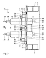
- FIGS. 3 and 4 differs from that 1 and 2 only in that the tool spindles 34, 35 in the z direction are slidably guided on the y-slide 25, while the Workpiece carriers 53, 54 are designed to be non-displaceable in the z direction.
- the tool spindles 34, 35 are part of largely enveloping quills 55, 56. These sleeves 55, 56 are on z-guide rails by means of z-guide carriages 57 58 supported, each in a tool spindle carrier 59, 60 are arranged. These tool spindle supports 59, 60 protrude from the y-slide 25 like boom into the interior 6 of the stand 1. You are connected to one another there by means of a stiffening 61. To the Tool spindle supports 59, 60 are attached to z-motors 62, 63 by means of of which the quills 55, 56 in which contain the tool spindles 34, 35 z direction are driven.
Landscapes
- Engineering & Computer Science (AREA)
- Mechanical Engineering (AREA)
- Machine Tool Units (AREA)
Abstract
Description
- Fig. 1
- eine Teil-Draufsicht auf ein erstes Ausführungsbeispiel einer Doppelspindel-Werkzeugmaschine gemäß dem Sichtpfeil I in Fig. 2,
- Fig. 2
- eine Stirnansicht der Werkzeugmaschine entsprechend dem Sichtpfeil II in Fig. 1,
- Fig. 3
- eine Teil-Draufsicht auf ein zweites Ausführungsbeispiel einer Doppelspindel-Werkzeugmaschine entsprechend dem Sichtpfeil III in Fig. 4 und
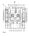
- Fig. 4
- eine Stirnansicht der Werkzeugmaschine entsprechend dem Sichtpfeil IV in Fig. 3.
Die Werkzeugspindeln 34, 35 sind jeweils um eine sich in z-Richtung erstreckende Achse 36, 37 mittels jeweils eines Antriebsmotors 38 antreibbar. Die Werkzeugspindeln 34, 35 können an ihrer dem Arbeitsraum zugewandten Seite jeweils ein spanendes Werkzeug 39 aufnehmen. Die Werkzeugspindeln 34, 35 sind in x- und y-Richtung relativ zueinander ortsfest auf dem y-Schlitten 25 angebracht und beim Ausführungsbeispiel nach den Fig. 1 und 2 in z-Richtung unverschiebbar ausgebildet.
Claims (3)
- Doppelspindel-Werkzeugmaschine,dadurch gekennzeichnet, dass der x-Schlitten (10) je eine seitliche y-Strebe (11, 12) und eine mittlere y-Strebe (15) aufweist,mit einem rahmenartigen Ständer (1),mit einem am Ständer (1) in einer x-Richtung verschiebbar geführten, rahmenartigen x-Schlitten (10),mit einem am x-Schlitten (10) in einer y-Richtung verschiebbaren y-Schlitten (25),mit zwei auf dem y-Schlitten (25) angeordneten Werkzeugspindeln (34, 35) zur Aufnahme von Werkzeugen (39) zur Bearbeitung von in einem Arbeitsraum (7) befindlichen Werkstücken undmit mindestens einem im Arbeitsraum (7) angeordneten Werkstück-Träger (53, 54) zur Aufnahme der Werkstücke,
dass auf den y-Streben (11, 12, 15) je eine seitliche y-Führungs-Schiene (26, 27) bzw. eine mittlere y-Führungs-Schiene (28) angebracht sind und
dass der y-Schlitten (25) auf den y-Führungs-Schienen (26, 27, 28) mittels je mindestens zwei seitlichen y-Führungs-Wagen (29, 30) bzw. mindestens einem mittleren y-Führungs-Wagen (31) geführt ist. - Doppelspindel-Werkzeugmaschine nach Anspruch 1, dadurch gekennzeichnet, dass am Ständer (1) eine obere und eine untere x-Führungs-Schiene (18, 19) angebracht sind und
dass der x-Schlitten (10) auf den x-Führungs-Schienen (18, 19) mittels je zwei seitlichen x-Führungs-Wagen (20, 21) und mittels je eines mittleren x-Führungs-Wagens (22) geführt ist. - Doppelspindel-Werkzeugmaschine nach Anspruch 1 oder 2, dadurch gekennzeichnet, dass die Werkzeugspindeln (34, 35) auf dem y-Schlitten (25) in z-Richtung mittels Werkzeugspindel-Trägern (59, 69) verschiebbar abgestützt sind und
dass die Werkzeugspindel-Träger (59, 60) mittels mindestens einer Versteifung (61) miteinander verbunden sind.
Priority Applications (3)
| Application Number | Priority Date | Filing Date | Title |
|---|---|---|---|
| ES03011277T ES2300521T3 (es) | 2003-05-17 | 2003-05-17 | Maquina herramienta de doble husillo. |
| DE50309411T DE50309411D1 (de) | 2003-05-17 | 2003-05-17 | Doppelspindel-Werkzeugmaschine |
| EP20030011277 EP1479475B1 (de) | 2003-05-17 | 2003-05-17 | Doppelspindel-Werkzeugmaschine |
Applications Claiming Priority (1)
| Application Number | Priority Date | Filing Date | Title |
|---|---|---|---|
| EP20030011277 EP1479475B1 (de) | 2003-05-17 | 2003-05-17 | Doppelspindel-Werkzeugmaschine |
Publications (2)
| Publication Number | Publication Date |
|---|---|
| EP1479475A1 true EP1479475A1 (de) | 2004-11-24 |
| EP1479475B1 EP1479475B1 (de) | 2008-03-19 |
Family
ID=33040947
Family Applications (1)
| Application Number | Title | Priority Date | Filing Date |
|---|---|---|---|
| EP20030011277 Expired - Lifetime EP1479475B1 (de) | 2003-05-17 | 2003-05-17 | Doppelspindel-Werkzeugmaschine |
Country Status (3)
| Country | Link |
|---|---|
| EP (1) | EP1479475B1 (de) |
| DE (1) | DE50309411D1 (de) |
| ES (1) | ES2300521T3 (de) |
Cited By (7)
| Publication number | Priority date | Publication date | Assignee | Title |
|---|---|---|---|---|
| US20160193669A1 (en) * | 2015-01-06 | 2016-07-07 | Feng-Tien Chen | Cnc dual-spindle transmission device |
| CN108480664A (zh) * | 2018-05-30 | 2018-09-04 | 邹善福 | 一种双主轴数控加工机床 |
| CN108714788A (zh) * | 2018-08-13 | 2018-10-30 | 东莞泽鑫数控机床有限公司 | 一种双主轴车铣复合数控机床 |
| CN110270848A (zh) * | 2018-03-15 | 2019-09-24 | 艾格玛科技股份有限公司 | 双机头工具机 |
| CN111660116A (zh) * | 2019-03-07 | 2020-09-15 | 百正创新科技股份有限公司 | Cnc双主轴传动装置 |
| CN113118873A (zh) * | 2021-04-13 | 2021-07-16 | 广东普锐斯智能设备有限公司 | 一种动梁双头型材加工机的结构 |
| CN114211284A (zh) * | 2021-12-22 | 2022-03-22 | 浙江劲帆机床科技有限公司 | 一种双主轴钻攻中心 |
Citations (3)
| Publication number | Priority date | Publication date | Assignee | Title |
|---|---|---|---|---|
| JPS60201847A (ja) * | 1984-03-26 | 1985-10-12 | Mitsubishi Electric Corp | 電気加工機の移動台移動機構 |
| US5611137A (en) * | 1994-11-19 | 1997-03-18 | Maschinenfabrik Berthold Hermle Ag | Machine tool, more particularly for drilling and milling |
| US20010008862A1 (en) * | 1999-04-19 | 2001-07-19 | Gorka Gorrochategui | Machine for drilling oil-holes in crankshafts and its process |
-
2003
- 2003-05-17 ES ES03011277T patent/ES2300521T3/es not_active Expired - Lifetime
- 2003-05-17 EP EP20030011277 patent/EP1479475B1/de not_active Expired - Lifetime
- 2003-05-17 DE DE50309411T patent/DE50309411D1/de not_active Expired - Lifetime
Patent Citations (3)
| Publication number | Priority date | Publication date | Assignee | Title |
|---|---|---|---|---|
| JPS60201847A (ja) * | 1984-03-26 | 1985-10-12 | Mitsubishi Electric Corp | 電気加工機の移動台移動機構 |
| US5611137A (en) * | 1994-11-19 | 1997-03-18 | Maschinenfabrik Berthold Hermle Ag | Machine tool, more particularly for drilling and milling |
| US20010008862A1 (en) * | 1999-04-19 | 2001-07-19 | Gorka Gorrochategui | Machine for drilling oil-holes in crankshafts and its process |
Non-Patent Citations (1)
| Title |
|---|
| PATENT ABSTRACTS OF JAPAN vol. 010, no. 051 (M - 457) 28 February 1986 (1986-02-28) * |
Cited By (10)
| Publication number | Priority date | Publication date | Assignee | Title |
|---|---|---|---|---|
| US20160193669A1 (en) * | 2015-01-06 | 2016-07-07 | Feng-Tien Chen | Cnc dual-spindle transmission device |
| US9610668B2 (en) * | 2015-01-06 | 2017-04-04 | Feng-Tien Chen | CNC dual-spindle transmission device |
| CN110270848A (zh) * | 2018-03-15 | 2019-09-24 | 艾格玛科技股份有限公司 | 双机头工具机 |
| CN110270848B (zh) * | 2018-03-15 | 2021-04-16 | 艾格玛科技股份有限公司 | 双机头工具机 |
| CN108480664A (zh) * | 2018-05-30 | 2018-09-04 | 邹善福 | 一种双主轴数控加工机床 |
| CN108714788A (zh) * | 2018-08-13 | 2018-10-30 | 东莞泽鑫数控机床有限公司 | 一种双主轴车铣复合数控机床 |
| CN108714788B (zh) * | 2018-08-13 | 2023-09-12 | 东莞泽鑫数控机床有限公司 | 一种双主轴车铣复合数控机床 |
| CN111660116A (zh) * | 2019-03-07 | 2020-09-15 | 百正创新科技股份有限公司 | Cnc双主轴传动装置 |
| CN113118873A (zh) * | 2021-04-13 | 2021-07-16 | 广东普锐斯智能设备有限公司 | 一种动梁双头型材加工机的结构 |
| CN114211284A (zh) * | 2021-12-22 | 2022-03-22 | 浙江劲帆机床科技有限公司 | 一种双主轴钻攻中心 |
Also Published As
| Publication number | Publication date |
|---|---|
| DE50309411D1 (de) | 2008-04-30 |
| EP1479475B1 (de) | 2008-03-19 |
| ES2300521T3 (es) | 2008-06-16 |
Similar Documents
| Publication | Publication Date | Title |
|---|---|---|
| EP2190625B1 (de) | Werkzeugmaschine mit zwei schlitten und einem werkzeug-magazin | |
| EP0452735B1 (de) | Bearbeitungszentrum | |
| EP1291122B1 (de) | Fräs- und Bohrbearbeitungszentrum | |
| EP1882544B1 (de) | Fräs- und Bohrmaschine | |
| EP1294531B1 (de) | Anlage zur bearbeitung von werkstücken mit wenigstens einer werkzeug-maschine | |
| EP1419851B1 (de) | Werkzeugmaschine mit Arbeitsspindel auf einer Tripoden-Einheit | |
| EP1402991A2 (de) | Werkzeugmaschine mit einem auf zwei Führungen mit insgesamt drei Auflagern verfahrbarem Fahrständer | |
| EP1585617A1 (de) | Doppelspindel-werkzeugmaschine | |
| DE4015570A1 (de) | Werkzeugmaschine, insbesondere vertikal-schleifmaschine und verfahren zum bearbeiten von werkstuecken mit dieser maschine | |
| EP0928235B1 (de) | Werkzeugmaschine zur spanenden bearbeitung mit horizontal angeordneter arbeitsspindel | |
| EP1479475A1 (de) | Doppelspindel-Werkzeugmaschine | |
| DE102005038877A1 (de) | Werkzeugmaschine | |
| DE102004012385B3 (de) | Werkzeugmaschine mit hängendem Werkzeugrevolver | |
| EP1137508B1 (de) | Werkzeugmaschine mit horizontal angeordneter arbeitsspindel | |
| EP1137509B1 (de) | Werkzeugmaschine mit horizontaler arbeitsspindel | |
| DE19830391A1 (de) | Fräsmaschine mit rotierend antreibbarer Werkzeugspindel | |
| DE602004002682T2 (de) | Tisch zur vorbereitung eines werkstücks vor einer bearbeitung in einer nc-maschine | |
| DE3824572C2 (de) | ||
| EP1609562B1 (de) | Horizontale Werkzeugmaschine mit zwei vertikalen miteinander verbundenen Rahmen | |
| DE3742042C1 (de) | Maschinenbett fuer eine Drehmaschine mit axial verschiebbarem Spindelstock | |
| DE708362C (de) | Maschinengestell fuer selbsttaetige einspindlige Revolverdrehbaenke | |
| DE3414886C1 (de) | Werkzeugmaschine | |
| DE102006048896B3 (de) | Werkzeugmaschine | |
| DE102015115542A1 (de) | Werkzeugmaschine mit einer Funktionsbaugruppe | |
| DE3730622A1 (de) | Fraesmaschine |
Legal Events
| Date | Code | Title | Description |
|---|---|---|---|
| PUAI | Public reference made under article 153(3) epc to a published international application that has entered the european phase |
Free format text: ORIGINAL CODE: 0009012 |
|
| AK | Designated contracting states |
Kind code of ref document: A1 Designated state(s): AT BE BG CH CY CZ DE DK EE ES FI FR GB GR HU IE IT LI LU MC NL PT RO SE SI SK TR |
|
| AX | Request for extension of the european patent |
Extension state: AL LT LV MK |
|
| 17P | Request for examination filed |
Effective date: 20041109 |
|
| AKX | Designation fees paid |
Designated state(s): CZ DE ES FR IT |
|
| 17Q | First examination report despatched |
Effective date: 20061020 |
|
| GRAP | Despatch of communication of intention to grant a patent |
Free format text: ORIGINAL CODE: EPIDOSNIGR1 |
|
| GRAS | Grant fee paid |
Free format text: ORIGINAL CODE: EPIDOSNIGR3 |
|
| GRAA | (expected) grant |
Free format text: ORIGINAL CODE: 0009210 |
|
| AK | Designated contracting states |
Kind code of ref document: B1 Designated state(s): CZ DE ES FR IT |
|
| REF | Corresponds to: |
Ref document number: 50309411 Country of ref document: DE Date of ref document: 20080430 Kind code of ref document: P |
|
| REG | Reference to a national code |
Ref country code: ES Ref legal event code: FG2A Ref document number: 2300521 Country of ref document: ES Kind code of ref document: T3 |
|
| PLBE | No opposition filed within time limit |
Free format text: ORIGINAL CODE: 0009261 |
|
| STAA | Information on the status of an ep patent application or granted ep patent |
Free format text: STATUS: NO OPPOSITION FILED WITHIN TIME LIMIT |
|
| 26N | No opposition filed |
Effective date: 20081222 |
|
| REG | Reference to a national code |
Ref country code: DE Ref legal event code: R081 Ref document number: 50309411 Country of ref document: DE Owner name: MAG IAS GMBH, DE Free format text: FORMER OWNER: CROSS HUELLER GMBH, 71636 LUDWIGSBURG, DE Effective date: 20110223 |
|
| PGFP | Annual fee paid to national office [announced via postgrant information from national office to epo] |
Ref country code: CZ Payment date: 20120509 Year of fee payment: 10 |
|
| PGFP | Annual fee paid to national office [announced via postgrant information from national office to epo] |
Ref country code: IT Payment date: 20120523 Year of fee payment: 10 |
|
| PGFP | Annual fee paid to national office [announced via postgrant information from national office to epo] |
Ref country code: ES Payment date: 20120525 Year of fee payment: 10 |
|
| PG25 | Lapsed in a contracting state [announced via postgrant information from national office to epo] |
Ref country code: CZ Free format text: LAPSE BECAUSE OF NON-PAYMENT OF DUE FEES Effective date: 20130517 |
|
| PG25 | Lapsed in a contracting state [announced via postgrant information from national office to epo] |
Ref country code: IT Free format text: LAPSE BECAUSE OF NON-PAYMENT OF DUE FEES Effective date: 20130517 |
|
| REG | Reference to a national code |
Ref country code: ES Ref legal event code: FD2A Effective date: 20140606 |
|
| PG25 | Lapsed in a contracting state [announced via postgrant information from national office to epo] |
Ref country code: ES Free format text: LAPSE BECAUSE OF NON-PAYMENT OF DUE FEES Effective date: 20130518 |
|
| REG | Reference to a national code |
Ref country code: FR Ref legal event code: PLFP Year of fee payment: 14 |
|
| REG | Reference to a national code |
Ref country code: FR Ref legal event code: PLFP Year of fee payment: 15 |
|
| REG | Reference to a national code |
Ref country code: FR Ref legal event code: PLFP Year of fee payment: 16 |
|
| PGFP | Annual fee paid to national office [announced via postgrant information from national office to epo] |
Ref country code: FR Payment date: 20220523 Year of fee payment: 20 Ref country code: DE Payment date: 20220519 Year of fee payment: 20 |
|
| REG | Reference to a national code |
Ref country code: DE Ref legal event code: R071 Ref document number: 50309411 Country of ref document: DE |
|
| P01 | Opt-out of the competence of the unified patent court (upc) registered |
Effective date: 20230522 |