EP1478040B1 - Electrochemical device and electrode active material for electrochemical device - Google Patents
Electrochemical device and electrode active material for electrochemical device Download PDFInfo
- Publication number
- EP1478040B1 EP1478040B1 EP04252356A EP04252356A EP1478040B1 EP 1478040 B1 EP1478040 B1 EP 1478040B1 EP 04252356 A EP04252356 A EP 04252356A EP 04252356 A EP04252356 A EP 04252356A EP 1478040 B1 EP1478040 B1 EP 1478040B1
- Authority
- EP
- European Patent Office
- Prior art keywords
- group
- active material
- atom
- compound
- electrode active
- Prior art date
- Legal status (The legal status is an assumption and is not a legal conclusion. Google has not performed a legal analysis and makes no representation as to the accuracy of the status listed.)
- Expired - Fee Related
Links
- 239000007772 electrode material Substances 0.000 title claims description 38
- 150000001875 compounds Chemical class 0.000 claims description 122
- 125000001931 aliphatic group Chemical group 0.000 claims description 30
- 229910052744 lithium Inorganic materials 0.000 claims description 30
- WHXSMMKQMYFTQS-UHFFFAOYSA-N Lithium Chemical compound [Li] WHXSMMKQMYFTQS-UHFFFAOYSA-N 0.000 claims description 25
- 239000003792 electrolyte Substances 0.000 claims description 21
- 239000002131 composite material Substances 0.000 claims description 19
- 125000004435 hydrogen atom Chemical group [H]* 0.000 claims description 19
- 229910052717 sulfur Inorganic materials 0.000 claims description 18
- 125000004122 cyclic group Chemical group 0.000 claims description 17
- 239000007773 negative electrode material Substances 0.000 claims description 16
- 229920000642 polymer Polymers 0.000 claims description 16
- 229910052757 nitrogen Inorganic materials 0.000 claims description 15
- 238000006479 redox reaction Methods 0.000 claims description 15
- 125000004434 sulfur atom Chemical group 0.000 claims description 14
- 125000004433 nitrogen atom Chemical group N* 0.000 claims description 13
- 125000004430 oxygen atom Chemical group O* 0.000 claims description 13
- 125000004093 cyano group Chemical group *C#N 0.000 claims description 12
- 125000000449 nitro group Chemical group [O-][N+](*)=O 0.000 claims description 12
- XUIMIQQOPSSXEZ-UHFFFAOYSA-N Silicon Chemical group [Si] XUIMIQQOPSSXEZ-UHFFFAOYSA-N 0.000 claims description 11
- 150000001768 cations Chemical class 0.000 claims description 11
- 125000002496 methyl group Chemical group [H]C([H])([H])* 0.000 claims description 11
- 229910052710 silicon Inorganic materials 0.000 claims description 11
- OKTJSMMVPCPJKN-UHFFFAOYSA-N Carbon Chemical compound [C] OKTJSMMVPCPJKN-UHFFFAOYSA-N 0.000 claims description 10
- 125000003277 amino group Chemical group 0.000 claims description 10
- 125000005843 halogen group Chemical group 0.000 claims description 10
- 125000002887 hydroxy group Chemical group [H]O* 0.000 claims description 10
- 239000000463 material Substances 0.000 claims description 10
- 125000000018 nitroso group Chemical group N(=O)* 0.000 claims description 10
- 125000004437 phosphorous atom Chemical group 0.000 claims description 10
- 229910052698 phosphorus Inorganic materials 0.000 claims description 10
- 239000007774 positive electrode material Substances 0.000 claims description 10
- 239000002904 solvent Substances 0.000 claims description 10
- ZOXJGFHDIHLPTG-UHFFFAOYSA-N Boron Chemical group [B] ZOXJGFHDIHLPTG-UHFFFAOYSA-N 0.000 claims description 9
- 229910052796 boron Inorganic materials 0.000 claims description 9
- 150000004767 nitrides Chemical class 0.000 claims description 9
- GWEVSGVZZGPLCZ-UHFFFAOYSA-N Titan oxide Chemical compound O=[Ti]=O GWEVSGVZZGPLCZ-UHFFFAOYSA-N 0.000 claims description 7
- 150000001450 anions Chemical class 0.000 claims description 7
- 229910001416 lithium ion Inorganic materials 0.000 claims description 7
- 229910052751 metal Inorganic materials 0.000 claims description 7
- 239000002184 metal Substances 0.000 claims description 7
- OGIDPMRJRNCKJF-UHFFFAOYSA-N titanium oxide Inorganic materials [Ti]=O OGIDPMRJRNCKJF-UHFFFAOYSA-N 0.000 claims description 7
- 239000003575 carbonaceous material Substances 0.000 claims description 5
- 239000004020 conductor Substances 0.000 claims description 5
- NAWXUBYGYWOOIX-SFHVURJKSA-N (2s)-2-[[4-[2-(2,4-diaminoquinazolin-6-yl)ethyl]benzoyl]amino]-4-methylidenepentanedioic acid Chemical compound C1=CC2=NC(N)=NC(N)=C2C=C1CCC1=CC=C(C(=O)N[C@@H](CC(=C)C(O)=O)C(O)=O)C=C1 NAWXUBYGYWOOIX-SFHVURJKSA-N 0.000 claims description 4
- ATJFFYVFTNAWJD-UHFFFAOYSA-N Tin Chemical compound [Sn] ATJFFYVFTNAWJD-UHFFFAOYSA-N 0.000 claims description 4
- HSFWRNGVRCDJHI-UHFFFAOYSA-N alpha-acetylene Natural products C#C HSFWRNGVRCDJHI-UHFFFAOYSA-N 0.000 claims description 4
- 229910052799 carbon Inorganic materials 0.000 claims description 4
- 229920001197 polyacetylene Polymers 0.000 claims description 4
- HBBGRARXTFLTSG-UHFFFAOYSA-N Lithium ion Chemical compound [Li+] HBBGRARXTFLTSG-UHFFFAOYSA-N 0.000 claims description 2
- 239000003990 capacitor Substances 0.000 claims description 2
- 229910044991 metal oxide Inorganic materials 0.000 claims description 2
- 150000004706 metal oxides Chemical class 0.000 claims description 2
- 125000004432 carbon atom Chemical group C* 0.000 claims 1
- 229920000193 polymethacrylate Polymers 0.000 claims 1
- 238000006243 chemical reaction Methods 0.000 description 35
- 239000000126 substance Substances 0.000 description 27
- 239000011149 active material Substances 0.000 description 26
- 238000012360 testing method Methods 0.000 description 13
- -1 LiCoO2 Chemical class 0.000 description 11
- 238000007599 discharging Methods 0.000 description 8
- 230000008859 change Effects 0.000 description 7
- 239000000203 mixture Substances 0.000 description 7
- 150000002898 organic sulfur compounds Chemical class 0.000 description 7
- 239000000843 powder Substances 0.000 description 7
- 238000005215 recombination Methods 0.000 description 7
- 230000006798 recombination Effects 0.000 description 7
- 238000000034 method Methods 0.000 description 6
- 230000002829 reductive effect Effects 0.000 description 6
- NINIDFKCEFEMDL-UHFFFAOYSA-N Sulfur Chemical compound [S] NINIDFKCEFEMDL-UHFFFAOYSA-N 0.000 description 5
- 239000011230 binding agent Substances 0.000 description 5
- 229920001577 copolymer Polymers 0.000 description 5
- 238000010494 dissociation reaction Methods 0.000 description 5
- 230000005593 dissociations Effects 0.000 description 5
- 238000011156 evaluation Methods 0.000 description 5
- 230000007246 mechanism Effects 0.000 description 5
- 239000000178 monomer Substances 0.000 description 5
- IJGRMHOSHXDMSA-UHFFFAOYSA-N Atomic nitrogen Chemical compound N#N IJGRMHOSHXDMSA-UHFFFAOYSA-N 0.000 description 4
- 125000003118 aryl group Chemical group 0.000 description 4
- 238000003411 electrode reaction Methods 0.000 description 4
- 230000001590 oxidative effect Effects 0.000 description 4
- 238000007789 sealing Methods 0.000 description 4
- 239000011593 sulfur Substances 0.000 description 4
- RYGMFSIKBFXOCR-UHFFFAOYSA-N Copper Chemical compound [Cu] RYGMFSIKBFXOCR-UHFFFAOYSA-N 0.000 description 3
- BWGNESOTFCXPMA-UHFFFAOYSA-N Dihydrogen disulfide Chemical compound SS BWGNESOTFCXPMA-UHFFFAOYSA-N 0.000 description 3
- ZMXDDKWLCZADIW-UHFFFAOYSA-N N,N-Dimethylformamide Chemical compound CN(C)C=O ZMXDDKWLCZADIW-UHFFFAOYSA-N 0.000 description 3
- 125000000217 alkyl group Chemical group 0.000 description 3
- 230000000052 comparative effect Effects 0.000 description 3
- 230000021615 conjugation Effects 0.000 description 3
- 229910052802 copper Inorganic materials 0.000 description 3
- 239000010949 copper Substances 0.000 description 3
- 125000000623 heterocyclic group Chemical group 0.000 description 3
- IDBFBDSKYCUNPW-UHFFFAOYSA-N lithium nitride Chemical compound [Li]N([Li])[Li] IDBFBDSKYCUNPW-UHFFFAOYSA-N 0.000 description 3
- 150000002739 metals Chemical class 0.000 description 3
- 150000002894 organic compounds Chemical class 0.000 description 3
- 229920001343 polytetrafluoroethylene Polymers 0.000 description 3
- 239000004810 polytetrafluoroethylene Substances 0.000 description 3
- 150000003839 salts Chemical class 0.000 description 3
- 239000007784 solid electrolyte Substances 0.000 description 3
- BQCIDUSAKPWEOX-UHFFFAOYSA-N 1,1-Difluoroethene Chemical compound FC(F)=C BQCIDUSAKPWEOX-UHFFFAOYSA-N 0.000 description 2
- YEJRWHAVMIAJKC-UHFFFAOYSA-N 4-Butyrolactone Chemical compound O=C1CCCO1 YEJRWHAVMIAJKC-UHFFFAOYSA-N 0.000 description 2
- KAKZBPTYRLMSJV-UHFFFAOYSA-N Butadiene Chemical compound C=CC=C KAKZBPTYRLMSJV-UHFFFAOYSA-N 0.000 description 2
- OIFBSDVPJOWBCH-UHFFFAOYSA-N Diethyl carbonate Chemical compound CCOC(=O)OCC OIFBSDVPJOWBCH-UHFFFAOYSA-N 0.000 description 2
- KMTRUDSVKNLOMY-UHFFFAOYSA-N Ethylene carbonate Chemical compound O=C1OCCO1 KMTRUDSVKNLOMY-UHFFFAOYSA-N 0.000 description 2
- DGAQECJNVWCQMB-PUAWFVPOSA-M Ilexoside XXIX Chemical compound C[C@@H]1CC[C@@]2(CC[C@@]3(C(=CC[C@H]4[C@]3(CC[C@@H]5[C@@]4(CC[C@@H](C5(C)C)OS(=O)(=O)[O-])C)C)[C@@H]2[C@]1(C)O)C)C(=O)O[C@H]6[C@@H]([C@H]([C@@H]([C@H](O6)CO)O)O)O.[Na+] DGAQECJNVWCQMB-PUAWFVPOSA-M 0.000 description 2
- 229910011954 Li2.6Co0.4N Inorganic materials 0.000 description 2
- 229910012670 LiTi5O12 Inorganic materials 0.000 description 2
- FYYHWMGAXLPEAU-UHFFFAOYSA-N Magnesium Chemical compound [Mg] FYYHWMGAXLPEAU-UHFFFAOYSA-N 0.000 description 2
- SECXISVLQFMRJM-UHFFFAOYSA-N N-Methylpyrrolidone Chemical compound CN1CCCC1=O SECXISVLQFMRJM-UHFFFAOYSA-N 0.000 description 2
- PXHVJJICTQNCMI-UHFFFAOYSA-N Nickel Chemical compound [Ni] PXHVJJICTQNCMI-UHFFFAOYSA-N 0.000 description 2
- 239000002033 PVDF binder Substances 0.000 description 2
- 229920003171 Poly (ethylene oxide) Polymers 0.000 description 2
- 239000004698 Polyethylene Substances 0.000 description 2
- VYPSYNLAJGMNEJ-UHFFFAOYSA-N Silicium dioxide Chemical compound O=[Si]=O VYPSYNLAJGMNEJ-UHFFFAOYSA-N 0.000 description 2
- PPBRXRYQALVLMV-UHFFFAOYSA-N Styrene Chemical compound C=CC1=CC=CC=C1 PPBRXRYQALVLMV-UHFFFAOYSA-N 0.000 description 2
- WYURNTSHIVDZCO-UHFFFAOYSA-N Tetrahydrofuran Chemical compound C1CCOC1 WYURNTSHIVDZCO-UHFFFAOYSA-N 0.000 description 2
- 239000006230 acetylene black Substances 0.000 description 2
- 229910045601 alloy Inorganic materials 0.000 description 2
- 239000000956 alloy Substances 0.000 description 2
- 229910052782 aluminium Inorganic materials 0.000 description 2
- XAGFODPZIPBFFR-UHFFFAOYSA-N aluminium Chemical compound [Al] XAGFODPZIPBFFR-UHFFFAOYSA-N 0.000 description 2
- PNEYBMLMFCGWSK-UHFFFAOYSA-N aluminium oxide Inorganic materials [O-2].[O-2].[O-2].[Al+3].[Al+3] PNEYBMLMFCGWSK-UHFFFAOYSA-N 0.000 description 2
- QVGXLLKOCUKJST-UHFFFAOYSA-N atomic oxygen Chemical compound [O] QVGXLLKOCUKJST-UHFFFAOYSA-N 0.000 description 2
- 230000015572 biosynthetic process Effects 0.000 description 2
- 230000006866 deterioration Effects 0.000 description 2
- 239000011888 foil Substances 0.000 description 2
- 239000007789 gas Substances 0.000 description 2
- 239000010439 graphite Substances 0.000 description 2
- 229910002804 graphite Inorganic materials 0.000 description 2
- 150000004820 halides Chemical class 0.000 description 2
- 125000005842 heteroatom Chemical group 0.000 description 2
- KWGKDLIKAYFUFQ-UHFFFAOYSA-M lithium chloride Chemical compound [Li+].[Cl-] KWGKDLIKAYFUFQ-UHFFFAOYSA-M 0.000 description 2
- PQXKHYXIUOZZFA-UHFFFAOYSA-M lithium fluoride Chemical compound [Li+].[F-] PQXKHYXIUOZZFA-UHFFFAOYSA-M 0.000 description 2
- 239000011777 magnesium Substances 0.000 description 2
- 229910052749 magnesium Inorganic materials 0.000 description 2
- 239000011159 matrix material Substances 0.000 description 2
- 229910052760 oxygen Inorganic materials 0.000 description 2
- 239000001301 oxygen Substances 0.000 description 2
- 229920003229 poly(methyl methacrylate) Polymers 0.000 description 2
- 229920000573 polyethylene Polymers 0.000 description 2
- 239000004926 polymethyl methacrylate Substances 0.000 description 2
- 229920002981 polyvinylidene fluoride Polymers 0.000 description 2
- 238000005096 rolling process Methods 0.000 description 2
- 229910052814 silicon oxide Inorganic materials 0.000 description 2
- 239000002002 slurry Substances 0.000 description 2
- 229910052708 sodium Inorganic materials 0.000 description 2
- 239000011734 sodium Substances 0.000 description 2
- OQMIRQSWHKCKNJ-UHFFFAOYSA-N 1,1-difluoroethene;1,1,2,3,3,3-hexafluoroprop-1-ene Chemical group FC(F)=C.FC(F)=C(F)C(F)(F)F OQMIRQSWHKCKNJ-UHFFFAOYSA-N 0.000 description 1
- BIGYLAKFCGVRAN-UHFFFAOYSA-N 1,3,4-thiadiazolidine-2,5-dithione Chemical compound S=C1NNC(=S)S1 BIGYLAKFCGVRAN-UHFFFAOYSA-N 0.000 description 1
- WNXJIVFYUVYPPR-UHFFFAOYSA-N 1,3-dioxolane Chemical compound C1COCO1 WNXJIVFYUVYPPR-UHFFFAOYSA-N 0.000 description 1
- NLHHRLWOUZZQLW-UHFFFAOYSA-N Acrylonitrile Chemical compound C=CC#N NLHHRLWOUZZQLW-UHFFFAOYSA-N 0.000 description 1
- 229910000838 Al alloy Inorganic materials 0.000 description 1
- 229910000531 Co alloy Inorganic materials 0.000 description 1
- VGGSQFUCUMXWEO-UHFFFAOYSA-N Ethene Chemical compound C=C VGGSQFUCUMXWEO-UHFFFAOYSA-N 0.000 description 1
- 239000005977 Ethylene Substances 0.000 description 1
- YCKRFDGAMUMZLT-UHFFFAOYSA-N Fluorine atom Chemical class [F] YCKRFDGAMUMZLT-UHFFFAOYSA-N 0.000 description 1
- 241000565357 Fraxinus nigra Species 0.000 description 1
- 101000635799 Homo sapiens Run domain Beclin-1-interacting and cysteine-rich domain-containing protein Proteins 0.000 description 1
- 229910000733 Li alloy Inorganic materials 0.000 description 1
- 229910009295 Li2S-B2S5 Inorganic materials 0.000 description 1
- 229910009311 Li2S-SiS2 Inorganic materials 0.000 description 1
- 229910009340 Li2S—B2S5 Inorganic materials 0.000 description 1
- 229910009165 Li2S—P2O5 Inorganic materials 0.000 description 1
- 229910009225 Li2S—P2S5—GeS2 Inorganic materials 0.000 description 1
- 229910009433 Li2S—SiS2 Inorganic materials 0.000 description 1
- 229910032387 LiCoO2 Inorganic materials 0.000 description 1
- 229910003005 LiNiO2 Inorganic materials 0.000 description 1
- 229910001290 LiPF6 Inorganic materials 0.000 description 1
- 229910002097 Lithium manganese(III,IV) oxide Inorganic materials 0.000 description 1
- MPCRDALPQLDDFX-UHFFFAOYSA-L Magnesium perchlorate Chemical compound [Mg+2].[O-]Cl(=O)(=O)=O.[O-]Cl(=O)(=O)=O MPCRDALPQLDDFX-UHFFFAOYSA-L 0.000 description 1
- 239000004642 Polyimide Substances 0.000 description 1
- 239000004721 Polyphenylene oxide Substances 0.000 description 1
- 239000004743 Polypropylene Substances 0.000 description 1
- ZLMJMSJWJFRBEC-UHFFFAOYSA-N Potassium Chemical compound [K] ZLMJMSJWJFRBEC-UHFFFAOYSA-N 0.000 description 1
- 102100030852 Run domain Beclin-1-interacting and cysteine-rich domain-containing protein Human genes 0.000 description 1
- 229910000676 Si alloy Inorganic materials 0.000 description 1
- BQCADISMDOOEFD-UHFFFAOYSA-N Silver Chemical compound [Ag] BQCADISMDOOEFD-UHFFFAOYSA-N 0.000 description 1
- NIXOWILDQLNWCW-UHFFFAOYSA-M acrylate group Chemical group C(C=C)(=O)[O-] NIXOWILDQLNWCW-UHFFFAOYSA-M 0.000 description 1
- 125000003172 aldehyde group Chemical group 0.000 description 1
- 229910052784 alkaline earth metal Inorganic materials 0.000 description 1
- 125000003342 alkenyl group Chemical group 0.000 description 1
- 125000003545 alkoxy group Chemical group 0.000 description 1
- 125000002521 alkyl halide group Chemical group 0.000 description 1
- 125000004414 alkyl thio group Chemical group 0.000 description 1
- 229910003481 amorphous carbon Inorganic materials 0.000 description 1
- 125000005110 aryl thio group Chemical group 0.000 description 1
- 239000012298 atmosphere Substances 0.000 description 1
- 125000004429 atom Chemical group 0.000 description 1
- 239000006229 carbon black Substances 0.000 description 1
- 239000011203 carbon fibre reinforced carbon Substances 0.000 description 1
- 125000002843 carboxylic acid group Chemical group 0.000 description 1
- 230000003197 catalytic effect Effects 0.000 description 1
- 239000010941 cobalt Substances 0.000 description 1
- GUTLYIVDDKVIGB-UHFFFAOYSA-N cobalt atom Chemical compound [Co] GUTLYIVDDKVIGB-UHFFFAOYSA-N 0.000 description 1
- 239000011231 conductive filler Substances 0.000 description 1
- 229920000547 conjugated polymer Polymers 0.000 description 1
- 239000000470 constituent Substances 0.000 description 1
- 229910052593 corundum Inorganic materials 0.000 description 1
- 229920006037 cross link polymer Polymers 0.000 description 1
- 239000013078 crystal Substances 0.000 description 1
- 125000000753 cycloalkyl group Chemical group 0.000 description 1
- 230000003247 decreasing effect Effects 0.000 description 1
- 238000011161 development Methods 0.000 description 1
- IEJIGPNLZYLLBP-UHFFFAOYSA-N dimethyl carbonate Chemical compound COC(=O)OC IEJIGPNLZYLLBP-UHFFFAOYSA-N 0.000 description 1
- 238000001035 drying Methods 0.000 description 1
- JBTWLSYIZRCDFO-UHFFFAOYSA-N ethyl methyl carbonate Chemical compound CCOC(=O)OC JBTWLSYIZRCDFO-UHFFFAOYSA-N 0.000 description 1
- 229910052731 fluorine Inorganic materials 0.000 description 1
- 239000011737 fluorine Substances 0.000 description 1
- 239000011245 gel electrolyte Substances 0.000 description 1
- PCHJSUWPFVWCPO-UHFFFAOYSA-N gold Chemical compound [Au] PCHJSUWPFVWCPO-UHFFFAOYSA-N 0.000 description 1
- 229910052737 gold Inorganic materials 0.000 description 1
- 239000010931 gold Substances 0.000 description 1
- 230000005484 gravity Effects 0.000 description 1
- HCDGVLDPFQMKDK-UHFFFAOYSA-N hexafluoropropylene Chemical group FC(F)=C(F)C(F)(F)F HCDGVLDPFQMKDK-UHFFFAOYSA-N 0.000 description 1
- 125000002768 hydroxyalkyl group Chemical group 0.000 description 1
- MHCFAGZWMAWTNR-UHFFFAOYSA-M lithium perchlorate Chemical compound [Li+].[O-]Cl(=O)(=O)=O MHCFAGZWMAWTNR-UHFFFAOYSA-M 0.000 description 1
- 229910001486 lithium perchlorate Inorganic materials 0.000 description 1
- 229910001496 lithium tetrafluoroborate Inorganic materials 0.000 description 1
- QSZMZKBZAYQGRS-UHFFFAOYSA-N lithium;bis(trifluoromethylsulfonyl)azanide Chemical compound [Li+].FC(F)(F)S(=O)(=O)[N-]S(=O)(=O)C(F)(F)F QSZMZKBZAYQGRS-UHFFFAOYSA-N 0.000 description 1
- ZJZXSOKJEJFHCP-UHFFFAOYSA-M lithium;thiocyanate Chemical compound [Li+].[S-]C#N ZJZXSOKJEJFHCP-UHFFFAOYSA-M 0.000 description 1
- MCVFFRWZNYZUIJ-UHFFFAOYSA-M lithium;trifluoromethanesulfonate Chemical compound [Li+].[O-]S(=O)(=O)C(F)(F)F MCVFFRWZNYZUIJ-UHFFFAOYSA-M 0.000 description 1
- 238000004519 manufacturing process Methods 0.000 description 1
- CERQOIWHTDAKMF-UHFFFAOYSA-M methacrylate group Chemical group C(C(=C)C)(=O)[O-] CERQOIWHTDAKMF-UHFFFAOYSA-M 0.000 description 1
- WCYWZMWISLQXQU-UHFFFAOYSA-N methyl Chemical compound [CH3] WCYWZMWISLQXQU-UHFFFAOYSA-N 0.000 description 1
- 239000012046 mixed solvent Substances 0.000 description 1
- 238000010295 mobile communication Methods 0.000 description 1
- 229910052759 nickel Inorganic materials 0.000 description 1
- 239000012299 nitrogen atmosphere Substances 0.000 description 1
- 238000005580 one pot reaction Methods 0.000 description 1
- 239000003960 organic solvent Substances 0.000 description 1
- 230000033116 oxidation-reduction process Effects 0.000 description 1
- 238000005691 oxidative coupling reaction Methods 0.000 description 1
- VLTRZXGMWDSKGL-UHFFFAOYSA-M perchlorate Inorganic materials [O-]Cl(=O)(=O)=O VLTRZXGMWDSKGL-UHFFFAOYSA-M 0.000 description 1
- VLTRZXGMWDSKGL-UHFFFAOYSA-N perchloric acid Chemical compound OCl(=O)(=O)=O VLTRZXGMWDSKGL-UHFFFAOYSA-N 0.000 description 1
- 125000001997 phenyl group Chemical group [H]C1=C([H])C([H])=C(*)C([H])=C1[H] 0.000 description 1
- 229920000058 polyacrylate Polymers 0.000 description 1
- 229920002239 polyacrylonitrile Polymers 0.000 description 1
- 229920000767 polyaniline Polymers 0.000 description 1
- 229920000570 polyether Polymers 0.000 description 1
- 229920001721 polyimide Polymers 0.000 description 1
- 238000006116 polymerization reaction Methods 0.000 description 1
- 230000000379 polymerizing effect Effects 0.000 description 1
- 229920001155 polypropylene Polymers 0.000 description 1
- 229920000128 polypyrrole Polymers 0.000 description 1
- 229920000123 polythiophene Polymers 0.000 description 1
- 239000011591 potassium Substances 0.000 description 1
- 229910052700 potassium Inorganic materials 0.000 description 1
- 238000000634 powder X-ray diffraction Methods 0.000 description 1
- 238000003825 pressing Methods 0.000 description 1
- RUOJZAUFBMNUDX-UHFFFAOYSA-N propylene carbonate Chemical compound CC1COC(=O)O1 RUOJZAUFBMNUDX-UHFFFAOYSA-N 0.000 description 1
- 230000005855 radiation Effects 0.000 description 1
- 238000006722 reduction reaction Methods 0.000 description 1
- 229920005989 resin Polymers 0.000 description 1
- 239000011347 resin Substances 0.000 description 1
- 230000027756 respiratory electron transport chain Effects 0.000 description 1
- 239000010703 silicon Substances 0.000 description 1
- 229910052709 silver Inorganic materials 0.000 description 1
- 239000004332 silver Substances 0.000 description 1
- 238000005549 size reduction Methods 0.000 description 1
- 229910001495 sodium tetrafluoroborate Inorganic materials 0.000 description 1
- 239000006104 solid solution Substances 0.000 description 1
- 239000010935 stainless steel Substances 0.000 description 1
- 229910001220 stainless steel Inorganic materials 0.000 description 1
- HXJUTPCZVOIRIF-UHFFFAOYSA-N sulfolane Chemical compound O=S1(=O)CCCC1 HXJUTPCZVOIRIF-UHFFFAOYSA-N 0.000 description 1
- BFKJFAAPBSQJPD-UHFFFAOYSA-N tetrafluoroethene Chemical group FC(F)=C(F)F BFKJFAAPBSQJPD-UHFFFAOYSA-N 0.000 description 1
- YLQBMQCUIZJEEH-UHFFFAOYSA-N tetrahydrofuran Natural products C=1C=COC=1 YLQBMQCUIZJEEH-UHFFFAOYSA-N 0.000 description 1
- 125000004001 thioalkyl group Chemical group 0.000 description 1
- 230000007704 transition Effects 0.000 description 1
- ITMCEJHCFYSIIV-UHFFFAOYSA-M triflate Chemical compound [O-]S(=O)(=O)C(F)(F)F ITMCEJHCFYSIIV-UHFFFAOYSA-M 0.000 description 1
- PPPHYGCRGMTZNA-UHFFFAOYSA-M trifluoromethyl sulfate Chemical compound [O-]S(=O)(=O)OC(F)(F)F PPPHYGCRGMTZNA-UHFFFAOYSA-M 0.000 description 1
- 238000001291 vacuum drying Methods 0.000 description 1
- 229910001845 yogo sapphire Inorganic materials 0.000 description 1
Images
Classifications
-
- H—ELECTRICITY
- H01—ELECTRIC ELEMENTS
- H01M—PROCESSES OR MEANS, e.g. BATTERIES, FOR THE DIRECT CONVERSION OF CHEMICAL ENERGY INTO ELECTRICAL ENERGY
- H01M4/00—Electrodes
- H01M4/02—Electrodes composed of, or comprising, active material
- H01M4/13—Electrodes for accumulators with non-aqueous electrolyte, e.g. for lithium-accumulators; Processes of manufacture thereof
- H01M4/137—Electrodes based on electro-active polymers
-
- H—ELECTRICITY
- H01—ELECTRIC ELEMENTS
- H01G—CAPACITORS; CAPACITORS, RECTIFIERS, DETECTORS, SWITCHING DEVICES OR LIGHT-SENSITIVE DEVICES, OF THE ELECTROLYTIC TYPE
- H01G11/00—Hybrid capacitors, i.e. capacitors having different positive and negative electrodes; Electric double-layer [EDL] capacitors; Processes for the manufacture thereof or of parts thereof
- H01G11/02—Hybrid capacitors, i.e. capacitors having different positive and negative electrodes; Electric double-layer [EDL] capacitors; Processes for the manufacture thereof or of parts thereof using combined reduction-oxidation reactions, e.g. redox arrangement or solion
-
- H—ELECTRICITY
- H01—ELECTRIC ELEMENTS
- H01G—CAPACITORS; CAPACITORS, RECTIFIERS, DETECTORS, SWITCHING DEVICES OR LIGHT-SENSITIVE DEVICES, OF THE ELECTROLYTIC TYPE
- H01G11/00—Hybrid capacitors, i.e. capacitors having different positive and negative electrodes; Electric double-layer [EDL] capacitors; Processes for the manufacture thereof or of parts thereof
- H01G11/22—Electrodes
- H01G11/30—Electrodes characterised by their material
- H01G11/48—Conductive polymers
-
- H—ELECTRICITY
- H01—ELECTRIC ELEMENTS
- H01M—PROCESSES OR MEANS, e.g. BATTERIES, FOR THE DIRECT CONVERSION OF CHEMICAL ENERGY INTO ELECTRICAL ENERGY
- H01M4/00—Electrodes
- H01M4/02—Electrodes composed of, or comprising, active material
- H01M4/36—Selection of substances as active materials, active masses, active liquids
- H01M4/60—Selection of substances as active materials, active masses, active liquids of organic compounds
- H01M4/602—Polymers
- H01M4/606—Polymers containing aromatic main chain polymers
- H01M4/608—Polymers containing aromatic main chain polymers containing heterocyclic rings
-
- H—ELECTRICITY
- H01—ELECTRIC ELEMENTS
- H01G—CAPACITORS; CAPACITORS, RECTIFIERS, DETECTORS, SWITCHING DEVICES OR LIGHT-SENSITIVE DEVICES, OF THE ELECTROLYTIC TYPE
- H01G11/00—Hybrid capacitors, i.e. capacitors having different positive and negative electrodes; Electric double-layer [EDL] capacitors; Processes for the manufacture thereof or of parts thereof
- H01G11/22—Electrodes
- H01G11/30—Electrodes characterised by their material
- H01G11/46—Metal oxides
-
- H—ELECTRICITY
- H01—ELECTRIC ELEMENTS
- H01M—PROCESSES OR MEANS, e.g. BATTERIES, FOR THE DIRECT CONVERSION OF CHEMICAL ENERGY INTO ELECTRICAL ENERGY
- H01M4/00—Electrodes
- H01M4/02—Electrodes composed of, or comprising, active material
- H01M2004/026—Electrodes composed of, or comprising, active material characterised by the polarity
- H01M2004/027—Negative electrodes
-
- H—ELECTRICITY
- H01—ELECTRIC ELEMENTS
- H01M—PROCESSES OR MEANS, e.g. BATTERIES, FOR THE DIRECT CONVERSION OF CHEMICAL ENERGY INTO ELECTRICAL ENERGY
- H01M4/00—Electrodes
- H01M4/02—Electrodes composed of, or comprising, active material
- H01M2004/026—Electrodes composed of, or comprising, active material characterised by the polarity
- H01M2004/028—Positive electrodes
-
- H—ELECTRICITY
- H01—ELECTRIC ELEMENTS
- H01M—PROCESSES OR MEANS, e.g. BATTERIES, FOR THE DIRECT CONVERSION OF CHEMICAL ENERGY INTO ELECTRICAL ENERGY
- H01M50/00—Constructional details or processes of manufacture of the non-active parts of electrochemical cells other than fuel cells, e.g. hybrid cells
- H01M50/10—Primary casings, jackets or wrappings of a single cell or a single battery
- H01M50/102—Primary casings, jackets or wrappings of a single cell or a single battery characterised by their shape or physical structure
- H01M50/109—Primary casings, jackets or wrappings of a single cell or a single battery characterised by their shape or physical structure of button or coin shape
-
- Y—GENERAL TAGGING OF NEW TECHNOLOGICAL DEVELOPMENTS; GENERAL TAGGING OF CROSS-SECTIONAL TECHNOLOGIES SPANNING OVER SEVERAL SECTIONS OF THE IPC; TECHNICAL SUBJECTS COVERED BY FORMER USPC CROSS-REFERENCE ART COLLECTIONS [XRACs] AND DIGESTS
- Y02—TECHNOLOGIES OR APPLICATIONS FOR MITIGATION OR ADAPTATION AGAINST CLIMATE CHANGE
- Y02E—REDUCTION OF GREENHOUSE GAS [GHG] EMISSIONS, RELATED TO ENERGY GENERATION, TRANSMISSION OR DISTRIBUTION
- Y02E60/00—Enabling technologies; Technologies with a potential or indirect contribution to GHG emissions mitigation
- Y02E60/10—Energy storage using batteries
-
- Y—GENERAL TAGGING OF NEW TECHNOLOGICAL DEVELOPMENTS; GENERAL TAGGING OF CROSS-SECTIONAL TECHNOLOGIES SPANNING OVER SEVERAL SECTIONS OF THE IPC; TECHNICAL SUBJECTS COVERED BY FORMER USPC CROSS-REFERENCE ART COLLECTIONS [XRACs] AND DIGESTS
- Y02—TECHNOLOGIES OR APPLICATIONS FOR MITIGATION OR ADAPTATION AGAINST CLIMATE CHANGE
- Y02E—REDUCTION OF GREENHOUSE GAS [GHG] EMISSIONS, RELATED TO ENERGY GENERATION, TRANSMISSION OR DISTRIBUTION
- Y02E60/00—Enabling technologies; Technologies with a potential or indirect contribution to GHG emissions mitigation
- Y02E60/13—Energy storage using capacitors
Definitions
- Organic compounds are so light as to have a specific gravity of about 1 g/cm 3 , which is lighter than lithium cobaltate currently in use as a material for lithium secondary batteries.
- the use of organic compounds as electrode materials therefore allows fabrication of batteries lighter in weight and higher in capacity than conventional batteries.
- U.S. Patent No. 4,833,048 and Japanese Patent No. 2,715,778 have proposed lithium secondary batteries where an organosulfur compound having a disulfide bond is used as an electrode material.
- Such an organosulfur compound is most simply represented by: M + - - S-R-S - -M + .
- R represents an aliphatic group or an aromatic group
- S represents sulfur
- M + represents a proton or a metal cation.
- the above compounds are bonded to each other via the S-S bond through an electrochemical oxidative reaction to give a polymer with a structure of M + - - S-S-S-R-S-S-R-S -M + .
- the polymer thus produced returns to the original monomers through an electrochemical reduction reaction. In lithium secondary batteries, this reaction is applied to the charging/discharging reaction in secondary batteries.
- an object of the present invention is to improve a cycle characteristic of a lightweight electrochemical device having high energy density.
- US2002/0027415 A1 discloses a dithiafulvene derivative represented by Formula (1): wherein R 1 and R 2 represent an alkyl group, an aryl group or a heterocyclic group; R 3 to R 6 represent a hydrogen atom, an alkyl group, an alkenyl group, an alkylthio group, an arylthio group, an aryl group or a heterocyclic group; and when R 3 to R 6 are an aryl group or a heterocyclic group adjacent to each other, they may be condensed to each other.
- this derivative is for use in an organic electroluminescent device.
- An electrochemical device of the present invention comprises a positive electrode, a negative electrode and an electrolyte, wherein at least one of said positive electrode and said negative electrode includes a compound having a structure represented by the general formula (1a): where X is a sulfur atom or an oxygen atom; each of R 1 to R 4 is independently a methyl group, a linear or cyclic aliphatic group, a hydrogen atom, a hydroxyl group, a cyano group, an amino group, a nitro group or a nitroso group; each of R 5 and R 6 is independently a linear or cyclic aliphatic group or a hydrogen atom; said aliphatic group includes at least one selected from the group consisting of an oxygen atom, a nitrogen atom, a sulfur atom, a silicon atom, a phosphorus atom, a boron atom and a halogen atom.
- X is a sulfur atom or an oxygen atom
- each of R 1 to R 4 is independently
- a further electrochemical device of the present invention comprises a positive electrode, a negative electrode and an electrolyte, wherein at least one of said positive electrode and said negative electrode includes a compound having a structure represented by the general formula (1b): where X is a nitrogen atom; each of R 1 to R 4 is independently a methyl group, a linear or cyclic aliphatic group, a hydrogen atom, a hydroxyl group, a cyano group, an amino group, a nitro group or a nitroso group; each of R 5 and R 6 is independently a linear or cyclic aliphatic group or a hydrogen atom; said aliphatic group includes at least one selected from the group consisting of an oxygen atom, a nitrogen atom, a sulfur atom, a silicon atom, a phosphorus atom, a boron atom and a halogen atom.
- each X in the general formula (1a) or (1b) is the same, it is contemplated that each X may be independently selected from sulfur, nitrogen or oxygen.
- a further electrochemical device of the present invention comprises a positive electrode, a negative electrode and an electrolyte, wherein at least one of said positive electrode and said negative electrode includes a compound represented by the general formula (2): where each of R 1 to R 4 and R 7 to R 10 is independently a methyl group, a linear or cyclic aliphatic group, a hydrogen atom, a hydroxyl group, a cyano group, an amino group, a nitro group or a nitroso group; said aliphatic group includes at least one selected from the group consisting of an oxygen atom, a nitrogen atom, a sulfur atom, a silicon atom, a phosphorus atom, a boron atom and a halogen atom.
- the compound be a polymer compound having more than one structure represented by the general formula (1a), (1b) or (2).
- the electrolyte comprises a solvent, and an anion and a cation that diffuse in the solvent, and the compound be capable of forming a coordinate bond with the cation through an oxidation-reduction reaction.
- the cation be a lithium ion.
- the electrolyte comprises a solvent, and an anion and a cation that diffuse in the solvent, and the compound be capable of forming a coordinate bond with the anion through an oxidation-reduction reaction.
- the positive electrode includes the compound as a positive electrode active material
- the negative electrode include a carbon material as a negative electrode active material
- the positive electrode includes the compound as a positive electrode active material
- the negative electrode include, as a negative electrode active material, at least one selected from the group consisting of a lithium metal, a lithium-containing composite nitride, a lithium-containing composite titanium oxide, a silicon-based alloy, and a silicon oxide.
- An electrochemical device of the present invention provides an electric energy by converting an electron transfer through an oxidation-reduction reaction into the electric energy, and comprises a positive electrode, a negative electrode and an electrolyte. At least one of the positive electrode and the negative electrode includes a compound having a structure represented by the general formula (1a), (1b) or (2).
- General formula (1a) is: where X is a sulfur atom or an oxygen atom; each of R 1 to R 4 is independently a methyl group, a linear or cyclic aliphatic group, a hydrogen atom, a hydroxyl group, a cyano group, an amino group, a nitro group or a nitroso group; each of R 5 and R 6 is independently a linear or cyclic aliphatic group or a hydrogen atom; the aliphatic group includes at least one selected from the group consisting of an oxygen atom, a nitrogen atom, a sulfur atom, a silicon atom, a phosphorus atom, a boron atom and a halogen atom.
- General formula (1b) is: where X is a nitrogen atom; each of R 1 to R 4 is independently a methyl group, a linear or cyclic aliphatic group, a hydrogen atom, a hydroxyl group, a cyano group, an amino group, a nitro group or a nitroso group; each of R 5 and R 6 is independently a linear or cyclic aliphatic group or a hydrogen atom; said aliphatic group includes at least ona selected from the group consisting of an oxygen atom, a nitrogen atom, a sulfur atom, silicon atom, a phosphorus atom, a boron atom and a halogen atom.
- each of R 1 to R 4 and R 7 to R 10 is independently a methyl group, a linear or cyclic aliphatic group, a hydrogen atom, a hydroxyl group, a cyano group, an amino group, a nitro group or a nitroso group; said aliphatic group includes at least one selected from the group consisting of an oxygen atom, a nitrogen atom, a sulfur atom, a silicon atom, a phosphorus atom, a baron atom and a halogen atom.
- the compound may be referred to as "active material compound".
- the active material compound as an electrode active material brings about an oxidation-reduction reaction within the battery to give and receive electrons.
- the active material compound can cause an oxidation-reduction reaction without any significant structural change therein.
- the mechanism is described below.
- the active material compound has a structural symmetry and a planar structure. Further, the active material compound has a carbon-carbon double bond at the center of the molecule thereof, and cyclic structures, including hetero atoms such as sulfur and oxygen. The hetero atoms have lone electron pairs. This causes formation of conjugation by ⁇ electrons on the molecule. In the ⁇ -electron conjugation portion, having spread over the molecule, electrons can be given and received. This giving and receiving of the electrons proceed as the oxidation-reduction reaction of the active material compound.
- a reductive reaction for example, the active material compound is reduced and cations in an electrolyte are coordinated in the reduced molecule.
- a subsequent oxidative reaction for example, the cations having been coordinated in the active material compound are eliminated. This reaction is usable as a battery reaction.
- the compound whose oxidation-reduction reaction occurs in the ⁇ -electron conjugation portion having spread over the molecule, is used as the electrode active material.
- the above reaction mechanism there occurs no significant change of the skeletal structure of the active material through the oxidation-redaction reaction. Accordingly, deterioration in structure of the active material, attributed to repetition of the oxidation-reduction reactions, is suppressed so that an excellent charge/discharge cycle characteristic can be obtained.
- the reaction is expected to proceed more rapidly than dissociation and recombination reaction cause by a conventional organosulfur compounds.
- the reaction rate becomes faster, a rate characteristic excellent as a battery characteristic can be expected, and it is thus advantageous for rapid charge/discharge.
- a compound represented by the chemical formula (3): and a compound represented by the chemical formula (4): are preferred. Since those compounds have the smallest molecular weight among the compounds represented by the general formulae (1a) and (1b), the active materials thereof have the highest energy density, and hence an electrochemical device having high energy density can be obtained.
- the active material compound be a compound represented by the general formula (2) : where each of R 1 to R 4 and R 7 to R 10 is independently a linear or cyclic aliphatic group, a hydrogen atom, a hydroxyl group, a cyano group, an amino group, a nitro group or a nitroso group; the aliphatic group includes at least one selected from the group consisting of an oxygen atom, a nitrogen atom, a sulfur atom, a silicon atom, a phosphorus atom, a boron atom and a halogen atom.
- Each of R 1 to R 4 and R 7 to R 10 in the general formulae (1a), (1b) and (2) is preferably; a nitro group (NO 2 ) so that a high voltage electrochemical device having an excellent charge/discharge cycle characteristic can be obtained; a cyano group (CN) so that a high voltage and high capacity electrochemical device can be obtained; or a methyl group (CH 3 ) so that a high voltage and high capacity electrochemical device excellent in rate characteristic as well as cycle characteristic can be obtained.
- an aliphatic group used in each of R 1 to R 4 and R 7 to R 10 in the general formulae (1a), (1b) and (2) for example, an alkyl group, a cycloalkyl group, an alkoxy group, a hydroxyalkyl group, a thioalkyl group, an aldehyde group, a carboxylic acid group, an alkyl halide group can be cited.
- the carbon number of the aliphatic group is not particularly limited but is preferably from 1 to 6.
- any compound including monomer compounds and polymer compound can be used so long as it has a structure represented by the general formula (1a), (1b) or (2). Those compounds can be used singly or in combination of two or more of them.
- the polymer compound is defined as a compound, with a molecular weight not less than 10,000, prepared by polymerization of monomer compounds.
- the polymer compound has a lower solubility in an electrolyte or the like than the monomer compound. In the case of using the polymer compound as the electrode active material, therefore, the dissolving of the active material in the electrolyte is inhibited to further enhance the stability of the cycle characteristic.
- the polymer compound preferably used is a compound obtained by polymerizing the compounds represented by the general formula (1a).
- a compound may be exemplified by one represented by the general formula (9): where n is an integer not less than 1. Since this compound is constituted of monomers small in molecular weight, the active material having high energy density can be obtained.
- the polymer compound a compound having a polyacetylene chain, or a polymethylmethacrylate chain, as a main chain is preferred. It is further preferable that two or more of structures represented by the general formula (1a), (1b) or (2) be included in one molecule. It is preferable that the polyacetylene chain has a molecular weight of 10,000 to 200,000. Such a compound may be exemplified by one represented by the general formula (10): where n is an integer not less than 1.
- the active material compound is preferably used as an electrode active material of a secondary battery, among electrochemical devices, it can also be used, for example, for electrodes of primary batteries, electrolytic capacitors, various sensors, electrochromic devices and the like. While these devices have been provided merely as examples, there are a large number of other devices for which the compound can be used.
- the active material compound can be used in both/either a positive electrode and/or a negative electrode.
- this compound is used for one of the electrodes, a conventionally used material can be used for the other of the electrodes as an active material of a secondary battery without any particular limitation.
- the following can be used as the negative electrode active material: a carbon material such as graphite or amorphous carbon, a lithium metal, a lithium-containing composite nitride, a lithium-containing composite titanium oxide, a composite material of tin and carbon, a composite material of tin and other metals, an alloy of silicon and other metals, a silicon oxide, or the like.
- the positive electrode active material a metal oxide such as LiCoO 2 , LiNiO 2 or LiMn 2 O 4
- a carbon material such as carbon black, graphite or acetylene black, ⁇ -conjugated polymer such as polyaniline, polypyrrole or polythiophene, or some other materials may be mixed into the electrode active material as a conductive material to decrease the electrode resistance.
- a solid electrolyte comprising polyethylene oxide or the like, or a gel electrolyte comprising polymethyl methacrylate or the like, may be mixed into the electrode active material.
- a binder may be used for the purpose of improving a bonding property of constituents of materials in the electrode.
- the binder used can be polyvinylidene fluoride, a copolymer of vinylidene fluoride and hexafluoropropylene, a copolymer of vinylidene fluoride and tetrafluoroethylene, polytetrafluoroethylene, a copolymer of styrene and butadiene, polypropylene, polyethylene, polyimide, polyacrylate or the like.
- a positive electrode current collector or a negative electrode current collector used can be metal foil, metal mesh, resin containing a conductive filler or the like, which is made of nickel, aluminum, gold, silver, copper, stainless steel, aluminum alloy or the like.
- a conductive filler or the like which is made of nickel, aluminum, gold, silver, copper, stainless steel, aluminum alloy or the like.
- the electrolyte When a separator is interposed between the positive electrode and the negative electrode, the electrolyte is impregnated into a separator. It is preferable that the electrolyte comprises a solvent and a salt having dissolved in the solvent. Further, the electrolyte itself may be gelated so as to function as a separator. In this case, it is preferable that the electrolyte be impregnated into a matrix of a polymer including polyacrylonitrile, an acrylate unit or a methacrylate unit, a copolymer of ethylene and acrylonitrile, or the like. A cross-linked polymer is preferably used for the matrix.
- the preferable examples of the salt to be dissolved in the electrolyte may include halides of alkaline metals such as lithium, sodium and potassium, halides of an alkali earth metal such as magnesium, perchlorate, and salts of fluorine-containing compounds typified by trifluoromethanesulfonate.
- Specific examples thereof may include lithium fluoride, lithium chloride, lithium perchlorate, lithium trifluoromethanesulfonate, lithium tetrafluoroborate, lithium bis(trifluoromethylsulfonyl)imide, lithium thiocyanate, magnesium perchlorate, magnesium trifluoromethanesulfate and sodium tetrafluoroborate. Those can be used singly or in combination of two or more of them.
- the preferable examples of the solvent of the electrolyte may include organic solvents such as ethylene carbonate, propylene carbonate, dimethyl carbonate, diethyl carbonate, methyl ethyl carbonate, ⁇ -butyrolactone, tetrahydrofuran, dioxolane, sulfolane and dimethylformamide.
- organic solvents such as ethylene carbonate, propylene carbonate, dimethyl carbonate, diethyl carbonate, methyl ethyl carbonate, ⁇ -butyrolactone, tetrahydrofuran, dioxolane, sulfolane and dimethylformamide.
- a solid electrolyte may be used except for the above electrolyte.
- the solid electrolyte cited can be Li 2 S-SiS 2 , Li 2 S-P 2 O 5 , Li 2 S-B 2 S 5 , Li 2 S-P 2 S 5 -GeS 2 , sodium/alumina (Al 2 O 3 ), polyether with an amorphous or low-phase transition temperature (Tg), a copolymer of amorphous vinylidene fluoride-hexafluoropropylene, blends of different polymer or polyethylene oxide.
- Tg amorphous or low-phase transition temperature
- a coin-type cell was fabricated to evaluate an electrode active material.
- a method for preparing a test electrode, a method for fabricating a coin-type cell and an evaluation of battery characteristics are sequentially described.
- an electrode active material used was a compound represented by the chemical formula (3): (X is a sulfur atom and each of R 1 to R 4 is a hydrogen atom in the general formula (1a).
- This compound represented by the chemical formula (3) was prepared by oxidative coupling of 1,4-dithiarulvenes, following the non-patent document (the non-patent document: R. Carlier, P. Hapiot et al., Electrochem Acta, 46, 3269-3277, 2001 ).
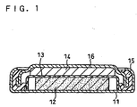
- a coin-type cell comprising was fabricated in the following procedure. A vertical sectional view of the obtained coin-type cell is shown in FIG. 1 .
- test electrode (positive electrode) 12 was disposed on the inner surface of a positive electrode case 11, and a separator 13 comprising a porous polyethylene sheet was disposed on the test electrode 12. Subsequently, an electrolyte was pouring into the positive electrode case 11.
- the electrolyte was prepared by dissolving 1 mol/L of lithium hexafluorophosphate (LiPF 6 ) in a mixed solvent of ethylene carbonate and diethyl carbonate in a weight ratio of 1:1.
- the fabricated coin-type cell was charged/discharged at a constant current of 0.133 mA and at a voltage in the range of 2.5 to 4.5 V at an ambient temperature of 20°C to determine discharge capacities at 1st, 50th, 100th and 300th cycles. Further, an average discharge voltage in respect to an oxidation-reduction potential of lithium (Li/Li + ) was determined. As the average discharge voltage used was the average of voltage values in the discharge at the 1st cycle. It is to be noted that there was almost no variation of the discharge voltage until the 300th cycle. The average of all voltage values in the case where a discharge curve has a staircase pattern through a two-steps discharging reaction was also determined. The results are shown in Table 1.
- a charge/discharge rate characteristic was evaluated.
- the fabricated coin-type cell was charged/discharged at a constant current of 0.133, 0.665, 1.33 or 2.66 mA and at a voltage in the range of 2.5 to 4.5 V at an ambient temperature of 20°C, and a discharge capacity at the 50th cycle at each of the above current values was determined. The results are shown in Table 2.
- the charging/discharging reaction mechanism of the organosulfur compound having the disulfide site used in COMPARATIVE EXAMPLE 1 is based on the dissociation and recombination reaction of the S-S bond. Since this reaction occurs with low frequency and the charging/discharging reaction causes a large change of the molecular structure, it is unlikely that the S-S bond is recombined. This can be considered a cause of the evaluation result that almost no discharge capacity was obtained at the 300th cycle even though a high discharge capacity was obtained in the initial cycles. It is accordingly found that, in the case of using a compound having a reaction mechanism based on the dissociation and recombination reaction of the S-S bond, an excellent cycle characteristic cannot be obtained.
- the electrochemical device including, as the electrode active material, the compound having the structure represented by the general formula (1a) or (2) has an excellent cycle characteristic.
- the electrochemical device including, as the electrode active material, the compound having the structure represented by the general formula (1a) or (2) has an excellent rate characteristic.
- a polymer compound having more than one structure represented by the chemical formula (3) was used as an electrode active material.
- a polymer compound having more than one structure represented by the chemical formula (3) was used as an electrode active material.
- a coin-type cell was fabricated in the same manner as in EXAMPLE 1. Subsequently, the fabricated coin-type cell was charged and discharged at a constant current of 0.133 mA and at a voltage in the range of 2.5 to 4.5 V at an ambient temperature of 20°C to determine discharge capacities at 1st, 50th, 100th and 300th cycles. The results are shown in Table 3.
- a lithium-containing composite nitride was prepared in such a manner that an alloy of lithium and cobalt in a molar ratio of 2.6:0.4 was put into a copper-made container and held there under a nitrogen atmosphere at 800°C for two hours so that the alloy was reacted with nitrogen. After the reaction, the resultant black ash colored nitride was pulverized into a powder to be used as a negative electrode active material.
- the obtained negative electrode active material powder was subjected to powder X-ray diffraction with CuK ⁇ radiation to observe the same hexagonal-based diffraction pattern as that of the lithium nitride (LiN 3 ). This confirmed formation of a single-phase solid solution in such a state as Co had been incorporated into the crystal structure of lithium nitride.
- the composition of the lithium-containing composite nitride thus synthesized was Li 2.6 Co 0.4 N.
- the Li 2.6 Co 0.4 N powder as thus obtained, a carbon powder and a polytetrafluoroethylene powder as a binder were mixed well in a weight ratio of 100:25:5 to give a negative electrode material mixture.
- This negative electrode material mixture was applied onto a copper sheet, followed by rolling, and the resultant electrode plate was punched out into a disk with a diameter of 13.5 mm to serve as a negative electrode.
- a powder of LiTi 5 O 12 was used as the lithium-containing composite titanium oxide.
- the LiTi 5 O 12 powder, a carbon powder and a polytetrafluoroethylene powder as a binder were mixed well in a weight ratio of 100:25:5 to give a negative electrode material mixture.
- This negative electrode material mixture was applied onto a copper sheet, followed by rolling, and the resultant electrode plate was punched out into a disk with a diameter of 13.5 mm to serve as a negative electrode.
- the coin-type cell was charged/discharged at a constant current of 0.133 mA and at a voltage in the range of 2.5 to 4.5 V at an ambient temperature of 20°C to determine discharge capacities at 1st, 50th, 100th and 300th cycles. The results are shown in Table 4.
- the electrochemical device where the compound having the structure represented by the general formula (1a) is used as one of the electrode active materials while the lithium-containing composite nitride or the lithium-containing composite titanium oxide is used as the other of the electrode active materials, also exhibits an excellent cycle characteristic.
- the compound having the structure represented by the general formula (2) was used as the active materials of both the positive electrode and the negative electrode.
- the compound represented by the chemical formula (7): was used as the positive electrode active material
- the compound represented by the chemical formula (4): was used as the negative electrode active material.
Description
- In recent years, with the development of mobile communication devices and mobile electronic equipments, the demand for power sources thereof have been greatly increased. Since batteries, especially lithium secondary batteries that can be repeatedly charged/discharged, have high electromotive force and high energy density so as to be repeatedly used, they have been in extensive use as power sources of mobile electronic equipments and the like.
- With the miniaturization as well as size-reduction of mobile electronic equipments, however, the demand is increasingly high for batteries with higher energy density, and the emergence of new electrode materials with higher energy density than conventional materials have been desired. In this background, active efforts are underway to develop new electrode materials with higher energy density that would directly lead to an increase in energy densities of batteries.
- In order to fabricate batteries with higher energy density and lighter weight, studies have recently been conducted on the use of organic compounds as electrode materials. Organic compounds are so light as to have a specific gravity of about 1 g/cm3, which is lighter than lithium cobaltate currently in use as a material for lithium secondary batteries. The use of organic compounds as electrode materials therefore allows fabrication of batteries lighter in weight and higher in capacity than conventional batteries.
- For example,
U.S. Patent No. 4,833,048 andJapanese Patent No. 2,715,778 - Further,
U.S. Patent Application No. 5,523,179 has proposed the use of elemental sulfur as an electrode material. - In either case, however, the problem arises that the materials have low cycle life characteristics although it is possible to achieve high capacity. This is because a recombination frequency is low in the dissociation and recombination of a disulfide bond during the oxidation-reduction reaction of a sulfur-based material. Low recombination frequency means that all reactive portions cannot react even if the material theoretically has high energy density. Therefore, it cannot actually be said that the compounds of the above related art examples are materials having high energy density.
- As thus described, in lightweight and high energy-density electrochemical devices using the organosulfur compound having the disulfide site as the electrode reaction site, as an electrode material, the organosulur compound structurally varies remarkably through an oxidation-reduction reaction, raising a problem of a low cycle characteristic. In the light of this, an object of the present invention is to improve a cycle characteristic of a lightweight electrochemical device having high energy density.
-
US2002/0027415 A1 discloses a dithiafulvene derivative represented by Formula (1):
- An electrochemical device of the present invention, comprises a positive electrode, a negative electrode and an electrolyte, wherein at least one of said positive electrode and said negative electrode includes a compound having a structure represented by the general formula (1a):

- A further electrochemical device of the present invention, comprises a positive electrode, a negative electrode and an electrolyte, wherein at least one of said positive electrode and said negative electrode includes a compound having a structure represented by the general formula (1b):

each of R1 to R4 is independently a methyl group, a linear or cyclic aliphatic group, a hydrogen atom, a hydroxyl group, a cyano group, an amino group, a nitro group or a nitroso group; each of R5 and R6 is independently a linear or cyclic aliphatic group or a hydrogen atom; said aliphatic group includes at least one selected from the group consisting of an oxygen atom, a nitrogen atom, a sulfur atom, a silicon atom, a phosphorus atom, a boron atom and a halogen atom. - Although it is preferable that each X in the general formula (1a) or (1b) is the same, it is contemplated that each X may be independently selected from sulfur, nitrogen or oxygen.
- A further electrochemical device of the present invention comprises a positive electrode, a negative electrode and an electrolyte, wherein at least one of said positive electrode and said negative electrode includes a compound represented by the general formula (2):

- It is preferable that the compound be a polymer compound having more than one structure represented by the general formula (1a), (1b) or (2).
- It is preferable that the electrolyte comprises a solvent, and an anion and a cation that diffuse in the solvent, and the compound be capable of forming a coordinate bond with the cation through an oxidation-reduction reaction.
- It is preferable that the cation be a lithium ion.
- It is preferable that the electrolyte comprises a solvent, and an anion and a cation that diffuse in the solvent, and the compound be capable of forming a coordinate bond with the anion through an oxidation-reduction reaction.
- It is preferable that the positive electrode includes the compound as a positive electrode active material, and the negative electrode include a carbon material as a negative electrode active material.
- It is preferable that the positive electrode includes the compound as a positive electrode active material, and the negative electrode include, as a negative electrode active material, at least one selected from the group consisting of a lithium metal, a lithium-containing composite nitride, a lithium-containing composite titanium oxide, a silicon-based alloy, and a silicon oxide.
-
-
FIG. 1 is a vertical sectional view of a coin-type cell fabricated in an example of the present invention - An electrochemical device of the present invention provides an electric energy by converting an electron transfer through an oxidation-reduction reaction into the electric energy, and comprises a positive electrode, a negative electrode and an electrolyte. At least one of the positive electrode and the negative electrode includes a compound having a structure represented by the general formula (1a), (1b) or (2).
General formula (1a) is:
General formula (1b) is:
each of R1 to R4 is independently a methyl group, a linear or cyclic aliphatic group, a hydrogen atom, a hydroxyl group, a cyano group, an amino group, a nitro group or a nitroso group; each of R5 and R6 is independently a linear or cyclic aliphatic group or a hydrogen atom; said aliphatic group includes at least ona selected from the group consisting of an oxygen atom, a nitrogen atom, a sulfur atom, silicon atom, a phosphorus atom, a boron atom and a halogen atom.
General formula (2) is:
- Hereinafter, the compound may be referred to as "active material compound". The active material compound as an electrode active material brings about an oxidation-reduction reaction within the battery to give and receive electrons.
- The active material compound can cause an oxidation-reduction reaction without any significant structural change therein. The mechanism is described below.
- The active material compound has a structural symmetry and a planar structure. Further, the active material compound has a carbon-carbon double bond at the center of the molecule thereof, and cyclic structures, including hetero atoms such as sulfur and oxygen. The hetero atoms have lone electron pairs. This causes formation of conjugation by π electrons on the molecule. In the π-electron conjugation portion, having spread over the molecule, electrons can be given and received. This giving and receiving of the electrons proceed as the oxidation-reduction reaction of the active material compound.
- For example, in a reductive reaction (discharging reaction), the active material compound is reduced and cations in an electrolyte are coordinated in the reduced molecule. In a subsequent oxidative reaction (charging reaction), the cations having been coordinated in the active material compound are eliminated. This reaction is usable as a battery reaction.
- Furthermore, when the active material compound is oxidized in the oxidative reaction (charging reaction), anions in the electrolyte are coordinated in the oxidized molecule. In a subsequent reductive reaction (discharging reaction), the anions having been coordinated in the active material compound are eliminated.
- In the above series of oxidative and reductive reactions, there is thought to be no significant structural change of the active material compound, such as dissociation and recombination of the bond. If the molecular structure of the compound significantly changes concomitantly with the oxidation-reduction reaction, another molecular structure change will be required during subsequent reaction, which requires considerable energy. Therefore, no significant structural change of the active material compound through the oxidation-reduction reaction indicates that the effective reaction can be conducted.
- As thus described, in the present invention, the compound, whose oxidation-reduction reaction occurs in the π-electron conjugation portion having spread over the molecule, is used as the electrode active material. In the above reaction mechanism, there occurs no significant change of the skeletal structure of the active material through the oxidation-redaction reaction. Accordingly, deterioration in structure of the active material, attributed to repetition of the oxidation-reduction reactions, is suppressed so that an excellent charge/discharge cycle characteristic can be obtained.
- Moreover, in the above reaction mechanism, the reaction is expected to proceed more rapidly than dissociation and recombination reaction cause by a conventional organosulfur compounds. When the reaction rate becomes faster, a rate characteristic excellent as a battery characteristic can be expected, and it is thus advantageous for rapid charge/discharge.
- As for the compound represented by the general formula (1a) or (1b), a compound represented by the chemical formula (3):


- Further, in the viewpoint of obtaining a faster electrode reaction rate, it is preferable that the active material compound be a compound represented by the general formula (2) :

- The reasons for the faster electrode reaction in the case of the general formula (2) are described below.
- In the oxidation-reduction reaction of the compound represented by the general formula (1a) or (1b), electrons are given and received on two five-membered rings and the reaction occurs in two steps. In the oxidation-reduction reaction of the compound represented by the general formula (2), although the reaction is similar to that in the case of the general general formula (1a) or (1b), the levels of energy to take electrons out of the two five-membered rings, get closer to each other in the presence of two benzene rings disposed between the two five-membered rings, and thereby a pseudo one step reaction proceeds. This is attributable that the structure obtained by one electron reaction is vary similar to the structure obtained by two electrons reaction.
- As for the compound represented by the general formula (2), a compound represented by the chemical formula (5):


- Each of R1 to R4 and R7 to R10 in the general formulae (1a), (1b) and (2) is preferably; a nitro group (NO2) so that a high voltage electrochemical device having an excellent charge/discharge cycle characteristic can be obtained; a cyano group (CN) so that a high voltage and high capacity electrochemical device can be obtained; or a methyl group (CH3) so that a high voltage and high capacity electrochemical device excellent in rate characteristic as well as cycle characteristic can be obtained.
- As for an aliphatic group used in each of R1 to R4 and R7 to R10 in the general formulae (1a), (1b) and (2), for example, an alkyl group, a cycloalkyl group, an alkoxy group, a hydroxyalkyl group, a thioalkyl group, an aldehyde group, a carboxylic acid group, an alkyl halide group can be cited. The carbon number of the aliphatic group is not particularly limited but is preferably from 1 to 6.
- Further, as for the active material compound, any compound including monomer compounds and polymer compound can be used so long as it has a structure represented by the general formula (1a), (1b) or (2). Those compounds can be used singly or in combination of two or more of them.
- In the present invention, the polymer compound is defined as a compound, with a molecular weight not less than 10,000, prepared by polymerization of monomer compounds. The polymer compound has a lower solubility in an electrolyte or the like than the monomer compound. In the case of using the polymer compound as the electrode active material, therefore, the dissolving of the active material in the electrolyte is inhibited to further enhance the stability of the cycle characteristic.
- As for the polymer compound preferably used is a compound obtained by polymerizing the compounds represented by the general formula (1a). Such a compound may be exemplified by one represented by the general formula (9):

- Moreover, as for the polymer compound, a compound having a polyacetylene chain, or a polymethylmethacrylate chain, as a main chain is preferred. It is further preferable that two or more of structures represented by the general formula (1a), (1b) or (2) be included in one molecule. It is preferable that the polyacetylene chain has a molecular weight of 10,000 to 200,000. Such a compound may be exemplified by one represented by the general formula (10):

- It is to be noted that the above compounds can be used singly or in combination of two or more of them.
- While the active material compound is preferably used as an electrode active material of a secondary battery, among electrochemical devices, it can also be used, for example, for electrodes of primary batteries, electrolytic capacitors, various sensors, electrochromic devices and the like. While these devices have been provided merely as examples, there are a large number of other devices for which the compound can be used.
- In secondary batteries, the active material compound can be used in both/either a positive electrode and/or a negative electrode. When this compound is used for one of the electrodes, a conventionally used material can be used for the other of the electrodes as an active material of a secondary battery without any particular limitation.
- In the case of using the confound having the structure represented by the general formula (1a), (1b) or (2) as the positive electrode active material, the following can be used as the negative electrode active material: a carbon material such as graphite or amorphous carbon, a lithium metal, a lithium-containing composite nitride, a lithium-containing composite titanium oxide, a composite material of tin and carbon, a composite material of tin and other metals, an alloy of silicon and other metals, a silicon oxide, or the like.
- Further, in the case of using the compound having the structure represented by the general formula (1a), (1b) or (2) as the negative electrode active material, the following can be used as the positive electrode active material: a metal oxide such as LiCoO2, LiNiO2 or LiMn2O4
- When the compound having the structure represented by the general formula (1a), (1b) or(2) is used as the electrode active material, a carbon material such as carbon black, graphite or acetylene black, π-conjugated polymer such as polyaniline, polypyrrole or polythiophene, or some other materials may be mixed into the electrode active material as a conductive material to decrease the electrode resistance. Further, as an ion-conductive material, a solid electrolyte comprising polyethylene oxide or the like, or a gel electrolyte comprising polymethyl methacrylate or the like, may be mixed into the electrode active material.
- Moreover, a binder may be used for the purpose of improving a bonding property of constituents of materials in the electrode. As for the binder used can be polyvinylidene fluoride, a copolymer of vinylidene fluoride and hexafluoropropylene, a copolymer of vinylidene fluoride and tetrafluoroethylene, polytetrafluoroethylene, a copolymer of styrene and butadiene, polypropylene, polyethylene, polyimide, polyacrylate or the like.
- As for a positive electrode current collector or a negative electrode current collector used can be metal foil, metal mesh, resin containing a conductive filler or the like, which is made of nickel, aluminum, gold, silver, copper, stainless steel, aluminum alloy or the like. By application of carbon or the like onto the current collector, the resistance value of the electrode may be reduced, the current collector may be provided with a catalytic effect, and the current collector and the active material may be chemically or physically bonded to one another.
- When a separator is interposed between the positive electrode and the negative electrode, the electrolyte is impregnated into a separator. It is preferable that the electrolyte comprises a solvent and a salt having dissolved in the solvent. Further, the electrolyte itself may be gelated so as to function as a separator. In this case, it is preferable that the electrolyte be impregnated into a matrix of a polymer including polyacrylonitrile, an acrylate unit or a methacrylate unit, a copolymer of ethylene and acrylonitrile, or the like. A cross-linked polymer is preferably used for the matrix.
- The preferable examples of the salt to be dissolved in the electrolyte may include halides of alkaline metals such as lithium, sodium and potassium, halides of an alkali earth metal such as magnesium, perchlorate, and salts of fluorine-containing compounds typified by trifluoromethanesulfonate. Specific examples thereof may include lithium fluoride, lithium chloride, lithium perchlorate, lithium trifluoromethanesulfonate, lithium tetrafluoroborate, lithium bis(trifluoromethylsulfonyl)imide, lithium thiocyanate, magnesium perchlorate, magnesium trifluoromethanesulfate and sodium tetrafluoroborate. Those can be used singly or in combination of two or more of them.
- The preferable examples of the solvent of the electrolyte may include organic solvents such as ethylene carbonate, propylene carbonate, dimethyl carbonate, diethyl carbonate, methyl ethyl carbonate, γ-butyrolactone, tetrahydrofuran, dioxolane, sulfolane and dimethylformamide.
- It should be noted that a solid electrolyte may be used except for the above electrolyte. As for the solid electrolyte cited can be Li2S-SiS2, Li2S-P2O5, Li2S-B2S5, Li2S-P2S5-GeS2, sodium/alumina (Al2O3), polyether with an amorphous or low-phase transition temperature (Tg), a copolymer of amorphous vinylidene fluoride-hexafluoropropylene, blends of different polymer or polyethylene oxide.
- Next, the present invention is described in detail based on examples. In each example, a coin-type cell was fabricated to evaluate an electrode active material. In the following, a method for preparing a test electrode, a method for fabricating a coin-type cell and an evaluation of battery characteristics are sequentially described.
- The following operation was performed under an argon-gas atmosphere in a dry box equipped a gas purifier.
- As an electrode active material used was a compound represented by the chemical formula (3):

- 30 mg of the compound represented by the chemical formula (3) and 30 mg of acetylene black as a conductive material were mixed to be uniform, which was then added with 1 ml of N-methyl-2-pyrrolidone as a solvent. The obtained mixture was added with 5 mg of polyvinylidene fluoride as a binder for the purpose of binding the active material to the conductive material, which was mixed to be uniform so as to give a black slurry. This slurry was applied on a current collector made of aluminum foil and then subjected to vacuum drying at room temperature for one hour. After the drying, the obtained matter was punched out into a disc with a diameter of 13.5 mm to serve as a test electrode.
- Using the test electrode prepared in the aforementioned method as a positive electrode and lithium metal of 13.5mm disk (thickness: 300 µm) as a negative electrode, a coin-type cell comprising was fabricated in the following procedure. A vertical sectional view of the obtained coin-type cell is shown in
FIG. 1 . - First, the test electrode (positive electrode) 12 was disposed on the inner surface of a
positive electrode case 11, and aseparator 13 comprising a porous polyethylene sheet was disposed on thetest electrode 12. Subsequently, an electrolyte was pouring into thepositive electrode case 11. The electrolyte was prepared by dissolving 1 mol/L of lithium hexafluorophosphate (LiPF6) in a mixed solvent of ethylene carbonate and diethyl carbonate in a weight ratio of 1:1. - Further prepared was a sealing
plate 16, to the inner wall of which metallic lithium (negative electrode) 14 was attached by pressure and in the periphery of which asealing ring 15 was placed. Themetallic lithium 14 was then made opposed to thetest electrode 12 and thecase 11 was sealed with the sealingplate 16. The open end of thecase 11 was crimped on the sealingring 15 with a pressing machine to obtain a coin-type cell for evaluation. - The fabricated coin-type cell was charged/discharged at a constant current of 0.133 mA and at a voltage in the range of 2.5 to 4.5 V at an ambient temperature of 20°C to determine discharge capacities at 1st, 50th, 100th and 300th cycles. Further, an average discharge voltage in respect to an oxidation-reduction potential of lithium (Li/Li+) was determined. As the average discharge voltage used was the average of voltage values in the discharge at the 1st cycle. It is to be noted that there was almost no variation of the discharge voltage until the 300th cycle. The average of all voltage values in the case where a discharge curve has a staircase pattern through a two-steps discharging reaction was also determined. The results are shown in Table 1.
Table 1 Discharge Capacity(mAh/g) Average discharge voltage(E/V vs. Li/Li+) 1st 50th 100th 300th Ex.1 230 230 230 230 3.6 Ex.2 140 138 138 137 3.7 Ex.3 98 98 96 96 3.7 Ex.4 121 120 120 120 3.75 Ex.5 127 125 125 125 3.75 Com.Ex.1 280 20 20 15 2.8 - Moreover, a charge/discharge rate characteristic was evaluated. Herein, the fabricated coin-type cell was charged/discharged at a constant current of 0.133, 0.665, 1.33 or 2.66 mA and at a voltage in the range of 2.5 to 4.5 V at an ambient temperature of 20°C, and a discharge capacity at the 50th cycle at each of the above current values was determined. The results are shown in Table 2.
Table 2 Discharge capacity at 50th cycle (mAh/g) 0.133mA 0.665mA 1.33mA 2.66mA Ex.1 230 230 225 221 Ex.2 140 140 138 135 Ex.3 98 96 91 90 Ex.4 121 120 119 112 Ex.5 127 126 126 126 Com.Ex.1 20 12 12 11 - Except that an organosulfur compound of 2,5-dimercapto-1,3,4-thiadiazole (produced by Aldrich) was used as the active material of the test electrode, a coin-type cell was fabricated and then evaluated in the same manner as in EXAMPLE 1. The results are shown in Tables 1 and 2.
- Except that a compound represented by the chemical formula (5):

- Except that a compound represented by the chemical formula (8):

- Except that a compound represented by the chemical formula (6):

- Except that a compound represented by the chemical formula (7):

- According to the results shown in Table 1, in COMPARATIVE EXAMPLE 1 where the organosulfur compound having the disulfide site as the electrode reaction site, was used as the electrode active material, although the capacity of 280 mAh/g was obtained in the initial discharge, the capacity decreased by 20 mAh/g until the 50th cycle, and the capacity of only about 15 mAh/g was obtained at the 300th cycle.
- On the other hand, in each of EXAMPLES 1 to 5 where the compound having the structure represented by the general formula (1a) or (2) was used as the electrode active material, a high average discharge voltage of about 3.5 V was obtained and almost no decrease in discharge capacity was observed even at the 300th cycle.
- The charging/discharging reaction mechanism of the organosulfur compound having the disulfide site used in COMPARATIVE EXAMPLE 1 is based on the dissociation and recombination reaction of the S-S bond. Since this reaction occurs with low frequency and the charging/discharging reaction causes a large change of the molecular structure, it is unlikely that the S-S bond is recombined. This can be considered a cause of the evaluation result that almost no discharge capacity was obtained at the 300th cycle even though a high discharge capacity was obtained in the initial cycles. It is accordingly found that, in the case of using a compound having a reaction mechanism based on the dissociation and recombination reaction of the S-S bond, an excellent cycle characteristic cannot be obtained.
- On the other hand, the compound having the structure represented by the general formula (1a) or (2), which was used in EXAMPLES 1 to 5 of the present invention, there was observed almost no decrease in discharge capacity even at the 300th cycle. This is presumably because, in the charging/discharging reaction of this compound, anions and cations are just coordinated on molecules and hence the molecular structure does not significantly change, thereby causing no deterioration of the compound itself due to repetition of charging/discharging.
- It is found from the above results that the electrochemical device including, as the electrode active material, the compound having the structure represented by the general formula (1a) or (2) has an excellent cycle characteristic.
- Further, as apparent from the results of Table 2, the electrochemical device including, as the electrode active material, the compound having the structure represented by the general formula (1a) or (2) has an excellent rate characteristic.
- Next, an example is described where a polymer compound having more than one structure represented by the chemical formula (3) was used as an electrode active material. Herein, as a compound having a polyethylene chain as a main chain and more than one structure represented by the chemical formula (3), there was used a compound represented by the general formula (9):

- Except that 40 mg of the compound represented by the general formula (9) was used in place of 30 mg the compound represented by the chemical formula (3), a coin-type cell was fabricated in the same manner as in EXAMPLE 1. Subsequently, the fabricated coin-type cell was charged and discharged at a constant current of 0.133 mA and at a voltage in the range of 2.5 to 4.5 V at an ambient temperature of 20°C to determine discharge capacities at 1st, 50th, 100th and 300th cycles. The results are shown in Table 3.
Table 3 Discharge Capacity(mAh/g) Average discharge voltage(E/V vs. Li/Li+) 1st 50th 100th 300th Ex.6 135 132 130 130 3.7 Ex.7 90 88 86 84 3.6 - Next, an example is described where a polymer compound having more than one structure represented by the chemical formula (3) was used as an electrode active material. Herein, as a compound having a polyacetylene chain as a main chain and more than one structure represented by the chemical formula (3), there was used a compound represented by the general formula (10):

- Except that 40 mg of the compound represented by the general formula (10) was used in place of 30 mg of the compound represented by the formula (3), a coin-type cell was fabricated in the same manner as in EXAMPLE 1. Subsequently, the fabricated coin-type cell was charged and discharged at a constant current of 0.133 mA and at a voltage in the range of 2.5 to 4.5 V at an ambient temperature of 20°C to determine discharge capacities at 1st, 50th, 100th and 300th cycles. The results are shown in Table 3.
- It is found from the results of Table 3 that the electrochemical device, using the polymer compound having more than one structure represented by the general formula (1a) as the electrode active material, also exhibits an excellent cycle characteristic.
- Next, an example is described where a lithium-containing composite nitride was used as the negative electrode. Except that a below-described negative electrode was used, a coin-type cell was fabricated in the same manner as in EXAMPLE 1.
- A lithium-containing composite nitride was prepared in such a manner that an alloy of lithium and cobalt in a molar ratio of 2.6:0.4 was put into a copper-made container and held there under a nitrogen atmosphere at 800°C for two hours so that the alloy was reacted with nitrogen. After the reaction, the resultant black ash colored nitride was pulverized into a powder to be used as a negative electrode active material.
- The obtained negative electrode active material powder was subjected to powder X-ray diffraction with CuKα radiation to observe the same hexagonal-based diffraction pattern as that of the lithium nitride (LiN3). This confirmed formation of a single-phase solid solution in such a state as Co had been incorporated into the crystal structure of lithium nitride. The composition of the lithium-containing composite nitride thus synthesized was Li2.6Co0.4N.
- The Li2.6Co0.4N powder as thus obtained, a carbon powder and a polytetrafluoroethylene powder as a binder were mixed well in a weight ratio of 100:25:5 to give a negative electrode material mixture. This negative electrode material mixture was applied onto a copper sheet, followed by rolling, and the resultant electrode plate was punched out into a disk with a diameter of 13.5 mm to serve as a negative electrode.
- For the positive electrode used was the same test electrode as prepared in EXAMPLE 1. The coin-type cell was charged/discharged at a constant current of 0.133 mA and at a voltage in the range of 2.5 to 4.5 V at an ambient temperature of 20°C to determine discharge capacities at 1st, 50th, 100th and 300th cycles. The results are shown in Table 4.
Table 4 Discharge Capacity(mAh/g) Average discharge voltage(E/V vs. Li/Li+) 1st 50th 100th 300th Ex.8 230 230 230 228 3.05 Ex.9 230 228 224 218 2.8 - Next, an example is described where a lithium-containing composite titanium oxide was used as the negative electrode. Except that a below-described negative electrode was used, a coin-type cell was fabricated in the same manner as in EXAMPLE 1.
- A powder of LiTi5O12 was used as the lithium-containing composite titanium oxide. The LiTi5O12 powder, a carbon powder and a polytetrafluoroethylene powder as a binder were mixed well in a weight ratio of 100:25:5 to give a negative electrode material mixture. This negative electrode material mixture was applied onto a copper sheet, followed by rolling, and the resultant electrode plate was punched out into a disk with a diameter of 13.5 mm to serve as a negative electrode.
- For the positive electrode used was the same test electrode as prepared in EXAMPLE 1. The coin-type cell was charged/discharged at a constant current of 0.133 mA and at a voltage in the range of 2.5 to 4.5 V at an ambient temperature of 20°C to determine discharge capacities at 1st, 50th, 100th and 300th cycles. The results are shown in Table 4.
- It is found from the results of Table 4 that the electrochemical device, where the compound having the structure represented by the general formula (1a) is used as one of the electrode active materials while the lithium-containing composite nitride or the lithium-containing composite titanium oxide is used as the other of the electrode active materials, also exhibits an excellent cycle characteristic.
- Next, an example is described where the compound having the structure represented by the general formula (2) was used as the active materials of both the positive electrode and the negative electrode. Herein, the compound represented by the chemical formula (7):


- Except that the above compounds were respectively used as the positive electrode active material and the negative electrode active material, the same coin-type cell was fabricated in the same manner as in EXAMPLE 1. Namely, in place of the compound represented by the chemical formula (3) and metallic lithium, the compound represented by the chemical formula (7) and the compound represented by the chemical formula (4) were respectively used to prepare two test electrodes, and the former test electrode was used as a positive electrode while the latter test electrode was used as a negative electrode, to fabricate a coin-type cell. The resultant coin-type cell was then charged/discharged at a constant current of 0.133 mA and at a voltage in the range of 0.3 to 0.6 V at an ambient temperature of 20°C to determine discharge capacities at 1st, 50th, 100th and 300th cycles. The results are shown in Table 5.
Table 5 Discharge Capacity(mAh/g) Average discharge voltage(E/V vs. Li/Li+) 1st 50th 100th 300th Ex.10 180 178 175 170 0.5 - It is found from the results of Table 5 that an cycle characteristic can be obtained even when the compound represented by the general formula (Z) was used for both electrodes.
- Although the present invention has been described in terms of the presently preferred embodiments, it is to be understood that such disclosure is not to be interpreted as limiting.
Claims (18)
- An electrode active material for an electrochemical device, comprising a compound having a structure represented by the general formula (1a):

- An electrode active material for an electrochemical device, comprising a compound having a structure represented by the general formula (1b):

- An electrode active material for an electrochemical device comprising a compound having a structure represented by the general formula (2):

- An electrode active material in accordance with any one of claims 1 to 3, wherein said compound is a polymer compound having more than one structure represented by the general formula (1a), (1b) or (2).
- An electrode active material in accordance with claim 4 wherein said compound is represented by the general formula (9):

- An electrode active material in accordance with claim 4 wherein the polymer compound has a polyacetylene claim or a polymethacrylate claim as a main chain.
- An electrode active material in accordance with claim 6 wherein said compound is represented by the general formula (10):

- An electrode active material in accordance with any of claims 1 to 4, wherein the number of carbon atoms in the aliphatic group is in the range of 1 to 6.
- An electrode active material in accordance with claim 3 wherein each of R1 to R4, R8 and R10 is a hydrogen atom; and each of R7 and R9 is a methyl group.
- An electrochemical device, comprising a positive electrode, a negative electrode and an electrolyte, wherein at least one of said positive electrode and said negative electrode includes an electrode active material comprising a compound having a structure represented by general formula (1a), (1b) or (2) in accordance with any one of claims 1to 9.
- An electrochemical device in accordance with claim 10, wherein said electrolyte comprises a solvent, and an anion and a cation that diffuse in said solvent, and said compound is capable of forming a coordinate bond with said cation through an oxidation-reduction reaction.
- An electrochemical device in accordance with claim 11, wherein said cation is a lithium ion.
- An electrochemical device in accordance with any one of claims 10 to 12, wherein said positive electrode includes said compound as a positive electrode active material, and said negative electrode includes a carbon material as a negative electrode active material.
- An electrochemical device in accordance with any one of claims 10 to 12, wherein said positive electrode includes said compound as a positive electrode active material, and said negative electrode includes, as a negative electrode active material, at least one selected from the group consisting of a lithium metal, a lithium-containing composite nitride and a lithium-containing composite titanium oxide.
- An electrochemical device in accordance with any of claims 10 to 12 wherein said negative electrode includes said compound as a negative electrode active material, and said positive electrode includes a metal oxide material as a positive electrode active material.
- An electrochemical device in accordance with any of claims 10 to 14 wherein when said compound is used as an electrode active material, a conductive material is mixed into the electrode active material.
- An electrochemical device in accordance with any of claims 10 to 12 wherein when said positive electrode includes said compound as a positive electrode active material, one of the following is used as the negative electrode material of said negative electrode: a carbon material, a lithium metal, a lithium-containing composite nitride, a lithium-containing composite titanium oxide, a composite material of tin and carbon, and a composite material of tin and another metal.
- An electrochemical device in accordance with any one of claims 10 to 17, wherein said electrochemical device comprises one of a secondary battery, a primary battery, an electrolytic capacitor, a sensor and an electrochromic device.
Applications Claiming Priority (2)
| Application Number | Priority Date | Filing Date | Title |
|---|---|---|---|
| JP2003116843 | 2003-04-22 | ||
| JP2003116843 | 2003-04-22 |
Publications (2)
| Publication Number | Publication Date |
|---|---|
| EP1478040A1 EP1478040A1 (en) | 2004-11-17 |
| EP1478040B1 true EP1478040B1 (en) | 2008-04-23 |
Family
ID=33028291
Family Applications (1)
| Application Number | Title | Priority Date | Filing Date |
|---|---|---|---|
| EP04252356A Expired - Fee Related EP1478040B1 (en) | 2003-04-22 | 2004-04-21 | Electrochemical device and electrode active material for electrochemical device |
Country Status (4)
| Country | Link |
|---|---|
| US (1) | US8034484B2 (en) |
| EP (1) | EP1478040B1 (en) |
| CN (1) | CN1264237C (en) |
| DE (1) | DE602004013216T2 (en) |
Families Citing this family (21)
| Publication number | Priority date | Publication date | Assignee | Title |
|---|---|---|---|---|
| CN101185185B (en) * | 2005-05-31 | 2010-04-07 | 松下电器产业株式会社 | Secondary battery, power supply system using same and usage of power supply system |
| US10050274B2 (en) * | 2006-05-12 | 2018-08-14 | Panasonic Intellectual Property Management Co., Ltd. | Power storage device |
| WO2009157206A1 (en) * | 2008-06-25 | 2009-12-30 | パナソニック株式会社 | Electricity storage material and electricity storage device |
| WO2010013492A1 (en) * | 2008-07-31 | 2010-02-04 | パナソニック株式会社 | Polymer, semiconductor film, electrode, electrode active material, electrochemical element and electricity storage device |
| CN101809789B (en) * | 2008-07-31 | 2013-09-18 | 松下电器产业株式会社 | Accumulator material and accumulator device |
| CN102484253B (en) | 2010-02-15 | 2014-10-15 | 松下电器产业株式会社 | Electrode active material for electrical storage device, electrical storage device, electronic device, and transport device |
| WO2013111713A1 (en) | 2012-01-23 | 2013-08-01 | 日産化学工業株式会社 | Carbazole polymer |
| CA2888463C (en) | 2012-10-16 | 2021-01-26 | Ambri Inc. | Electrochemical energy storage devices and housings |
| US11211641B2 (en) | 2012-10-18 | 2021-12-28 | Ambri Inc. | Electrochemical energy storage devices |
| US11387497B2 (en) | 2012-10-18 | 2022-07-12 | Ambri Inc. | Electrochemical energy storage devices |
| US11721841B2 (en) | 2012-10-18 | 2023-08-08 | Ambri Inc. | Electrochemical energy storage devices |
| US10541451B2 (en) | 2012-10-18 | 2020-01-21 | Ambri Inc. | Electrochemical energy storage devices |
| US10270139B1 (en) | 2013-03-14 | 2019-04-23 | Ambri Inc. | Systems and methods for recycling electrochemical energy storage devices |
| US9502737B2 (en) | 2013-05-23 | 2016-11-22 | Ambri Inc. | Voltage-enhanced energy storage devices |
| JP6685898B2 (en) | 2013-10-16 | 2020-04-22 | アンブリ・インコーポレイテッド | Seals for high temperature reactive material devices |
| US10181800B1 (en) | 2015-03-02 | 2019-01-15 | Ambri Inc. | Power conversion systems for energy storage devices |
| WO2016141354A2 (en) | 2015-03-05 | 2016-09-09 | Ambri Inc. | Ceramic materials and seals for high temperature reactive material devices |
| JP6361599B2 (en) * | 2015-07-07 | 2018-07-25 | 株式会社豊田中央研究所 | Power storage device |
| US11929466B2 (en) | 2016-09-07 | 2024-03-12 | Ambri Inc. | Electrochemical energy storage devices |
| JP7201613B2 (en) | 2017-04-07 | 2023-01-10 | アンブリ・インコーポレイテッド | Molten salt battery with solid metal cathode |
| US11431040B2 (en) * | 2018-08-31 | 2022-08-30 | Purdue Research Foundation | Arrangement for lithium-ion battery thermal events prediction, prevention, and control |
Family Cites Families (9)
| Publication number | Priority date | Publication date | Assignee | Title |
|---|---|---|---|---|
| US2715778A (en) | 1954-04-26 | 1955-08-23 | Kenneth A Murdock | Angle calculator |
| US4312992A (en) | 1976-12-03 | 1982-01-26 | International Business Machines Corporation | Substituted heterofulvalenes |
| US4833048A (en) | 1988-03-31 | 1989-05-23 | The United States Of America As Represented By The United States Department Of Energy | Metal-sulfur type cell having improved positive electrode |
| JP2715778B2 (en) | 1991-01-29 | 1998-02-18 | 松下電器産業株式会社 | Reversible electrode material |
| US5523179A (en) | 1994-11-23 | 1996-06-04 | Polyplus Battery Company | Rechargeable positive electrode |
| US5833048A (en) | 1995-02-07 | 1998-11-10 | Eaton Corporation | Rocker switch especially for vehicles |
| US6110619A (en) * | 1997-12-19 | 2000-08-29 | Moltech Corporation | Electrochemical cells with cationic polymers and electroactive sulfur compounds |
| US6617053B2 (en) * | 2000-08-04 | 2003-09-09 | Chisso Corporation | Organic electroluminescent device containing dithiafulvene derivative |
| US7282298B2 (en) | 2002-08-29 | 2007-10-16 | Matsushita Electric Industrial Co., Ltd. | Electrochemical device |
-
2004
- 2004-04-20 US US10/827,424 patent/US8034484B2/en not_active Expired - Fee Related
- 2004-04-21 EP EP04252356A patent/EP1478040B1/en not_active Expired - Fee Related
- 2004-04-21 DE DE602004013216T patent/DE602004013216T2/en not_active Expired - Lifetime
- 2004-04-22 CN CNB2004100353141A patent/CN1264237C/en not_active Expired - Lifetime
Also Published As
| Publication number | Publication date |
|---|---|
| US8034484B2 (en) | 2011-10-11 |
| CN1264237C (en) | 2006-07-12 |
| CN1540786A (en) | 2004-10-27 |
| DE602004013216D1 (en) | 2008-06-05 |
| DE602004013216T2 (en) | 2009-06-18 |
| EP1478040A1 (en) | 2004-11-17 |
| US20040214082A1 (en) | 2004-10-28 |
Similar Documents
| Publication | Publication Date | Title |
|---|---|---|
| EP1478040B1 (en) | Electrochemical device and electrode active material for electrochemical device | |
| EP1381100B1 (en) | Electricity storage device | |
| US8242213B2 (en) | Method for manufacturing polyradical compound and battery | |
| JP4467926B2 (en) | Electrochemical element | |
| EP1722430B1 (en) | Secondary battery using a radical compound as active electrode material | |
| EP2025689B1 (en) | Process for production of polyradical compound and battery cell | |
| EP1881544A1 (en) | Positive electrode material for lithium secondary cell | |
| EP1416553B1 (en) | Electrochemical device with unsaturated Organic Electrode Material | |
| JP4468058B2 (en) | Secondary battery and electrode active material for secondary battery | |
| JP5036214B2 (en) | Charge / discharge control method for power storage device | |
| US6337155B1 (en) | Battery and method of manufacture thereof | |
| JP2006324179A (en) | Electrode and electrochemical element using it | |
| JP5818689B2 (en) | Lithium ion secondary battery | |
| JP2008159275A (en) | Electrode active material and power storage device using the same | |
| JP2013134947A (en) | Electrode active material and secondary battery containing the same | |
| KR100606170B1 (en) | Secondary battery | |
| JP2008078040A (en) | Secondary battery | |
| JP4314508B2 (en) | Radical battery | |
| JP4737365B2 (en) | Electrode active material, battery and polymer | |
| JP5536519B2 (en) | Electrode active material and secondary battery | |
| JP3444463B2 (en) | Electrode containing organic disulfide compound and method for producing the same | |
| JP4752217B2 (en) | Active materials, batteries and polymers | |
| JP2005228640A (en) | Secondary battery | |
| KR100454503B1 (en) | Cathode material including poly(dithiodianiline) derivatives, lithium rechargeable battery obtained therefrom and manufacturing methods thereof | |
| JP2010165491A (en) | Electrode active material and secondary battery using it |
Legal Events
| Date | Code | Title | Description |
|---|---|---|---|
| PUAI | Public reference made under article 153(3) epc to a published international application that has entered the european phase |
Free format text: ORIGINAL CODE: 0009012 |
|
| AK | Designated contracting states |
Kind code of ref document: A1 Designated state(s): AT BE BG CH CY CZ DE DK EE ES FI FR GB GR HU IE IT LI LU MC NL PL PT RO SE SI SK TR |
|
| AX | Request for extension of the european patent |
Extension state: AL HR LT LV MK |
|
| 17P | Request for examination filed |
Effective date: 20041209 |
|
| 17Q | First examination report despatched |
Effective date: 20050620 |
|
| AKX | Designation fees paid |
Designated state(s): DE FR GB |
|
| GRAP | Despatch of communication of intention to grant a patent |
Free format text: ORIGINAL CODE: EPIDOSNIGR1 |
|
| GRAS | Grant fee paid |
Free format text: ORIGINAL CODE: EPIDOSNIGR3 |
|
| GRAA | (expected) grant |
Free format text: ORIGINAL CODE: 0009210 |
|
| AK | Designated contracting states |
Kind code of ref document: B1 Designated state(s): DE FR GB |
|
| REG | Reference to a national code |
Ref country code: GB Ref legal event code: FG4D |
|
| REF | Corresponds to: |
Ref document number: 602004013216 Country of ref document: DE Date of ref document: 20080605 Kind code of ref document: P |
|
| RAP2 | Party data changed (patent owner data changed or rights of a patent transferred) |
Owner name: PANASONIC CORPORATION |
|
| ET | Fr: translation filed | ||
| PLBE | No opposition filed within time limit |
Free format text: ORIGINAL CODE: 0009261 |
|
| STAA | Information on the status of an ep patent application or granted ep patent |
Free format text: STATUS: NO OPPOSITION FILED WITHIN TIME LIMIT |
|
| 26N | No opposition filed |
Effective date: 20090126 |
|
| PGFP | Annual fee paid to national office [announced via postgrant information from national office to epo] |
Ref country code: GB Payment date: 20130417 Year of fee payment: 10 |
|
| PGFP | Annual fee paid to national office [announced via postgrant information from national office to epo] |
Ref country code: FR Payment date: 20130625 Year of fee payment: 10 |
|
| GBPC | Gb: european patent ceased through non-payment of renewal fee |
Effective date: 20140421 |
|
| REG | Reference to a national code |
Ref country code: FR Ref legal event code: ST Effective date: 20141231 |
|
| PG25 | Lapsed in a contracting state [announced via postgrant information from national office to epo] |
Ref country code: GB Free format text: LAPSE BECAUSE OF NON-PAYMENT OF DUE FEES Effective date: 20140421 |
|
| PG25 | Lapsed in a contracting state [announced via postgrant information from national office to epo] |
Ref country code: FR Free format text: LAPSE BECAUSE OF NON-PAYMENT OF DUE FEES Effective date: 20140430 |
|
| PGFP | Annual fee paid to national office [announced via postgrant information from national office to epo] |
Ref country code: DE Payment date: 20220223 Year of fee payment: 19 |
|
| REG | Reference to a national code |
Ref country code: DE Ref legal event code: R119 Ref document number: 602004013216 Country of ref document: DE |
|
| PG25 | Lapsed in a contracting state [announced via postgrant information from national office to epo] |
Ref country code: DE Free format text: LAPSE BECAUSE OF NON-PAYMENT OF DUE FEES Effective date: 20231103 |