EP1477734A2 - Heizeinrichtung - Google Patents
Heizeinrichtung Download PDFInfo
- Publication number
- EP1477734A2 EP1477734A2 EP04450070A EP04450070A EP1477734A2 EP 1477734 A2 EP1477734 A2 EP 1477734A2 EP 04450070 A EP04450070 A EP 04450070A EP 04450070 A EP04450070 A EP 04450070A EP 1477734 A2 EP1477734 A2 EP 1477734A2
- Authority
- EP
- European Patent Office
- Prior art keywords
- burnout
- train
- secondary air
- heating device
- chamber
- Prior art date
- Legal status (The legal status is an assumption and is not a legal conclusion. Google has not performed a legal analysis and makes no representation as to the accuracy of the status listed.)
- Granted
Links
Images



Classifications
-
- F—MECHANICAL ENGINEERING; LIGHTING; HEATING; WEAPONS; BLASTING
- F23—COMBUSTION APPARATUS; COMBUSTION PROCESSES
- F23B—METHODS OR APPARATUS FOR COMBUSTION USING ONLY SOLID FUEL
- F23B5/00—Combustion apparatus with arrangements for burning uncombusted material from primary combustion
- F23B5/04—Combustion apparatus with arrangements for burning uncombusted material from primary combustion in separate combustion chamber; on separate grate
-
- F—MECHANICAL ENGINEERING; LIGHTING; HEATING; WEAPONS; BLASTING
- F23—COMBUSTION APPARATUS; COMBUSTION PROCESSES
- F23B—METHODS OR APPARATUS FOR COMBUSTION USING ONLY SOLID FUEL
- F23B10/00—Combustion apparatus characterised by the combination of two or more combustion chambers
- F23B10/02—Combustion apparatus characterised by the combination of two or more combustion chambers including separate secondary combustion chambers
-
- F—MECHANICAL ENGINEERING; LIGHTING; HEATING; WEAPONS; BLASTING
- F23—COMBUSTION APPARATUS; COMBUSTION PROCESSES
- F23B—METHODS OR APPARATUS FOR COMBUSTION USING ONLY SOLID FUEL
- F23B80/00—Combustion apparatus characterised by means creating a distinct flow path for flue gases or for non-combusted gases given off by the fuel
-
- F—MECHANICAL ENGINEERING; LIGHTING; HEATING; WEAPONS; BLASTING
- F23—COMBUSTION APPARATUS; COMBUSTION PROCESSES
- F23G—CREMATION FURNACES; CONSUMING WASTE PRODUCTS BY COMBUSTION
- F23G5/00—Incineration of waste; Incinerator constructions; Details, accessories or control therefor
- F23G5/08—Incineration of waste; Incinerator constructions; Details, accessories or control therefor having supplementary heating
- F23G5/14—Incineration of waste; Incinerator constructions; Details, accessories or control therefor having supplementary heating including secondary combustion
- F23G5/16—Incineration of waste; Incinerator constructions; Details, accessories or control therefor having supplementary heating including secondary combustion in a separate combustion chamber
-
- F—MECHANICAL ENGINEERING; LIGHTING; HEATING; WEAPONS; BLASTING
- F23—COMBUSTION APPARATUS; COMBUSTION PROCESSES
- F23G—CREMATION FURNACES; CONSUMING WASTE PRODUCTS BY COMBUSTION
- F23G5/00—Incineration of waste; Incinerator constructions; Details, accessories or control therefor
- F23G5/24—Incineration of waste; Incinerator constructions; Details, accessories or control therefor having a vertical, substantially cylindrical, combustion chamber
- F23G5/26—Incineration of waste; Incinerator constructions; Details, accessories or control therefor having a vertical, substantially cylindrical, combustion chamber having rotating bottom
-
- F—MECHANICAL ENGINEERING; LIGHTING; HEATING; WEAPONS; BLASTING
- F23—COMBUSTION APPARATUS; COMBUSTION PROCESSES
- F23G—CREMATION FURNACES; CONSUMING WASTE PRODUCTS BY COMBUSTION
- F23G5/00—Incineration of waste; Incinerator constructions; Details, accessories or control therefor
- F23G5/32—Incineration of waste; Incinerator constructions; Details, accessories or control therefor the waste being subjected to a whirling movement, e.g. cyclonic incinerators
-
- F—MECHANICAL ENGINEERING; LIGHTING; HEATING; WEAPONS; BLASTING
- F23—COMBUSTION APPARATUS; COMBUSTION PROCESSES
- F23J—REMOVAL OR TREATMENT OF COMBUSTION PRODUCTS OR COMBUSTION RESIDUES; FLUES
- F23J1/00—Removing ash, clinker, or slag from combustion chambers
- F23J1/06—Mechanically-operated devices, e.g. clinker pushers
-
- F—MECHANICAL ENGINEERING; LIGHTING; HEATING; WEAPONS; BLASTING
- F23—COMBUSTION APPARATUS; COMBUSTION PROCESSES
- F23L—SUPPLYING AIR OR NON-COMBUSTIBLE LIQUIDS OR GASES TO COMBUSTION APPARATUS IN GENERAL ; VALVES OR DAMPERS SPECIALLY ADAPTED FOR CONTROLLING AIR SUPPLY OR DRAUGHT IN COMBUSTION APPARATUS; INDUCING DRAUGHT IN COMBUSTION APPARATUS; TOPS FOR CHIMNEYS OR VENTILATING SHAFTS; TERMINALS FOR FLUES
- F23L1/00—Passages or apertures for delivering primary air for combustion
- F23L1/02—Passages or apertures for delivering primary air for combustion by discharging the air below the fire
-
- F—MECHANICAL ENGINEERING; LIGHTING; HEATING; WEAPONS; BLASTING
- F23—COMBUSTION APPARATUS; COMBUSTION PROCESSES
- F23L—SUPPLYING AIR OR NON-COMBUSTIBLE LIQUIDS OR GASES TO COMBUSTION APPARATUS IN GENERAL ; VALVES OR DAMPERS SPECIALLY ADAPTED FOR CONTROLLING AIR SUPPLY OR DRAUGHT IN COMBUSTION APPARATUS; INDUCING DRAUGHT IN COMBUSTION APPARATUS; TOPS FOR CHIMNEYS OR VENTILATING SHAFTS; TERMINALS FOR FLUES
- F23L9/00—Passages or apertures for delivering secondary air for completing combustion of fuel
- F23L9/04—Passages or apertures for delivering secondary air for completing combustion of fuel by discharging the air beyond the fire, i.e. nearer the smoke outlet
-
- F—MECHANICAL ENGINEERING; LIGHTING; HEATING; WEAPONS; BLASTING
- F23—COMBUSTION APPARATUS; COMBUSTION PROCESSES
- F23M—CASINGS, LININGS, WALLS OR DOORS SPECIALLY ADAPTED FOR COMBUSTION CHAMBERS, e.g. FIREBRIDGES; DEVICES FOR DEFLECTING AIR, FLAMES OR COMBUSTION PRODUCTS IN COMBUSTION CHAMBERS; SAFETY ARRANGEMENTS SPECIALLY ADAPTED FOR COMBUSTION APPARATUS; DETAILS OF COMBUSTION CHAMBERS, NOT OTHERWISE PROVIDED FOR
- F23M5/00—Casings; Linings; Walls
- F23M5/08—Cooling thereof; Tube walls
-
- F—MECHANICAL ENGINEERING; LIGHTING; HEATING; WEAPONS; BLASTING
- F23—COMBUSTION APPARATUS; COMBUSTION PROCESSES
- F23G—CREMATION FURNACES; CONSUMING WASTE PRODUCTS BY COMBUSTION
- F23G2205/00—Waste feed arrangements
- F23G2205/12—Waste feed arrangements using conveyors
- F23G2205/121—Screw conveyor
Definitions
- the invention relates to a heating device according to the preamble of claim 1.
- the burnout space is usually a large number on trains that mostly run essentially parallel to one another and usually relatively Have small cross-section formed, which are flowed through by fuel gases and into the Secondary air is introduced.
- the aim of the invention is to avoid these disadvantages and a heating device at the beginning to propose the type mentioned, in which the possibly entrained ash quickly and easily can be carried out.
- the proposed measures ensure that the Brenngasse through the Introduction of secondary air or a mixture of secondary air with fuel gases in the Burnout chamber forced into a helical movement in the tangential direction become.
- the ash parts are compared to the fuel gases because of their higher specific mass against the wall of the burnout space and are on this due to the friction and the lower speed of the on the wall adjacent layers of the fuel gases are braked and fall down. From the bottom The ash can be removed very easily in the area of the burnout area, e.g. with a Discharge screw.
- the features of claim 2 result in the advantage that the fuel gases together the secondary air practically over the entire height of the burnout area in one helical movement and there is a very good separation the ash parts and a good mixing of the fuel gases with the secondary air, whereby the fuel gases practically burn out completely.
- the features of claim 5 have the advantage that the on the wall of the Burned out ash can slide into the ash room.
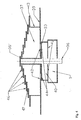
- the heating device has a combustion chamber 20, which can be seen from FIG. 3 to top is completed with a cover 4 made of a refractory material that in turn is covered by a protective cover 21.
- the walls 23 of the combustion chamber 20 are provided with a lining 22 made of refractory material, the wall 23 as a Double jacket is formed, which is flowed through by water, which via connections 24, 25th is dissipatable, the supply over in the top, not shown, area of Double jacket arranged connections is made.
- the Double jacket in the usual way with beads to secure the distance between the both walls of the double jacket and to increase its mechanical strength Mistake.
- a rotating grate 3 is arranged in the combustion chamber 20, which is shown in more detail with reference to FIGS. 4 and 5 will be explained.
- This rotating grate 3 is from a gear motor, not shown driven.
- a primary air duct 1 (FIG. 3) runs beneath the rotating grate 3, on which a blower 26 connected. Furthermore, a drivable ash discharge screw 16 is provided, which in protrudes a space below the rotating grate 3 and is stirred in a nozzle 48.
- a fuel feed screw protrudes into the combustion chamber 20 a pipe through an opening 27 of the combustion chamber 20, not shown is and runs above the rotating grate 3. in the direction of rotation of the rotating grate 3 by one
- An angular amount with respect to this fuel feed screw is a clearing screw (not shown) provided, the wall 23 in a bearing, not shown interspersed with lining.
- This clearing screw runs along the surface lines of the substantially conical rotating grate 3 and serves to clear the burnt out Fuel to convey this in the area of the ash discharge screw 16.
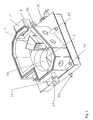
- a burnout chamber 10 is provided, which is arranged parallel to the combustion chamber 20 and connected to it via a train 8, which extends towards the burnout chamber 10 is tapered and surrounded by a double jacket 7, which is used to feed in secondary air serves, air nozzles 6 being provided on the end face facing the burnout space 10 are, which are only partially shown in FIG. 3.
- the burnout chamber 10 has a essentially circular cross-section, the axis of the train 8 essentially in tangential direction to the cross section of the burnout space 10.
- This burnout space 10 is provided with a closable service opening 14 '.
- this service opening 14 ' has a viewing opening arranged in a connecting piece 60.
- an ash chamber 28 is provided, which by a essentially at the mouth of the train 8 into the burnout space 10 separating plate 9 is limited, which extends obliquely downwards.
- This partition plate 9 is double-walled formed (Fig. 3) and serves to supply secondary air to the double jacket 7 of the train 8th
- This secondary air is the partition plate 9 via a secondary air channel 29 (Fig. 3) fed to a blower 30.
- the inside of the double-walled partition 9 is the also extends below the underside of the train 8, via an opening 31 with the inside of the double jacket 7 of the train 8 connected.
- the secondary air flows through it Interior of the double-walled partition plate 9 and the interior of the double jacket 7 of the train 8, whereby the secondary air is heated by the fuel gases flowing through the train 8, before it flows into the burnout chamber 10 via the nozzles 6.
- the burnout chamber 10, the wall of which is also lined with a refractory lining 4 Material is provided, extends through the protective cover 21 upwards.
- the upper region 11 of the burnout chamber 10 is also a heat exchanger arrangement 12 any type and a water-cooled cover 13 are provided.
- the burnout chamber 10, 11 is connected to a chimney (not shown) via a fume cupboard, not shown.
- the rotating grate 3 has eight partition walls 37 which extend radially outward from a sleeve 36 'and the tops thereof are stepped are executed.
- the sleeve 36 ' is rotatably connected to a shaft 36 which is not one shown geared motor is driven.
- the radially outer end faces of the partition walls 37 are connected to one another via an annular wall 43.
- the through the two partitions 37th certain sectors 34 are therefore practically closed and therefore can be practical no air flows from one sector 34 to the adjacent sector 34.
- the partitions 37 are also connected to an ash ring 39, which is ring-shaped arranged openings 42 is provided, between which only relatively narrow webs remain.
- Rust rings 46 are located on the upper stepped edges of the partition walls 37 attached.
- the rust rings 46 which have an upward smaller diameter, are spaced from each other in the vertical direction so that between the individual grate rings 46 Column 47 remain. Primary air can flow into the combustion chamber 20 via this column flow through the solid fuel lying on the grate rings 46.
- the rust rings are usually provided with slots, not shown, to avoid warping to avoid thermal stresses.
- the ash ring 39 which is firmly connected to the ring wall 43 and the sleeve 36 ', rotates in a short distance above a fixed primary air chamber 40 through the top an aperture 33 is completed, which is arranged in an arc Openings 44 is provided.
- the openings 44 of the diaphragm 33 are open arranged a circular arc that is aligned with the circular arc on which the openings 42 of the ash ring 39 are arranged, essentially covers.
- the cross sections of the Openings 44 of the diaphragm 33 decrease continuously (FIG. 4) from the area of the Fuel feed screw (not shown) away against the clearing screw (not shown) to, the openings in the illustrated embodiment extend an angle of approx. 240 °.
- a portion of the aperture 33 is free of Openings 44 held.
- the supply of primary air to the primary air chamber 40 takes place via the primary air duct 1, the primary air chamber 40 on its underside in the area of the primary air duct 1 Breakthroughs 41 has, through which the air can flow.
- Solid fuel e.g. Pellets with the fuel feed screw that protrudes through the opening 27 into the combustion chamber 20, introduced and on the rotating grate 3 applied.
- the fuel is gas due to the prevailing in the combustion chamber 20 Temperatures out and the gases ignite.
- the openings 44 of the diaphragm 33 with the largest cross sections. As a result, a lot of primary air is supplied in this area.
- the sector determined by the partition walls 37 arrives 34 of the rotating grate 3, on which the fuel was applied in areas of Openings 44 of the aperture 33 with smaller cross sections, which makes it slow burning fuel less and less air is supplied, which Fuel in the course of its progressive combustion always essentially optimal is supplied with air, because in the course of the progressive combustion of the Air consumption reduced.
- the aperture 39 no longer has any openings. This means that there is one in the area Sector 34, above which the scraper screw is located, if at all, is only a very small one low air flow, which means that only a few ash parts are entrained.
- the flames and fuel gases flow through the train 8 into the burnout chamber 10, the fuel gases due to the orientation of the train 8 substantially tangential in the Flowing out burnout chamber 10.
- the ash particles contained in the fuel gases are specifically heavier than the gases and are therefore due to the swirl of the flow on the wall of the burnout 10th crowded. Because the gases are in contact with the wall due to the friction If the boundary layer moves much more slowly than towards the center of the gas flow, they fall on the wall of the burnout chamber 10 coming ash parts down into the Ash room 28 and are discharged from it with a discharge screw 50 (FIG. 3).
- the combustion gases are removed by the heat exchanger arrangement 12 and the water-cooled lid 13 heat removed.
- the cooled ones Fuel gases then enter a chimney and are discharged through it.
Landscapes
- Engineering & Computer Science (AREA)
- Mechanical Engineering (AREA)
- General Engineering & Computer Science (AREA)
- Chemical & Material Sciences (AREA)
- Combustion & Propulsion (AREA)
- Physics & Mathematics (AREA)
- Thermal Sciences (AREA)
- Solid-Fuel Combustion (AREA)
Abstract
Description
Claims (8)
- Heizeinrichtung mit einem Brennraum (20), in den eine Brennstoffzufuhr mündet und der über einen im wesentlichen horizontalen Zug (8) mit einem Ausbrennraum (10) verbunden ist, in den mindestens ein Einlass (6) für Sekundärluft und/oder ein Gemisch von Sekundärluft und Brenngasen mündet, dadurch gekennzeichnet, dass der Ausbrennraum (10) vertikal ausgerichtet ist und einen im wesentlichen kreisrunden Querschnitt aufweist, wobei der Einlass (6) tangential in den Ausbrennraum (10) mündet.
- Heizeinrichtung gemäß Anspruch 1, dadurch gekennzeichnet, dass der Einlass (6) im unteren Bereich des Ausbrennraumes (10) angeordnet ist.
- Heizeinrichtung gemäß Anspruch 1 oder 2, dadurch gekennzeichnet, dass der Zug (8) mit einem Doppelmantel (7) ausgebildet ist, dessen Inneres mit Sekundärluft versorgbar ist, wobei an der dem Ausbrennraum (10) zugekehrten Stirnseite Düsen (6) angeordnet sind.
- Heizeinrichtung gemäß Anspruch 3, dadurch gekennzeichnet, dass die Zufuhr von Sekundärluft zum Inneren des Doppelmantels (7) des Zuges (8) über ein doppelwandiges Trennblech (9) erfolgt, das den Brennraum (20) vom Ausbrennraum (10) unterhalb des Zuges (8) trennt.
- Heizeinrichtung gemäß Anspruch 3 oder 4, dadurch gekennzeichnet, dass das doppelwandige Trennblech (9) schräg nach unten geneigt angeordnet ist und einen Ascheraum (28) im Bereich des Ausbrennraumes (10) begrenzt.
- Heizeinrichtung gemäß einem der Ansprüche 1 bis 5, dadurch gekennzeichnet, dass der Zug (8) tangential in den Ausbrennraum (10) mündet.
- Heizeinrichtung gemäß einem der Ansprüche 1 bis 6, dadurch gekennzeichnet, dass der Zug (8) einen sich in Richtung zum Ausbrennraum hin verjüngenden Querschnitt aufweist.
- Heizeinrichtung gemäß einem der Ansprüche 1 bis 7, dadurch gekennzeichnet, dass der Zug (8) als Doppelmantel ausgebildet ist und an dessen dem Ausbrennraum (10) zugekehrten Stirnseite Einlässe (6) für die Sekundärluft und / oder einem Sekundärluft-Brenngasgemisch angeordnet sind.
Applications Claiming Priority (2)
| Application Number | Priority Date | Filing Date | Title |
|---|---|---|---|
| AT7392003A AT412308B (de) | 2003-05-14 | 2003-05-14 | Heizeinrichtung |
| AT2003739 | 2003-05-14 |
Publications (3)
| Publication Number | Publication Date |
|---|---|
| EP1477734A2 true EP1477734A2 (de) | 2004-11-17 |
| EP1477734A3 EP1477734A3 (de) | 2007-05-30 |
| EP1477734B1 EP1477734B1 (de) | 2013-11-13 |
Family
ID=32234888
Family Applications (1)
| Application Number | Title | Priority Date | Filing Date |
|---|---|---|---|
| EP20040450070 Expired - Lifetime EP1477734B1 (de) | 2003-05-14 | 2004-03-29 | Heizeinrichtung |
Country Status (2)
| Country | Link |
|---|---|
| EP (1) | EP1477734B1 (de) |
| AT (1) | AT412308B (de) |
Cited By (6)
| Publication number | Priority date | Publication date | Assignee | Title |
|---|---|---|---|---|
| EP1933092A1 (de) * | 2006-12-13 | 2008-06-18 | Cola S.R.L. | Kohlenpfannenhalter, insbesondere für Öfen |
| FR2917486A1 (fr) * | 2007-06-15 | 2008-12-19 | Ct Internat De Traitement Et D | Procede de gazeification de dechets dans un four a sole tournante, et four pour sa mise en oeuvre |
| CN102128719A (zh) * | 2010-12-13 | 2011-07-20 | 中国航空动力机械研究所 | 扇形回流燃烧室及其对开式燃烧室机匣 |
| DE102008013891B4 (de) * | 2007-03-29 | 2011-07-21 | Windhager Zentralheizung Technik Gmbh | Brennkammer für einen mit Festbrennstoffen beheizbaren Heizkessel |
| CN102330970A (zh) * | 2011-09-20 | 2012-01-25 | 魏广廷 | 锅炉燃烧器 |
| CN103851626A (zh) * | 2014-03-18 | 2014-06-11 | 郑敏 | 一种垃圾燃烧炉 |
Citations (2)
| Publication number | Priority date | Publication date | Assignee | Title |
|---|---|---|---|---|
| DE29605801U1 (de) | 1996-03-28 | 1996-06-27 | Georg Fischer GmbH & Co, 89312 Günzburg | Heizkessel |
| EP1085259A1 (de) | 1999-09-15 | 2001-03-21 | LIGNOTECH Entwicklung von Biomassefeuerungsanlagen GmbH | Vorrichtung zum Verbrennen biogener Brennstoffe |
Family Cites Families (3)
| Publication number | Priority date | Publication date | Assignee | Title |
|---|---|---|---|---|
| NZ210243A (en) * | 1984-11-19 | 1988-01-08 | Waterwide Dev New Zealand Ltd | Extraction zone for solid fuel burner |
| AT402098B (de) * | 1995-02-16 | 1997-01-27 | Georg Fischer Maschinen Und Ke | Heizkessel |
| DE19817885A1 (de) * | 1998-04-22 | 1999-10-28 | Bosch Gmbh Robert | Anordnung zum Wiederaufbauen des Drehmoments einer aufgeladenen Brennkraftmaschine nach einem ASR-Eingriff |
-
2003
- 2003-05-14 AT AT7392003A patent/AT412308B/de not_active IP Right Cessation
-
2004
- 2004-03-29 EP EP20040450070 patent/EP1477734B1/de not_active Expired - Lifetime
Patent Citations (2)
| Publication number | Priority date | Publication date | Assignee | Title |
|---|---|---|---|---|
| DE29605801U1 (de) | 1996-03-28 | 1996-06-27 | Georg Fischer GmbH & Co, 89312 Günzburg | Heizkessel |
| EP1085259A1 (de) | 1999-09-15 | 2001-03-21 | LIGNOTECH Entwicklung von Biomassefeuerungsanlagen GmbH | Vorrichtung zum Verbrennen biogener Brennstoffe |
Cited By (8)
| Publication number | Priority date | Publication date | Assignee | Title |
|---|---|---|---|---|
| EP1933092A1 (de) * | 2006-12-13 | 2008-06-18 | Cola S.R.L. | Kohlenpfannenhalter, insbesondere für Öfen |
| DE102008013891B4 (de) * | 2007-03-29 | 2011-07-21 | Windhager Zentralheizung Technik Gmbh | Brennkammer für einen mit Festbrennstoffen beheizbaren Heizkessel |
| FR2917486A1 (fr) * | 2007-06-15 | 2008-12-19 | Ct Internat De Traitement Et D | Procede de gazeification de dechets dans un four a sole tournante, et four pour sa mise en oeuvre |
| CN102128719A (zh) * | 2010-12-13 | 2011-07-20 | 中国航空动力机械研究所 | 扇形回流燃烧室及其对开式燃烧室机匣 |
| CN102128719B (zh) * | 2010-12-13 | 2012-10-24 | 中国航空动力机械研究所 | 扇形回流燃烧室及其对开式燃烧室机匣 |
| CN102330970A (zh) * | 2011-09-20 | 2012-01-25 | 魏广廷 | 锅炉燃烧器 |
| CN102330970B (zh) * | 2011-09-20 | 2014-11-05 | 魏广廷 | 锅炉燃烧器 |
| CN103851626A (zh) * | 2014-03-18 | 2014-06-11 | 郑敏 | 一种垃圾燃烧炉 |
Also Published As
| Publication number | Publication date |
|---|---|
| EP1477734B1 (de) | 2013-11-13 |
| EP1477734A3 (de) | 2007-05-30 |
| ATA7392003A (de) | 2004-05-15 |
| AT412308B (de) | 2004-12-27 |
Similar Documents
| Publication | Publication Date | Title |
|---|---|---|
| DE69712710T2 (de) | Verfahren zum Blasen von Sauerstoff in einem Etagenofen | |
| DE60209759T2 (de) | Verbrennungsvorrichtung | |
| DE69002605T2 (de) | System für die Behandlung von Müll in geschmolzenem Zustand. | |
| DE2619316C2 (de) | Müllverbrennungsvorrichtung | |
| EP0204176A2 (de) | Brennkammer für eine Wirbelschichtfeuerung | |
| EP0935731B1 (de) | Vergaserheizkessel für feste brennstoffe, insbesondere für holz | |
| EP0007977A1 (de) | Verfahren zum Brennen von stückigem Brenngut sowie Ringschachtofen zu seiner Durchführung | |
| EP1477734A2 (de) | Heizeinrichtung | |
| EP1695009B1 (de) | Vergaserheizkessel für feste brennstoffe, insbesondere für strohballen, mit optimierten abgaswerten | |
| EP1477736B1 (de) | Heizeinrichtung | |
| DE3839381C2 (de) | ||
| EP0473618B1 (de) | Vorrichtung zum verbrennen von bio- und feststoffmassen | |
| EP0210159B1 (de) | Schachtofen zum Brennen von karbonathaltigem, mineralischem Brenngut | |
| EP0636698B1 (de) | Verfahren, Vorrichtung und Behälter zum Einsetzen von vorgewärmten Schrott in einen Schmelzofen zur Stahlerzeugung | |
| EP0905442B1 (de) | Feuerungsanlage | |
| DE1451148B1 (de) | Vorrichtung zum unmittelbaren Wärmetausch im Gegenstrom zwischen einem schüttfähigen Gut und Gasen | |
| DE2427958C3 (de) | Brenner für Wirbelbettöfen | |
| US1298530A (en) | Apparatus for burning powdered fuel. | |
| EP0268000B1 (de) | Sinteranlage | |
| DE2816282C2 (de) | Müllverbrennungsofen mit einem Wirbelbett | |
| DE2828555C3 (de) | Müllverbrennungsofen | |
| DE29707032U1 (de) | Feuerungsanlage | |
| DE613777C (de) | Verfahren und Vorrichtung zur Herstellung von Zement | |
| DE202014105041U1 (de) | Mobile Festbrennstofffeuerungsanlage | |
| DE1451148C (de) | Vorrichtung zum unmittelbaren Warmetausch im Gegenstrom zwischen einem schutt fähigem Gut und Gasen |
Legal Events
| Date | Code | Title | Description |
|---|---|---|---|
| PUAI | Public reference made under article 153(3) epc to a published international application that has entered the european phase |
Free format text: ORIGINAL CODE: 0009012 |
|
| AK | Designated contracting states |
Kind code of ref document: A2 Designated state(s): AT BE BG CH CY CZ DE DK EE ES FI FR GB GR HU IE IT LI LU MC NL PL PT RO SE SI SK TR |
|
| AX | Request for extension of the european patent |
Extension state: AL HR LT LV MK |
|
| PUAL | Search report despatched |
Free format text: ORIGINAL CODE: 0009013 |
|
| AK | Designated contracting states |
Kind code of ref document: A3 Designated state(s): AT BE BG CH CY CZ DE DK EE ES FI FR GB GR HU IE IT LI LU MC NL PL PT RO SE SI SK TR |
|
| AX | Request for extension of the european patent |
Extension state: AL LT LV MK |
|
| 17P | Request for examination filed |
Effective date: 20071128 |
|
| AKX | Designation fees paid |
Designated state(s): AT BE BG CH CY CZ DE DK EE ES FI FR GB GR HU IE IT LI LU MC NL PL PT RO SE SI SK TR |
|
| 17Q | First examination report despatched |
Effective date: 20121008 |
|
| REG | Reference to a national code |
Ref country code: DE Ref legal event code: R079 Ref document number: 502004014432 Country of ref document: DE Free format text: PREVIOUS MAIN CLASS: F23B0005000000 Ipc: F23B0080000000 |
|
| GRAP | Despatch of communication of intention to grant a patent |
Free format text: ORIGINAL CODE: EPIDOSNIGR1 |
|
| RIC1 | Information provided on ipc code assigned before grant |
Ipc: F23L 9/04 20060101ALI20130531BHEP Ipc: F23B 10/02 20110101ALI20130531BHEP Ipc: F23B 80/00 20060101AFI20130531BHEP |
|
| INTG | Intention to grant announced |
Effective date: 20130703 |
|
| GRAS | Grant fee paid |
Free format text: ORIGINAL CODE: EPIDOSNIGR3 |
|
| GRAA | (expected) grant |
Free format text: ORIGINAL CODE: 0009210 |
|
| AK | Designated contracting states |
Kind code of ref document: B1 Designated state(s): AT BE BG CH CY CZ DE DK EE ES FI FR GB GR HU IE IT LI LU MC NL PL PT RO SE SI SK TR |
|
| REG | Reference to a national code |
Ref country code: GB Ref legal event code: FG4D Free format text: NOT ENGLISH |
|
| REG | Reference to a national code |
Ref country code: CH Ref legal event code: EP |
|
| REG | Reference to a national code |
Ref country code: AT Ref legal event code: REF Ref document number: 640732 Country of ref document: AT Kind code of ref document: T Effective date: 20131215 |
|
| REG | Reference to a national code |
Ref country code: IE Ref legal event code: FG4D Free format text: LANGUAGE OF EP DOCUMENT: GERMAN |
|
| REG | Reference to a national code |
Ref country code: DE Ref legal event code: R096 Ref document number: 502004014432 Country of ref document: DE Effective date: 20140102 |
|
| REG | Reference to a national code |
Ref country code: NL Ref legal event code: VDEP Effective date: 20131113 |
|
| PG25 | Lapsed in a contracting state [announced via postgrant information from national office to epo] |
Ref country code: NL Free format text: LAPSE BECAUSE OF FAILURE TO SUBMIT A TRANSLATION OF THE DESCRIPTION OR TO PAY THE FEE WITHIN THE PRESCRIBED TIME-LIMIT Effective date: 20131113 Ref country code: SE Free format text: LAPSE BECAUSE OF FAILURE TO SUBMIT A TRANSLATION OF THE DESCRIPTION OR TO PAY THE FEE WITHIN THE PRESCRIBED TIME-LIMIT Effective date: 20131113 Ref country code: FI Free format text: LAPSE BECAUSE OF FAILURE TO SUBMIT A TRANSLATION OF THE DESCRIPTION OR TO PAY THE FEE WITHIN THE PRESCRIBED TIME-LIMIT Effective date: 20131113 |
|
| PG25 | Lapsed in a contracting state [announced via postgrant information from national office to epo] |
Ref country code: ES Free format text: LAPSE BECAUSE OF FAILURE TO SUBMIT A TRANSLATION OF THE DESCRIPTION OR TO PAY THE FEE WITHIN THE PRESCRIBED TIME-LIMIT Effective date: 20131113 Ref country code: CY Free format text: LAPSE BECAUSE OF FAILURE TO SUBMIT A TRANSLATION OF THE DESCRIPTION OR TO PAY THE FEE WITHIN THE PRESCRIBED TIME-LIMIT Effective date: 20131113 |
|
| PG25 | Lapsed in a contracting state [announced via postgrant information from national office to epo] |
Ref country code: PT Free format text: LAPSE BECAUSE OF FAILURE TO SUBMIT A TRANSLATION OF THE DESCRIPTION OR TO PAY THE FEE WITHIN THE PRESCRIBED TIME-LIMIT Effective date: 20140313 |
|
| PG25 | Lapsed in a contracting state [announced via postgrant information from national office to epo] |
Ref country code: EE Free format text: LAPSE BECAUSE OF FAILURE TO SUBMIT A TRANSLATION OF THE DESCRIPTION OR TO PAY THE FEE WITHIN THE PRESCRIBED TIME-LIMIT Effective date: 20131113 |
|
| REG | Reference to a national code |
Ref country code: DE Ref legal event code: R097 Ref document number: 502004014432 Country of ref document: DE |
|
| PG25 | Lapsed in a contracting state [announced via postgrant information from national office to epo] |
Ref country code: PL Free format text: LAPSE BECAUSE OF FAILURE TO SUBMIT A TRANSLATION OF THE DESCRIPTION OR TO PAY THE FEE WITHIN THE PRESCRIBED TIME-LIMIT Effective date: 20131113 Ref country code: SK Free format text: LAPSE BECAUSE OF FAILURE TO SUBMIT A TRANSLATION OF THE DESCRIPTION OR TO PAY THE FEE WITHIN THE PRESCRIBED TIME-LIMIT Effective date: 20131113 Ref country code: RO Free format text: LAPSE BECAUSE OF FAILURE TO SUBMIT A TRANSLATION OF THE DESCRIPTION OR TO PAY THE FEE WITHIN THE PRESCRIBED TIME-LIMIT Effective date: 20131113 Ref country code: CZ Free format text: LAPSE BECAUSE OF FAILURE TO SUBMIT A TRANSLATION OF THE DESCRIPTION OR TO PAY THE FEE WITHIN THE PRESCRIBED TIME-LIMIT Effective date: 20131113 |
|
| PLBE | No opposition filed within time limit |
Free format text: ORIGINAL CODE: 0009261 |
|
| STAA | Information on the status of an ep patent application or granted ep patent |
Free format text: STATUS: NO OPPOSITION FILED WITHIN TIME LIMIT |
|
| PG25 | Lapsed in a contracting state [announced via postgrant information from national office to epo] |
Ref country code: DK Free format text: LAPSE BECAUSE OF FAILURE TO SUBMIT A TRANSLATION OF THE DESCRIPTION OR TO PAY THE FEE WITHIN THE PRESCRIBED TIME-LIMIT Effective date: 20131113 |
|
| 26N | No opposition filed |
Effective date: 20140814 |
|
| PG25 | Lapsed in a contracting state [announced via postgrant information from national office to epo] |
Ref country code: LU Free format text: LAPSE BECAUSE OF FAILURE TO SUBMIT A TRANSLATION OF THE DESCRIPTION OR TO PAY THE FEE WITHIN THE PRESCRIBED TIME-LIMIT Effective date: 20140329 |
|
| REG | Reference to a national code |
Ref country code: CH Ref legal event code: PL |
|
| GBPC | Gb: european patent ceased through non-payment of renewal fee |
Effective date: 20140329 |
|
| REG | Reference to a national code |
Ref country code: DE Ref legal event code: R097 Ref document number: 502004014432 Country of ref document: DE Effective date: 20140814 |
|
| REG | Reference to a national code |
Ref country code: IE Ref legal event code: MM4A |
|
| PG25 | Lapsed in a contracting state [announced via postgrant information from national office to epo] |
Ref country code: IE Free format text: LAPSE BECAUSE OF NON-PAYMENT OF DUE FEES Effective date: 20140329 Ref country code: CH Free format text: LAPSE BECAUSE OF NON-PAYMENT OF DUE FEES Effective date: 20140331 Ref country code: LI Free format text: LAPSE BECAUSE OF NON-PAYMENT OF DUE FEES Effective date: 20140331 Ref country code: GB Free format text: LAPSE BECAUSE OF NON-PAYMENT OF DUE FEES Effective date: 20140329 |
|
| PG25 | Lapsed in a contracting state [announced via postgrant information from national office to epo] |
Ref country code: SI Free format text: LAPSE BECAUSE OF FAILURE TO SUBMIT A TRANSLATION OF THE DESCRIPTION OR TO PAY THE FEE WITHIN THE PRESCRIBED TIME-LIMIT Effective date: 20131113 |
|
| REG | Reference to a national code |
Ref country code: FR Ref legal event code: PLFP Year of fee payment: 12 |
|
| PG25 | Lapsed in a contracting state [announced via postgrant information from national office to epo] |
Ref country code: IT Free format text: LAPSE BECAUSE OF FAILURE TO SUBMIT A TRANSLATION OF THE DESCRIPTION OR TO PAY THE FEE WITHIN THE PRESCRIBED TIME-LIMIT Effective date: 20131113 |
|
| PGFP | Annual fee paid to national office [announced via postgrant information from national office to epo] |
Ref country code: DE Payment date: 20150324 Year of fee payment: 12 |
|
| PGFP | Annual fee paid to national office [announced via postgrant information from national office to epo] |
Ref country code: AT Payment date: 20150316 Year of fee payment: 12 Ref country code: FR Payment date: 20150319 Year of fee payment: 12 |
|
| PG25 | Lapsed in a contracting state [announced via postgrant information from national office to epo] |
Ref country code: BG Free format text: LAPSE BECAUSE OF FAILURE TO SUBMIT A TRANSLATION OF THE DESCRIPTION OR TO PAY THE FEE WITHIN THE PRESCRIBED TIME-LIMIT Effective date: 20131113 Ref country code: MC Free format text: LAPSE BECAUSE OF FAILURE TO SUBMIT A TRANSLATION OF THE DESCRIPTION OR TO PAY THE FEE WITHIN THE PRESCRIBED TIME-LIMIT Effective date: 20131113 |
|
| PG25 | Lapsed in a contracting state [announced via postgrant information from national office to epo] |
Ref country code: GR Free format text: LAPSE BECAUSE OF FAILURE TO SUBMIT A TRANSLATION OF THE DESCRIPTION OR TO PAY THE FEE WITHIN THE PRESCRIBED TIME-LIMIT Effective date: 20140214 |
|
| PG25 | Lapsed in a contracting state [announced via postgrant information from national office to epo] |
Ref country code: BE Free format text: LAPSE BECAUSE OF FAILURE TO SUBMIT A TRANSLATION OF THE DESCRIPTION OR TO PAY THE FEE WITHIN THE PRESCRIBED TIME-LIMIT Effective date: 20140331 Ref country code: HU Free format text: LAPSE BECAUSE OF FAILURE TO SUBMIT A TRANSLATION OF THE DESCRIPTION OR TO PAY THE FEE WITHIN THE PRESCRIBED TIME-LIMIT; INVALID AB INITIO Effective date: 20040329 Ref country code: TR Free format text: LAPSE BECAUSE OF FAILURE TO SUBMIT A TRANSLATION OF THE DESCRIPTION OR TO PAY THE FEE WITHIN THE PRESCRIBED TIME-LIMIT Effective date: 20131113 |
|
| REG | Reference to a national code |
Ref country code: DE Ref legal event code: R119 Ref document number: 502004014432 Country of ref document: DE |
|
| REG | Reference to a national code |
Ref country code: AT Ref legal event code: MM01 Ref document number: 640732 Country of ref document: AT Kind code of ref document: T Effective date: 20160329 |
|
| REG | Reference to a national code |
Ref country code: FR Ref legal event code: ST Effective date: 20161130 |
|
| PG25 | Lapsed in a contracting state [announced via postgrant information from national office to epo] |
Ref country code: FR Free format text: LAPSE BECAUSE OF NON-PAYMENT OF DUE FEES Effective date: 20160331 Ref country code: DE Free format text: LAPSE BECAUSE OF NON-PAYMENT OF DUE FEES Effective date: 20161001 |
|
| PG25 | Lapsed in a contracting state [announced via postgrant information from national office to epo] |
Ref country code: AT Free format text: LAPSE BECAUSE OF NON-PAYMENT OF DUE FEES Effective date: 20160329 |