EP1477436A1 - Conveying apparatus with carriers - Google Patents
Conveying apparatus with carriers Download PDFInfo
- Publication number
- EP1477436A1 EP1477436A1 EP04011070A EP04011070A EP1477436A1 EP 1477436 A1 EP1477436 A1 EP 1477436A1 EP 04011070 A EP04011070 A EP 04011070A EP 04011070 A EP04011070 A EP 04011070A EP 1477436 A1 EP1477436 A1 EP 1477436A1
- Authority
- EP
- European Patent Office
- Prior art keywords
- cross
- link
- links
- deck
- linking mechanism
- Prior art date
- Legal status (The legal status is an assumption and is not a legal conclusion. Google has not performed a legal analysis and makes no representation as to the accuracy of the status listed.)
- Granted
Links
- 239000000969 carrier Substances 0.000 title abstract description 24
- 230000007246 mechanism Effects 0.000 claims abstract description 72
- 238000004132 cross linking Methods 0.000 claims abstract description 71
- 230000003028 elevating effect Effects 0.000 abstract description 4
- 230000005484 gravity Effects 0.000 description 3
- 238000005096 rolling process Methods 0.000 description 2
Images


Classifications
-
- B—PERFORMING OPERATIONS; TRANSPORTING
- B66—HOISTING; LIFTING; HAULING
- B66F—HOISTING, LIFTING, HAULING OR PUSHING, NOT OTHERWISE PROVIDED FOR, e.g. DEVICES WHICH APPLY A LIFTING OR PUSHING FORCE DIRECTLY TO THE SURFACE OF A LOAD
- B66F7/00—Lifting frames, e.g. for lifting vehicles; Platform lifts
- B66F7/06—Lifting frames, e.g. for lifting vehicles; Platform lifts with platforms supported by levers for vertical movement
- B66F7/065—Scissor linkages, i.e. X-configuration
-
- B—PERFORMING OPERATIONS; TRANSPORTING
- B65—CONVEYING; PACKING; STORING; HANDLING THIN OR FILAMENTARY MATERIAL
- B65G—TRANSPORT OR STORAGE DEVICES, e.g. CONVEYORS FOR LOADING OR TIPPING, SHOP CONVEYOR SYSTEMS OR PNEUMATIC TUBE CONVEYORS
- B65G17/00—Conveyors having an endless traction element, e.g. a chain, transmitting movement to a continuous or substantially-continuous load-carrying surface or to a series of individual load-carriers; Endless-chain conveyors in which the chains form the load-carrying surface
- B65G17/30—Details; Auxiliary devices
- B65G17/48—Controlling attitudes of load-carriers during movement
-
- B—PERFORMING OPERATIONS; TRANSPORTING
- B65—CONVEYING; PACKING; STORING; HANDLING THIN OR FILAMENTARY MATERIAL
- B65G—TRANSPORT OR STORAGE DEVICES, e.g. CONVEYORS FOR LOADING OR TIPPING, SHOP CONVEYOR SYSTEMS OR PNEUMATIC TUBE CONVEYORS
- B65G21/00—Supporting or protective framework or housings for endless load-carriers or traction elements of belt or chain conveyors
- B65G21/20—Means incorporated in, or attached to, framework or housings for guiding load-carriers, traction elements or loads supported on moving surfaces
- B65G21/22—Rails or the like engaging sliding elements or rollers attached to load-carriers or traction elements
Definitions
- the present invention relates to a conveying apparatus including a car type conveyor or a slat conveyor and fitted with carriers.
- the conveying apparatus disclosed in Publication No. H7-157039 includes a slat conveyor extending along a running track.
- the slat conveyor is fitted with elevators at intervals along it.
- the elevators can move vertically relative to the slat conveyor, and each of them directly supports a carrier.
- a cam rail is fixed relative to the slat conveyor and lifts the elevators.
- the cam rail makes it possible to keep the carriers at an elevated position in a limited section of the running track.
- the strokes of the elevators which equal the height of the cam rail, equal the lift of the carriers. Accordingly, a greater lift of the carriers require the cam rail to be higher.
- the higher rail requires a higher space for it, consequently raising the level of the carriers relative to the floor. As a result, this conveying apparatus is not suitable for a low floor structure.
- the conveying apparatus disclosed in Publication No. H7-172538 includes a slat conveyor extending along a running track.
- This slat conveyor supports cross-linking mechanisms at intervals along it.
- Each of the cross-linking mechanisms supports a carrier and includes pairs of links, which are connected together by a fulcrum shaft.
- the slat conveyor is fitted with elevators, which can move vertically relative to it, and each of which supports one of the fulcrum shafts of the cross-linking mechanisms.
- a cam rail is fixed relative to the slat conveyor and lifts the elevators, which elevate the carriers.
- H7-157039 makes it possible to increase the lift of the carriers relative to the strokes of the elevators, which equal the height of the cam rail. Nevertheless, a greater lift of the carriers require the cam rail to be correspondingly higher. As a result, the conveying apparatus is still unsuitable for a low floor structure.
- the object of the present invention is to provide a conveying apparatus including carriers that solves the foregoing problems.
- a conveying apparatus includes a cam rail and a carriage.
- the cam rail extends along a horizontal running track, along which the carriage runs.
- the carriage includes a deck, on which an erectable cross-linking mechanism is mounted.
- the cross-linking mechanism supports and vertically moves a carrier.
- the cross-linking mechanism includes a first link and a second link. One end of the first link is supported on a horizontal pivot axis adjacent to and fixed relative to the deck.
- the first and second links are connected together at their middle points by a fulcrum parallel with the pivot axis.
- the first link is fitted with a driven member between the fulcrum and the pivot axis.
- An elevator is supported vertically movably by the deck.
- the elevator includes a bearing member fixed to its top and a cam follower supported by its bottom.
- the driven member is supported by the bearing member horizontally movably relative to it.
- the cam follower can follow the cam rail, lifting the elevator, so that the cross-linking mechanism erects to elevate the carrier.
- the conveying apparatus makes it possible to sufficiently increase the lift of the carrier relative to the strokes of the elevator, in comparison with the prior art where an elevator elevates the fulcrum shaft connecting the links of a cross-linking mechanism. In other words, it is possible to secure a necessary lift of the carrier without increasing the height of the cam rail, which equals the elevator strokes.
- the conveying apparatus may be a friction drive type apparatus for a low floor structure, which includes a deck in the form of a plate having frictional surfaces on both sides, as will be described below in the description of embodiments of the present invention.
- the cam rail can be laid without obstruction in the low space between a floor and the carriage that runs at a low level over the floor. The thus laid rail can easily lift the carrier to a desired level.
- the driven member of the cross-linking mechanism is supported by the bearing member at the top of the elevator horizontally movably relative to it. Consequently, the elevator can be supported vertically movably, and the cam rail needs to merely lift it. This makes it possible to simplify the whole structure of the carrier driving mechanism of the carriage.
- a conveying apparatus includes a cam rail and a carriage.
- the cam rail extends along a horizontal running track, along which the carriage runs.
- the carriage includes a deck, on which an erectable cross-linking mechanism is mounted.
- the cross-linking mechanism supports and vertically moves a carrier.
- the cross-linking mechanism includes a first link, a second link, a third link, and a fourth link.
- One end of the first link and one end of the second link are supported by a pivot axis, which is adjacent to and fixed to the deck.
- Middle points of the four links are connected together by a fulcrum shaft, which is parallel with the pivot axis.
- the first and second links are connected together by a connecting shaft, which is parallel with the pivot axis and positioned between the fulcrum and pivot shafts.
- the connecting shaft is fitted with a driven member.
- An elevator is supported vertically movably by the deck.
- the elevator includes a bearing member fixed to its top and a cam follower supported by its bottom.
- the driven member is supported by the bearing member horizontally movably relative to it.
- the cam follower can follow the cam rail, lifting the elevator, so that the cross-linking mechanism erects to elevate the carrier.
- the first and third links pair with each other.
- the second and fourth links pair with each other.
- the two pairs of links can be elevated by the single elevator and cooperate stably with each other.
- the bearing member of the elevator may have a guide groove formed in it
- the driven member of the cross-linking mechanism may be a roller rotatable on an axis parallel with the horizontal pivot axis.
- the roller engages with the guide groove rollably and movably.
- the guide groove and the roller cooperate to transmit the elevating operation of the elevator smoothly and reliably to the cross-linking mechanism. Even if the elevator includes a vertical columnar shaft that can rotate on its own axis, the roller serves to keep the elevator from rotating.
- a conveying apparatus includes a pair of cam rails and a carriage.
- the cam rails extend along a horizontal running track, along which the carriage runs.
- the carriage includes a deck, on which a front erectable cross-linking mechanism and a rear erectable cross-linking mechanism are mounted.
- Each of the cross-linking mechanisms is spaced from the other along the running track.
- Each of the cross-linking mechanisms supports and vertically moves a carrier.
- Each of the two cross-linking mechanisms includes a first link and a second link, each of which extends on a vertical plane perpendicular to the running track. One end of the first link is supported on a horizontal pivot axis, which is adjacent to and fixed relative to the deck.
- Middle points of the two links are connected together by a horizontal fulcrum.
- the pivot axis and the fulcrum are parallel with the running track.
- the first link is fitted with a driven member between the pivot axis and the fulcrum.
- a pair of elevators is supported vertically movably by the deck.
- Each of the elevators includes a bearing member fixed to its top and a cam follower supported by its bottom.
- Each of the driven members of the two cross-linking mechanisms is supported by one of the bearing members of the two elevators horizontally movably relative to it.
- Each of the cam followers of the two elevators can follow one of the cam rails, lifting the associated elevator, so that the associated cross-linking mechanism erects to elevate the associated carrier.
- the two driven members are offset from each other perpendicularly to the running track.
- the two cam rails are offset longitudinally from each other so as to lift the two elevators in synchronism.
- the front and rear cross-linking mechanisms can stably support the carriers, which may support a work long in parallel with the running track. These cross-linking mechanisms can be erected in synchronism so as to elevate the carriers safely in parallel.
- a conveying apparatus includes a cam rail and a carriage.
- the cam rail extends along a horizontal running track, along which the carriage runs.
- the carriage includes a deck, on which an erectable cross-linking mechanism is mounted.
- the cross-linking mechanism supports and vertically moves a carrier.
- the cross-linking mechanism includes at least a first link, a second link, a third link and a fourth link.
- One end of the first link is supported on a horizontal pivot axis, which is adjacent to and fixed relative to the deck.
- the other end of the first link is connected pivotably with one end of the third link.
- One end of the second link is connected pivotably with one end of the fourth link.
- Middle points of the first and second links are connected together by a lower fulcrum, which is parallel with the pivot axis.
- Middle points of the third and fourth links are connected together by an upper fulcrum, which is parallel with the pivot axis.
- the first link is fitted with a driven member between the pivot axis and the lower fulcrum.
- An elevator is supported vertically movably by the deck.
- the elevator includes a bearing member fixed to its top and a cam follower supported by its bottom.
- the driven member is supported by the bearing member horizontally movably relative to it.
- the cam follower can follow the cam rail, lifting the elevator, so that the cross-linking mechanism erects to elevate the carrier.
- the first and second links of this conveying apparatus pair with each other as a lower pair of links.
- the third and fourth links of the apparatus pair with each other as an upper pair of links, which is connected vertically with the lower pair.
- the vertically connected pairs of links make it possible to multiply the lift of the carrier by the number of pairs of links. Accordingly, the conveying apparatus is effective in conveying a work requiring a great lift.
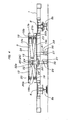
- a conveying apparatus embodying the present invention includes a plurality of carriages, one of which is shown in Figs. 1 - 7. With reference to Figs. 1 - 3, each of the carriages includes a deck 1 in the form of a horizontal plate.
- the deck 1 is rectangular with both sides longer than both ends.
- the deck 1 has parallel frictional surfaces 8a and 8b formed on its right and left sides, respectively.
- a front cross-linking mechanism 3 and a rear cross-linking mechanism 4 are mounted on the deck 1 and spaced from each other longitudinally of it.
- a front horizontal carrier 2A and a rear horizontal carrier 2B rest on the cross-linking mechanisms 3 and 4, respectively, and support a workpiece W on them.
- the deck 1 is supported by a front pair and a rear pair of wheel units 6.
- each left wheel unit 6 includes a pair of antivibration rollers for rolling on both sides of the left guide rail 5b.
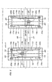
- a plurality of deck drivers 7, one of which is shown in Figs. 2 and 3, are fixed on the floor at intervals along the running track and frictionally drive the decks 1 of the carriages.
- Each deck driver 7 includes a frictional wheel 9 and a motor 10 located on the right side of the running track and a back-up roller 11 located on the left side.
- the frictional wheel 9 and back-up roller 11 cooperate for compressive contact with the frictional surfaces 8a and 8b, respectively, of the deck 1 located between them.
- the motor 10 drives the frictional wheel 9 to move the deck 1 forward at a constant speed along the running track.
- the intervals at which the deck drivers 7 are located may be roughly equal to or slightly shorter than the length of each deck 1 so that the deck being driven by each deck driver 7 except the last one can engage successively with the next driver. This enables the carriages to run at optional intervals and the constant speed.
- the driver interval may be sufficiently longer than the deck length so that the deck 1 being driven by each deck driver 7 can successively push the preceding deck having disengaged from this driver.
- each cross-linking mechanism 3 or 4 is bilaterally symmetrical, and the cross-linking mechanisms 3 and 4 of each of the carriages are spaced from each other longitudinally of the associated deck 1.
- Each cross-linking mechanism 3 or 4 includes a pair of intercrossed links 12 and a pair of links 13.
- Each pair of intercrossed links 12 or 13 is spaced from the other longitudinally of the deck 1.
- the inner links 14a and outer links 14b of the pairs 12 and 13 are equal in length.
- Each link 14a or 14b extends on a vertical plane lateral of the deck 1.
- the four links 14a and 14b of each cross-linking mechanism 3 or 4 are connected together at their middle points by a horizontal fulcrum shaft 15.
- the lower ends of the inner links 14a of each cross-linking mechanism 3 or 4 are supported through a fixed horizontal pivot shaft 16 by a pair of bearings 16a and 16b, which are fixed on the deck 1.
- the upper ends of the inner links 14a support a pair of upper rollers 18a and 18b through a horizontal roller shaft 19.
- the upper rollers 18a and 18b engage rollably and movably with a front guide rail 17a and a rear guide rail 17b, respectively, which are U-shaped in cross section.
- the guide rails 17a and 17b are fixed to the bottom of the associated carrier 2A or 2B and extend laterally of the deck 1.
- the upper ends of the outer links 14b of each cross-linking mechanism 3 or 4 are supported through a horizontal fixed pivot shaft 20 by a pair of bearings 20a and 20b, which are fixed to the bottom of the associated carrier 2A or 2B.
- the lower ends of the outer links 14 b support a pair of lower rollers 22a and 22b through a horizontal roller shaft 23.
- the lower rollers 22a and 22b engage rollably and movably with a front guide rail 21a and a rear guide rail 21b, respectively, which are U-shaped in cross section.
- the guide rails 21a and 21b are fixed to the top of the deck 1 and extend laterally of it.
- the horizontal shafts 15, 16, 19, 20 and 23 extend longitudinally of the deck 1.
- each cross-linking mechanism 3 or 4 is bilaterally symmetrical.
- the fulcrum shafts 15 of the cross-linking mechanisms 3 and 4 of each of the carriages can move on a vertical plane extending through the center of the associated deck 1 longitudinally of it.
- the lower pivot shafts 16 of the associated cross-linking mechanisms 3 and 4 are positioned on the right and left sides, respectively, of the deck 1.
- the inner links 14a of each cross-linking mechanism 3 or 4 are connected together by a connecting shaft 24, which is positioned between the associated shafts 15 and 16 and parallel with them.
- the connecting shaft 24 has a middle portion small in diameter, which supports a driven member 25 (roller 26).
- the driven members 26 of the cross-linking mechanisms 3 and 4 of each of the carriages are positioned on the right and left sides, respectively, of the associated deck 1.
- Each deck 1 is fitted with a front elevator 27 and a rear elevator 28 for elevating the driven members 26 of the associated cross-linking mechanisms 3 and 4, respectively.
- the elevators 27 and 28 comprise vertical slide rods 30 and 31, bearing members 32 and 33, and cam followers 34 and 35, respectively.
- Each deck 1 is also fitted with two slide guides 29 fixed to it and extending through it each under one driven member 26.
- Each slide rod 30 or 31 is supported by the slide guide 29 under the associated driven member 26 and can vertically slide through this guide.
- the bearing members 32 and 33 are fixed to the tops of the slide rods 30 and 31, respectively, and have guide grooves 32a and 33a, respectively, formed in their tops.
- Each driven member 26 engages rollably and movably with the associated guide groove 32a or 33a.
- the cam followers 34 and 35 are rollers supporting the bottoms of the slide rods 30 and 31, respectively.
- a right cam rail 36 and a left cam rail 37 lie between the guide rails 5a and 5b on the floor and extend in parallel with them. While each of the carriages is running along a limited section (not shown) of the running track, its cam followers 34 and 35 roll on the cam rails 36 and 37, respectively, lifting the associated elevators 27 and 28, respectively.
- the cam rails 36 and 37 are offset longitudinally from each other by the distance longitudinal of the deck 1 between the elevators 27 and 28 of each of the carriages so that the elevators can be lifted in synchronism.
- the deck drivers 7 move the carriages at the constant speed along the guide rails 5a and 5b. While each of the carriages is running outside the limited section of the running track, as shown in Fig. 4 etc., its carriers 2A and 2B are lowered to their lower limit positions by gravity. In the meantime, the associated elevators 27 and 28 are supported at their lower limit positions by the associated slide guides 29, with the associated cam followers 34 and 35 out of contact with the floor. Accordingly, the work W on these carriers 2A and 2B is in its lower limit position relative to the associated deck 1.
- the work W is shown as supported directly on the carriers 2A and 2B of one of the carriages. Actually, however, the work W is placed on a suitable support attachment, which is supported on the carriers 2A and 2B.
- the cross-linking mechanisms 3 and 4 of each of the carriages might support a long carrier in place of two carriers 2A and 2B.
- the front and rear cross-linking mechanisms 3 and 4 of each of the carriages erect in synchronism, so that the associated carriers 2A and 2B are elevated in parallel to their upper limit positions, with their levels kept equal.
- the position of the work W on the carriers 2A and 2B is changed over to its upper limit.
- the carriage is running along the limited section of the running track, it is possible to elevate the work W automatically to the position suitable for the working on the work in this section.
- the decks 1 might be driven by a chain conveyor along an endless circulation track, which includes a conveying path extending over the floor and a return path extending under the floor.
- a pair of cam rails extend along the return path and are U-shaped in cross section.
- the cam followers 34 and 35 of the elevators might be adapted for engagement with the U-rails.
- the bearing members 32 and 33 of the elevators might be rails U-shaped in cross section, and the driven members 26 of the cross-linking mechanisms might be adapted for engagement with these rails. While the carriages are running along the return path, the carriers 2A and 2B would hang down and could be elevated toward the floor.
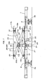
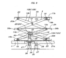
- Fig. 8 shows a carriage of another conveying apparatus embodying the present invention.
- the carriage includes a pair of cross-linking mechanisms 3 and 4, each of which includes two lower pairs of intercrossed links 12A and 13A and two upper pairs of intercrossed links 12B and 13B.
- the lower pairs of intercrossed links 12A and 13A are identical with the pairs of intercrossed links 12 and 13, respectively, of the foregoing embodiment.
- the upper pairs of intercrossed links 12B and 13B are substantially identical with the pairs of intercrossed links 12 and 13, respectively.
- the upper ends of the outer links 14b of the lower pairs 12A and 13A are connected pivotally with the lower ends of the inner links 14a of the upper pairs 12B and 13B by a fulcrum shaft 38a.
- the upper ends of the inner links 14a of the lower pairs 12A and 13A are connected pivotally with the lower ends of the outer links 14b of the upper pairs 12B and 13B by a fulcrum shaft 38b.
- the fulcrum shafts 38a and 38b are identical with the fulcrum shafts 15 of the foregoing embodiment.
- the lower pairs of intercrossed links 12A and 13A support a driven member 25.
- the upper pairs of intercrossed links 12B and 13B support a carrier 2A or 2B.
- Each cross-linking mechanism 3 or 4 of this carriage might include three or more vertically connected sets of links.
Landscapes
- Engineering & Computer Science (AREA)
- Mechanical Engineering (AREA)
- Life Sciences & Earth Sciences (AREA)
- Geology (AREA)
- Structural Engineering (AREA)
- Intermediate Stations On Conveyors (AREA)
- Forklifts And Lifting Vehicles (AREA)
- Formation And Processing Of Food Products (AREA)
- Automobile Manufacture Line, Endless Track Vehicle, Trailer (AREA)
Abstract
Description
- The present invention relates to a conveying apparatus including a car type conveyor or a slat conveyor and fitted with carriers.
- Conveying apparatus of this type are disclosed in Japanese Unexamined Patent Publication Nos. H7-157039 and H7-172538, for example. Each of these apparatus vertically moves carriers by means of a cam rail extending along a running track, not by means of cylinder units or other actuators, each of which might be fitted to one of the plates.
- The conveying apparatus disclosed in Publication No. H7-157039 includes a slat conveyor extending along a running track. The slat conveyor is fitted with elevators at intervals along it. The elevators can move vertically relative to the slat conveyor, and each of them directly supports a carrier. A cam rail is fixed relative to the slat conveyor and lifts the elevators. The cam rail makes it possible to keep the carriers at an elevated position in a limited section of the running track. The strokes of the elevators, which equal the height of the cam rail, equal the lift of the carriers. Accordingly, a greater lift of the carriers require the cam rail to be higher. The higher rail requires a higher space for it, consequently raising the level of the carriers relative to the floor. As a result, this conveying apparatus is not suitable for a low floor structure.
- The conveying apparatus disclosed in Publication No. H7-172538 includes a slat conveyor extending along a running track. This slat conveyor supports cross-linking mechanisms at intervals along it. Each of the cross-linking mechanisms supports a carrier and includes pairs of links, which are connected together by a fulcrum shaft. The slat conveyor is fitted with elevators, which can move vertically relative to it, and each of which supports one of the fulcrum shafts of the cross-linking mechanisms. A cam rail is fixed relative to the slat conveyor and lifts the elevators, which elevate the carriers. This conveying apparatus, as compared with the apparatus disclosed in Publication No. H7-157039, makes it possible to increase the lift of the carriers relative to the strokes of the elevators, which equal the height of the cam rail. Nevertheless, a greater lift of the carriers require the cam rail to be correspondingly higher. As a result, the conveying apparatus is still unsuitable for a low floor structure.
- The object of the present invention is to provide a conveying apparatus including carriers that solves the foregoing problems.
- A conveying apparatus according to one aspect of the present invention includes a cam rail and a carriage. The cam rail extends along a horizontal running track, along which the carriage runs. The carriage includes a deck, on which an erectable cross-linking mechanism is mounted. The cross-linking mechanism supports and vertically moves a carrier. The cross-linking mechanism includes a first link and a second link. One end of the first link is supported on a horizontal pivot axis adjacent to and fixed relative to the deck. The first and second links are connected together at their middle points by a fulcrum parallel with the pivot axis. The first link is fitted with a driven member between the fulcrum and the pivot axis. An elevator is supported vertically movably by the deck. The elevator includes a bearing member fixed to its top and a cam follower supported by its bottom. The driven member is supported by the bearing member horizontally movably relative to it. The cam follower can follow the cam rail, lifting the elevator, so that the cross-linking mechanism erects to elevate the carrier.
- This conveying apparatus makes it possible to sufficiently increase the lift of the carrier relative to the strokes of the elevator, in comparison with the prior art where an elevator elevates the fulcrum shaft connecting the links of a cross-linking mechanism. In other words, it is possible to secure a necessary lift of the carrier without increasing the height of the cam rail, which equals the elevator strokes. The conveying apparatus may be a friction drive type apparatus for a low floor structure, which includes a deck in the form of a plate having frictional surfaces on both sides, as will be described below in the description of embodiments of the present invention. In this case, the cam rail can be laid without obstruction in the low space between a floor and the carriage that runs at a low level over the floor. The thus laid rail can easily lift the carrier to a desired level.
- As stated above, the driven member of the cross-linking mechanism is supported by the bearing member at the top of the elevator horizontally movably relative to it. Consequently, the elevator can be supported vertically movably, and the cam rail needs to merely lift it. This makes it possible to simplify the whole structure of the carrier driving mechanism of the carriage.
- A conveying apparatus according to another aspect of the present invention includes a cam rail and a carriage. The cam rail extends along a horizontal running track, along which the carriage runs. The carriage includes a deck, on which an erectable cross-linking mechanism is mounted. The cross-linking mechanism supports and vertically moves a carrier. The cross-linking mechanism includes a first link, a second link, a third link, and a fourth link. One end of the first link and one end of the second link are supported by a pivot axis, which is adjacent to and fixed to the deck. Middle points of the four links are connected together by a fulcrum shaft, which is parallel with the pivot axis. The first and second links are connected together by a connecting shaft, which is parallel with the pivot axis and positioned between the fulcrum and pivot shafts. The connecting shaft is fitted with a driven member. An elevator is supported vertically movably by the deck. The elevator includes a bearing member fixed to its top and a cam follower supported by its bottom. The driven member is supported by the bearing member horizontally movably relative to it. The cam follower can follow the cam rail, lifting the elevator, so that the cross-linking mechanism erects to elevate the carrier.
- The first and third links pair with each other. The second and fourth links pair with each other. The two pairs of links can be elevated by the single elevator and cooperate stably with each other.
- In each of the conveying apparatus, the bearing member of the elevator may have a guide groove formed in it, and the driven member of the cross-linking mechanism may be a roller rotatable on an axis parallel with the horizontal pivot axis. The roller engages with the guide groove rollably and movably. The guide groove and the roller cooperate to transmit the elevating operation of the elevator smoothly and reliably to the cross-linking mechanism. Even if the elevator includes a vertical columnar shaft that can rotate on its own axis, the roller serves to keep the elevator from rotating.
- A conveying apparatus according to still another aspect of the present invention includes a pair of cam rails and a carriage. The cam rails extend along a horizontal running track, along which the carriage runs. The carriage includes a deck, on which a front erectable cross-linking mechanism and a rear erectable cross-linking mechanism are mounted. Each of the cross-linking mechanisms is spaced from the other along the running track. Each of the cross-linking mechanisms supports and vertically moves a carrier. Each of the two cross-linking mechanisms includes a first link and a second link, each of which extends on a vertical plane perpendicular to the running track. One end of the first link is supported on a horizontal pivot axis, which is adjacent to and fixed relative to the deck. Middle points of the two links are connected together by a horizontal fulcrum. The pivot axis and the fulcrum are parallel with the running track. The first link is fitted with a driven member between the pivot axis and the fulcrum. A pair of elevators is supported vertically movably by the deck. Each of the elevators includes a bearing member fixed to its top and a cam follower supported by its bottom. Each of the driven members of the two cross-linking mechanisms is supported by one of the bearing members of the two elevators horizontally movably relative to it. Each of the cam followers of the two elevators can follow one of the cam rails, lifting the associated elevator, so that the associated cross-linking mechanism erects to elevate the associated carrier. The two driven members are offset from each other perpendicularly to the running track. The two cam rails are offset longitudinally from each other so as to lift the two elevators in synchronism.
- The front and rear cross-linking mechanisms can stably support the carriers, which may support a work long in parallel with the running track. These cross-linking mechanisms can be erected in synchronism so as to elevate the carriers safely in parallel.
- A conveying apparatus according to a further aspect of the present invention includes a cam rail and a carriage. The cam rail extends along a horizontal running track, along which the carriage runs. The carriage includes a deck, on which an erectable cross-linking mechanism is mounted. The cross-linking mechanism supports and vertically moves a carrier. The cross-linking mechanism includes at least a first link, a second link, a third link and a fourth link. One end of the first link is supported on a horizontal pivot axis, which is adjacent to and fixed relative to the deck. The other end of the first link is connected pivotably with one end of the third link. One end of the second link is connected pivotably with one end of the fourth link. Middle points of the first and second links are connected together by a lower fulcrum, which is parallel with the pivot axis. Middle points of the third and fourth links are connected together by an upper fulcrum, which is parallel with the pivot axis. The first link is fitted with a driven member between the pivot axis and the lower fulcrum. An elevator is supported vertically movably by the deck. The elevator includes a bearing member fixed to its top and a cam follower supported by its bottom. The driven member is supported by the bearing member horizontally movably relative to it. The cam follower can follow the cam rail, lifting the elevator, so that the cross-linking mechanism erects to elevate the carrier.
- The first and second links of this conveying apparatus pair with each other as a lower pair of links. The third and fourth links of the apparatus pair with each other as an upper pair of links, which is connected vertically with the lower pair. With respect to the stroke of the elevator, the vertically connected pairs of links make it possible to multiply the lift of the carrier by the number of pairs of links. Accordingly, the conveying apparatus is effective in conveying a work requiring a great lift.
-
- Fig. 1 is a partially broken side view of part of a conveying apparatus according to one embodiment of the present invention, showing a carriage just in the rear of the limited section of a running track.
- Fig. 2 is a top plan of part of the conveying apparatus, showing the carriage as shown in Fig. 1 and a deck driver.
- Fig. 3 is a front view of the conveying apparatus, showing the carriage as shown in Fig. 1.
- Fig. 4 is an enlarged lateral cross section of the conveying apparatus, showing the carriage as shown in Fig. 1.
- Fig. 5 is an enlarged, partially broken top plan of part of the conveying apparatus, showing a front cross-linking mechanism and a rear cross-linking mechanism.
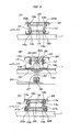
- Fig. 6A is an enlarged longitudinal cross section of part of the conveying apparatus, showing the ends of links of a cross-linking mechanism that are adjacent to the associated pivot shafts.
- Fig. 6B is an enlarged longitudinal cross section of part of the conveying apparatus, showing an elevator etc.
- Fig. 6C is an enlarged longitudinal cross section of part of the conveying apparatus, showing the sliding ends of links of a cross-linking mechanism.
- Fig. 7 is an enlarged lateral cross section of the conveying apparatus, showing a carrier elevated from its lower limit position shown in Fig. 4 to its upper limit position.
- Fig. 8 is a lateral cross section of part of a conveying apparatus according to another embodiment of the present invention, showing a carrier elevated to its upper limit position.
-
- A conveying apparatus embodying the present invention includes a plurality of carriages, one of which is shown in Figs. 1 - 7. With reference to Figs. 1 - 3, each of the carriages includes a
deck 1 in the form of a horizontal plate. Thedeck 1 is rectangular with both sides longer than both ends. Thedeck 1 has parallelfrictional surfaces front cross-linking mechanism 3 and arear cross-linking mechanism 4 are mounted on thedeck 1 and spaced from each other longitudinally of it. A fronthorizontal carrier 2A and a rearhorizontal carrier 2B rest on thecross-linking mechanisms deck 1 is supported by a front pair and a rear pair ofwheel units 6. Thewheel units 6 of the carriages run on aright guide rail 5a and aleft guide rail 5b, which extend along a running track on a floor. As shown in Fig. 3, eachleft wheel unit 6 includes a pair of antivibration rollers for rolling on both sides of theleft guide rail 5b. - A plurality of
deck drivers 7, one of which is shown in Figs. 2 and 3, are fixed on the floor at intervals along the running track and frictionally drive thedecks 1 of the carriages. Eachdeck driver 7 includes africtional wheel 9 and amotor 10 located on the right side of the running track and a back-uproller 11 located on the left side. Thefrictional wheel 9 and back-uproller 11 cooperate for compressive contact with thefrictional surfaces deck 1 located between them. Themotor 10 drives thefrictional wheel 9 to move thedeck 1 forward at a constant speed along the running track. The intervals at which thedeck drivers 7 are located may be roughly equal to or slightly shorter than the length of eachdeck 1 so that the deck being driven by eachdeck driver 7 except the last one can engage successively with the next driver. This enables the carriages to run at optional intervals and the constant speed. Alternatively, the driver interval may be sufficiently longer than the deck length so that thedeck 1 being driven by eachdeck driver 7 can successively push the preceding deck having disengaged from this driver. - As shown in Figs. 4 - 7, each
cross-linking mechanism cross-linking mechanisms deck 1. Eachcross-linking mechanism intercrossed links 12 and a pair oflinks 13. Each pair ofintercrossed links deck 1. Theinner links 14a andouter links 14b of thepairs link deck 1. The fourlinks cross-linking mechanism horizontal fulcrum shaft 15. The lower ends of theinner links 14a of eachcross-linking mechanism horizontal pivot shaft 16 by a pair ofbearings deck 1. The upper ends of theinner links 14a support a pair ofupper rollers horizontal roller shaft 19. Theupper rollers front guide rail 17a and arear guide rail 17b, respectively, which are U-shaped in cross section. The guide rails 17a and 17b are fixed to the bottom of the associatedcarrier deck 1. The upper ends of theouter links 14b of eachcross-linking mechanism pivot shaft 20 by a pair ofbearings carrier outer links 14 b support a pair oflower rollers horizontal roller shaft 23. Thelower rollers front guide rail 21a and arear guide rail 21b, respectively, which are U-shaped in cross section. The guide rails 21a and 21b are fixed to the top of thedeck 1 and extend laterally of it. Thehorizontal shafts deck 1. - As stated above, each
cross-linking mechanism fulcrum shafts 15 of thecross-linking mechanisms deck 1 longitudinally of it. Thelower pivot shafts 16 of the associatedcross-linking mechanisms deck 1. Theinner links 14a of eachcross-linking mechanism shaft 24, which is positioned between the associatedshafts shaft 24 has a middle portion small in diameter, which supports a driven member 25 (roller 26). Thus, the drivenmembers 26 of thecross-linking mechanisms deck 1. - Each
deck 1 is fitted with afront elevator 27 and arear elevator 28 for elevating the drivenmembers 26 of the associatedcross-linking mechanisms elevators vertical slide rods members cam followers deck 1 is also fitted with two slide guides 29 fixed to it and extending through it each under one drivenmember 26. Eachslide rod slide guide 29 under the associated drivenmember 26 and can vertically slide through this guide. The bearingmembers slide rods guide grooves member 26 engages rollably and movably with the associatedguide groove cam followers slide rods elevators deck 1. - A
right cam rail 36 and aleft cam rail 37 lie between theguide rails cam followers elevators deck 1 between theelevators - The
deck drivers 7 move the carriages at the constant speed along theguide rails carriers elevators cam followers carriers deck 1. - The work W is shown as supported directly on the
carriers carriers cross-linking mechanisms carriers - When each of the carriages enters the limited section of the running track, as shown in Figs. 1 and 2, its
cam followers cam followers elevators - While the
elevators links cross-linking mechanisms slide rods members members 26. This causes the associatedinner links 14a to pivot on the associatedlower pivot shafts 16, causing the associatedouter links 14b to pivot on the associatedupper pivot shafts 20 in symmetry with theinner links 14a. Consequently, the associatedcarriers upper rollers lower rollers upper guide rails lower guide rails inner links 14a horizontally shifts the drivenmembers 26, while the bearingmembers members 26 roll in theguide grooves members - As stated above, the front and
rear cross-linking mechanisms carriers carriers - While the
cam followers elevators cross-linking mechanisms carriers - The
decks 1 might be driven by a chain conveyor along an endless circulation track, which includes a conveying path extending over the floor and a return path extending under the floor. A pair of cam rails extend along the return path and are U-shaped in cross section. In this case, thecam followers members members 26 of the cross-linking mechanisms might be adapted for engagement with these rails. While the carriages are running along the return path, thecarriers - Fig. 8 shows a carriage of another conveying apparatus embodying the present invention. The carriage includes a pair of
cross-linking mechanisms intercrossed links intercrossed links intercrossed links intercrossed links intercrossed links intercrossed links outer links 14b of thelower pairs inner links 14a of theupper pairs fulcrum shaft 38a. The upper ends of theinner links 14a of thelower pairs outer links 14b of theupper pairs fulcrum shaft 38b. Thefulcrum shafts fulcrum shafts 15 of the foregoing embodiment. The lower pairs ofintercrossed links member 25. The upper pairs ofintercrossed links carrier cross-linking mechanism
Claims (5)
- A conveying apparatus comprising a cam rail extending along a horizontal running track and a carriage movable along the track, the carriage comprising:a deck;at least one erectable cross-linking mechanism mounted on the deck;the cross-linking mechanism including a pair of intercrossed links having a first link and a second link, the first link supported at one end thereof on a horizontal pivot axis adjacent to and fixed relative to the deck, the first and second links connected together at middle points thereof by a fulcrum parallel with the pivot axis;the cross-linking mechanism further including a driven member fitted to the first link between the pivot axis and the fulcrum;a carrier supported by the cross-linking mechanism; andan elevator supported vertically movably by the deck;the elevator including a bearing member fixed to the top thereof, the driven member supported by the bearing member horizontally movably relative thereto;the elevator further including a cam follower supported by the bottom thereof, the cam follower being able to follow the cam rail, lifting the elevator, so that the cross-linking mechanism erects to elevate the carrier.
- A conveying apparatus according to claim 1, wherein
the cross-linking mechanism includes two facing pairs of intercrossed links having a first link, and a second link, a fulcrum shaft and a connecting shaft, one end of the first link of the pairs supported on a horizontal pivot axis adjacent to and fixed relative to the deck, the fulcrum shaft connecting middle points of the intercrossed links, the connecting shaft connecting pair of the intercrossed links together, the fulcrum and connecting shafts being parallel with the pivot axis, the connecting shaft positioned between the pivot axis and the fulcrum shaft and provided with the bearing member. - A conveying apparatus according to Claim 1 or 2, wherein the bearing member of the elevator has a guide groove formed therein, and wherein the driven member of the cross-linking mechanism comprises a roller rotatable on an axis parallel with the horizontal pivot axis, the roller engaging with the guide groove rollably and movably.
- A conveying apparatus according to any one of Claims 1 - 3, wherein the cam rail comprises a pair of cam rails;
the cross-linking mechanism comprising a pair of erectable cross-linking mechanisms spaced from each other along the running track;
wherein each of the links of the two cross-linking mechanisms extends on a vertical plane perpendicular to the running track;
the elevator comprising a pair of elevators;
wherein each of the driven members of the two cross-linking mechanisms is supported by one of the bearing members of the two elevators;
wherein each of the cam followers of the two elevators can follow one of the cam rails, lifting the associated elevator, so that the associated cross-linking mechanism erects to elevate the carrier;
wherein the two driven members are offset from each other perpendicularly to the running track;
wherein the two cam rails are offset longitudinally from each other so as to lift the two elevators in synchronism. - A conveying apparatus according to any one of Claims 1 - 4,
the cross-linking mechanism including a lower pair of intercrossed links having a first link and a second link, and at least one upper pair of intercrossed links having a third link and a fourth link, the first link supported at one end thereof on a horizontal pivot axis adjacent to and fixed relative to the deck, the first link connected at the other end thereof pivotably with one end of the third link, the first and second links connected together at middle points thereof by a lower fulcrum parallel with the pivot axis, the second link connected at one end thereof pivotably with one end of the fourth link, the third and fourth links connected together at middle points thereof by an upper fulcrum parallel with the pivot axis.
Applications Claiming Priority (2)
| Application Number | Priority Date | Filing Date | Title |
|---|---|---|---|
| JP2003132680 | 2003-05-12 | ||
| JP2003132680A JP4182475B2 (en) | 2003-05-12 | 2003-05-12 | Conveyor with lifting platform |
Publications (2)
| Publication Number | Publication Date |
|---|---|
| EP1477436A1 true EP1477436A1 (en) | 2004-11-17 |
| EP1477436B1 EP1477436B1 (en) | 2006-05-03 |
Family
ID=33028314
Family Applications (1)
| Application Number | Title | Priority Date | Filing Date |
|---|---|---|---|
| EP04011070A Expired - Lifetime EP1477436B1 (en) | 2003-05-12 | 2004-05-10 | Conveying apparatus with carriers |
Country Status (6)
| Country | Link |
|---|---|
| US (1) | US7077620B2 (en) |
| EP (1) | EP1477436B1 (en) |
| JP (1) | JP4182475B2 (en) |
| AT (1) | ATE325059T1 (en) |
| CA (1) | CA2466332C (en) |
| DE (1) | DE602004000785T2 (en) |
Cited By (2)
| Publication number | Priority date | Publication date | Assignee | Title |
|---|---|---|---|---|
| CN104773492A (en) * | 2015-04-01 | 2015-07-15 | 湖州久通自动化科技有限公司 | Double-layer jacking transfer machine |
| CN110834899A (en) * | 2019-11-21 | 2020-02-25 | 泉州台商投资区双艺商贸有限公司 | Track conveying frame |
Families Citing this family (25)
| Publication number | Priority date | Publication date | Assignee | Title |
|---|---|---|---|---|
| BRPI0512772B1 (en) * | 2004-08-09 | 2017-07-04 | Daifuku Co., Ltd. | LOADING EQUIPMENT WITH LIFTING SUPPORT TABLE OF LOADED OBJECT |
| JP4189685B2 (en) * | 2005-08-04 | 2008-12-03 | 株式会社ダイフク | Carriage transfer device |
| CA2657203C (en) * | 2007-01-30 | 2011-07-12 | Daifuku Co., Ltd. | Conveyance device using carriage |
| JP4895022B2 (en) * | 2007-01-30 | 2012-03-14 | 株式会社ダイフク | Carriage transfer device |
| US8197005B2 (en) | 2008-09-03 | 2012-06-12 | Thorley Industries Llc | Infant care apparatus |
| RU2415767C2 (en) * | 2009-04-13 | 2011-04-10 | Общество с ограниченной ответственностью "Полипласт" | Automatic operator for electroplating line |
| JP5650841B2 (en) * | 2010-07-09 | 2015-01-07 | 株式会社ダイフク | Cart type conveyor |
| US8511607B2 (en) * | 2010-07-14 | 2013-08-20 | Arcturus UAV LLC | UAV launch attachment assembly and launch system |
| US8776983B2 (en) * | 2012-06-26 | 2014-07-15 | Shenzhen China Star Optoelectronics Technology Co., Ltd | Turntable device for substrate and substrate transporting system |
| EP2976487A1 (en) * | 2013-03-22 | 2016-01-27 | McCoy Global Inc. | Apparatus for handling tubulars |
| CN103395611B (en) * | 2013-08-15 | 2016-08-31 | 山东华樱轨道装备有限公司 | Cartridge location delivery vehicle |
| CN104016084B (en) * | 2014-05-29 | 2017-02-15 | 芜湖市鸿业水泥制品有限公司 | Two-degree of freedom cement tile conveying device |
| CN104016083B (en) * | 2014-05-29 | 2016-06-08 | 芜湖市鸿业水泥制品有限公司 | A kind of tile conveyer |
| CN106516611B (en) * | 2016-11-14 | 2019-04-02 | 海门市彼维知识产权服务有限公司 | A household book carrying device |
| CN108313643B (en) * | 2017-12-12 | 2019-08-13 | 湖南百特随车起重机有限公司 | A kind of combined conveying device |
| CN108017008B (en) * | 2018-01-12 | 2023-07-28 | 上海星派自动化股份有限公司 | Lifting machine capable of lifting on same surface |
| NL2020297B1 (en) * | 2018-01-18 | 2019-07-29 | Optimus Sorter Holding B V | A weighing system |
| CN108483329A (en) * | 2018-05-24 | 2018-09-04 | 佛山拾念科技有限公司 | A kind of auxiliary assembling apparatus of aerospace parts |
| CN109455516B (en) * | 2018-12-07 | 2024-03-29 | 四川大学 | Luggage handling system |
| CN109969980A (en) * | 2019-03-12 | 2019-07-05 | 中国南方电网有限责任公司超高压输电公司贵阳局 | A kind of high-altitude vertical lifting manipulator |
| CN111056249A (en) * | 2019-12-30 | 2020-04-24 | 臻越自动化技术(上海)有限公司 | Transfer device |
| CN113118282B (en) * | 2021-04-13 | 2023-03-14 | 温州大学激光与光电智能制造研究院 | Plate stamping device |
| CN114313849B (en) * | 2022-01-04 | 2024-01-30 | 中国航空工业集团公司北京长城计量测试技术研究所 | Displacement propulsion mechanism suitable for rail wheel type structure |
| CN116729900B (en) * | 2023-08-15 | 2023-10-24 | 山西精工天佑煤矿机械制造有限公司 | Scraper conveyor with tail coal cleaning structure |
| CN118811548B (en) * | 2024-09-20 | 2024-12-20 | 平阳县夏鑫科技有限公司 | Paper feeding device of paper feeder |
Citations (4)
| Publication number | Priority date | Publication date | Assignee | Title |
|---|---|---|---|---|
| JPS54140373A (en) * | 1978-04-21 | 1979-10-31 | Daifuku Co Ltd | Slat-conveyor with loading platform |
| JPH07172538A (en) * | 1993-12-15 | 1995-07-11 | Daifuku Co Ltd | Conveyor device |
| DE29607020U1 (en) * | 1996-04-18 | 1996-08-14 | Expert Maschinenbau Gmbh, 64653 Lorsch | Scissor lift table |
| JP2003081581A (en) * | 2001-09-12 | 2003-03-19 | Sugiyasu Industries Co Ltd | Swing arm for vehicle maintenance lift |
Family Cites Families (1)
| Publication number | Priority date | Publication date | Assignee | Title |
|---|---|---|---|---|
| DE9414820U1 (en) * | 1994-09-13 | 1995-01-12 | Eissfeller, Roman, 78194 Immendingen | Industrial robots |
-
2003
- 2003-05-12 JP JP2003132680A patent/JP4182475B2/en not_active Expired - Fee Related
-
2004
- 2004-05-03 US US10/838,831 patent/US7077620B2/en not_active Expired - Lifetime
- 2004-05-05 CA CA002466332A patent/CA2466332C/en not_active Expired - Lifetime
- 2004-05-10 DE DE602004000785T patent/DE602004000785T2/en not_active Expired - Lifetime
- 2004-05-10 EP EP04011070A patent/EP1477436B1/en not_active Expired - Lifetime
- 2004-05-10 AT AT04011070T patent/ATE325059T1/en not_active IP Right Cessation
Patent Citations (4)
| Publication number | Priority date | Publication date | Assignee | Title |
|---|---|---|---|---|
| JPS54140373A (en) * | 1978-04-21 | 1979-10-31 | Daifuku Co Ltd | Slat-conveyor with loading platform |
| JPH07172538A (en) * | 1993-12-15 | 1995-07-11 | Daifuku Co Ltd | Conveyor device |
| DE29607020U1 (en) * | 1996-04-18 | 1996-08-14 | Expert Maschinenbau Gmbh, 64653 Lorsch | Scissor lift table |
| JP2003081581A (en) * | 2001-09-12 | 2003-03-19 | Sugiyasu Industries Co Ltd | Swing arm for vehicle maintenance lift |
Cited By (2)
| Publication number | Priority date | Publication date | Assignee | Title |
|---|---|---|---|---|
| CN104773492A (en) * | 2015-04-01 | 2015-07-15 | 湖州久通自动化科技有限公司 | Double-layer jacking transfer machine |
| CN110834899A (en) * | 2019-11-21 | 2020-02-25 | 泉州台商投资区双艺商贸有限公司 | Track conveying frame |
Also Published As
| Publication number | Publication date |
|---|---|
| DE602004000785D1 (en) | 2006-06-08 |
| US7077620B2 (en) | 2006-07-18 |
| JP2004331366A (en) | 2004-11-25 |
| EP1477436B1 (en) | 2006-05-03 |
| CA2466332A1 (en) | 2004-11-12 |
| US20040228720A1 (en) | 2004-11-18 |
| JP4182475B2 (en) | 2008-11-19 |
| ATE325059T1 (en) | 2006-06-15 |
| CA2466332C (en) | 2007-10-23 |
| DE602004000785T2 (en) | 2007-04-26 |
Similar Documents
| Publication | Publication Date | Title |
|---|---|---|
| CA2466332C (en) | Conveying apparatus with carriers | |
| US4358239A (en) | Warehouse crane including inclinable tote pan puller | |
| NL2013200B1 (en) | System for storing product holders. | |
| JP5057039B2 (en) | Carriage transfer equipment | |
| KR20070052738A (en) | Carrier with lifting platform | |
| JP7796942B1 (en) | Transport robots and warehouse storage equipment | |
| JP7294045B2 (en) | Lifter device | |
| KR102282065B1 (en) | Vertical Transport Systems | |
| EP1894860A2 (en) | Automated warehouse and method for controlling stacker crane in automated warehouse | |
| JPH07172538A (en) | Conveyor device | |
| JP5315718B2 (en) | Transport system and transport method | |
| KR20150087915A (en) | apparatus and method for transfering a product | |
| CN216806991U (en) | Jacking transfer machine | |
| CN102227533B (en) | Device for transferring articles and conveying equipment with such a device | |
| CN205784426U (en) | Multi-layer type conveyer and vertical lift correcting structure thereof | |
| CN103883145A (en) | Vertical lifting parking equipment | |
| JP4895203B2 (en) | Hanging transfer equipment | |
| CN213650785U (en) | Goods shelf elevator | |
| JP4450200B2 (en) | Transport cart with lifting function | |
| CN221215586U (en) | Lifting device of wire harness warehouse | |
| CN223432918U (en) | Carton conveying and arranging device | |
| CN221140480U (en) | Coil feeding trolley | |
| CN215946634U (en) | Jacking machine | |
| JPH0657528B2 (en) | Posture control device for transported objects on overhead conveyor | |
| CN114753684B (en) | A multi-station cyclic and intermittent motion RGV transport vehicle |
Legal Events
| Date | Code | Title | Description |
|---|---|---|---|
| PUAI | Public reference made under article 153(3) epc to a published international application that has entered the european phase |
Free format text: ORIGINAL CODE: 0009012 |
|
| AK | Designated contracting states |
Kind code of ref document: A1 Designated state(s): AT BE BG CH CY CZ DE DK EE ES FI FR GB GR HU IE IT LI LU MC NL PL PT RO SE SI SK TR |
|
| AX | Request for extension of the european patent |
Extension state: AL HR LT LV MK |
|
| 17P | Request for examination filed |
Effective date: 20050103 |
|
| 17Q | First examination report despatched |
Effective date: 20050214 |
|
| AKX | Designation fees paid |
Designated state(s): AT BE BG CH CY CZ DE DK EE ES FI FR GB GR HU IE IT LI LU MC NL PL PT RO SE SI SK TR |
|
| GRAP | Despatch of communication of intention to grant a patent |
Free format text: ORIGINAL CODE: EPIDOSNIGR1 |
|
| GRAS | Grant fee paid |
Free format text: ORIGINAL CODE: EPIDOSNIGR3 |
|
| GRAA | (expected) grant |
Free format text: ORIGINAL CODE: 0009210 |
|
| AK | Designated contracting states |
Kind code of ref document: B1 Designated state(s): AT BE BG CH CY CZ DE DK EE ES FI FR GB GR HU IE IT LI LU MC NL PL PT RO SE SI SK TR |
|
| PG25 | Lapsed in a contracting state [announced via postgrant information from national office to epo] |
Ref country code: AT Free format text: LAPSE BECAUSE OF FAILURE TO SUBMIT A TRANSLATION OF THE DESCRIPTION OR TO PAY THE FEE WITHIN THE PRESCRIBED TIME-LIMIT Effective date: 20060503 Ref country code: FI Free format text: LAPSE BECAUSE OF FAILURE TO SUBMIT A TRANSLATION OF THE DESCRIPTION OR TO PAY THE FEE WITHIN THE PRESCRIBED TIME-LIMIT Effective date: 20060503 Ref country code: IT Free format text: LAPSE BECAUSE OF FAILURE TO SUBMIT A TRANSLATION OF THE DESCRIPTION OR TO PAY THE FEE WITHIN THE PRESCRIBED TIME-LIMIT;WARNING: LAPSES OF ITALIAN PATENTS WITH EFFECTIVE DATE BEFORE 2007 MAY HAVE OCCURRED AT ANY TIME BEFORE 2007. THE CORRECT EFFECTIVE DATE MAY BE DIFFERENT FROM THE ONE RECORDED. Effective date: 20060503 Ref country code: NL Free format text: LAPSE BECAUSE OF FAILURE TO SUBMIT A TRANSLATION OF THE DESCRIPTION OR TO PAY THE FEE WITHIN THE PRESCRIBED TIME-LIMIT Effective date: 20060503 Ref country code: CH Free format text: LAPSE BECAUSE OF FAILURE TO SUBMIT A TRANSLATION OF THE DESCRIPTION OR TO PAY THE FEE WITHIN THE PRESCRIBED TIME-LIMIT Effective date: 20060503 Ref country code: BE Free format text: LAPSE BECAUSE OF FAILURE TO SUBMIT A TRANSLATION OF THE DESCRIPTION OR TO PAY THE FEE WITHIN THE PRESCRIBED TIME-LIMIT Effective date: 20060503 Ref country code: SK Free format text: LAPSE BECAUSE OF FAILURE TO SUBMIT A TRANSLATION OF THE DESCRIPTION OR TO PAY THE FEE WITHIN THE PRESCRIBED TIME-LIMIT Effective date: 20060503 Ref country code: SI Free format text: LAPSE BECAUSE OF FAILURE TO SUBMIT A TRANSLATION OF THE DESCRIPTION OR TO PAY THE FEE WITHIN THE PRESCRIBED TIME-LIMIT Effective date: 20060503 Ref country code: LI Free format text: LAPSE BECAUSE OF FAILURE TO SUBMIT A TRANSLATION OF THE DESCRIPTION OR TO PAY THE FEE WITHIN THE PRESCRIBED TIME-LIMIT Effective date: 20060503 Ref country code: RO Free format text: LAPSE BECAUSE OF FAILURE TO SUBMIT A TRANSLATION OF THE DESCRIPTION OR TO PAY THE FEE WITHIN THE PRESCRIBED TIME-LIMIT Effective date: 20060503 Ref country code: PL Free format text: LAPSE BECAUSE OF FAILURE TO SUBMIT A TRANSLATION OF THE DESCRIPTION OR TO PAY THE FEE WITHIN THE PRESCRIBED TIME-LIMIT Effective date: 20060503 |
|
| REG | Reference to a national code |
Ref country code: GB Ref legal event code: FG4D |
|
| PG25 | Lapsed in a contracting state [announced via postgrant information from national office to epo] |
Ref country code: IE Free format text: LAPSE BECAUSE OF NON-PAYMENT OF DUE FEES Effective date: 20060510 |
|
| REG | Reference to a national code |
Ref country code: CH Ref legal event code: EP |
|
| PG25 | Lapsed in a contracting state [announced via postgrant information from national office to epo] |
Ref country code: MC Free format text: LAPSE BECAUSE OF NON-PAYMENT OF DUE FEES Effective date: 20060531 |
|
| REF | Corresponds to: |
Ref document number: 602004000785 Country of ref document: DE Date of ref document: 20060608 Kind code of ref document: P |
|
| REG | Reference to a national code |
Ref country code: IE Ref legal event code: FG4D |
|
| PG25 | Lapsed in a contracting state [announced via postgrant information from national office to epo] |
Ref country code: SE Free format text: LAPSE BECAUSE OF FAILURE TO SUBMIT A TRANSLATION OF THE DESCRIPTION OR TO PAY THE FEE WITHIN THE PRESCRIBED TIME-LIMIT Effective date: 20060803 Ref country code: DK Free format text: LAPSE BECAUSE OF FAILURE TO SUBMIT A TRANSLATION OF THE DESCRIPTION OR TO PAY THE FEE WITHIN THE PRESCRIBED TIME-LIMIT Effective date: 20060803 |
|
| PG25 | Lapsed in a contracting state [announced via postgrant information from national office to epo] |
Ref country code: ES Free format text: LAPSE BECAUSE OF FAILURE TO SUBMIT A TRANSLATION OF THE DESCRIPTION OR TO PAY THE FEE WITHIN THE PRESCRIBED TIME-LIMIT Effective date: 20060814 |
|
| PG25 | Lapsed in a contracting state [announced via postgrant information from national office to epo] |
Ref country code: PT Free format text: LAPSE BECAUSE OF FAILURE TO SUBMIT A TRANSLATION OF THE DESCRIPTION OR TO PAY THE FEE WITHIN THE PRESCRIBED TIME-LIMIT Effective date: 20061003 |
|
| NLV1 | Nl: lapsed or annulled due to failure to fulfill the requirements of art. 29p and 29m of the patents act | ||
| REG | Reference to a national code |
Ref country code: CH Ref legal event code: PL |
|
| ET | Fr: translation filed | ||
| PLBE | No opposition filed within time limit |
Free format text: ORIGINAL CODE: 0009261 |
|
| STAA | Information on the status of an ep patent application or granted ep patent |
Free format text: STATUS: NO OPPOSITION FILED WITHIN TIME LIMIT |
|
| 26N | No opposition filed |
Effective date: 20070206 |
|
| PG25 | Lapsed in a contracting state [announced via postgrant information from national office to epo] |
Ref country code: GR Free format text: LAPSE BECAUSE OF FAILURE TO SUBMIT A TRANSLATION OF THE DESCRIPTION OR TO PAY THE FEE WITHIN THE PRESCRIBED TIME-LIMIT Effective date: 20060804 |
|
| PG25 | Lapsed in a contracting state [announced via postgrant information from national office to epo] |
Ref country code: BG Free format text: LAPSE BECAUSE OF FAILURE TO SUBMIT A TRANSLATION OF THE DESCRIPTION OR TO PAY THE FEE WITHIN THE PRESCRIBED TIME-LIMIT Effective date: 20060803 Ref country code: EE Free format text: LAPSE BECAUSE OF FAILURE TO SUBMIT A TRANSLATION OF THE DESCRIPTION OR TO PAY THE FEE WITHIN THE PRESCRIBED TIME-LIMIT Effective date: 20060503 |
|
| PG25 | Lapsed in a contracting state [announced via postgrant information from national office to epo] |
Ref country code: HU Free format text: LAPSE BECAUSE OF FAILURE TO SUBMIT A TRANSLATION OF THE DESCRIPTION OR TO PAY THE FEE WITHIN THE PRESCRIBED TIME-LIMIT Effective date: 20061104 Ref country code: LU Free format text: LAPSE BECAUSE OF NON-PAYMENT OF DUE FEES Effective date: 20060510 |
|
| PG25 | Lapsed in a contracting state [announced via postgrant information from national office to epo] |
Ref country code: CY Free format text: LAPSE BECAUSE OF FAILURE TO SUBMIT A TRANSLATION OF THE DESCRIPTION OR TO PAY THE FEE WITHIN THE PRESCRIBED TIME-LIMIT Effective date: 20060503 |
|
| REG | Reference to a national code |
Ref country code: FR Ref legal event code: PLFP Year of fee payment: 13 |
|
| REG | Reference to a national code |
Ref country code: FR Ref legal event code: PLFP Year of fee payment: 14 |
|
| PGFP | Annual fee paid to national office [announced via postgrant information from national office to epo] |
Ref country code: TR Payment date: 20170330 Year of fee payment: 14 |
|
| PGFP | Annual fee paid to national office [announced via postgrant information from national office to epo] |
Ref country code: DE Payment date: 20170502 Year of fee payment: 14 Ref country code: FR Payment date: 20170413 Year of fee payment: 14 Ref country code: CZ Payment date: 20170413 Year of fee payment: 14 |
|
| REG | Reference to a national code |
Ref country code: DE Ref legal event code: R119 Ref document number: 602004000785 Country of ref document: DE |
|
| PG25 | Lapsed in a contracting state [announced via postgrant information from national office to epo] |
Ref country code: CZ Free format text: LAPSE BECAUSE OF NON-PAYMENT OF DUE FEES Effective date: 20180510 |
|
| PG25 | Lapsed in a contracting state [announced via postgrant information from national office to epo] |
Ref country code: DE Free format text: LAPSE BECAUSE OF NON-PAYMENT OF DUE FEES Effective date: 20181201 Ref country code: FR Free format text: LAPSE BECAUSE OF NON-PAYMENT OF DUE FEES Effective date: 20180531 |
|
| PG25 | Lapsed in a contracting state [announced via postgrant information from national office to epo] |
Ref country code: TR Free format text: LAPSE BECAUSE OF NON-PAYMENT OF DUE FEES Effective date: 20180510 |
|
| PGFP | Annual fee paid to national office [announced via postgrant information from national office to epo] |
Ref country code: GB Payment date: 20230330 Year of fee payment: 20 |
|
| REG | Reference to a national code |
Ref country code: GB Ref legal event code: PE20 Expiry date: 20240509 |
|
| PG25 | Lapsed in a contracting state [announced via postgrant information from national office to epo] |
Ref country code: GB Free format text: LAPSE BECAUSE OF EXPIRATION OF PROTECTION Effective date: 20240509 |
|
| PG25 | Lapsed in a contracting state [announced via postgrant information from national office to epo] |
Ref country code: GB Free format text: LAPSE BECAUSE OF EXPIRATION OF PROTECTION Effective date: 20240509 |