EP1477238B1 - Vorrichtung zum Reinigen und/oder Desinfizieren von langgestreckten Hohlkörpern, insbesondere von medizinischen Schläuchen und Kathedern - Google Patents
Vorrichtung zum Reinigen und/oder Desinfizieren von langgestreckten Hohlkörpern, insbesondere von medizinischen Schläuchen und Kathedern Download PDFInfo
- Publication number
- EP1477238B1 EP1477238B1 EP04007482A EP04007482A EP1477238B1 EP 1477238 B1 EP1477238 B1 EP 1477238B1 EP 04007482 A EP04007482 A EP 04007482A EP 04007482 A EP04007482 A EP 04007482A EP 1477238 B1 EP1477238 B1 EP 1477238B1
- Authority
- EP
- European Patent Office
- Prior art keywords
- piston
- pressure
- water channel
- sleeve
- pressure sensor
- Prior art date
- Legal status (The legal status is an assumption and is not a legal conclusion. Google has not performed a legal analysis and makes no representation as to the accuracy of the status listed.)
- Expired - Lifetime
Links
- 238000004140 cleaning Methods 0.000 title claims description 20
- 230000008878 coupling Effects 0.000 claims description 10
- 238000010168 coupling process Methods 0.000 claims description 10
- 238000005859 coupling reaction Methods 0.000 claims description 10
- 230000000249 desinfective effect Effects 0.000 claims description 5
- 238000006073 displacement reaction Methods 0.000 claims 1
- 238000011144 upstream manufacturing Methods 0.000 claims 1
- 239000012530 fluid Substances 0.000 abstract description 9
- 230000006386 memory function Effects 0.000 abstract description 8
- 238000004659 sterilization and disinfection Methods 0.000 abstract description 2
- 238000005406 washing Methods 0.000 abstract description 2
- 230000000717 retained effect Effects 0.000 abstract 1
- 230000001954 sterilising effect Effects 0.000 abstract 1
- 230000006870 function Effects 0.000 description 8
- 239000007788 liquid Substances 0.000 description 8
- 238000000034 method Methods 0.000 description 5
- 230000008569 process Effects 0.000 description 3
- 230000002159 abnormal effect Effects 0.000 description 2
- 230000000694 effects Effects 0.000 description 2
- 230000035699 permeability Effects 0.000 description 2
- XLYOFNOQVPJJNP-UHFFFAOYSA-N water Substances O XLYOFNOQVPJJNP-UHFFFAOYSA-N 0.000 description 2
- 230000008901 benefit Effects 0.000 description 1
- 239000012459 cleaning agent Substances 0.000 description 1
- 230000001427 coherent effect Effects 0.000 description 1
- 230000001419 dependent effect Effects 0.000 description 1
- 238000013461 design Methods 0.000 description 1
- 239000000645 desinfectant Substances 0.000 description 1
- 238000011161 development Methods 0.000 description 1
- 230000018109 developmental process Effects 0.000 description 1
- 238000010586 diagram Methods 0.000 description 1
- 239000013505 freshwater Substances 0.000 description 1
- 230000005484 gravity Effects 0.000 description 1
- 239000000463 material Substances 0.000 description 1
- 238000005259 measurement Methods 0.000 description 1
- 239000002184 metal Substances 0.000 description 1
- 230000004044 response Effects 0.000 description 1
- 230000004043 responsiveness Effects 0.000 description 1
- 229910001220 stainless steel Inorganic materials 0.000 description 1
- 239000010935 stainless steel Substances 0.000 description 1
- 238000012360 testing method Methods 0.000 description 1
- 238000010200 validation analysis Methods 0.000 description 1
Images

Classifications
-
- B—PERFORMING OPERATIONS; TRANSPORTING
- B08—CLEANING
- B08B—CLEANING IN GENERAL; PREVENTION OF FOULING IN GENERAL
- B08B9/00—Cleaning hollow articles by methods or apparatus specially adapted thereto
- B08B9/02—Cleaning pipes or tubes or systems of pipes or tubes
- B08B9/027—Cleaning the internal surfaces; Removal of blockages
- B08B9/032—Cleaning the internal surfaces; Removal of blockages by the mechanical action of a moving fluid, e.g. by flushing
- B08B9/0321—Cleaning the internal surfaces; Removal of blockages by the mechanical action of a moving fluid, e.g. by flushing using pressurised, pulsating or purging fluid
-
- A—HUMAN NECESSITIES
- A61—MEDICAL OR VETERINARY SCIENCE; HYGIENE
- A61B—DIAGNOSIS; SURGERY; IDENTIFICATION
- A61B1/00—Instruments for performing medical examinations of the interior of cavities or tubes of the body by visual or photographical inspection, e.g. endoscopes; Illuminating arrangements therefor
- A61B1/00002—Operational features of endoscopes
- A61B1/00057—Operational features of endoscopes provided with means for testing or calibration
-
- A—HUMAN NECESSITIES
- A61—MEDICAL OR VETERINARY SCIENCE; HYGIENE
- A61B—DIAGNOSIS; SURGERY; IDENTIFICATION
- A61B1/00—Instruments for performing medical examinations of the interior of cavities or tubes of the body by visual or photographical inspection, e.g. endoscopes; Illuminating arrangements therefor
- A61B1/12—Instruments for performing medical examinations of the interior of cavities or tubes of the body by visual or photographical inspection, e.g. endoscopes; Illuminating arrangements therefor with cooling or rinsing arrangements
- A61B1/121—Instruments for performing medical examinations of the interior of cavities or tubes of the body by visual or photographical inspection, e.g. endoscopes; Illuminating arrangements therefor with cooling or rinsing arrangements provided with means for cleaning post-use
- A61B1/125—Instruments for performing medical examinations of the interior of cavities or tubes of the body by visual or photographical inspection, e.g. endoscopes; Illuminating arrangements therefor with cooling or rinsing arrangements provided with means for cleaning post-use using fluid circuits
-
- A—HUMAN NECESSITIES
- A61—MEDICAL OR VETERINARY SCIENCE; HYGIENE
- A61B—DIAGNOSIS; SURGERY; IDENTIFICATION
- A61B90/00—Instruments, implements or accessories specially adapted for surgery or diagnosis and not covered by any of the groups A61B1/00 - A61B50/00, e.g. for luxation treatment or for protecting wound edges
- A61B90/70—Cleaning devices specially adapted for surgical instruments
-
- A—HUMAN NECESSITIES
- A61—MEDICAL OR VETERINARY SCIENCE; HYGIENE
- A61L—METHODS OR APPARATUS FOR STERILISING MATERIALS OR OBJECTS IN GENERAL; DISINFECTION, STERILISATION OR DEODORISATION OF AIR; CHEMICAL ASPECTS OF BANDAGES, DRESSINGS, ABSORBENT PADS OR SURGICAL ARTICLES; MATERIALS FOR BANDAGES, DRESSINGS, ABSORBENT PADS OR SURGICAL ARTICLES
- A61L2/00—Methods or apparatus for disinfecting or sterilising materials or objects other than foodstuffs or contact lenses; Accessories therefor
- A61L2/16—Methods or apparatus for disinfecting or sterilising materials or objects other than foodstuffs or contact lenses; Accessories therefor using chemical substances
- A61L2/18—Liquid substances or solutions comprising solids or dissolved gases
-
- A—HUMAN NECESSITIES
- A61—MEDICAL OR VETERINARY SCIENCE; HYGIENE
- A61L—METHODS OR APPARATUS FOR STERILISING MATERIALS OR OBJECTS IN GENERAL; DISINFECTION, STERILISATION OR DEODORISATION OF AIR; CHEMICAL ASPECTS OF BANDAGES, DRESSINGS, ABSORBENT PADS OR SURGICAL ARTICLES; MATERIALS FOR BANDAGES, DRESSINGS, ABSORBENT PADS OR SURGICAL ARTICLES
- A61L2/00—Methods or apparatus for disinfecting or sterilising materials or objects other than foodstuffs or contact lenses; Accessories therefor
- A61L2/26—Accessories or devices or components used for biocidal treatment
- A61L2/28—Devices for testing the effectiveness or completeness of sterilisation, e.g. indicators which change colour
-
- B—PERFORMING OPERATIONS; TRANSPORTING
- B08—CLEANING
- B08B—CLEANING IN GENERAL; PREVENTION OF FOULING IN GENERAL
- B08B9/00—Cleaning hollow articles by methods or apparatus specially adapted thereto
- B08B9/02—Cleaning pipes or tubes or systems of pipes or tubes
- B08B9/027—Cleaning the internal surfaces; Removal of blockages
- B08B9/032—Cleaning the internal surfaces; Removal of blockages by the mechanical action of a moving fluid, e.g. by flushing
- B08B9/0321—Cleaning the internal surfaces; Removal of blockages by the mechanical action of a moving fluid, e.g. by flushing using pressurised, pulsating or purging fluid
- B08B9/0325—Control mechanisms therefor
-
- G—PHYSICS
- G01—MEASURING; TESTING
- G01L—MEASURING FORCE, STRESS, TORQUE, WORK, MECHANICAL POWER, MECHANICAL EFFICIENCY, OR FLUID PRESSURE
- G01L7/00—Measuring the steady or quasi-steady pressure of a fluid or a fluent solid material by mechanical or fluid pressure-sensitive elements
- G01L7/16—Measuring the steady or quasi-steady pressure of a fluid or a fluent solid material by mechanical or fluid pressure-sensitive elements in the form of pistons
- G01L7/166—Measuring the steady or quasi-steady pressure of a fluid or a fluent solid material by mechanical or fluid pressure-sensitive elements in the form of pistons with mechanical transmitting or indicating means
-
- A—HUMAN NECESSITIES
- A61—MEDICAL OR VETERINARY SCIENCE; HYGIENE
- A61B—DIAGNOSIS; SURGERY; IDENTIFICATION
- A61B90/00—Instruments, implements or accessories specially adapted for surgery or diagnosis and not covered by any of the groups A61B1/00 - A61B50/00, e.g. for luxation treatment or for protecting wound edges
- A61B90/70—Cleaning devices specially adapted for surgical instruments
- A61B2090/701—Cleaning devices specially adapted for surgical instruments for flexible tubular instruments, e.g. endoscopes
-
- A—HUMAN NECESSITIES
- A61—MEDICAL OR VETERINARY SCIENCE; HYGIENE
- A61C—DENTISTRY; APPARATUS OR METHODS FOR ORAL OR DENTAL HYGIENE
- A61C1/00—Dental machines for boring or cutting ; General features of dental machines or apparatus, e.g. hand-piece design
- A61C1/0061—Air and water supply systems; Valves specially adapted therefor
- A61C1/0076—Sterilising operating fluids or fluid supply elements such as supply lines, filters
-
- A—HUMAN NECESSITIES
- A61—MEDICAL OR VETERINARY SCIENCE; HYGIENE
- A61L—METHODS OR APPARATUS FOR STERILISING MATERIALS OR OBJECTS IN GENERAL; DISINFECTION, STERILISATION OR DEODORISATION OF AIR; CHEMICAL ASPECTS OF BANDAGES, DRESSINGS, ABSORBENT PADS OR SURGICAL ARTICLES; MATERIALS FOR BANDAGES, DRESSINGS, ABSORBENT PADS OR SURGICAL ARTICLES
- A61L2202/00—Aspects relating to methods or apparatus for disinfecting or sterilising materials or objects
- A61L2202/10—Apparatus features
- A61L2202/14—Means for controlling sterilisation processes, data processing, presentation and storage means, e.g. sensors, controllers, programs
-
- A—HUMAN NECESSITIES
- A61—MEDICAL OR VETERINARY SCIENCE; HYGIENE
- A61L—METHODS OR APPARATUS FOR STERILISING MATERIALS OR OBJECTS IN GENERAL; DISINFECTION, STERILISATION OR DEODORISATION OF AIR; CHEMICAL ASPECTS OF BANDAGES, DRESSINGS, ABSORBENT PADS OR SURGICAL ARTICLES; MATERIALS FOR BANDAGES, DRESSINGS, ABSORBENT PADS OR SURGICAL ARTICLES
- A61L2202/00—Aspects relating to methods or apparatus for disinfecting or sterilising materials or objects
- A61L2202/10—Apparatus features
- A61L2202/17—Combination with washing or cleaning means
-
- A—HUMAN NECESSITIES
- A61—MEDICAL OR VETERINARY SCIENCE; HYGIENE
- A61L—METHODS OR APPARATUS FOR STERILISING MATERIALS OR OBJECTS IN GENERAL; DISINFECTION, STERILISATION OR DEODORISATION OF AIR; CHEMICAL ASPECTS OF BANDAGES, DRESSINGS, ABSORBENT PADS OR SURGICAL ARTICLES; MATERIALS FOR BANDAGES, DRESSINGS, ABSORBENT PADS OR SURGICAL ARTICLES
- A61L2202/00—Aspects relating to methods or apparatus for disinfecting or sterilising materials or objects
- A61L2202/20—Targets to be treated
- A61L2202/24—Medical instruments, e.g. endoscopes, catheters, sharps
Definitions
- the invention relates to a device for cleaning and / or disinfecting elongated hollow bodies, in particular of medical tubing and catheters.
- the older, not pre-published EP 1 338 237 A2 suggests, for the validation of the cleaning of multiple channels of endoscopes, to assign to each channel a liquid container of a predetermined volume and to check whether this volume has flowed through the channel within a given time.
- the liquid containers are closed by a flow constriction to a compressed air source.
- a pressure sensor connected to the compressed air circuit measures the air pressure and, if the pressure drops sharply, detects that the fluid reservoirs are empty.
- the EP 0 709 056 A1 which is considered to be the closest prior art for the subject matter of claim 1, describes a method and apparatus for cleaning and disinfecting endoscopes, comprising at least one coupling connected to a water channel for connecting the endoscope Flow direction before the clutch, a pressure sensor for detecting the resulting pressure in the hollow body is arranged.
- the EP 0 711 529 A1 describes a method for testing and cleaning endoscopes, wherein each fluid channel is connectable via a manifold with valves to a fluid source.
- a fluid source By means of a Humanflußprüfauss the permeability of the channels individually or in groups is checked successively by the channels fluid is supplied from the fluid source. To check the permeability, it is checked whether a certain volume of fluid in a certain time unit is passed through the respective channel. The measurement of the flow rate per unit time is effected in that the fluid is pressed under pressure through the channel and the time course of the pressure drop is evaluated, from which it is possible to determine the volume flowed through. On the basis of the determined volume per time unit, the specific endoscope is then to be identified by comparing the measured value with device-specific values.
- the DE 296 20 011 U1 proposes to install several slip-on nozzles for cleaning a plurality of catheters or tubes on a water channel, which have a fastening device permanently connected to it, which hold the outside of the object to be cleaned in a form-fitting or non-positive manner.
- These slip-on nozzles serve as a coupling for connecting the hose to the water channel.
- the DE 36 01 395 A1 describes a device for displaying abnormal operating conditions in an endoscope washing machine.
- Certain parameters e.g. Levels of cleaning fluid, measured or monitored and determined from whether there is a fault or an abnormal operating state.
- the object of the invention is therefore to improve the known device to the effect that can be checked with simplified technical effort, whether a hollow body has been cleaned.
- the basic principle of the invention is to arrange a flow constriction and a pressure sensor with a memory function in the water channel before the coupling to the hollow body, the pressure sensor consisting of a sleeve connected to the water channel and a piston displaceable in the sleeve.
- the pressure sensor consisting of a sleeve connected to the water channel and a piston displaceable in the sleeve.
- the pressure sensor must according to an advantageous embodiment of the invention only measure and store whether the measured pressure has exceeded a predetermined value.
- the pressure sensor can thus be designed as a kind of switch that only measures and stores the two states "predetermined pressure exceeded” or "not exceeding specified pressure”.
- the piston is by its own weight in the direction is pressed to the water channel. If the predetermined pressure is exceeded, this piston is completely pushed out of the sleeve. The storage function is then that the piston is no longer in the sleeve.
- the connected to the water channel sleeve acts as a pressure relief valve, which ensures that the pressure in a completely or partially clogged hollow body does not exceed a certain limit.
- the piston is captively attached to the water channel or sleeve by an elastic retainer. It may be a simple rope-like attachment.
- the piston may also be biased by a spring in the direction of the water channel, then means are provided to hold the piston in a predetermined upper position, even if the pressure drops again later, whereby the storage function is obtained.
- This device may, for example, consist in that a latching groove is provided on the piston and a spring is mounted on the sleeve, which engages in the latching groove upon reaching a predetermined limit position.
- Another possibility is to attach magnets to the piston and the sleeve, which also hold the piston in a predetermined position, if this was achieved by the measured pressure. After completion of the cleaning process can then also very easily detect whether one of the pistons is held in the upper limit position, which indicates that the cleaning result was not satisfactory.
- the flow constriction which lies in the flow direction in front of the pressure sensor, designed as an adjustable nozzle, which consists in the simplest case of a screwed into the water channel screw.
- an adjustable nozzle which consists in the simplest case of a screwed into the water channel screw.
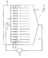
- Fig. 1 shows a water inlet 1, which branches via a manifold 2 to a plurality of water channels 3.
- the objects mentioned are located in a washroom 8 of a cleaning and disinfecting machine, in which cleaning liquid is conveyed by a circulating pump 9 from the sump 10 of the machine via a return channel 11 to the water inlet 1.
- the remaining parts of a commercial cleaning and disinfecting machine such as fresh water inlet, control device, metering device for cleaning and disinfecting agents, etc., are omitted for clarity.
- the flow constriction 4, the pressure sensor 5 and the coupling 6 can be formed as a coherent module 12 and connected to the respective water channel 3.
- the coupling 6 may be self-closing such that it is closed when not connected hollow body 7 and automatically opens by connecting a hollow body.
- each module 12 with an unillustrated shut-off valve.
- the coupling 6 can - as shown - be a so-called. Luer connection.
- the operation of the device is as follows: It is assumed that a hollow body is connected to each module 12 shown.
- liquid is supplied with an inlet pressure P 0 via the manifold 2 the individual water channels 3.
- This inlet pressure P 0 is substantially greater than the pressure with which the individual hollow body 7 are cleaned. It is for example in the order of 1 to 1.5 bar. If the flow path is substantially open, a pressure drop will occur at the respective flow constriction 4, so that a lower pressure P 1 is present at the flow-side outlet of the flow constriction 4, which is for example at 300 mbar.
- This pressure P 1 acts on the respective sensor 5.
- the sensor 5 is equipped with a memory function which stores whether the measured pressure P 1 has exceeded a predetermined value.
- This value can be, for example, 600 mbar and is significant for the fact that the respective hollow body is completely or partially blocked.
- the pressure sensor stores whether this increased value has been exceeded once and then emits a permanent signal, which is maintained even after falling below this increased pressure value again. This can be read after completion of the cleaning process to the individual pressure sensors, whether there the increased pressure value has occurred.
- the associated hollow body can then be sorted out, while the remaining hollow body considered to be properly cleaned.
- Fig. 2 shows a preferred embodiment of a module 12 with a flow restriction or nozzle 4, a pressure sensor 5 with memory function and a clutch 6.
- pressure sensors of the type used here can be implemented in a variety of ways, such as electromechanical sensors with electronic storage, however, the expensive and are sensitive to heat and humidity as well as need a power supply, via sensors with mechanical hold function ( Fig. 3 ) or magnetic holding function ( Fig. 4 ).
- sensors with mechanical hold function Fig. 3
- magnetic holding function Fig. 4
- sensors that uniquely limit the storage function and the function of a safety valve with respect to the maximum pressure that is applied to the hollow body.
- the design of the sensor should be as inexpensive as possible, robust against the effects of temperature and moisture as well as easily adaptable to different input and cleaning pressures P 0 and P 1 .
- the flow constriction 4 is designed as a threaded screw 13 which is screwed into a threaded sleeve 14 which is connected to the water channel 3, and thus projects into the interior of the water channel 13.
- a manually operable rotary handle 15 allows the screwing in and out of the screw 13.
- the pressure P 1 can be adapted quickly and flexibly to the respective requirements arising from the dimensioning of the individual lumens of the hollow bodies 7.
- a very simple embodiment of a pressure sensor 5 consists of a sleeve 16 connected to the water channel and a piston 17 slidingly slidable therein, the end face 18 of which is acted upon by the pressure P 1 in the water channel 3.
- a weight 19 is attached to the piston 17, whose diameter is greater than the diameter of the sleeve 16 and which loads the piston 17 with its own weight.
- the piston 17 and the weight 19 may be integrally formed.
- a disc 20 may be attached, which as Support for the weight 19 is used.
- the weight 19 is fixed by a flexible support 21, which may be, for example, a plastic thread, a metal chain or other, to the sleeve or the water channel 3 and secured against loss.
- the piston 17 and the weight 19 are pressed against the force of gravity along the sleeve 16 by the water channel 3. If the pressure reaches a predetermined limit, the piston 17 is completely pushed out of the sleeve 16 and the sleeve 16 thus acts as an opening of the water channel 13 and thus as a pressure relief valve. The piston 17 with weight 19 is secured by the holder 21 against loss.
- the seal between sleeve 16 and piston 17 is to be chosen so that a movement of the piston 17 is not inhibited, but still can escape only very small amounts of liquid.
- a very compact and simple pressure sensor can be realized, which preferably consists of stainless steel and can be designed for the pressures of interest here in the order of 100 mbar to 1 bar.
- the responsiveness of the sensor is given by the total weight of the weight 19 and the piston 17 and the end face 18.
- Fig. 3 shows an embodiment of a pressure sensor, which also has the sleeve 16, the piston 17 and the weight 19, wherein the weight optionally also by a spring 22 may be loaded.
- the weight is in this case accommodated in a housing 23 which has on its upper side a viewing window 24 made of flexible material.
- the weight has at its radial outer periphery a groove 25.
- In the housing at least one radially inwardly biased against the weight spring 26 is arranged, which has a latching nose 27. If the piston 17 and the weight 19 are raised so far that the locking lug 27 engages in the groove 25, this position of piston and weight remains stored, even if the pressure in the water channel 3 drops again.
- the piston 17 and the weight 19 are in their upper limit position, so the corresponding pressure value has been exceeded. Since the viewing window is flexible, the weight can be pushed back by hand, for example, back down towards the water channel 3 in its normal measuring position.
- the memory function is realized by magnets 28 and 29 which are mounted on the one hand on the piston and on the other hand on the housing 23.
Landscapes
- Health & Medical Sciences (AREA)
- Life Sciences & Earth Sciences (AREA)
- Surgery (AREA)
- Animal Behavior & Ethology (AREA)
- Engineering & Computer Science (AREA)
- Veterinary Medicine (AREA)
- Public Health (AREA)
- General Health & Medical Sciences (AREA)
- Heart & Thoracic Surgery (AREA)
- Biomedical Technology (AREA)
- Molecular Biology (AREA)
- Medical Informatics (AREA)
- Physics & Mathematics (AREA)
- Nuclear Medicine, Radiotherapy & Molecular Imaging (AREA)
- Pathology (AREA)
- Mechanical Engineering (AREA)
- Biophysics (AREA)
- Optics & Photonics (AREA)
- Radiology & Medical Imaging (AREA)
- Epidemiology (AREA)
- Chemical & Material Sciences (AREA)
- General Physics & Mathematics (AREA)
- Chemical Kinetics & Catalysis (AREA)
- General Chemical & Material Sciences (AREA)
- Oral & Maxillofacial Surgery (AREA)
- Infusion, Injection, And Reservoir Apparatuses (AREA)
- External Artificial Organs (AREA)
- Endoscopes (AREA)
- Measuring Volume Flow (AREA)
- Apparatus For Disinfection Or Sterilisation (AREA)
- Measuring Fluid Pressure (AREA)
Description
- Die Erfindung bezieht sich auf eine Vorrichtung zum Reinigen und/oder Desinfizieren von langgestreckten Hohlkörpern, insbesondere von medizinischen schläuchen und Kathetern.
- Die ältere, nicht vorveröffentlichte
EP 1 338 237 A2 schlägt für die Validierung der Reinigung mehrerer Kanäle von Endoskopen vor, jedem Kanal einen Flüssigkeitsbehälter mit einem vorbestimmten Volumen zuzuordnen und zu überprüfen, ob dieses Volumen innerhalb vorgegebener Zeit durch den Kanal geflossen ist. Die Flüssigkeitsbehälter sind über eine Strömungsverengung an eine Druckluftquelle abgeschlossen. Ein an den Druckluftkreis angeschlossenen Drucksensor misst den Luftdruck und stellt bei stärkerem Druckabfall fest, dass die Flüssigkeitsbehälter leer sind. - Die
EP 0 709 056 A1 , der für den Gegenstand des Anspruchs 1 als nächstliegender Stand der Technik angesehen wird, beschreibt ein Verfahren und eine Vorrichtung zum Reinigen und Desinfizieren von Endoskopen, mit mindestens einer an einem Wasserkanal angeschlossenen Kupplung zur Verbindung des Strömungsrichtung vor der Kupplung ein Drucksensor zum Erfassen des im Hohlkörper entstehenden Druckes angeordnet ist. - Die
EP 0 711 529 A1 beschreibt ein Verfahren zum Prüfen und Reinigen von Endoskopen, bei der jeder Fluidkanal über einen Verteiler mit Ventilen an eine Fluidquelle anschließbar ist. Mittels eines Durchflußprüfgerätes wird die Durchlässigkeit der Kanäle einzeln oder in Gruppen nacheinander geprüft, indem den Kanälen Fluid aus der Fluidquelle zugeführt wird. Zur Überprüfung der Durchlässigkeit wird überprüft, ob ein bestimmtes Fluidvolumen in einer bestimmten Zeiteinheit durch den jeweiligen Kanal geleitet wird. Die Messung der Durchflußmenge pro Zeiteinheit erfolgt dadurch, daß das Fluid unter Druck durch den Kanal gepresst wird und der zeitliche Verlauf des Druckabfalles ausgewertet wird, woraus sich das durchströmte Volumen bestimmen läßt. Aufgrund des ermittelten Volumens pro Zeiteinheit soll dann das spezifische Endoskop identifiziert werden, indem der gemessene Wert mit gerätespezifischen Werten verglichen wird. - Die
DE 296 20 011 U1 schlägt vor, zum Reinigen mehrerer Katheter oder Schläuche an einem Wasserkanal mehrere Aufsteckdüsen anzubringen, die eine unlösbar mit ihr verbundene Befestigungseinrichtung aufweisen, die die Außenseite des zu reinigenden Gegenstandes form- oder kraftschlüssig halten. Diese Aufsteckdüsen dienen als Kupplung zur Verbindung des Schlauches mit dem Wasserkanal. - Zur Validierung des Reinigungs- und/oder Desinfektionsergebnisses von langen dünnen Hohlkörpern wird die Forderung gestellt, festzustellen, ob tatsächlich die gewünschte Menge Flüssigkeit durch den Hohlkörper geflossen ist.
- Die
DE 36 01 395 A1 beschreibt eine Vorrichtung zur Anzeige anormaler Betriebszustände bei einer Endoskopwaschmaschine. - Mit einer Vielzahl von Sensoren werden bestimmte Parameter, wie z.B. Pegelstände von Reinigungsflüssigkeit, gemessen bzw. überwacht und daraus ermittelt, ob eine Störung oder ein anormaler Betriebszustand vorliegen.
- Aufgabe der Erfindung ist es daher, die bekannte Vorrichtung dahingehend zu verbessern, daß mit vereinfachtem technischem Aufwand überprüft werden kann, ob ein Hohlkörper gereinigt wurde.
- Diese Aufgabe wird durch die im Patentanspruch 1 angegebenen Merkmale gelöst. Vorteilhafte Ausgestaltungen und Weiterbildungen der Erfindung sind den Unteransprüchen zu entnehmen.
- Das Grundprinzip der Erfindung besteht darin, im Wasserkanal vor der Kupplung zum Hohlkörper eine Strömungsverengung und einen Drucksensor mit Speicherfunktion anzuordnen, wobei der Drucksensor aus einer an den Wasserkanal angeschlossenen Hülse und einem in der Hülse verschieblichen Kolben besteht. Durch die Strömungsverengung wird der Speisedruck der Reinigungsflüssigkeit zum Wasserkanal bei einwandfreiem Durchfluß durch den Hohlkörper herabgesetzt. Ist der Hohlkörper dagegen ganz oder teilweise verstopft, so entsteht ein demgegenüber erhöhter Staudruck, der vom Drucksensor erfaßt und gespeichert wird. Nach Beendigung des Reinigungsvorganges kann an diesem gespeicherten Druckwert erkannt werden, daß der entsprechende Hohlkörper nicht einwandfrei gereinigt wurde.
- Der Drucksensor muß nach einer vorteilhaften Weiterbildung der Erfindung lediglich messen und speichern, ob der gemessene Druck einen vorbestimmten Wert überschritten hat. Der Drucksensor kann damit quasi als Schalter ausgeführt sein, der nur die zwei Zustände "vorgegebener Druck überschritten" oder "vorgegebener Druck nicht überschritten" misst und speichert.
- Nach einer besonders vorteilhaften Ausgestaltung der Erfindung wird der Kolben durch sein Eigengewicht in Richtung zum Wasserkanal gedrückt wird. Ist der vorbestimmte Druck überschritten, so wird dieser Kolben vollständig aus der Hülse herausgedrückt. Die Speicherfunktion liegt dann darin, daß der Kolben nicht mehr in der Hülse ist. Ein wesentlicher Vorteil liegt noch darin, daß dann die an den Wasserkanal angeschlossene Hülse als Überdruckventil wirkt, womit erreicht wird, daß der Druck in einem ganz oder teilweise verstopften Hohlkörper einen bestimmten Grenzwert nicht überschreitet. Der Kolben ist durch ein elastisches Halteorgan unverlierbar an dem Wasserkanal oder der Hülse befestigt. Es kann sich hierbei um eine einfache seilartige Befestigung handeln.
- Nach einer anderen Variante kann der Kolben auch durch eine Feder in Richtung auf den Wasserkanal vorgespannt sein, wobei dann Einrichtungen vorgesehen sind, um den Kolben in einer vorbestimmten oberen Stellung zu halten, auch wenn der Druck später wieder absinkt, wodurch die Speicherfunktion erhalten wird. Diese Einrichtung kann beispielsweise darin bestehen, daß an dem Kolben eine Rastnut vorhanden ist und an der Hülse eine Feder angebracht ist, die bei Erreichen einer vorbestimmten Grenzstellung in die Rastnut einrastet. Eine andere Möglichkeit besteht darin, am Kolben und der Hülse jeweils Magneten anzubringen, die den Kolben ebenfalls in einer vorbestimmten Stellung halten, sofern diese durch den gemessenen Druck erreicht wurde. Nach Abschluß des Reinigungsvorganges kann man dann ebenfalls sehr einfach erkennen, ob einer der Kolben in der oberen Grenzstellung gehalten ist, was signalisiert, daß das Reinigungsergebnis nicht zufriedenstellend war.
- Nach einer vorteilhaften Weiterbildung der Erfindung ist die Strömungsverengung, die in Strömungsrichtung vor dem Drucksensor liegt, als einstellbare Düse ausgebildet, die im einfachsten Falle aus einer in den Wasserkanal einschraubbaren Schraube besteht. Hiermit kann eine Anpassung an den Speisedruck zum Reinigungskanal und an den gewünschten Druck der durch den Hohlkörper strömenden Flüssigkeit vorgenommen werden. Auch kann der Ansprechdruck des Sensors eingestellt werden, im einfachsten Fall des durch sein Eigengewicht belasteten Kolbens durch das Gewicht des Kolbens, bei Verwendung einer Feder durch Justieren der Feder oder Auswechseln der Feder durch eine Feder mit anderer Federhärte.
- Im folgenden wird die Erfindung anhand von Ausführungsbeispielen im Zusammenhang mit der Zeichnung ausführlicher erläutert. Es zeigt:
- Fig. 1
- eine Prinzipskizze einer Vorrichtung nach der Erfindung;
- Fig. 2
- ein bevorzugtes Ausführungsbeispiel einer bei der Erfindung verwendeten Strömungsverengung und eines Drucksensors mit Speicherfünktion;
- Fig. 3
- ein zweites Ausführungsbeispiel eines Drucksensors mit Speicherfunktion; und
- Fig. 4
- ein drittes Ausführungsbeispiel eines Drucksensors mit Speicherfunktion.
-
Fig. 1 zeigt einen Wasserzulauf 1, der über einen Rohrverteiler 2 zu einer Vielzahl von Wasserkanälen 3 verzweigt. In jedem Wasserkanal 3 ist eine einstellbare Strömungsverengung 4, ein Drucksensor 5 mit Speicherfunktion und eine Kupplung 6 vorhanden, wobei über jede Kupplung ein zu reinigender Hohlkörper 7, insbesondere ein medizinischer Schlauch oder ein Katheter anschließbar ist. Die genannten Gegenstände befinden sich in einem Waschraum 8 einer Reinigungs- und Desinfektionsmaschine, bei welcher Reinigungsflüssigkeit durch eine Umwälzpumpe 9 vom Sumpf 10 der Maschine über einen Rückführkanal 11 zum Wasserzulauf 1 gefördert wird. Die übrigen Teile einer handelsüblichen Reinigungs- und Desinfektionsmaschine, wie z.B. Frischwasserzulauf, Steuereinrichtung, Dosiereinrichtung für Reinigungs- und Desinfektionsmittel etc., sind der Übersichtlichkeit halber fortgelassen. - Die Strömungsverengung 4, der Drucksensor 5 und die Kupplung 6 können als ein zusammenhängendes Modul 12 ausgebildet und an den jeweiligen Wasserkanal 3 angeschlossen sein. Die Kupplung 6 kann selbstschließend ausgebildet sein derart, daß sie bei nicht angeschlossenem Hohlkörper 7 geschlossen ist und durch Anschließen eines Hohlkörpers automatisch öffnet. Es ist aber auch möglich, jedem Modul 12 noch ein nicht dargestelltes Absperrventil zuzuordnen. Die Kupplung 6 kann - wie dargestellt - ein sog. Luer-Anschluß sein.
- Die Arbeitsweise der Vorrichtung ist wie folgt:
Es wird davon ausgegangen, daß an alle dargestellten Module 12 je ein Hohlkörper angeschlossen ist. Durch die Umwälzpumpe 9 wird Flüssigkeit mit einem Eingangsdruck P0 über den Rohrverteiler 2 den einzelnen Wasserkanälen 3 zugeführt. Dieser Eingangsdruck P0 ist wesentlich größer als der Druck, mit dem die einzelnen Hohlkörper 7 gereinigt werden. Er liegt beispielsweise in der Größenordnung von 1 bis 1,5 bar. Ist der Strömungsweg im wesentlichen offen, so wird an der jeweiligen Strömungsverengung 4 ein Druckabfall auftreten, so daß am strömungsseitigen Ausgang der Strömungsverengung 4 ein geringerer Druck P1 ansteht, der beispielsweise bei 300 mbar liegt. Dieser Druck P1 beaufschlagt den jeweiligen Sensor 5. Der Sensor 5 ist mit einer Speicherfunktion ausgestattet, die speichert, ob der gemessene Druck P1 einen vorbestimmten Wert überschritten hat. Dieser Wert kann beispielsweise bei 600 mbar liegen und ist signifikant dafür, daß der jeweilige Hohlkörper ganz oder teilweise verstopft ist. Der Drucksensor speichert, ob dieser erhöhte Wert einmal überschritten wurde und gibt dann ein dauerhaftes Signal ab, das auch nach erneutem Unterschreiten dieses erhöhten Druckwertes erhalten bleibt. Damit kann nach Beendigung des Reinigungsvorganges an den einzelnen Drucksensoren abgelesen werden, ob dort der erhöhte Druckwert aufgetreten ist. Die zugeordneten Hohlkörper können dann aussortiert werden, während die übrigen Hohlkörper als einwandfrei gereinigt gelten. -
Fig. 2 zeigt ein bevorzugtes Ausführungsbeispiel eines Modules 12 mit einer Strömungsverengung bzw. Düse 4, einem Drucksensor 5 mit Speicherfunktion und einer Kupplung 6. Generell können Drucksensoren der hier verwendeten Art auf die verschiedenste Weise realisiert werden, beispielsweise elektromechanische Sensoren mit elektronischer Speicherung, die allerdings teuer und empfindlich gegen Hitze und Feuchtigkeit sind sowie eine Stromversorgung benötigen, über Sensoren mit mechanischer Haltefunktion (Fig. 3 ) oder magnetischer Haltefunktion (Fig. 4 ). Von besonderem Interesse sind hierbei Sensoren, die die Speicherfunktion sowie die Funktion eines Sicherheitsventils bezüglich des maximalen Drucks, der auf den Hohlkörper gegeben wird, eindeutig begrenzt, verknüpfen. Außerdem sollte die Ausführung des Sensors möglichst preiswert, robust gegen Temperatur- und Feuchtigkeitseinwirkung sowie einfach an verschiedene Eingangs- und Reinigungsdrücke P0 und P1 adaptierbar sein. - Ein diese Forderung erfüllendes Modul zeigt
Fig. 2 . Die Strömungsverengung 4 ist als Gewindeschraube 13 ausgeführt, die in eine Gewindehülse 14, die an den Wasserkanal 3 angeschlossen ist, einschraubbar ist und damit in das Innere des Wasserkanals 13 hineinragt. Ein von Hand betätigbarer Drehgriff 15 erlaubt das Ein- und Ausdrehen der Schraube 13. Hiermit kann der Druck P1 schnell und flexibel den jeweiligen Anforderungen, die sich aus der Dimensionierung der einzelnen Lumen der Hohlkörper 7 ergeben, angepaßt werden. - Eine sehr einfache Ausführung eines Drucksensors 5 besteht aus einer an den Wasserkanal angeschlossenen Hülse 16 und einem darin gleitend verschieblichen Kolben 17, dessen Stirnfläche 18 mit dem Druck P1 im Wasserkanal 3 beaufschlagt wird. Außerhalb der Hülse 16 ist an den Kolben 17 ein Gewicht 19 angebracht, dessen Durchmesser größer ist als der Durchmesser der Hülse 16 und das den Kolben 17 mit seinem Eigengewicht belastet. Selbstverständlich können der Kolben 17 und das Gewicht 19 einstückig ausgebildet sein. An der Hülse 16 kann eine Scheibe 20 angebracht sein, die als Auflage für das Gewicht 19 dient. Das Gewicht 19 ist durch eine flexible Halterung 21, die beispielsweise ein Kunststoffaden, eine Metallkette oder sonstiges sein kann, an der Hülse oder dem Wasserkanal 3 befestigt und so gegen Verlieren gesichert.
- Steigt der Druck P1 im Wasserkanal an, so werden der Kolben 17 und das Gewicht 19 entgegen der Schwerkraft längs der Hülse 16 vom Wasserkanal 3 fortgedrückt. Erreicht der Druck einen vorbestimmten Grenzwert, so wird der Kolben 17 vollständig aus der Hülse 16 herausgedrückt und die Hülse 16 wirkt damit als Öffnung des Wasserkanals 13 und damit als Überdruckventil. Der Kolben 17 mit Gewicht 19 wird durch die Halterung 21 gegen Verlust gesichert.
- Die Speicherfunktion wird also dadurch erfüllt, daß der Kolben 17 mit Gewicht 19 aus der Hülse 16 herausgefallen ist. Dies ist einer Bedienperson sofort ersichtlich und ist so zu interpretieren, daß das Lumen des entsprechenden Hohlkörpers ganz oder teilweise verstopft war, auf alle Fälle also nicht ordnungsgemäß gereinigt wurde.
- Die Abdichtung zwischen Hülse 16 und Kolben 17 ist so zu wählen, daß eine Bewegung des Kolbens 17 nicht gehemmt wird, trotzdem aber nur sehr geringe Mengen an Flüssigkeit entweichen können. Durch Dimensionierung der Durchmesser von Hülse 16 und Kolben 17 sowie des Gewichtes 19 kann ein sehr kompakter und einfacher Drucksensor realisiert werden, der vorzugsweise aus Edelstahl besteht und für die hier interessierenden Drücke in der Größenordnung von 100 mbar bis 1 bar ausgelegt werden kann. Die Ansprechempfindlichkeit des Sensors ist durch das Gesamtgewicht des Gewichtes 19 und des Kolbens 17 und die Stirnfläche 18 gegeben.
-
Fig. 3 zeigt ein Ausführungsbeispiel eines Drucksensors, der ebenfalls die Hülse 16, den Kolben 17 und das Gewicht 19 aufweist, wobei das Gewicht optional auch noch durch eine Feder 22 belastet sein kann. Das Gewicht ist hierbei in einem Gehäuse 23 untergebracht, das an seiner Oberseite ein Sichtfenster 24 aus flexiblem Material aufweist. Das Gewicht hat an seinem radialen Außenumfang eine Nut 25. Im Gehäuse ist mindestens eine radial nach innen gegen das Gewicht vorgespannte Feder 26 angeordnet, die eine Rastnase 27 aufweist. Sind der Kolben 17 und das Gewicht 19 so weit angehoben, daß die Rastnase 27 in die Nut 25 einrastet, so bleibt diese Position von Kolben und Gewicht gespeichert, auch wenn der Druck im Wasserkanal 3 wieder abfällt. Am Sichtfenster 24 ist dann zu erkennen, daß der Kolben 17 und das Gewicht 19 in ihrer oberen Grenzlage sind, also der entsprechende Druckwert überschritten wurde. Da das Sichtfenster flexibel ist, kann das Gewicht z.B. von Hand wieder nach unten in Richtung zum Wasserkanal 3 in seine normale Meßstellung zurückgedrückt werden. - Im Ausführungsbeispiel der
Fig. 4 wird die Speicherfunktion durch Magnete 28 und 29 realisiert, die einerseits am Kolben und andererseits am Gehäuse 23 angebracht sind. Sobald der Kolben 17 so weit hochgedrückt ist, daß die Magnete 28 und 29 in etwa fluchten, hält die Magnetkraft den Kolben in der erreichten Stellung, auch wenn der Druck in dem Wasserkanal 3 wieder absinkt. Die Magnetkraft ist dabei so stark, daß auch das Eigengewicht des Kolbens 17 und ggf. auch die Kraft der Feder 22 nicht ausreichen, diese Kraft zu überwinden. Auch hier ist die Oberseite des Gehäuses 22 mit einem durchsichtigen, flexiblen Fenster 24 versehen, durch welches einerseits die Position des Kolbens 17 abgelesen werden kann und andererseits der Kolben auch wieder aus der "Speicherstellung" gelöst und in die Arbeitsstellung gedrückt werden kann.
Claims (9)
- Vorrichtung zum Reinigen und/oder Desinfizieren von Hohlkörpern (7), insbesondere von medizinischen Schläuchen und Kathetern, mit mindestens einer an einen Wasserkanal (3) angeschlossenen Kupplung (6) zur Verbindung des Wasserkanales (3) mit dem Hohlkörper (7), wobei in Strömungsrichtung vor der Kupplung (6) eine an den Wasserkanal (3) angeschlossene Strömungsverengung (4) und ein Drucksensor (5) zum Erfassen und Speichern von in dem Hohlkörper (7) entstehenden Druck angeordnet sind, und der Drucksensor (5) eine an den Wasserkanal (3) angeschlossene Hülse (16) und einen in der Hülse (16) verschieblichen Kolben (17) aufweist.
- Vorrichtung nach Anspruch 1, dadurch gekennzeichnet, daß der Drucksensor (5) so ausgebildet ist, daß er dauerhaft ablesbar speichert, ob der erfaßte Druck einen vorbestimmten Wert überschritten hat.
- Vorrichtung nach Anspruch 2, dadurch gekennzeichnet,
daß der Kolben (17) durch sein Eigengewicht und ggf. ein zusätzliches Gewicht (19) in Richtung zum Wasserkanal (3) gedrückt wird und bei dem vorbestimmten Druck vollständig aus der Hülse (16) herausgedrückt wird. - Vorrichtung nach Anspruch 3, dadurch gekennzeichnet,
daß der Kolben mit einer flexiblen Halterung (21) an dem Wasserkanal (3) oder der Hülse (16) befestigt ist. - Vorrichtung nach Anspruch 4, dadurch gekennzeichnet,
daß der Kolben (16) durch eine Feder (22) in Richtung zum Wasserkanal (3) gedrückt wird. - Vorrichtung nach einem der Ansprüche 2, 4 oder 5, dadurch gekennzeichnet,
daß am Kolben (17, 19) eine Rastnut (25) angebracht ist und an einem Gehäuse (23) eine Feder (26), die bei Erreichen einer vorbestimmten Grenzstellung in die Rastnut (25) einrastet. - Vorrichtung nach einem der Ansprüche 2, 4 oder 5, dadurch gekennzeichnet,
daß an dem Kolben mindestens ein Magnet (27) und an einem Gehäuse (23), in welchem der Kolben (17) verschieblich geführt ist, ein Gegenmagnet (28) angebracht ist. - Vorrichtung nach einem der Ansprüche 1 bis 7, dadurch gekennzeichnet,
daß die Strömungsverengung (4) einstellbar ist. - Vorrichtung nach Anspruch 8, dadurch gekennzeichnet,
daß die Strömungsverengung (4) eine in den Wasserkanal (3) einschraubbare Schraube (13) ist.
Priority Applications (1)
| Application Number | Priority Date | Filing Date | Title |
|---|---|---|---|
| SI200431605T SI1477238T1 (sl) | 2003-05-16 | 2004-03-27 | Naprava za čiščenje in/ali dezinficiranje podolgovatih votlih teles, še zlasti medicinskih gibkih cevi in katetrov |
Applications Claiming Priority (2)
| Application Number | Priority Date | Filing Date | Title |
|---|---|---|---|
| DE10321991 | 2003-05-16 | ||
| DE10321991A DE10321991B3 (de) | 2003-05-16 | 2003-05-16 | Vorrichtung zum Reinigen und/oder Desinfizieren von langgestreckten Hohlkörpern, insbesondere von medizinischen Schläuchen und Kathetern |
Publications (3)
| Publication Number | Publication Date |
|---|---|
| EP1477238A2 EP1477238A2 (de) | 2004-11-17 |
| EP1477238A3 EP1477238A3 (de) | 2005-11-30 |
| EP1477238B1 true EP1477238B1 (de) | 2010-11-17 |
Family
ID=32115635
Family Applications (1)
| Application Number | Title | Priority Date | Filing Date |
|---|---|---|---|
| EP04007482A Expired - Lifetime EP1477238B1 (de) | 2003-05-16 | 2004-03-27 | Vorrichtung zum Reinigen und/oder Desinfizieren von langgestreckten Hohlkörpern, insbesondere von medizinischen Schläuchen und Kathedern |
Country Status (5)
| Country | Link |
|---|---|
| EP (1) | EP1477238B1 (de) |
| AT (1) | ATE488308T1 (de) |
| DE (2) | DE10321991B3 (de) |
| DK (1) | DK1477238T3 (de) |
| SI (1) | SI1477238T1 (de) |
Cited By (1)
| Publication number | Priority date | Publication date | Assignee | Title |
|---|---|---|---|---|
| DE102013226637A1 (de) | 2013-12-19 | 2015-06-25 | Meiko Maschinenbau Gmbh & Co. Kg | Reinigungsvorrichtung und Verfahren zur Reinigung von Reinigungsgut |
Families Citing this family (13)
| Publication number | Priority date | Publication date | Assignee | Title |
|---|---|---|---|---|
| DE102004040734B3 (de) * | 2004-08-20 | 2005-09-15 | Bht Hygienetechnik Gmbh | Vorrichtung zum Reinigen und/oder Desinfizieren von langgestreckten Hohlkörpern, insbesondere von medizinischen Schläuchen und Kathetern |
| US7901349B2 (en) | 2005-11-02 | 2011-03-08 | Minntech Corporation | Endoscope reprocessor connectivity apparatus and method |
| DE102006031918A1 (de) * | 2006-07-10 | 2008-01-17 | Christian Kluge | Transportable Vorrichtung zur Beseitigung von Mikroorganismen |
| DE102009036564A1 (de) * | 2009-08-10 | 2011-02-17 | Olympus Winter & Ibe Gmbh | Verbindungsvorrichtung zur Verwendung in einem Reinigungsraum in einer Reinigungsvorrichtung zur Reinigung von chirurgischen Instrumenten |
| US8673212B2 (en) * | 2010-05-28 | 2014-03-18 | Steris Corporation | Apparatus to decontaminate equipment containing internal channels |
| DE102011082776A1 (de) * | 2011-09-15 | 2013-03-21 | Olympus Winter & Ibe Gmbh | Verfahren und Vorrichtung zum Spülen von Endoskopkanälen |
| DE102012020934B4 (de) | 2012-10-25 | 2014-08-21 | SciCan GmbH | Verfahren zum Reinigen und Desinfizieren von Endoskopen |
| DE102013204038B4 (de) | 2013-03-08 | 2016-10-27 | Melag Medizintechnik Ohg | Trägersystem zur Aufnahme von medizinischen oder zahnmedizinischen Instrumenten und Verfahren zur Bestimmung einer Flüssigkeitsdurchlässigkeit eines Filters eines solchen Trägersystems |
| CN105499223A (zh) * | 2015-12-30 | 2016-04-20 | 天津市鑫思汇智科技发展有限公司 | 一种医疗器械循环灌流清洗装置 |
| CN110976410A (zh) * | 2019-11-19 | 2020-04-10 | 老肯医疗科技股份有限公司 | 一种用于清洗管腔器械的清洗管路系统及其使用方法 |
| CN111804678A (zh) * | 2020-07-17 | 2020-10-23 | 提技贸易(上海)有限公司 | 一种中央排管自动清扫系统及控制方法 |
| EP4344609A1 (de) | 2022-09-30 | 2024-04-03 | comprex Medical GmbH | Verfahren und vorrichtung zur reinigung von medizinischen instrumenten mittels modulierender druckgasimpulse |
| CN115655589B (zh) * | 2022-12-05 | 2023-03-14 | 常州瑞迈医疗科技有限公司 | 一种管状医疗器械用密封性测试装置 |
Family Cites Families (5)
| Publication number | Priority date | Publication date | Assignee | Title |
|---|---|---|---|---|
| JPS61257624A (ja) * | 1985-01-18 | 1986-11-15 | オリンパス光学工業株式会社 | 内視鏡洗浄機の異常表示装置 |
| NL9401788A (nl) | 1994-10-27 | 1996-06-03 | Fujinon Medical Holland B V | Werkwijze en inrichting voor het reinigen en desinfecteren van endoscopen. |
| DE4440363C2 (de) * | 1994-11-11 | 1997-10-02 | Netzsch Newamatic Gmbh | Verfahren zum Prüfen und Reinigen von Instrumenten für die minimal invasive Chirurgie oder minimal invasive Untersuchung von Körperhöhlen |
| DE29620011U1 (de) * | 1996-11-18 | 1997-01-09 | Biermaier Hans | Vorrichtung zur Innenreinigung hohler medizinischer Gegenstände, insbesondere von Kathetern oder Schläuchen |
| DE10208035B4 (de) | 2002-02-26 | 2005-10-06 | Bht Hygiene Technik Gmbh | Vorrichtung zum Überprüfen der Durchgängigkeit von Endoskopkanälen |
-
2003
- 2003-05-16 DE DE10321991A patent/DE10321991B3/de not_active Expired - Fee Related
-
2004
- 2004-03-27 DK DK04007482.5T patent/DK1477238T3/da active
- 2004-03-27 DE DE502004011888T patent/DE502004011888D1/de not_active Expired - Lifetime
- 2004-03-27 EP EP04007482A patent/EP1477238B1/de not_active Expired - Lifetime
- 2004-03-27 SI SI200431605T patent/SI1477238T1/sl unknown
- 2004-03-27 AT AT04007482T patent/ATE488308T1/de active
Cited By (3)
| Publication number | Priority date | Publication date | Assignee | Title |
|---|---|---|---|---|
| DE102013226637A1 (de) | 2013-12-19 | 2015-06-25 | Meiko Maschinenbau Gmbh & Co. Kg | Reinigungsvorrichtung und Verfahren zur Reinigung von Reinigungsgut |
| WO2015091750A1 (de) | 2013-12-19 | 2015-06-25 | Meiko Maschinenbau Gmbh & Co. Kg | Reinigungsvorrichtung und verfahren zur reinigung von reinigungsgut |
| US10561294B2 (en) | 2013-12-19 | 2020-02-18 | Meiko Maschinenbau Gmbh & Co., Kg | Cleaning appliance and method for cleaning articles to be cleaned |
Also Published As
| Publication number | Publication date |
|---|---|
| ATE488308T1 (de) | 2010-12-15 |
| DK1477238T3 (da) | 2011-03-07 |
| SI1477238T1 (sl) | 2011-06-30 |
| EP1477238A3 (de) | 2005-11-30 |
| DE10321991B3 (de) | 2004-05-19 |
| DE502004011888D1 (de) | 2010-12-30 |
| EP1477238A2 (de) | 2004-11-17 |
Similar Documents
| Publication | Publication Date | Title |
|---|---|---|
| EP1477238B1 (de) | Vorrichtung zum Reinigen und/oder Desinfizieren von langgestreckten Hohlkörpern, insbesondere von medizinischen Schläuchen und Kathedern | |
| EP1749549B1 (de) | Liquor-Drainagesystem | |
| EP2020198B1 (de) | Verfahren und Vorrichtung zum Fördern von Lebensmitteln | |
| EP2981306B1 (de) | Vorrichtung mit einem durchflusskanal | |
| EP2617286B1 (de) | Landwirtschaftliche Feldspritze | |
| DE3706338A1 (de) | Membranpumpvorrichtung | |
| DE2754809A1 (de) | Vorrichtung zur periodischen spuelung von koerperhoehlen, insbesondere der bauchhoehle | |
| EP1950281B1 (de) | Messeinrichtung zur Bestimmung der Aktivität eines Fermentationsprozesses | |
| DE102014211961A1 (de) | Reinigungs- und/oder Desinfiziereinrichtung | |
| EP1960017B1 (de) | Verfahren zum freiblasen eines benetzten hydrophobfilters und vorrichtung zur durchführung des verfahrens | |
| EP1593345B1 (de) | Vorrichtung zur automatischen Überwachung des Flusses einer Flüssigkeit, insbesondere Urin | |
| DE3440848C2 (de) | ||
| EP0143294B1 (de) | Vorrichtung zum dosierbaren Zugeben eines Stoffes zu einem Lösungs- oder Verdünnungsmittel | |
| DE10208035B4 (de) | Vorrichtung zum Überprüfen der Durchgängigkeit von Endoskopkanälen | |
| EP1627693B1 (de) | Vorrichtung zum Reinigen und/oder Desinfizieren von langgestreckten Hohlkörpern, insbesondere von medizinischen Schläuchen und Kathetern | |
| DE3041593A1 (de) | Automatische sprueheinrichtung | |
| WO1998013074A1 (de) | Dosiervorrichtung zur zugabe von entkeimungs- oder desinfektionsmittel in eine wassergespeiste versorgungseinrichtung sowie deren verwendung | |
| DE102018106790A1 (de) | Container sowie Verfahren zu dessen Betrieb | |
| DE69927652T2 (de) | Dosiervorrichtung für nicht-gasförmiges fliessfähiges Material | |
| DE102014103071A1 (de) | Sterilisationsapparat | |
| DE102020202951A1 (de) | Dosiervorrichtung und Verfahren zum Betreiben einer Dosiervorrichtung | |
| EP3449804B1 (de) | Verfahren und vorrichtung zur gleichzeitigen adapteranschlussüberprüfung und zur durchgängigkeitsüberprüfung von endoskopkanälen | |
| WO2014086554A2 (de) | Verfahren und vorrichtung zur stellungsanzeige von hydraulisch betätigten armaturen | |
| DE102013204038B4 (de) | Trägersystem zur Aufnahme von medizinischen oder zahnmedizinischen Instrumenten und Verfahren zur Bestimmung einer Flüssigkeitsdurchlässigkeit eines Filters eines solchen Trägersystems | |
| EP3221195B1 (de) | Druckluftsystem mit hygroskopischem sensor |
Legal Events
| Date | Code | Title | Description |
|---|---|---|---|
| PUAI | Public reference made under article 153(3) epc to a published international application that has entered the european phase |
Free format text: ORIGINAL CODE: 0009012 |
|
| AK | Designated contracting states |
Kind code of ref document: A2 Designated state(s): AT BE BG CH CY CZ DE DK EE ES FI FR GB GR HU IE IT LI LU MC NL PL PT RO SE SI SK TR |
|
| AX | Request for extension of the european patent |
Extension state: AL LT LV MK |
|
| PUAL | Search report despatched |
Free format text: ORIGINAL CODE: 0009013 |
|
| AK | Designated contracting states |
Kind code of ref document: A3 Designated state(s): AT BE BG CH CY CZ DE DK EE ES FI FR GB GR HU IE IT LI LU MC NL PL PT RO SE SI SK TR |
|
| AX | Request for extension of the european patent |
Extension state: AL LT LV MK |
|
| 17P | Request for examination filed |
Effective date: 20060329 |
|
| AKX | Designation fees paid |
Designated state(s): AT BE BG CH CY CZ DE DK EE ES FI FR GB GR HU IE IT LI LU MC NL PL PT RO SE SI SK TR |
|
| 17Q | First examination report despatched |
Effective date: 20070111 |
|
| GRAP | Despatch of communication of intention to grant a patent |
Free format text: ORIGINAL CODE: EPIDOSNIGR1 |
|
| GRAJ | Information related to disapproval of communication of intention to grant by the applicant or resumption of examination proceedings by the epo deleted |
Free format text: ORIGINAL CODE: EPIDOSDIGR1 |
|
| GRAP | Despatch of communication of intention to grant a patent |
Free format text: ORIGINAL CODE: EPIDOSNIGR1 |
|
| GRAC | Information related to communication of intention to grant a patent modified |
Free format text: ORIGINAL CODE: EPIDOSCIGR1 |
|
| GRAJ | Information related to disapproval of communication of intention to grant by the applicant or resumption of examination proceedings by the epo deleted |
Free format text: ORIGINAL CODE: EPIDOSDIGR1 |
|
| RTI1 | Title (correction) |
Free format text: APPARATUS FOR CLEANING AND/OR DESINFECTING ELONGATED HOLLOW BODIES, IN PARTICULAR MEDICAL TUBES AND CATHETERS |
|
| GRAP | Despatch of communication of intention to grant a patent |
Free format text: ORIGINAL CODE: EPIDOSNIGR1 |
|
| GRAS | Grant fee paid |
Free format text: ORIGINAL CODE: EPIDOSNIGR3 |
|
| GRAA | (expected) grant |
Free format text: ORIGINAL CODE: 0009210 |
|
| AK | Designated contracting states |
Kind code of ref document: B1 Designated state(s): AT BE BG CH CY CZ DE DK EE ES FI FR GB GR HU IE IT LI LU MC NL PL PT RO SE SI SK TR |
|
| REG | Reference to a national code |
Ref country code: GB Ref legal event code: FG4D Free format text: NOT ENGLISH |
|
| REG | Reference to a national code |
Ref country code: CH Ref legal event code: EP |
|
| REG | Reference to a national code |
Ref country code: IE Ref legal event code: FG4D |
|
| REF | Corresponds to: |
Ref document number: 502004011888 Country of ref document: DE Date of ref document: 20101230 Kind code of ref document: P |
|
| REG | Reference to a national code |
Ref country code: DK Ref legal event code: T3 |
|
| REG | Reference to a national code |
Ref country code: NL Ref legal event code: VDEP Effective date: 20101117 |
|
| PG25 | Lapsed in a contracting state [announced via postgrant information from national office to epo] |
Ref country code: PT Free format text: LAPSE BECAUSE OF FAILURE TO SUBMIT A TRANSLATION OF THE DESCRIPTION OR TO PAY THE FEE WITHIN THE PRESCRIBED TIME-LIMIT Effective date: 20110317 Ref country code: NL Free format text: LAPSE BECAUSE OF FAILURE TO SUBMIT A TRANSLATION OF THE DESCRIPTION OR TO PAY THE FEE WITHIN THE PRESCRIBED TIME-LIMIT Effective date: 20101117 Ref country code: CY Free format text: LAPSE BECAUSE OF FAILURE TO SUBMIT A TRANSLATION OF THE DESCRIPTION OR TO PAY THE FEE WITHIN THE PRESCRIBED TIME-LIMIT Effective date: 20101117 Ref country code: SE Free format text: LAPSE BECAUSE OF FAILURE TO SUBMIT A TRANSLATION OF THE DESCRIPTION OR TO PAY THE FEE WITHIN THE PRESCRIBED TIME-LIMIT Effective date: 20101117 Ref country code: BG Free format text: LAPSE BECAUSE OF FAILURE TO SUBMIT A TRANSLATION OF THE DESCRIPTION OR TO PAY THE FEE WITHIN THE PRESCRIBED TIME-LIMIT Effective date: 20110217 Ref country code: FI Free format text: LAPSE BECAUSE OF FAILURE TO SUBMIT A TRANSLATION OF THE DESCRIPTION OR TO PAY THE FEE WITHIN THE PRESCRIBED TIME-LIMIT Effective date: 20101117 |
|
| REG | Reference to a national code |
Ref country code: IE Ref legal event code: FD4D |
|
| PG25 | Lapsed in a contracting state [announced via postgrant information from national office to epo] |
Ref country code: GR Free format text: LAPSE BECAUSE OF FAILURE TO SUBMIT A TRANSLATION OF THE DESCRIPTION OR TO PAY THE FEE WITHIN THE PRESCRIBED TIME-LIMIT Effective date: 20110218 |
|
| PG25 | Lapsed in a contracting state [announced via postgrant information from national office to epo] |
Ref country code: IE Free format text: LAPSE BECAUSE OF FAILURE TO SUBMIT A TRANSLATION OF THE DESCRIPTION OR TO PAY THE FEE WITHIN THE PRESCRIBED TIME-LIMIT Effective date: 20101117 Ref country code: ES Free format text: LAPSE BECAUSE OF FAILURE TO SUBMIT A TRANSLATION OF THE DESCRIPTION OR TO PAY THE FEE WITHIN THE PRESCRIBED TIME-LIMIT Effective date: 20110228 Ref country code: CZ Free format text: LAPSE BECAUSE OF FAILURE TO SUBMIT A TRANSLATION OF THE DESCRIPTION OR TO PAY THE FEE WITHIN THE PRESCRIBED TIME-LIMIT Effective date: 20101117 Ref country code: EE Free format text: LAPSE BECAUSE OF FAILURE TO SUBMIT A TRANSLATION OF THE DESCRIPTION OR TO PAY THE FEE WITHIN THE PRESCRIBED TIME-LIMIT Effective date: 20101117 |
|
| PG25 | Lapsed in a contracting state [announced via postgrant information from national office to epo] |
Ref country code: PL Free format text: LAPSE BECAUSE OF FAILURE TO SUBMIT A TRANSLATION OF THE DESCRIPTION OR TO PAY THE FEE WITHIN THE PRESCRIBED TIME-LIMIT Effective date: 20101117 Ref country code: RO Free format text: LAPSE BECAUSE OF FAILURE TO SUBMIT A TRANSLATION OF THE DESCRIPTION OR TO PAY THE FEE WITHIN THE PRESCRIBED TIME-LIMIT Effective date: 20101117 Ref country code: SK Free format text: LAPSE BECAUSE OF FAILURE TO SUBMIT A TRANSLATION OF THE DESCRIPTION OR TO PAY THE FEE WITHIN THE PRESCRIBED TIME-LIMIT Effective date: 20101117 |
|
| PLBE | No opposition filed within time limit |
Free format text: ORIGINAL CODE: 0009261 |
|
| STAA | Information on the status of an ep patent application or granted ep patent |
Free format text: STATUS: NO OPPOSITION FILED WITHIN TIME LIMIT |
|
| BERE | Be: lapsed |
Owner name: BHT HYGIENETECHNIK G.M.B.H. Effective date: 20110331 |
|
| 26N | No opposition filed |
Effective date: 20110818 |
|
| PG25 | Lapsed in a contracting state [announced via postgrant information from national office to epo] |
Ref country code: MC Free format text: LAPSE BECAUSE OF NON-PAYMENT OF DUE FEES Effective date: 20110331 |
|
| REG | Reference to a national code |
Ref country code: DE Ref legal event code: R097 Ref document number: 502004011888 Country of ref document: DE Effective date: 20110818 |
|
| PG25 | Lapsed in a contracting state [announced via postgrant information from national office to epo] |
Ref country code: IT Free format text: LAPSE BECAUSE OF FAILURE TO SUBMIT A TRANSLATION OF THE DESCRIPTION OR TO PAY THE FEE WITHIN THE PRESCRIBED TIME-LIMIT Effective date: 20101117 Ref country code: BE Free format text: LAPSE BECAUSE OF NON-PAYMENT OF DUE FEES Effective date: 20110331 |
|
| PGFP | Annual fee paid to national office [announced via postgrant information from national office to epo] |
Ref country code: CH Payment date: 20130319 Year of fee payment: 10 Ref country code: DK Payment date: 20130320 Year of fee payment: 10 Ref country code: GB Payment date: 20130318 Year of fee payment: 10 Ref country code: FR Payment date: 20130329 Year of fee payment: 10 |
|
| PG25 | Lapsed in a contracting state [announced via postgrant information from national office to epo] |
Ref country code: LU Free format text: LAPSE BECAUSE OF NON-PAYMENT OF DUE FEES Effective date: 20110327 |
|
| PGFP | Annual fee paid to national office [announced via postgrant information from national office to epo] |
Ref country code: SI Payment date: 20130320 Year of fee payment: 10 |
|
| PGFP | Annual fee paid to national office [announced via postgrant information from national office to epo] |
Ref country code: AT Payment date: 20130318 Year of fee payment: 10 |
|
| PG25 | Lapsed in a contracting state [announced via postgrant information from national office to epo] |
Ref country code: TR Free format text: LAPSE BECAUSE OF FAILURE TO SUBMIT A TRANSLATION OF THE DESCRIPTION OR TO PAY THE FEE WITHIN THE PRESCRIBED TIME-LIMIT Effective date: 20101117 |
|
| PG25 | Lapsed in a contracting state [announced via postgrant information from national office to epo] |
Ref country code: HU Free format text: LAPSE BECAUSE OF FAILURE TO SUBMIT A TRANSLATION OF THE DESCRIPTION OR TO PAY THE FEE WITHIN THE PRESCRIBED TIME-LIMIT Effective date: 20101117 |
|
| REG | Reference to a national code |
Ref country code: DK Ref legal event code: EBP Effective date: 20140331 |
|
| REG | Reference to a national code |
Ref country code: CH Ref legal event code: PL |
|
| REG | Reference to a national code |
Ref country code: AT Ref legal event code: MM01 Ref document number: 488308 Country of ref document: AT Kind code of ref document: T Effective date: 20140327 |
|
| GBPC | Gb: european patent ceased through non-payment of renewal fee |
Effective date: 20140327 |
|
| REG | Reference to a national code |
Ref country code: FR Ref legal event code: ST Effective date: 20141128 |
|
| REG | Reference to a national code |
Ref country code: SI Ref legal event code: KO00 Effective date: 20141104 |
|
| PG25 | Lapsed in a contracting state [announced via postgrant information from national office to epo] |
Ref country code: FR Free format text: LAPSE BECAUSE OF NON-PAYMENT OF DUE FEES Effective date: 20140331 Ref country code: CH Free format text: LAPSE BECAUSE OF NON-PAYMENT OF DUE FEES Effective date: 20140331 Ref country code: LI Free format text: LAPSE BECAUSE OF NON-PAYMENT OF DUE FEES Effective date: 20140331 Ref country code: GB Free format text: LAPSE BECAUSE OF NON-PAYMENT OF DUE FEES Effective date: 20140327 |
|
| PG25 | Lapsed in a contracting state [announced via postgrant information from national office to epo] |
Ref country code: SI Free format text: LAPSE BECAUSE OF NON-PAYMENT OF DUE FEES Effective date: 20140328 Ref country code: AT Free format text: LAPSE BECAUSE OF NON-PAYMENT OF DUE FEES Effective date: 20140327 |
|
| PG25 | Lapsed in a contracting state [announced via postgrant information from national office to epo] |
Ref country code: DK Free format text: LAPSE BECAUSE OF NON-PAYMENT OF DUE FEES Effective date: 20140331 |
|
| PGFP | Annual fee paid to national office [announced via postgrant information from national office to epo] |
Ref country code: DE Payment date: 20230329 Year of fee payment: 20 |
|
| P01 | Opt-out of the competence of the unified patent court (upc) registered |
Effective date: 20230513 |
|
| REG | Reference to a national code |
Ref country code: DE Ref legal event code: R071 Ref document number: 502004011888 Country of ref document: DE |