EP1477227A2 - Dispositif de régulation de pipettes - Google Patents
Dispositif de régulation de pipettes Download PDFInfo
- Publication number
- EP1477227A2 EP1477227A2 EP04252316A EP04252316A EP1477227A2 EP 1477227 A2 EP1477227 A2 EP 1477227A2 EP 04252316 A EP04252316 A EP 04252316A EP 04252316 A EP04252316 A EP 04252316A EP 1477227 A2 EP1477227 A2 EP 1477227A2
- Authority
- EP
- European Patent Office
- Prior art keywords
- pipette
- control arrangement
- connector
- arrangement according
- assembly
- Prior art date
- Legal status (The legal status is an assumption and is not a legal conclusion. Google has not performed a legal analysis and makes no representation as to the accuracy of the status listed.)
- Granted
Links
Images


Classifications
-
- B—PERFORMING OPERATIONS; TRANSPORTING
- B01—PHYSICAL OR CHEMICAL PROCESSES OR APPARATUS IN GENERAL
- B01L—CHEMICAL OR PHYSICAL LABORATORY APPARATUS FOR GENERAL USE
- B01L3/00—Containers or dishes for laboratory use, e.g. laboratory glassware; Droppers
- B01L3/02—Burettes; Pipettes
-
- B—PERFORMING OPERATIONS; TRANSPORTING
- B01—PHYSICAL OR CHEMICAL PROCESSES OR APPARATUS IN GENERAL
- B01L—CHEMICAL OR PHYSICAL LABORATORY APPARATUS FOR GENERAL USE
- B01L3/00—Containers or dishes for laboratory use, e.g. laboratory glassware; Droppers
- B01L3/02—Burettes; Pipettes
- B01L3/021—Pipettes, i.e. with only one conduit for withdrawing and redistributing liquids
- B01L3/0213—Accessories for glass pipettes; Gun-type pipettes, e.g. safety devices, pumps
-
- B—PERFORMING OPERATIONS; TRANSPORTING
- B01—PHYSICAL OR CHEMICAL PROCESSES OR APPARATUS IN GENERAL
- B01L—CHEMICAL OR PHYSICAL LABORATORY APPARATUS FOR GENERAL USE
- B01L3/00—Containers or dishes for laboratory use, e.g. laboratory glassware; Droppers
- B01L3/02—Burettes; Pipettes
- B01L3/021—Pipettes, i.e. with only one conduit for withdrawing and redistributing liquids
- B01L3/0217—Pipettes, i.e. with only one conduit for withdrawing and redistributing liquids of the plunger pump type
-
- B—PERFORMING OPERATIONS; TRANSPORTING
- B01—PHYSICAL OR CHEMICAL PROCESSES OR APPARATUS IN GENERAL
- B01L—CHEMICAL OR PHYSICAL LABORATORY APPARATUS FOR GENERAL USE
- B01L2200/00—Solutions for specific problems relating to chemical or physical laboratory apparatus
- B01L2200/08—Ergonomic or safety aspects of handling devices
- B01L2200/087—Ergonomic aspects
-
- B—PERFORMING OPERATIONS; TRANSPORTING
- B01—PHYSICAL OR CHEMICAL PROCESSES OR APPARATUS IN GENERAL
- B01L—CHEMICAL OR PHYSICAL LABORATORY APPARATUS FOR GENERAL USE
- B01L2400/00—Moving or stopping fluids
- B01L2400/06—Valves, specific forms thereof
- B01L2400/0633—Valves, specific forms thereof with moving parts
-
- B—PERFORMING OPERATIONS; TRANSPORTING
- B01—PHYSICAL OR CHEMICAL PROCESSES OR APPARATUS IN GENERAL
- B01L—CHEMICAL OR PHYSICAL LABORATORY APPARATUS FOR GENERAL USE
- B01L2400/00—Moving or stopping fluids
- B01L2400/06—Valves, specific forms thereof
- B01L2400/0694—Valves, specific forms thereof vents used to stop and induce flow, backpressure valves
Definitions
- the present invention relates to the field of non-motorized or manually operated pipette control arrangements, and more particularly, to pipette control arrangements capable of accommodating a range of volumetric capacities, pipetting speeds and pipetting accuracy requirements.
- a typical non-motorized or manually operated pipette control arrangement includes a housing that incorporates a pumping system and a pipette connecting mechanism for either fixedly of removably connecting a pipette to the housing. Some of these arrangements include a thumb operated mechanical system for controlling the aspiration and dispensing of liquids by the pipette.
- U.S. Patent No. 4,527,437 discloses a manually operated pipette control system incorporating a thumb wheel operated mechanical system coupled with a bellows type pumping system. It would be obvious that this device is limited to a certain volume of liquid that may be aspirated and or dispensed by a pipette based upon the dimensions of the bellows pumping system. In addition, it is obvious that even if a user wished to rapidly dispense all or substantially all of the contents of an attached pipette, that the user must repeatedly operate thumb wheel and other mechanical elements associated therewith, until such liquid is dispensed.
- a pipette control system that avoids the drawbacks and limitations of the prior art.
- a pipette control system that is relatively simple and inexpensive in construction and which is adapted for convenient operation by a user.
- a pipette control arrangement that includes a simply and inexpensively constructed housing that allows quick and efficient access by an operator to replace or swap out one or more or all of the components of the pipette control system.
- the housing assembly has an inverted L-shaped configuration comprising a neck portion and a handle portion.
- a pipette control arrangement for controlling the volumetric aspiration and or dispensing of liquid from a pipette.
- the pipette control arrangement consists of a housing assembly and a pump assembly.
- the pump assembly which is operatively connected to the housing assembly, is equipped to independently accommodate one of a plurality of volume specific removably connected cylinder-plunger assemblies.
- the housing assembly has an inverted L-shaped configuration comprising a neck portion and a handle portion.
- the pipette control arrangement includes a pipette connecting system operatively connected to the neck portion of the housing assembly for removably connecting a pipette.
- the pipette control arrangement includes a quick release spring biased trigger mechanism operatively connected to the pump assembly for rapidly introducing air into and or releasing an existing vacuum pressure in the pipette connecting system, which allows for the rapid discharge of any liquid present in the pipette.
- At least on of the plurality of volume specific removably connected cylinder-plunger assemblies includes a securing arrangement for releasably securing the cylinder-plunger assembly within the housing assembly.
- the securing arrangement includes at least one fin and or at least one slot arrangement.
- the pump assembly includes an adjustable mechanical drive assembly.
- the mechanical drive assembly includes a thumb wheel pinion assembly and a plunger mounted rack assembly operatively connected to the thumb wheel pinion assembly.
- a pipette control arrangement for controlling the volumetric aspiration and or dispensing of liquid by a pipette.
- the pipette control arrangement includes a housing assembly that includes a neck portion and a handle portion, a pipette connector assembly, for removably connecting a pipette, a pump assembly that is equipped to independently accommodate one of a plurality of volume specific removably connected cylinder-plunger assemblies and an air tube connected between the pipette connector assembly and the pump housing.
- the pipette control arrangement further includes a flexible pipette connector and a quick release spring biased trigger mechanism for rapidly introducing air into and or releasing an existing vacuum pressure in the flexible pipette connector, thereby allowing for the rapid discharge of any liquid present in the pipette.
- FIGS. 1-12 For purpose of illustration only, and not to limit generally, the present invention will now be described with specific reference to FIGS. 1-12. It is noted that the drawings of the invention are intended to depict only typical embodiments of the invention, are not necessarily to scale and are merely schematic representations, not intended to portray specific controller parameters on the invention. The invention will now be described with additional specificity and detail through the accompanying drawings.
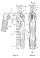
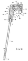
- FIGS. 1-3 show a representative embodiment of a pipette control arrangement 10 , which is adapted to facilitate accurate pipetting of liquids.
- the pipette control arrangement 10 includes a housing assembly 20 , which is preferably molded of a plastic material and which is preferably formed having a substantially inverted L-shaped configuration with a pistol-type grip. To facilitate assembly of the invention and replacement of its elements, the housing assembly 20 is typically made of two portions or halves 21 and 23 .
- the housing assembly 20 includes a neck portion 22 and a handle portion 24 .
- the pipette control arrangement 10 further includes a pipette connector assembly 30 , which is adapted for releasably connecting a pipette 32 to the housing assembly 20 and a pump unit or assembly 40 , which controls the volumetric aspiration and distribution of liquids.
- the connector assembly 30 is shown outwardly extending from the neck portion 22 of the housing assembly 20.
- the configuration of the housing assembly provides the user with enhanced control over the motion and positioning of the pipette 32 and more specifically facilitates accurate positioning of a pipette tip 34 .
- the inverted L-shaped configuration enhances the user's simultaneous visual monitoring of the operation of the pipette control arrangement 10 while monitoring the liquid level 36 in the pipette 32 .
- This ergonomically beneficial configuration also allows the user to maintain a neutral wrist position and minimizes the bending of the wrist up or down or side to side during operation of the pipette control arrangement 10.
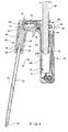
- the connector assembly 30 is formed with a flexible pipette connector 42 , which is preferably made of a resilient material such as rubber or silicone.
- the flexible pipette connector 42 is typically defined by a first end 44 , which is inserted through an extension opening 48 in the neck portion 22 of housing assembly 20 and a second end 46 , which is adapted for operatively receiving the pipette 32 .
- an attachment arrangement which can be in the form of external threads is provided at the opening 48 .
- a longitudinal channel 55 is provided within the connector 42 inter-connecting the first end 44 and the second end 46 .
- a nose cone 50 having an internally threaded first end 52 releasably secures the flexible pipette connector 42 to housing assembly 20 .
- An operational aperture 53 passes through a wall of the connector 42 . We shall revert to this feature later in the application.
- a mouth end 60 of the pipette 32 is inserted into second end 46 of the flexible pipette connector 42 , which includes an expandable opening or channel 54 that can be slightly smaller than the outer diameter of the pipette 32 to be used.
- the channel 54 expands outward and the resiliency of the material operatively holds the pipette 32 tightly in place.
- a seal is formed between the flexible pipette connector 42 and pipette 32 , which prevents the leakage of outside air into the pipette control system 10 and the subsequent leakage of liquid from the pipette tip 34 .
- the pipette connector assembly 30 also serves to position and stabilize the pipette and may include an optional filter (not shown), such as a membrane or hydrophobic filter. As shown in the drawings, the pipette connector assembly 30 is fixed to the neck 22 of housing assembly 20 so as to hold the attached pipette 32 in a position that can be substantially parallel and proximate to the handle portion 24 . Alternatively, the pipette connector assembly 30 may be attached to the neck of the housing assembly 20 by other arrangements. For example, it can be attached by a swivel fitting, enabling the user to change the angle between the pipette 32 and the handle portion 24 .
- an optional filter such as a membrane or hydrophobic filter.
- the pump assembly 40 provides a low pressure vacuum source that aspirates or draws liquid into the pipette 32 , and a high pressure air source that facilitates dispensing of aliquots of liquid from the pipette 32 into a series of wells for testing.
- the pump assembly 40 is operatively connected to the first end 44 of the flexible pipette connector 42 via a connecting arrangement or air tube 70 .
- the cylinder-plunger sub-assembly or unit 80 consists of a plunger 82 , which is slidably movable within a substantially hollow cylinder 84 . This motion is resulted in compression or expansion of air situated in an operational chamber 100 formed within an internal space of the cylinder 84 between the plunger 82 and the bottom 81 of the cylinder.
- the mechanical drive system 90 includes a thumb wheel 92 , which is coaxially connected with a pinion 96 adapted for engagement with a rack member 94 . As clearly illustrated, the rack formation 94 forms a portion of the plunger 82 .
- the thumb wheel 92 is adapted for rotational motion and is both arranged within the interior of the handle portion 24 and exposed to the exterior of the housing assembly 20 , so as to be conveniently accessed by fingers of a user.
- the mechanical drive system 90 is adapted for conversion of the rotational motion of the thumb wheel 92 and the pinion 96 associated therewith to the translational motion of the rack formation 94 and the plunger 82 in a longitudinal direction.
- the mechanical drive system 90 is in the form of a rack and pinion combination, utilization of other forms of driving arrangements is also contemplated.
- the mechanical drive system 90 can be in the form of a gear train.
- the plunger 82 is moved away from the bottom portion 81 of the cylinder 84 (as illustrated by the arrow B ), so that the operational chamber 100 is expanded forming a low pressure or vacuum zone thereinside.
- air or gas is allowed to enter and accumulate in the space of the operational chamber 100 between the bottom portion 81 of the cylinder 84 and the plunger 82 .
- the downward motion of the plunger 82 causes gradual compression and discharge of air or gas from the operational chamber 100 , which is resulted in the increased resistance to the downward motion thereof.
- a suction action is achieved when the thumb wheel 92 is rotated in the opposite (or clockwise) direction causing the plunger 82 to move away from the bottom 81 of the cylinder 84 in the direction of the arrow B .
- the space of the operational chamber 100 within the cylinder 84 increases, so as to facilitate formation of a reduced pressure zone or vacuum thereinside.
- These vacuum forces are conveyed through the connecting arrangement or flexible air tube 70 and extend into the longitudinal channel 55 of the flexible pipette connector 42 via an aperture 102 in the first end 44 .
- the reduced pressure zone or vacuum creates suction within the flexible pipette connector 42 , resulted in the aspiration or drawing of liquid into the pipette 32 from an outside container. In this manner liquid is directed upwardly, thereby partially or completely filling the pipette 32 .
- the pipette control system 10 should be capable of accurately accepting and discharging a very precise volume of the liquid. Because the speed and/or amount of rotational motion of the thumb wheel 92 controls how much or how fast the liquid is drawn or dispensed, the sensitivity and accuracy of the pump assembly 40 may be selected and or adjusted to fit the user's needs by changing certain characteristics of the mechanical drive system 90 . For example, this can be adjusted by changing the gear ratio between the thumb wheel 92 and the mechanical rack assembly 94 . In certain embodiments of the invention, the thumb wheel 92 is removable in nature, which provides the user with an option of using various rack-pinion arrangements having different driving ratios.
- the thumb wheel 92 is coaxially coupled with a pinion 96 having a substantial number of gear teeth
- a second thumb wheel may be coaxially connected with a pinion (not shown) having fewer gear teeth.
- the pinions are engaged to the same mechanical rack assembly 94 , a rotational motion of the first thumb wheel results in a different degree of translational movement of the plunger 82 than would the same degree of rotational motion of the second thumb wheel.
- the thumb wheel and pinion assembly may be held constant while certain characteristics of the mechanical rack assembly are adjusted, thereby allowing a user to achieve similar ranges and control of plunger motion and therefore similar ranges of pipetting accuracy as above-described.
- the versatility of the invention is enhanced when the user can adjust capacity of the device for a particular volume of liquid to be pipetted.
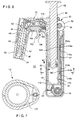
- the housing assembly 20 of the pipette control arrangement 10 in general, and more specifically the interior of the handle portion 24 is formed, so as to be capable of accommodating various types of cylinder-plunger units or assemblies, wherein each unit or assembly is formed having a predetermined volumetric capacity.
- the interior part of the handle portion is adapted to accommodate at least the following three types of cylinders: a first cylinder having the internal or working volume of about 25 ml.; a second cylinder having the approximate internal or working volume of 10 ml.; and a third cylinder having the internal or working volume of about 2 ml.
- a first cylinder having the internal or working volume of about 25 ml. a second cylinder having the approximate internal or working volume of 10 ml.
- a third cylinder having the internal or working volume of about 2 ml.
- the outside periphery and/or diameters of the other cylinders 120 and 130 are smaller than the outer diameter of the first cylinder 110 .
- these smaller cylinders should be stably received within the same interior region of the handle portion 24 in the same manner as the large cylinder 110 .
- the smaller cylinders 120 and 130 are fixedly positioned within the interior of the housing by means of a special securing arrangement as described hereinbelow.
- the interior of the handle portion 24 is separated by a longitudinal partitioner 27 into a main section 29 typically having an arc-shaped cross-section and an auxiliary section 35 .
- the main section 29 is mainly adapted to accommodate the cylinders 110 , 120 , 130
- the auxiliary section 35 is adapted to receive a portion of the air tube 70 longitudinally extending within the handle portion 24 .
- the first cylinder 110 has a substantial outer diameter 112 , such that it occupies almost the entire or a significant portion of the curved interior part of the main section 29 of the handle portion 24 (see Figs. 3-6).
- a second cylinder 120 and a third cylinder 130 are formed having substantially smaller outer diameters 122 , 132 compared with the outer diameter 112 of the first cylinder. However, all cylinders must occupy the same main section 29 of the interior area of the handle portion 24 .
- the smaller cylinders 120 , 130 are formed with the securing arrangement, so as to be received in the same manner as the first cylinder 110 within the interior of the handle portion 24 . As illustrated in FIGS. 6-11, this securing arrangement is in the form of flanges or fins extending outwardly from the exterior wall of each cylinder.
- the smaller cylinders 120 , 130 are each formed with at least a pair of flanges or fins 124a , 124b and 134a , 134b extending outwardly therefrom.
- each fin of the securing arrangement is formed with a stabilizing, arcuatly-shaped part 117 , 137 which is adapted to stabilize the smaller cylinders within the curved interior main section 29 , and an engaging part 119 , 139 which is adapted for engagement with the restrictive ribs 25 extending from an inner wall over the interior of the handle portion 24 .
- the main function of the engaging parts 119 , 139 is to prevent, upon their engagement with the restrictive ribs 140 , 142 , longitudinal movement of the respective cylinder within the interior part of the handle portion 24 .
- the main function of the stabilizing parts 117 , 137 is to compensate for an extra space which became available upon positioning of the smaller cylinders within the main section 29 and to prevent, in combination with the engaging parts, movement of the respective cylinder in the transverse direction.
- the second or intermediate cylinder 120 includes a second pair of fins 126a , 126b (see Fig. 8).
- the first cylinder 110 is formed with two pairs of fins 114a , 116a and 114b , 116b , similar to that of the smaller size cylinders, which operatively form a pair of receiving portions or slots 118a, 118b .
- the slots 118a, 118b engage a pair of restrictive ribs or fins 140, 142 extending from the interior of the handle portion 24 and operated to securely seat the first cylinder 110 within the housing assembly 20 .
- a reverse fin/slot arrangement is also contemplated.
- the interior of the handle portion can be formed with two slots or receiving arrangements for operatively receiving fins provided on the exterior of the first cylinder 110 .
- Formation of the housing assembly 20 having two portions or halves 21, 23 facilitates replacement or substitution of the components of the invention such as the pump assembly 40 , the air tube 70 and/or the pipette connector assembly 30 . Replacement of these elements may be necessitated by contamination thereof by liquid from the pipette 32 , ordinary wear or, as discussed hereinabove, when different capacity or volume of cylinder-plunger arrangement is needed.
- the pump assembly 40 , connecting arrangement or air tube 70 and pipette connector assembly 30 may be manufactured as disposable items and arranged to be readily detachable from one another to facilitate their replacement in the pipette control system 10 .
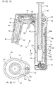
- FIG. 12 wherein an alternate embodiment of the present invention is shown.
- the above-discussed thumb-wheel arrangement 92 associated with the mechanical drive system 90 is utilized. In this manner the liquid can be dispensed in a controlled, drop by drop fashion.
- a quick release mechanism 150 (see Fig. 12, for example) is activated.
- the quick release mechanism 150 includes a plug or engaging member 151 , formed with a first engaging end 160 operatively associated with the pipette connector assembly 30 and a second engaging end 162 operatively associated with a biasing member or spring arrangement 170 .
- a trigger 152 extends outwardly from the plug or engaging member 154 , so as to pass through a wall of a guiding chamber 153 .
- the engaging plug or member 154 is adapted for slidable movement between open and closed positions and vice versa in the direction transverse to the longitudinal channel 55 within the guiding chamber 153 formed at a bottom area of the neck portion 22.
- the first end 160 is adapted to be snugly received within and sealingly close the operational aperture 53 provided within the flexible pipette connector 42 .
- the operational passage of the apparatus of the invention which encompasses the interior area of the pipette 32 , the longitudinal channel 55 and the air tube 70 is sealed from an outside environment. This condition is required for the gradual discharge of the liquid by means of operation of the thumb-wheel arrangement 92 .
- the quick release mechanism 150 When the quick release mechanism 150 is actuated by a user pulling the trigger 152 , and the plug or engaging member 154 is moved from the closed to the open position thereof, causing the compression of the spring arrangement 170 , so as to allow the first engaging end 160 to disengage the operational aperture 53 .
- This enables the longitudinal channel 55 formed in the interior of the flexible pipette connector 42 to communicate with the ambient atmosphere.
- the vacuum existing in the operational passage is released. In this manner the forces of gravity facilitate quick dispensing of a liquid from the pipette 32 .
- the trigger 152 In order to return to the controlled handling of liquid by the thumb-wheel arrangement 92 , associated with the mechanical drive system 90 , the trigger 152 is released. In this condition the biasing member or spring 170 presses the plug or engaging member 154 toward the pipette connector assembly 30 and the first engaging end 160 sealingly closes the operational aperture 53 in the flexible pipette connector 42 . Thus, the vacuum or low pressure condition can be reestablished in the operational passage of the apparatus.
- the quick release mechanism 150 can be efficiently utilized, so as to release the vacuum within the pipette connector assembly 30 and the pipette 32 .
- a trigger 152 By actuating a trigger 152 , a plug 154 , which seals the pipette connector assembly 30 , is pulled back. This motion opens the operational aperture 53 in the flexible pipette connector 42 and releases the vacuum, so that the gravity takes over and it releases/discharges the liquid out of the pipette 32 .
Landscapes
- Health & Medical Sciences (AREA)
- Clinical Laboratory Science (AREA)
- Chemical & Material Sciences (AREA)
- Chemical Kinetics & Catalysis (AREA)
- Devices For Use In Laboratory Experiments (AREA)
- Sampling And Sample Adjustment (AREA)
- Feeding, Discharge, Calcimining, Fusing, And Gas-Generation Devices (AREA)
Priority Applications (1)
| Application Number | Priority Date | Filing Date | Title |
|---|---|---|---|
| EP07000018A EP1775023A1 (fr) | 2003-05-12 | 2004-04-20 | Agencement de contrôle de pipette |
Applications Claiming Priority (2)
| Application Number | Priority Date | Filing Date | Title |
|---|---|---|---|
| US10/435,863 US7093507B2 (en) | 2003-05-12 | 2003-05-12 | Pipette control arrangement |
| US435863 | 2003-05-12 |
Related Child Applications (1)
| Application Number | Title | Priority Date | Filing Date |
|---|---|---|---|
| EP07000018A Division EP1775023A1 (fr) | 2003-05-12 | 2004-04-20 | Agencement de contrôle de pipette |
Publications (3)
| Publication Number | Publication Date |
|---|---|
| EP1477227A2 true EP1477227A2 (fr) | 2004-11-17 |
| EP1477227A3 EP1477227A3 (fr) | 2004-12-08 |
| EP1477227B1 EP1477227B1 (fr) | 2007-01-03 |
Family
ID=33029764
Family Applications (2)
| Application Number | Title | Priority Date | Filing Date |
|---|---|---|---|
| EP04252316A Expired - Lifetime EP1477227B1 (fr) | 2003-05-12 | 2004-04-20 | Dispositif de régulation de pipettes |
| EP07000018A Withdrawn EP1775023A1 (fr) | 2003-05-12 | 2004-04-20 | Agencement de contrôle de pipette |
Family Applications After (1)
| Application Number | Title | Priority Date | Filing Date |
|---|---|---|---|
| EP07000018A Withdrawn EP1775023A1 (fr) | 2003-05-12 | 2004-04-20 | Agencement de contrôle de pipette |
Country Status (10)
| Country | Link |
|---|---|
| US (1) | US7093507B2 (fr) |
| EP (2) | EP1477227B1 (fr) |
| JP (1) | JP4884653B2 (fr) |
| KR (1) | KR20040097924A (fr) |
| CN (1) | CN1572369B (fr) |
| AT (1) | ATE350164T1 (fr) |
| AU (1) | AU2004201909B8 (fr) |
| CA (1) | CA2466256C (fr) |
| DE (1) | DE602004003993T2 (fr) |
| TW (1) | TWI311925B (fr) |
Cited By (1)
| Publication number | Priority date | Publication date | Assignee | Title |
|---|---|---|---|---|
| FR2917648A1 (fr) * | 2007-06-25 | 2008-12-26 | Gilson Sas Soc Par Actions Sim | Pipette permettant un prelevement de liquide par mouvement de va-et-vient du piston. |
Families Citing this family (17)
| Publication number | Priority date | Publication date | Assignee | Title |
|---|---|---|---|---|
| PL200761B1 (pl) * | 2003-07-24 | 2009-02-27 | Pz Htl Spo & Lstrok Ka Akcyjna | Zespół wyrzutnika wymiennej końcówki w pipecie |
| US20080223209A1 (en) * | 2007-03-16 | 2008-09-18 | Tricontinent Scientific | Syringe barrel wiper for liquid dispensing |
| FR2920675B1 (fr) * | 2007-09-10 | 2010-12-03 | Gilson Sas | Systeme de pipetage multicanaux comprenant un porte-pistons a guidage ameliore |
| CN102414550B (zh) | 2009-04-27 | 2014-07-16 | Ei频谱有限责任公司 | 移液器仪器 |
| US9632102B2 (en) | 2011-09-25 | 2017-04-25 | Theranos, Inc. | Systems and methods for multi-purpose analysis |
| US8475739B2 (en) | 2011-09-25 | 2013-07-02 | Theranos, Inc. | Systems and methods for fluid handling |
| US20140170735A1 (en) | 2011-09-25 | 2014-06-19 | Elizabeth A. Holmes | Systems and methods for multi-analysis |
| US9664702B2 (en) | 2011-09-25 | 2017-05-30 | Theranos, Inc. | Fluid handling apparatus and configurations |
| US10012664B2 (en) | 2011-09-25 | 2018-07-03 | Theranos Ip Company, Llc | Systems and methods for fluid and component handling |
| US9810704B2 (en) | 2013-02-18 | 2017-11-07 | Theranos, Inc. | Systems and methods for multi-analysis |
| KR20150115391A (ko) * | 2014-04-04 | 2015-10-14 | 쓰리엠 이노베이티브 프로퍼티즈 캄파니 | 피펫 장치 |
| DE202017101009U1 (de) * | 2017-02-23 | 2018-05-24 | Brand Gmbh + Co Kg | Anbringen und Lösen einer Kolben-Zylinder-Einheit an bzw. von einem Dispenser zum Aufnehmen und Abgeben von Fluidvolumina |
| WO2019005833A1 (fr) | 2017-06-26 | 2019-01-03 | Mendoza Estevan | Dispositif de filtration d'échantillons |
| DE102017117789A1 (de) * | 2017-08-04 | 2019-02-07 | Als Automated Lab Solutions Gmbh | Adapter zur Aufnahme einer Kapillare und dessen Verwendung |
| EP3928868A1 (fr) * | 2020-06-22 | 2021-12-29 | Eppendorf AG | Pipette à utiliser avec une pointe de pipette ou une seringue comportant un piston et un cylindre |
| KR102578537B1 (ko) | 2021-02-24 | 2023-09-13 | 충남대학교산학협력단 | 피펫 사용을 위한 흔들림 제어 장치 |
| CN113976198A (zh) * | 2021-10-29 | 2022-01-28 | 美东汇成生命科技(昆山)有限公司 | 一种多功能移液吸头 |
Citations (7)
| Publication number | Priority date | Publication date | Assignee | Title |
|---|---|---|---|---|
| US3954014A (en) * | 1974-12-16 | 1976-05-04 | Becton, Dickinson And Company | Multiple shot pipetter |
| US3963061A (en) * | 1975-09-16 | 1976-06-15 | Drummond Scientific Company | Apparatus for drawing liquids into, and expelling liquids from a pipette |
| US4257268A (en) * | 1979-08-24 | 1981-03-24 | Data Packaging Corporation | Pipetter |
| US4304138A (en) * | 1979-01-23 | 1981-12-08 | Kommandiittiyhtio Finnpipette Osmo A. Suovaniemi | Multi-dose pipette |
| US4988481A (en) * | 1989-01-30 | 1991-01-29 | Labsystems Oy | Electrical pipette |
| US5104624A (en) * | 1989-10-20 | 1992-04-14 | Costar Corporation | Pipetter |
| EP0873790A2 (fr) * | 1997-04-24 | 1998-10-28 | Walu Labortechnik GmbH | Pipette |
Family Cites Families (23)
| Publication number | Priority date | Publication date | Assignee | Title |
|---|---|---|---|---|
| US2517796A (en) | 1945-11-28 | 1950-08-08 | Waddy T Mathis | Liquid-measuring dispenser |
| US3660037A (en) * | 1970-08-10 | 1972-05-02 | Kurt Rudolf Sokol | Device for measuring blood sedimentation rate |
| DE2851532C2 (de) | 1978-11-29 | 1981-02-19 | Boehringer Mannheim Gmbh, 6800 Mannheim | Pipette mit elastischem Balg |
| US4527437A (en) * | 1983-07-06 | 1985-07-09 | Wescor, Inc. | Pipette controller |
| CN86210246U (zh) * | 1986-12-15 | 1988-03-16 | 楼许柏 | 多用吸液器 |
| US4926717A (en) | 1989-09-05 | 1990-05-22 | Manostat Corporation | Bottle uncapping and recapping machine |
| US5090255A (en) * | 1990-03-27 | 1992-02-25 | Drummond Scientific Company | Programmable pipet apparatus |
| DE4141608C2 (de) | 1991-12-17 | 1993-12-02 | Eppendorf Geraetebau Netheler | Pipettiervorrichtung |
| US5294405A (en) * | 1992-04-09 | 1994-03-15 | Drummond Scientific Company | Adjustable valve for pipette gun |
| FI922939A0 (fi) * | 1992-06-24 | 1992-06-24 | Labsystems Oy | Knappipett. |
| US5364596A (en) | 1992-12-01 | 1994-11-15 | Rainin Instrument Co., Inc. | Manual pipette with plunger velocity governor, home position latch and trigger release |
| US5509318A (en) | 1993-10-13 | 1996-04-23 | Manostat Corporation | Memory Mopet |
| FR2723700B1 (fr) | 1994-08-16 | 1996-11-15 | Marteau D Autry Eric | Pipette pour distribuer des volumes successifs de liquide |
| FI951766A0 (fi) | 1995-04-12 | 1995-04-12 | Labsystems Oy | Faspipett |
| JP3699749B2 (ja) | 1995-06-09 | 2005-09-28 | セーラー万年筆株式会社 | ピペット |
| US5650124A (en) | 1995-07-24 | 1997-07-22 | Gilson; Warren E. | Adjustable pipette |
| US5616871A (en) | 1995-09-28 | 1997-04-01 | Drummond Scientific Company | Pipet gun assembly |
| US5849248A (en) | 1996-03-05 | 1998-12-15 | Rainin Instrument Co., Inc. | Adjustable volume pipette with improved volume adjustment lock mechanism |
| FI961649A0 (fi) | 1996-04-15 | 1996-04-15 | Labsystems Oy | Spaerrpipett |
| US5983733A (en) | 1996-11-15 | 1999-11-16 | Hamilton Company | Manual pipette |
| FI105783B (fi) | 1998-08-26 | 2000-10-13 | Biohit Oyj | Menetelmä ja laite nesteen annostelemiseksi |
| US6299841B1 (en) | 1999-03-05 | 2001-10-09 | Rainin Instrument Co., Inc. | Bilaterally symmetrical battery powered microprocessor controlled lightweight hand-holdable electronic pipette |
| US6365110B1 (en) | 2000-03-09 | 2002-04-02 | Rainin Instrument | Blowout springless manual air displacement pipette with mechanical assist for aiding in locating and maintaining pipette plunger at a home position |
-
2003
- 2003-05-12 US US10/435,863 patent/US7093507B2/en not_active Expired - Lifetime
-
2004
- 2004-04-20 AT AT04252316T patent/ATE350164T1/de not_active IP Right Cessation
- 2004-04-20 EP EP04252316A patent/EP1477227B1/fr not_active Expired - Lifetime
- 2004-04-20 DE DE602004003993T patent/DE602004003993T2/de not_active Expired - Lifetime
- 2004-04-20 EP EP07000018A patent/EP1775023A1/fr not_active Withdrawn
- 2004-04-23 TW TW093111418A patent/TWI311925B/zh active
- 2004-05-03 CA CA2466256A patent/CA2466256C/fr not_active Expired - Lifetime
- 2004-05-05 AU AU2004201909A patent/AU2004201909B8/en not_active Ceased
- 2004-05-11 KR KR1020040033193A patent/KR20040097924A/ko not_active Application Discontinuation
- 2004-05-11 JP JP2004141362A patent/JP4884653B2/ja not_active Expired - Fee Related
- 2004-05-12 CN CN2004100435851A patent/CN1572369B/zh not_active Expired - Fee Related
Patent Citations (7)
| Publication number | Priority date | Publication date | Assignee | Title |
|---|---|---|---|---|
| US3954014A (en) * | 1974-12-16 | 1976-05-04 | Becton, Dickinson And Company | Multiple shot pipetter |
| US3963061A (en) * | 1975-09-16 | 1976-06-15 | Drummond Scientific Company | Apparatus for drawing liquids into, and expelling liquids from a pipette |
| US4304138A (en) * | 1979-01-23 | 1981-12-08 | Kommandiittiyhtio Finnpipette Osmo A. Suovaniemi | Multi-dose pipette |
| US4257268A (en) * | 1979-08-24 | 1981-03-24 | Data Packaging Corporation | Pipetter |
| US4988481A (en) * | 1989-01-30 | 1991-01-29 | Labsystems Oy | Electrical pipette |
| US5104624A (en) * | 1989-10-20 | 1992-04-14 | Costar Corporation | Pipetter |
| EP0873790A2 (fr) * | 1997-04-24 | 1998-10-28 | Walu Labortechnik GmbH | Pipette |
Cited By (4)
| Publication number | Priority date | Publication date | Assignee | Title |
|---|---|---|---|---|
| FR2917648A1 (fr) * | 2007-06-25 | 2008-12-26 | Gilson Sas Soc Par Actions Sim | Pipette permettant un prelevement de liquide par mouvement de va-et-vient du piston. |
| WO2009000860A1 (fr) * | 2007-06-25 | 2008-12-31 | Gilson Sas | Pipette permettant un prelevement de liquide par mouvement de va-et-vient du piston |
| US8117927B2 (en) | 2007-06-25 | 2012-02-21 | Gilson Sas | Pipette providing sampling via back-and-forth movement of the piston |
| KR101449086B1 (ko) * | 2007-06-25 | 2014-10-08 | 질송 에스.아.에스. | 피스톤의 전후 운동에 의한 샘플링을 제공하는 피펫 |
Also Published As
| Publication number | Publication date |
|---|---|
| EP1775023A1 (fr) | 2007-04-18 |
| DE602004003993T2 (de) | 2007-06-21 |
| JP4884653B2 (ja) | 2012-02-29 |
| TW200505578A (en) | 2005-02-16 |
| EP1477227B1 (fr) | 2007-01-03 |
| AU2004201909B8 (en) | 2009-11-26 |
| DE602004003993D1 (de) | 2007-02-15 |
| AU2004201909A1 (en) | 2004-12-02 |
| US7093507B2 (en) | 2006-08-22 |
| JP2004337852A (ja) | 2004-12-02 |
| CN1572369B (zh) | 2010-06-09 |
| ATE350164T1 (de) | 2007-01-15 |
| US20040226389A1 (en) | 2004-11-18 |
| TWI311925B (en) | 2009-07-11 |
| AU2004201909B2 (en) | 2009-11-19 |
| CA2466256A1 (fr) | 2004-11-12 |
| CA2466256C (fr) | 2013-07-09 |
| EP1477227A3 (fr) | 2004-12-08 |
| CN1572369A (zh) | 2005-02-02 |
| KR20040097924A (ko) | 2004-11-18 |
Similar Documents
| Publication | Publication Date | Title |
|---|---|---|
| EP1477227B1 (fr) | Dispositif de régulation de pipettes | |
| US3405843A (en) | Container-dispenser for collapsible tubes | |
| US5456672A (en) | Syringe-like device for the dosing of liquids or pastes | |
| US3855867A (en) | Liquid transfer pipetting device | |
| US8117927B2 (en) | Pipette providing sampling via back-and-forth movement of the piston | |
| US9028774B2 (en) | Pipetting apparatus and method for production thereof | |
| US3982899A (en) | Fluid handling apparatus | |
| CA2016485A1 (fr) | Pompe a pipette | |
| US6253628B1 (en) | Apparatus for drawing liquids into and expelling liquids from a pipet at variable flow rates | |
| US20100209303A1 (en) | Pipette Device and Method of Manufacture and Use Thereof | |
| CN213726594U (zh) | 定量式取样试管 | |
| US4294125A (en) | Pipette controller with graduate reading plunger and lever assembly for gravity drainage | |
| US20040084482A1 (en) | Fluid dispensing apparatus | |
| US3881360A (en) | Measuring dispensing device | |
| EP0202022A2 (fr) | Dispositif hydraulique de distribution de liquide | |
| US20200309583A1 (en) | Handheld solids dispenser | |
| US3250441A (en) | Liquid-dispensing apparatus | |
| JP6885949B2 (ja) | 滴下装置及びそれを形成する方法 | |
| JPH11165080A (ja) | ピペットガン | |
| KR100624492B1 (ko) | 피펫 | |
| WO2013005224A1 (fr) | Dispositif de commande d'une pipette | |
| KR100624491B1 (ko) | 연필형 피펫 | |
| FR2495317A1 (fr) | Dispositif a seringue destine au prelevement et a la distribution de quantites predeterminees de liquides et actionne par verin pneumatique ou hydraulique |
Legal Events
| Date | Code | Title | Description |
|---|---|---|---|
| PUAI | Public reference made under article 153(3) epc to a published international application that has entered the european phase |
Free format text: ORIGINAL CODE: 0009012 |
|
| PUAL | Search report despatched |
Free format text: ORIGINAL CODE: 0009013 |
|
| AK | Designated contracting states |
Kind code of ref document: A2 Designated state(s): AT BE BG CH CY CZ DE DK EE ES FI FR GB GR HU IE IT LI LU MC NL PL PT RO SE SI SK TR |
|
| AX | Request for extension of the european patent |
Extension state: AL HR LT LV MK |
|
| AK | Designated contracting states |
Kind code of ref document: A3 Designated state(s): AT BE BG CH CY CZ DE DK EE ES FI FR GB GR HU IE IT LI LU MC NL PL PT RO SE SI SK TR |
|
| AX | Request for extension of the european patent |
Extension state: AL HR LT LV MK |
|
| 17P | Request for examination filed |
Effective date: 20050606 |
|
| AKX | Designation fees paid |
Designated state(s): AT BE BG CH CY CZ DE DK EE ES FI FR GB GR HU IE IT LI LU MC NL PL PT RO SE SI SK TR |
|
| GRAP | Despatch of communication of intention to grant a patent |
Free format text: ORIGINAL CODE: EPIDOSNIGR1 |
|
| GRAS | Grant fee paid |
Free format text: ORIGINAL CODE: EPIDOSNIGR3 |
|
| GRAA | (expected) grant |
Free format text: ORIGINAL CODE: 0009210 |
|
| AK | Designated contracting states |
Kind code of ref document: B1 Designated state(s): AT BE BG CH CY CZ DE DK EE ES FI FR GB GR HU IE IT LI LU MC NL PL PT RO SE SI SK TR |
|
| PG25 | Lapsed in a contracting state [announced via postgrant information from national office to epo] |
Ref country code: FI Free format text: LAPSE BECAUSE OF FAILURE TO SUBMIT A TRANSLATION OF THE DESCRIPTION OR TO PAY THE FEE WITHIN THE PRESCRIBED TIME-LIMIT Effective date: 20070103 Ref country code: AT Free format text: LAPSE BECAUSE OF FAILURE TO SUBMIT A TRANSLATION OF THE DESCRIPTION OR TO PAY THE FEE WITHIN THE PRESCRIBED TIME-LIMIT Effective date: 20070103 Ref country code: NL Free format text: LAPSE BECAUSE OF FAILURE TO SUBMIT A TRANSLATION OF THE DESCRIPTION OR TO PAY THE FEE WITHIN THE PRESCRIBED TIME-LIMIT Effective date: 20070103 Ref country code: SI Free format text: LAPSE BECAUSE OF FAILURE TO SUBMIT A TRANSLATION OF THE DESCRIPTION OR TO PAY THE FEE WITHIN THE PRESCRIBED TIME-LIMIT Effective date: 20070103 Ref country code: CH Free format text: LAPSE BECAUSE OF FAILURE TO SUBMIT A TRANSLATION OF THE DESCRIPTION OR TO PAY THE FEE WITHIN THE PRESCRIBED TIME-LIMIT Effective date: 20070103 Ref country code: DK Free format text: LAPSE BECAUSE OF FAILURE TO SUBMIT A TRANSLATION OF THE DESCRIPTION OR TO PAY THE FEE WITHIN THE PRESCRIBED TIME-LIMIT Effective date: 20070103 Ref country code: LI Free format text: LAPSE BECAUSE OF FAILURE TO SUBMIT A TRANSLATION OF THE DESCRIPTION OR TO PAY THE FEE WITHIN THE PRESCRIBED TIME-LIMIT Effective date: 20070103 Ref country code: PL Free format text: LAPSE BECAUSE OF FAILURE TO SUBMIT A TRANSLATION OF THE DESCRIPTION OR TO PAY THE FEE WITHIN THE PRESCRIBED TIME-LIMIT Effective date: 20070103 |
|
| REG | Reference to a national code |
Ref country code: GB Ref legal event code: FG4D |
|
| REF | Corresponds to: |
Ref document number: 602004003993 Country of ref document: DE Date of ref document: 20070215 Kind code of ref document: P |
|
| REG | Reference to a national code |
Ref country code: IE Ref legal event code: FG4D |
|
| PG25 | Lapsed in a contracting state [announced via postgrant information from national office to epo] |
Ref country code: SE Free format text: LAPSE BECAUSE OF FAILURE TO SUBMIT A TRANSLATION OF THE DESCRIPTION OR TO PAY THE FEE WITHIN THE PRESCRIBED TIME-LIMIT Effective date: 20070403 |
|
| PG25 | Lapsed in a contracting state [announced via postgrant information from national office to epo] |
Ref country code: BG Free format text: LAPSE BECAUSE OF FAILURE TO SUBMIT A TRANSLATION OF THE DESCRIPTION OR TO PAY THE FEE WITHIN THE PRESCRIBED TIME-LIMIT Effective date: 20070404 |
|
| PG25 | Lapsed in a contracting state [announced via postgrant information from national office to epo] |
Ref country code: ES Free format text: LAPSE BECAUSE OF FAILURE TO SUBMIT A TRANSLATION OF THE DESCRIPTION OR TO PAY THE FEE WITHIN THE PRESCRIBED TIME-LIMIT Effective date: 20070414 |
|
| ET | Fr: translation filed | ||
| PG25 | Lapsed in a contracting state [announced via postgrant information from national office to epo] |
Ref country code: PT Free format text: LAPSE BECAUSE OF FAILURE TO SUBMIT A TRANSLATION OF THE DESCRIPTION OR TO PAY THE FEE WITHIN THE PRESCRIBED TIME-LIMIT Effective date: 20070604 |
|
| NLV1 | Nl: lapsed or annulled due to failure to fulfill the requirements of art. 29p and 29m of the patents act | ||
| REG | Reference to a national code |
Ref country code: CH Ref legal event code: PL |
|
| PLBE | No opposition filed within time limit |
Free format text: ORIGINAL CODE: 0009261 |
|
| STAA | Information on the status of an ep patent application or granted ep patent |
Free format text: STATUS: NO OPPOSITION FILED WITHIN TIME LIMIT |
|
| PG25 | Lapsed in a contracting state [announced via postgrant information from national office to epo] |
Ref country code: SK Free format text: LAPSE BECAUSE OF FAILURE TO SUBMIT A TRANSLATION OF THE DESCRIPTION OR TO PAY THE FEE WITHIN THE PRESCRIBED TIME-LIMIT Effective date: 20070103 |
|
| 26N | No opposition filed |
Effective date: 20071005 |
|
| PG25 | Lapsed in a contracting state [announced via postgrant information from national office to epo] |
Ref country code: CZ Free format text: LAPSE BECAUSE OF FAILURE TO SUBMIT A TRANSLATION OF THE DESCRIPTION OR TO PAY THE FEE WITHIN THE PRESCRIBED TIME-LIMIT Effective date: 20070103 Ref country code: BE Free format text: LAPSE BECAUSE OF FAILURE TO SUBMIT A TRANSLATION OF THE DESCRIPTION OR TO PAY THE FEE WITHIN THE PRESCRIBED TIME-LIMIT Effective date: 20070103 Ref country code: RO Free format text: LAPSE BECAUSE OF FAILURE TO SUBMIT A TRANSLATION OF THE DESCRIPTION OR TO PAY THE FEE WITHIN THE PRESCRIBED TIME-LIMIT Effective date: 20070103 |
|
| PG25 | Lapsed in a contracting state [announced via postgrant information from national office to epo] |
Ref country code: GR Free format text: LAPSE BECAUSE OF FAILURE TO SUBMIT A TRANSLATION OF THE DESCRIPTION OR TO PAY THE FEE WITHIN THE PRESCRIBED TIME-LIMIT Effective date: 20070404 |
|
| PG25 | Lapsed in a contracting state [announced via postgrant information from national office to epo] |
Ref country code: IE Free format text: LAPSE BECAUSE OF NON-PAYMENT OF DUE FEES Effective date: 20070420 |
|
| PG25 | Lapsed in a contracting state [announced via postgrant information from national office to epo] |
Ref country code: EE Free format text: LAPSE BECAUSE OF FAILURE TO SUBMIT A TRANSLATION OF THE DESCRIPTION OR TO PAY THE FEE WITHIN THE PRESCRIBED TIME-LIMIT Effective date: 20070103 |
|
| PG25 | Lapsed in a contracting state [announced via postgrant information from national office to epo] |
Ref country code: MC Free format text: LAPSE BECAUSE OF NON-PAYMENT OF DUE FEES Effective date: 20070430 |
|
| PG25 | Lapsed in a contracting state [announced via postgrant information from national office to epo] |
Ref country code: CY Free format text: LAPSE BECAUSE OF FAILURE TO SUBMIT A TRANSLATION OF THE DESCRIPTION OR TO PAY THE FEE WITHIN THE PRESCRIBED TIME-LIMIT Effective date: 20070103 |
|
| PG25 | Lapsed in a contracting state [announced via postgrant information from national office to epo] |
Ref country code: LU Free format text: LAPSE BECAUSE OF NON-PAYMENT OF DUE FEES Effective date: 20070420 |
|
| PG25 | Lapsed in a contracting state [announced via postgrant information from national office to epo] |
Ref country code: HU Free format text: LAPSE BECAUSE OF FAILURE TO SUBMIT A TRANSLATION OF THE DESCRIPTION OR TO PAY THE FEE WITHIN THE PRESCRIBED TIME-LIMIT Effective date: 20070704 Ref country code: TR Free format text: LAPSE BECAUSE OF FAILURE TO SUBMIT A TRANSLATION OF THE DESCRIPTION OR TO PAY THE FEE WITHIN THE PRESCRIBED TIME-LIMIT Effective date: 20070103 |
|
| PGFP | Annual fee paid to national office [announced via postgrant information from national office to epo] |
Ref country code: GB Payment date: 20140416 Year of fee payment: 11 |
|
| PGFP | Annual fee paid to national office [announced via postgrant information from national office to epo] |
Ref country code: DE Payment date: 20140430 Year of fee payment: 11 Ref country code: FR Payment date: 20140409 Year of fee payment: 11 Ref country code: IT Payment date: 20140418 Year of fee payment: 11 |
|
| REG | Reference to a national code |
Ref country code: DE Ref legal event code: R119 Ref document number: 602004003993 Country of ref document: DE |
|
| GBPC | Gb: european patent ceased through non-payment of renewal fee |
Effective date: 20150420 |
|
| PG25 | Lapsed in a contracting state [announced via postgrant information from national office to epo] |
Ref country code: IT Free format text: LAPSE BECAUSE OF NON-PAYMENT OF DUE FEES Effective date: 20150420 Ref country code: DE Free format text: LAPSE BECAUSE OF NON-PAYMENT OF DUE FEES Effective date: 20151103 Ref country code: GB Free format text: LAPSE BECAUSE OF NON-PAYMENT OF DUE FEES Effective date: 20150420 |
|
| REG | Reference to a national code |
Ref country code: FR Ref legal event code: ST Effective date: 20151231 |
|
| PG25 | Lapsed in a contracting state [announced via postgrant information from national office to epo] |
Ref country code: FR Free format text: LAPSE BECAUSE OF NON-PAYMENT OF DUE FEES Effective date: 20150430 |