EP1476917B1 - Phasenarray antenne mit archimedischem spiralelementarray und damit zusammenhängende verfahren - Google Patents
Phasenarray antenne mit archimedischem spiralelementarray und damit zusammenhängende verfahren Download PDFInfo
- Publication number
- EP1476917B1 EP1476917B1 EP03774448A EP03774448A EP1476917B1 EP 1476917 B1 EP1476917 B1 EP 1476917B1 EP 03774448 A EP03774448 A EP 03774448A EP 03774448 A EP03774448 A EP 03774448A EP 1476917 B1 EP1476917 B1 EP 1476917B1
- Authority
- EP
- European Patent Office
- Prior art keywords
- phased array
- array antenna
- antenna elements
- archimedean spiral
- spacing
- Prior art date
- Legal status (The legal status is an assumption and is not a legal conclusion. Google has not performed a legal analysis and makes no representation as to the accuracy of the status listed.)
- Expired - Lifetime
Links
- 238000000034 method Methods 0.000 title claims description 10
- 239000000758 substrate Substances 0.000 claims description 15
- 238000013461 design Methods 0.000 description 10
- 238000003491 array Methods 0.000 description 4
- 230000008901 benefit Effects 0.000 description 3
- 230000005540 biological transmission Effects 0.000 description 3
- 238000013459 approach Methods 0.000 description 2
- 238000012986 modification Methods 0.000 description 2
- 230000004048 modification Effects 0.000 description 2
- 230000004044 response Effects 0.000 description 2
- 230000001154 acute effect Effects 0.000 description 1
- 230000003044 adaptive effect Effects 0.000 description 1
- 230000015572 biosynthetic process Effects 0.000 description 1
- 230000001413 cellular effect Effects 0.000 description 1
- 230000008859 change Effects 0.000 description 1
- 238000010586 diagram Methods 0.000 description 1
- 230000003292 diminished effect Effects 0.000 description 1
- 238000012545 processing Methods 0.000 description 1
- 238000000926 separation method Methods 0.000 description 1
- 238000007493 shaping process Methods 0.000 description 1
- 238000003786 synthesis reaction Methods 0.000 description 1
Images


Classifications
-
- H—ELECTRICITY
- H01—ELECTRIC ELEMENTS
- H01Q—ANTENNAS, i.e. RADIO AERIALS
- H01Q21/00—Antenna arrays or systems
- H01Q21/06—Arrays of individually energised antenna units similarly polarised and spaced apart
- H01Q21/22—Antenna units of the array energised non-uniformly in amplitude or phase, e.g. tapered array or binomial array
Definitions
- the present invention relates to the field of communications, and, more particularly, to phased array antennas and related methods.
- Antenna systems are widely used in both ground based applications (e.g., cellular antennas) and airborne applications (e.g., airplane or satellite antennas).
- ground based applications e.g., cellular antennas
- airborne applications e.g., airplane or satellite antennas.
- so-called “smart” antenna systems such as adaptive or phased array antenna systems, combine the outputs of multiple antenna elements with signal processing capabilities to transmit and/or receive communications signals (e.g., microwave signals, RF signals, etc.).
- communications signals e.g., microwave signals, RF signals, etc.
- Such antenna systems can vary the transmission or reception pattern (i.e., "beam shaping") or direction (i.e., "beam steering”) of the communications signals in response to the signal environment to improve performance characteristics.
- the density of antenna elements in phased array antennas continues to increase. While significant advantages may be realized by having an increased amount of antenna elements within the same surface area, there are potential drawbacks to grouping a large number of antenna elements too close together.
- signal side lobes may result with certain antennas. These side lobes may cause undesirable interference with the main signal beam. In certain circumstances, side lobes may even have an intensity or gain equal to that of the main signal beam, which are commonly referred to as “grating lobes", and are particularly problematic.
- phased array antenna structure described in the above patent provides a significant advancement in the art
- one difficulty in working with aperiodic arrays is that the design necessarily changes as the number of antenna elements to be used changes. That is, when the number of antenna elements is changed from one design to the next, so too will the angles and relative spacing between the antenna elements change.
- aperiodic arrays are not easily scalable from one application to the next, and extensive ad hoc or re-design may therefore be required with each new application.
- calculation of the numerous angles and locations that may be required can be quite cumbersome.
- U.S. Patent No. 5,838,284 to Dougherty discloses a phased array antenna including antenna elements arranged in the shape of a logarithmic (i.e., equiangular) spiral. While such a design may be less cumbersome to design than an aperiodic array, when such an antenna is used for beam steering it may still suffer from high gain side lobes or even grating lobes at wide scan angles.
- phased array antenna having an array which reduces occurrences of grating and/or high gain side lobes yet is relatively easily scalable for numerous applications.
- a phased array antenna which may include a substrate and a plurality of spaced apart phased array antenna elements carried by the substrate and arranged along an imaginary Archimedean spiral. More particularly, the imaginary Archimedean spiral may include a plurality of levels, and a spacing between adjacent pairs of phased array antenna elements along the imaginary Archimedean spiral may be substantially equal to a radial spacing between adjacent levels.
- the phased array antenna may have an operating wavelength ⁇ , and a spacing between adjacent pairs of phased array antenna elements may be less than about 10 ⁇ .
- the plurality of phased array antenna elements may have a substantially equal spacing along the imaginary Archimedean spiral, and the substantially equal spacing may also be less than about 10 ⁇ .
- the plurality of phased array antenna elements may include greater than about 20 phased array antenna elements. Further, substantially all of the plurality of phased array antenna elements may be along the imaginary Archimedean spiral.
- the phased array antenna may further include at least one controller for cooperating with the plurality of phased array antenna elements to provide beam steering.
- the at least one controller may include a plurality of element controllers each connected to at least one of the phased array antenna elements, and a central controller connected to the plurality of element controllers.
- a method aspect of the invention is for making the phased array antenna as briefly described above.
- the method may include providing a substrate and arranging a plurality of phased array antenna elements on the substrate along an imaginary Archimedean spiral.
- the Archimedean spiral may include a plurality of levels, and arranging may include setting a spacing between adjacent pairs of phased array antenna elements along the imaginary Archimedean spiral to be substantially equal to a radial spacing between adjacent levels.
- arranging may include arranging the plurality of phased array antenna elements to have spacing between adjacent pairs thereof of less than about 10 ⁇ , for example, where ⁇ is an operating wavelength of the phased array antenna.
- arranging may include arranging the plurality of phased array antenna elements to have a substantially equal spacing along the imaginary Archimedean spiral, which may also be less than about 10 ⁇ .
- a number of the phased array antenna elements may be in a range of about 20 to 200, for example.
- arranging may include arranging substantially all of the plurality of phased array antenna elements along the imaginary Archimedean spiral.
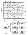
- a phased array antenna 10 includes a substrate 11 and a plurality of spaced apart phased array antenna elements 12 carried by the substrate.
- substrate refers to any surface, mechanized structure, etc., which is suitable for carrying a phased array antenna element, as will be appreciated by those of skill in the art.
- the antenna elements 12 are advantageously arranged along an imaginary Archimedean spiral 13 . More preferably, substantially all of the plurality of phased array antenna elements 12 are along the imaginary Archimedean spiral 13 , although other arrangements may be used in some embodiments.
- the particular shape of a given Archimedean spiral is defined by the selection of the number N.
- N is equal to 1, which is also known as an Archimedes spiral.
- the Archimedes spiral has an equal radial spacing ( x in the illustrated example) between levels 14-17 of the imaginary Archimedean spiral 13.
- the value a determines how tightly wound the spiral is. That is, the value a determines what the spacing x will be, as will be appreciated by those of skill in the art.
- This symmetry may be contrasted with the logarithmic spiral used in some prior art antenna arrays, as discussed above. Excepting the special case of a circle where there is only one level, outer levels of a logarithmic spiral are spaced successively radially father apart from one another. Stated alternatively, there is a greater radial distance between outer levels of a logarithmic spiral than between inner levels thereof. Applicant theorizes, without wishing to be bound thereto, that it is this disparity in symmetry between the various levels in a logarithmic spiral element array which may lead to high gain side lobes or even grating lobes at wide scan angles in some applications. Of course, this problem may become particularly acute as larger logarithmic spirals with more levels and antenna elements are used.
- the number of levels 14-17 to be used in a particular application will depend upon the surface area available and the number of antenna elements 12, for example. While only four levels 14-17 are illustratively shown in FIG. 1, it will be appreciated that any number of levels may be used in accordance with the present invention. Also, values other than 1 may be used for the number N in equation (1) in accordance with the present invention.
- the phased array antenna elements 12 preferably have a substantially equal spacing x along the imaginary Archimedean spiral 13, though unequal spacings may also be used in some embodiments.
- the spacing x between adjacent pairs of phased array antenna elements 12 may be substantially equal to the radial spacing x between adjacent levels. This may be accomplished by setting the value a equal to x/2n, as will be appreciated by those of skill in the art. It will also be appreciated that this arrangement allows for relatively easy scalability between different antennas in that the design can be fairly quickly modified to include more or less phased array antenna elements 12.
- the spacing between adjacent phased array antenna elements 12 and the radial spacing between the levels 14-17 may be different in some embodiments.
- a spacing between adjacent pairs of phased array antenna elements 12 may advantageously be scalable to about ten (10) times that of an operating wavelength ⁇ on the phased array antenna 10, or more, in accordance with the present invention.
- the spacing x between the phased array antenna elements 12 is 5 ⁇ , as may be seen in relation to the wavelength scales provided on the side and bottom of the figure.
- the present invention therefore advantageously may be used for arrays where more or less spacing is required between the phased array antenna elements 12 to accommodate the associated transmission/reception circuitry and/or control circuitry thereof, for example. That is, both the radial spacing between the levels 14-17 and the spacing between the phased array antenna elements 12 along the imaginary Archimedean spiral 13 may be scaled to accommodate different applications without the need for extensive ad hoc or re-designing, as will be appreciated by those of skill in the art.
- phased array antenna 10 of the present invention may relatively easily be scaled to include a large number of phased array antenna elements 12.
- a range of greater than about 20 phased array antenna elements 12 may preferably be used, though less phased array antenna elements may potentially be used in some embodiments.
- phased array antenna elements 12 there are 64 phased array antenna elements 12 arranged along the imaginary Archimedean spiral 13.
- other phased array antenna elements 12 may be placed at other locations on the substrate 11, such as in the center of the imaginary Archimedean spiral 13 to help increase efficiency in certain embodiments, for example, as will be appreciated by those of skill in the art.
- the phased array antenna 10 may further include at least one controller for cooperating with the plurality of phased array antenna elements 12 to provide, among other functions, beam steering, as will be appreciated by those of skill in the art. More particularly, the at least one controller may include a plurality of element controllers 20 each connected to at least one of the phased array antenna elements 12, and a central controller 21 connected to the plurality of element controllers.
- each phased array antenna element 12 there is a respective element controller 20 for each phased array antenna element 12, although the element controllers may be used to control more than one phased array antenna element in some embodiments.
- additional levels of controllers may also be used (e.g., subarray controllers), as will be appreciated by those of skill in the art.
- controller configurations may also be used.
- the phased array antenna 10 of the present invention advantageously reduces high gain side lobes, and especially grating lobes, particularly at wide beam angles during beam steering. This will be appreciated further upon examination of the graph of FIG. 3 illustrating gain vs. azimuth for the phased array antenna 10 of FIG. 1.
- 64 phased array antenna elements 12 were used with a 5 ⁇ spacing therebetween along the imaginary Archimedean spiral 13.
- a main signal beam 30 was scanned across the beam horizon.
- the present invention advantageously provides for relatively easy scalability between various phased array antenna designs without the need for extensive ad hoc or re-design.
- relatively large (or small) spacings of up to 10 ⁇ or more may be provided between the phased array antenna elements 12 to accommodate more (or less) transmission/reception and/or control circuitry.
- a graph illustrating the advantageous frequency characteristics provided according to the present invention with respect to various wavelength spacings is illustratively shown in FIG. 4.
- a method aspect of the present invention is for making a phased array antenna 10 as described above.
- the method may include providing a substrate 11 and arranging a plurality of phased array antenna elements 11 on the substrate along an imaginary Archimedean spiral 13.
- the Archimedean spiral may include a plurality of levels 14-17, and arranging may include setting a spacing x between adjacent pairs of phased array antenna elements 12 to be substantially equal to a radial spacing x between adjacent levels.
- arranging may include arranging the plurality of phased array antenna elements 12 to have a substantially equal spacing x along the imaginary Archimedean spiral, which may be less than about 10 ⁇ , for example. A number of the phased array antenna elements 12 may be greater than about 20, as also noted above.
- arranging may include arranging each of the plurality of phased array antenna elements 12 on the substrate 11 and on the imaginary Archimedean spiral 13.
Landscapes
- Variable-Direction Aerials And Aerial Arrays (AREA)
Claims (9)
- Phasengesteuerte Antennenanordnung, umfassend:ein Substrat; undeine Mehrzahl von voneinander beabstandeten phasengesteuerten Antennenanordnungselementen, die von dem Substrat getragen werden und entlang einer imaginären archimedischen Spirale angeordnet sind.
- Phasengesteuerte Antennenanordnung nach Anspruch 1, wobei die imaginäre archimedische Spirale durch die Polarkoordinatengleichung r = a N , wobei r ein Radius, ein Winkel, a eine reelle Zahl und N = 1 ist.
- Phasengesteuerte Antennenanordnung nach Anspruch 1, wobei die Mehrzahl der phasengesteuerten Antennenanordnungselemente einen im Wesentlichen gleichen Abstand entlang der imaginären archimedischen Spirale hat.
- Phasengesteuerte Antennenanordnung nach Anspruch 1, wobei die phasengesteuerte Antennenanordnung eine Betriebswellenlänge λ hat und wobei ein Abstand zwischen benachbarten Paaren der phasengesteuerten Antennenanordnungselemente niedriger als etwa 10 λ ist.
- Phasengesteuerte Antennenanordnung nach Anspruch 1, die ferner mindestens eine Steuerungseinrichtung umfasst, die mit der Mehrzahl der phasengesteuerten Antennenanordnungselemente zusammenwirkt, um ein Schwenken eines Strahles bereitzustellen.
- Verfahren zum Herstellen einer phasengesteuerten Antennenanordnung, umfassend:Bereitstellen eines Substrates; undAnordnung einer Mehrzahl von phasengesteuerten Antennenanordnungselementen auf dem Substrat entlang einer imaginären archimedischen Spirale.
- Verfahren nach Anspruch 6, wobei die archimedische Spirale eine Mehrzahl von Ebenen umfasst.
- Verfahren nach Anspruch 7, wobei das Anordnen ein Einstellen eines Abstandes zwischen benachbarten Paaren der phasengesteuerten Antennenanordnungselemente entlang der imaginären archimedischen Spirale derart umfasst, dass es im Wesentlichen gleich einem radialen Abstand zwischen benachbarten Ebenen ist.
- Verfahren nach Anspruch 6, wobei die imaginäre archimedische Spirale durch die Polarkoordinatengleichung r = a N definiert ist, wobei r ein Radius, ein Winkel, a eine reelle Zahl und N = 1 ist.
Applications Claiming Priority (3)
| Application Number | Priority Date | Filing Date | Title |
|---|---|---|---|
| US60497 | 2002-01-30 | ||
| US10/060,497 US6781560B2 (en) | 2002-01-30 | 2002-01-30 | Phased array antenna including archimedean spiral element array and related methods |
| PCT/US2003/002599 WO2004025772A2 (en) | 2002-01-30 | 2003-01-30 | Phased array antenna including archimedean spiral element array and related methods |
Publications (3)
| Publication Number | Publication Date |
|---|---|
| EP1476917A2 EP1476917A2 (de) | 2004-11-17 |
| EP1476917A4 EP1476917A4 (de) | 2005-02-09 |
| EP1476917B1 true EP1476917B1 (de) | 2005-10-26 |
Family
ID=27609998
Family Applications (1)
| Application Number | Title | Priority Date | Filing Date |
|---|---|---|---|
| EP03774448A Expired - Lifetime EP1476917B1 (de) | 2002-01-30 | 2003-01-30 | Phasenarray antenne mit archimedischem spiralelementarray und damit zusammenhängende verfahren |
Country Status (8)
| Country | Link |
|---|---|
| US (1) | US6781560B2 (de) |
| EP (1) | EP1476917B1 (de) |
| JP (1) | JP2005525771A (de) |
| AU (1) | AU2003282776A1 (de) |
| CA (1) | CA2473099A1 (de) |
| DE (1) | DE60302041T2 (de) |
| TW (1) | TW580781B (de) |
| WO (1) | WO2004025772A2 (de) |
Families Citing this family (19)
| Publication number | Priority date | Publication date | Assignee | Title |
|---|---|---|---|---|
| US7742993B2 (en) * | 2005-10-31 | 2010-06-22 | James Leonard Driessen | SCART-card (secure consumer advantaged retail trading) |
| US7003500B1 (en) * | 2000-08-01 | 2006-02-21 | James Leonard Driessen | Retail point of sale (RPOS) apparatus for internet merchandising |
| US8438111B2 (en) * | 2000-06-30 | 2013-05-07 | James Leonard Driessen | Retail point of sale (RPOS) digital rights convergence |
| US6897829B2 (en) * | 2001-07-23 | 2005-05-24 | Harris Corporation | Phased array antenna providing gradual changes in beam steering and beam reconfiguration and related methods |
| US6842157B2 (en) * | 2001-07-23 | 2005-01-11 | Harris Corporation | Antenna arrays formed of spiral sub-array lattices |
| US8007827B2 (en) | 2004-04-02 | 2011-08-30 | Impax Laboratories, Inc. | Pharmaceutical dosage forms having immediate release and/or controlled release properties |
| DE102008031751B3 (de) * | 2008-07-04 | 2009-08-06 | Batop Gmbh | Photoleitende Antenne zur Abstrahlung oder zum Empfang von Terahertz-Strahlung |
| US8195118B2 (en) | 2008-07-15 | 2012-06-05 | Linear Signal, Inc. | Apparatus, system, and method for integrated phase shifting and amplitude control of phased array signals |
| US8106849B2 (en) * | 2009-08-28 | 2012-01-31 | SVR Inventions, Inc. | Planar antenna array and article of manufacture using same |
| US8872719B2 (en) | 2009-11-09 | 2014-10-28 | Linear Signal, Inc. | Apparatus, system, and method for integrated modular phased array tile configuration |
| US8610515B2 (en) | 2011-05-09 | 2013-12-17 | Northrop Grumman Systems Corporation | True time delay circuits including archimedean spiral delay lines |
| KR102008338B1 (ko) * | 2013-09-04 | 2019-10-21 | 삼성전자주식회사 | 안테나소자들을 이용하여 빔 폭을 구현하는 배열 안테나 장치 |
| US9582470B2 (en) | 2014-01-10 | 2017-02-28 | Christopher Sterling | Antenna apparatus and software for emulating same |
| CN104037506A (zh) * | 2014-06-11 | 2014-09-10 | 成都科力夫科技有限公司 | 一种dvor反射网系统 |
| US9389103B1 (en) * | 2014-12-17 | 2016-07-12 | Lockheed Martin Corporation | Sensor array packaging solution |
| WO2017003456A1 (en) * | 2015-06-30 | 2017-01-05 | Sterling Christopher | Antenna apparatus and software for emulating same |
| JP2021524206A (ja) * | 2018-05-22 | 2021-09-09 | レイセオン カンパニー | ミリメートル波フェーズドアレイ |
| KR102021888B1 (ko) * | 2019-03-20 | 2019-09-17 | 엘아이지넥스원 주식회사 | 모노펄스 시스템을 위한 나선형 능동 위상배열 안테나 |
| EP4358303A1 (de) | 2022-10-17 | 2024-04-24 | Rohde & Schwarz GmbH & Co. KG | Gruppenantenne |
Family Cites Families (10)
| Publication number | Priority date | Publication date | Assignee | Title |
|---|---|---|---|---|
| GB2235590B (en) * | 1989-08-21 | 1994-05-25 | Radial Antenna Lab Ltd | Planar antenna |
| KR960009447B1 (en) * | 1991-03-27 | 1996-07-19 | Lg Electronics Inc | A dipole array antenna |
| US5815122A (en) * | 1996-01-11 | 1998-09-29 | The Regents Of The University Of Michigan | Slot spiral antenna with integrated balun and feed |
| US6205224B1 (en) | 1996-05-17 | 2001-03-20 | The Boeing Company | Circularly symmetric, zero redundancy, planar array having broad frequency range applications |
| US5838284A (en) | 1996-05-17 | 1998-11-17 | The Boeing Company | Spiral-shaped array for broadband imaging |
| US6147657A (en) | 1998-05-19 | 2000-11-14 | Harris Corporation | Circular phased array antenna having non-uniform angular separations between successively adjacent elements |
| US6211841B1 (en) | 1999-12-28 | 2001-04-03 | Nortel Networks Limited | Multi-band cellular basestation antenna |
| US6522293B2 (en) * | 2000-12-12 | 2003-02-18 | Harris Corporation | Phased array antenna having efficient compensation data distribution and related methods |
| US6522294B2 (en) * | 2000-12-12 | 2003-02-18 | Harris Corporation | Phased array antenna providing rapid beam shaping and related methods |
| US6525697B1 (en) * | 2001-07-11 | 2003-02-25 | Cisco Technology, Inc. | Archimedes spiral array antenna |
-
2002
- 2002-01-30 US US10/060,497 patent/US6781560B2/en not_active Expired - Fee Related
- 2002-12-31 TW TW091138023A patent/TW580781B/zh not_active IP Right Cessation
-
2003
- 2003-01-30 JP JP2004535382A patent/JP2005525771A/ja active Pending
- 2003-01-30 AU AU2003282776A patent/AU2003282776A1/en not_active Abandoned
- 2003-01-30 CA CA002473099A patent/CA2473099A1/en not_active Abandoned
- 2003-01-30 DE DE60302041T patent/DE60302041T2/de not_active Expired - Lifetime
- 2003-01-30 WO PCT/US2003/002599 patent/WO2004025772A2/en active IP Right Grant
- 2003-01-30 EP EP03774448A patent/EP1476917B1/de not_active Expired - Lifetime
Also Published As
| Publication number | Publication date |
|---|---|
| WO2004025772A2 (en) | 2004-03-25 |
| AU2003282776A8 (en) | 2004-04-30 |
| DE60302041T2 (de) | 2006-04-20 |
| TW200304248A (en) | 2003-09-16 |
| WO2004025772A3 (en) | 2004-09-10 |
| AU2003282776A1 (en) | 2004-04-30 |
| CA2473099A1 (en) | 2004-03-25 |
| EP1476917A2 (de) | 2004-11-17 |
| DE60302041D1 (de) | 2005-12-01 |
| US20030142035A1 (en) | 2003-07-31 |
| TW580781B (en) | 2004-03-21 |
| JP2005525771A (ja) | 2005-08-25 |
| US6781560B2 (en) | 2004-08-24 |
| EP1476917A4 (de) | 2005-02-09 |
Similar Documents
| Publication | Publication Date | Title |
|---|---|---|
| EP1476917B1 (de) | Phasenarray antenne mit archimedischem spiralelementarray und damit zusammenhängende verfahren | |
| CN107615588B (zh) | 贴片天线系统 | |
| US6842157B2 (en) | Antenna arrays formed of spiral sub-array lattices | |
| EP2697865B1 (de) | Gruppenantenne mit einem strahlungsdiagramm mit gesteuerter einhüllenden, und zugehöriges herstellungsverfahren | |
| WO2002025775A1 (en) | Ultra-wideband multi-beam adaptive antenna | |
| TW595044B (en) | Spiral wound, series fed, array antenna | |
| EP1514329B1 (de) | Helixantenne | |
| US11621500B2 (en) | Circularly symmetric tightly coupled dipole array | |
| US20040135732A1 (en) | Dual port helical-dipole antenna and array | |
| US7466287B1 (en) | Sparse trifilar array antenna | |
| EP0884798B1 (de) | Gruppenantennen mit grosser Bandbreite | |
| US6504516B1 (en) | Hexagonal array antenna for limited scan spatial applications | |
| CN112909580B (zh) | 一种低剖面圆极化等通量的天线模块 | |
| EP3963671B1 (de) | Elektronisch steuerbarer antenne mit mehrstrahl bei empfang | |
| Tugend et al. | Hybrid beamforming with reduced grating lobes for satellite applications | |
| AU2020406407A1 (en) | Multibeam antenna | |
| Bianchi et al. | Randomly overlapped subarrays for angular-limited scan arrays | |
| CN107104274B (zh) | 低剖面的宽带的宽角阵列波束扫描圆极化阵列天线 | |
| Gal et al. | Thinning satellite communication antenna arrays for dual band operation | |
| JPS61150504A (ja) | アンテナ装置 | |
| JP2006174108A (ja) | アレーアンテナとその配置方法 | |
| Smith | Phased array fundamentals | |
| Kaur | Electronically Steerable planer Phased Array Antenna | |
| Wong | MBA versus phased array for electronic beamsteering | |
| JPS60206207A (ja) | 円偏波アレ−アンテナ |
Legal Events
| Date | Code | Title | Description |
|---|---|---|---|
| PUAI | Public reference made under article 153(3) epc to a published international application that has entered the european phase |
Free format text: ORIGINAL CODE: 0009012 |
|
| 17P | Request for examination filed |
Effective date: 20040728 |
|
| AK | Designated contracting states |
Kind code of ref document: A2 Designated state(s): AT BE BG CH CY CZ DE DK EE ES FI FR GB GR HU IE IT LI LU MC NL PT SE SI SK TR |
|
| AX | Request for extension of the european patent |
Extension state: AL LT LV MK RO |
|
| A4 | Supplementary search report drawn up and despatched |
Effective date: 20041230 |
|
| RIC1 | Information provided on ipc code assigned before grant |
Ipc: 7H 01Q 11/10 A Ipc: 7H 01Q 1/34 B |
|
| GRAP | Despatch of communication of intention to grant a patent |
Free format text: ORIGINAL CODE: EPIDOSNIGR1 |
|
| RIC1 | Information provided on ipc code assigned before grant |
Ipc: 7H 01Q 11/10 B Ipc: 7H 01Q 1/34 B Ipc: 7H 01Q 1/00 A |
|
| GRAS | Grant fee paid |
Free format text: ORIGINAL CODE: EPIDOSNIGR3 |
|
| GRAA | (expected) grant |
Free format text: ORIGINAL CODE: 0009210 |
|
| AK | Designated contracting states |
Kind code of ref document: B1 Designated state(s): DE FR GB IT |
|
| PG25 | Lapsed in a contracting state [announced via postgrant information from national office to epo] |
Ref country code: IT Free format text: LAPSE BECAUSE OF FAILURE TO SUBMIT A TRANSLATION OF THE DESCRIPTION OR TO PAY THE FEE WITHIN THE PRESCRIBED TIME-LIMIT;WARNING: LAPSES OF ITALIAN PATENTS WITH EFFECTIVE DATE BEFORE 2007 MAY HAVE OCCURRED AT ANY TIME BEFORE 2007. THE CORRECT EFFECTIVE DATE MAY BE DIFFERENT FROM THE ONE RECORDED. Effective date: 20051026 |
|
| REG | Reference to a national code |
Ref country code: GB Ref legal event code: FG4D |
|
| REF | Corresponds to: |
Ref document number: 60302041 Country of ref document: DE Date of ref document: 20051201 Kind code of ref document: P |
|
| ET | Fr: translation filed | ||
| PLBE | No opposition filed within time limit |
Free format text: ORIGINAL CODE: 0009261 |
|
| STAA | Information on the status of an ep patent application or granted ep patent |
Free format text: STATUS: NO OPPOSITION FILED WITHIN TIME LIMIT |
|
| 26N | No opposition filed |
Effective date: 20060727 |
|
| PGFP | Annual fee paid to national office [announced via postgrant information from national office to epo] |
Ref country code: DE Payment date: 20120127 Year of fee payment: 10 |
|
| PGFP | Annual fee paid to national office [announced via postgrant information from national office to epo] |
Ref country code: GB Payment date: 20120126 Year of fee payment: 10 |
|
| PGFP | Annual fee paid to national office [announced via postgrant information from national office to epo] |
Ref country code: FR Payment date: 20130211 Year of fee payment: 11 |
|
| GBPC | Gb: european patent ceased through non-payment of renewal fee |
Effective date: 20130130 |
|
| PG25 | Lapsed in a contracting state [announced via postgrant information from national office to epo] |
Ref country code: DE Free format text: LAPSE BECAUSE OF NON-PAYMENT OF DUE FEES Effective date: 20130801 |
|
| REG | Reference to a national code |
Ref country code: DE Ref legal event code: R119 Ref document number: 60302041 Country of ref document: DE Effective date: 20130801 |
|
| PG25 | Lapsed in a contracting state [announced via postgrant information from national office to epo] |
Ref country code: GB Free format text: LAPSE BECAUSE OF NON-PAYMENT OF DUE FEES Effective date: 20130130 |
|
| REG | Reference to a national code |
Ref country code: FR Ref legal event code: ST Effective date: 20140930 |
|
| PG25 | Lapsed in a contracting state [announced via postgrant information from national office to epo] |
Ref country code: FR Free format text: LAPSE BECAUSE OF NON-PAYMENT OF DUE FEES Effective date: 20140131 |