EP1476910B1 - Seal for an electrochemical cell - Google Patents
Seal for an electrochemical cell Download PDFInfo
- Publication number
- EP1476910B1 EP1476910B1 EP03707584A EP03707584A EP1476910B1 EP 1476910 B1 EP1476910 B1 EP 1476910B1 EP 03707584 A EP03707584 A EP 03707584A EP 03707584 A EP03707584 A EP 03707584A EP 1476910 B1 EP1476910 B1 EP 1476910B1
- Authority
- EP
- European Patent Office
- Prior art keywords
- seal body
- section
- electrochemical cell
- venting
- venting section
- Prior art date
- Legal status (The legal status is an assumption and is not a legal conclusion. Google has not performed a legal analysis and makes no representation as to the accuracy of the status listed.)
- Expired - Lifetime
Links
- 238000007373 indentation Methods 0.000 claims abstract description 57
- 238000013022 venting Methods 0.000 claims description 55
- 239000011262 electrochemically active material Substances 0.000 claims description 8
- -1 polypropylene Polymers 0.000 claims description 8
- 239000004677 Nylon Substances 0.000 claims description 7
- 239000000463 material Substances 0.000 claims description 7
- 229920001778 nylon Polymers 0.000 claims description 7
- 239000004743 Polypropylene Substances 0.000 claims description 5
- 239000004793 Polystyrene Substances 0.000 claims description 5
- 229920001155 polypropylene Polymers 0.000 claims description 5
- 229920002223 polystyrene Polymers 0.000 claims description 5
- 238000003780 insertion Methods 0.000 claims 1
- 230000037431 insertion Effects 0.000 claims 1
- 210000004027 cell Anatomy 0.000 description 44
- KWYUFKZDYYNOTN-UHFFFAOYSA-M Potassium hydroxide Chemical compound [OH-].[K+] KWYUFKZDYYNOTN-UHFFFAOYSA-M 0.000 description 18
- 239000003792 electrolyte Substances 0.000 description 14
- 239000007789 gas Substances 0.000 description 9
- HCHKCACWOHOZIP-UHFFFAOYSA-N Zinc Chemical compound [Zn] HCHKCACWOHOZIP-UHFFFAOYSA-N 0.000 description 7
- 239000000203 mixture Substances 0.000 description 7
- NUJOXMJBOLGQSY-UHFFFAOYSA-N manganese dioxide Chemical compound O=[Mn]=O NUJOXMJBOLGQSY-UHFFFAOYSA-N 0.000 description 6
- 238000004519 manufacturing process Methods 0.000 description 6
- 230000006835 compression Effects 0.000 description 5
- 238000007906 compression Methods 0.000 description 5
- 239000003349 gelling agent Substances 0.000 description 4
- 239000011701 zinc Substances 0.000 description 4
- 229910052725 zinc Inorganic materials 0.000 description 4
- HEMHJVSKTPXQMS-UHFFFAOYSA-M Sodium hydroxide Chemical compound [OH-].[Na+] HEMHJVSKTPXQMS-UHFFFAOYSA-M 0.000 description 3
- 239000007864 aqueous solution Substances 0.000 description 3
- UFHFLCQGNIYNRP-UHFFFAOYSA-N Hydrogen Chemical compound [H][H] UFHFLCQGNIYNRP-UHFFFAOYSA-N 0.000 description 2
- PXHVJJICTQNCMI-UHFFFAOYSA-N Nickel Chemical compound [Ni] PXHVJJICTQNCMI-UHFFFAOYSA-N 0.000 description 2
- 229920002125 Sokalan® Polymers 0.000 description 2
- 229910000831 Steel Inorganic materials 0.000 description 2
- 230000004888 barrier function Effects 0.000 description 2
- 238000006243 chemical reaction Methods 0.000 description 2
- 239000003795 chemical substances by application Substances 0.000 description 2
- 239000004020 conductor Substances 0.000 description 2
- 239000004615 ingredient Substances 0.000 description 2
- 239000003112 inhibitor Substances 0.000 description 2
- 238000000034 method Methods 0.000 description 2
- 239000004584 polyacrylic acid Substances 0.000 description 2
- 239000010959 steel Substances 0.000 description 2
- 239000004094 surface-active agent Substances 0.000 description 2
- NIXOWILDQLNWCW-UHFFFAOYSA-N Acrylic acid Chemical compound OC(=O)C=C NIXOWILDQLNWCW-UHFFFAOYSA-N 0.000 description 1
- 229910001369 Brass Inorganic materials 0.000 description 1
- OYPRJOBELJOOCE-UHFFFAOYSA-N Calcium Chemical compound [Ca] OYPRJOBELJOOCE-UHFFFAOYSA-N 0.000 description 1
- OKTJSMMVPCPJKN-UHFFFAOYSA-N Carbon Chemical compound [C] OKTJSMMVPCPJKN-UHFFFAOYSA-N 0.000 description 1
- WHXSMMKQMYFTQS-UHFFFAOYSA-N Lithium Chemical compound [Li] WHXSMMKQMYFTQS-UHFFFAOYSA-N 0.000 description 1
- 229920003171 Poly (ethylene oxide) Polymers 0.000 description 1
- 239000004698 Polyethylene Substances 0.000 description 1
- 229910052977 alkali metal sulfide Inorganic materials 0.000 description 1
- 150000005215 alkyl ethers Chemical class 0.000 description 1
- 229910045601 alloy Inorganic materials 0.000 description 1
- 239000000956 alloy Substances 0.000 description 1
- 229910052782 aluminium Inorganic materials 0.000 description 1
- XAGFODPZIPBFFR-UHFFFAOYSA-N aluminium Chemical compound [Al] XAGFODPZIPBFFR-UHFFFAOYSA-N 0.000 description 1
- 239000011230 binding agent Substances 0.000 description 1
- 229910052797 bismuth Inorganic materials 0.000 description 1
- JCXGWMGPZLAOME-UHFFFAOYSA-N bismuth atom Chemical compound [Bi] JCXGWMGPZLAOME-UHFFFAOYSA-N 0.000 description 1
- 230000000903 blocking effect Effects 0.000 description 1
- 239000010951 brass Substances 0.000 description 1
- 229910052791 calcium Inorganic materials 0.000 description 1
- 239000011575 calcium Substances 0.000 description 1
- 210000003850 cellular structure Anatomy 0.000 description 1
- 239000008151 electrolyte solution Substances 0.000 description 1
- 239000000835 fiber Substances 0.000 description 1
- 239000012530 fluid Substances 0.000 description 1
- 229910002804 graphite Inorganic materials 0.000 description 1
- 239000010439 graphite Substances 0.000 description 1
- 238000010438 heat treatment Methods 0.000 description 1
- 239000008240 homogeneous mixture Substances 0.000 description 1
- 150000002471 indium Chemical class 0.000 description 1
- 229910052738 indium Inorganic materials 0.000 description 1
- APFVFJFRJDLVQX-UHFFFAOYSA-N indium atom Chemical compound [In] APFVFJFRJDLVQX-UHFFFAOYSA-N 0.000 description 1
- IGUXCTSQIGAGSV-UHFFFAOYSA-K indium(iii) hydroxide Chemical compound [OH-].[OH-].[OH-].[In+3] IGUXCTSQIGAGSV-UHFFFAOYSA-K 0.000 description 1
- 238000001746 injection moulding Methods 0.000 description 1
- 229910052744 lithium Inorganic materials 0.000 description 1
- 230000007246 mechanism Effects 0.000 description 1
- 229910052751 metal Inorganic materials 0.000 description 1
- 239000002184 metal Substances 0.000 description 1
- 229910000000 metal hydroxide Inorganic materials 0.000 description 1
- 150000004692 metal hydroxides Chemical class 0.000 description 1
- 150000002739 metals Chemical class 0.000 description 1
- 238000012986 modification Methods 0.000 description 1
- 230000004048 modification Effects 0.000 description 1
- 238000000465 moulding Methods 0.000 description 1
- 229910052759 nickel Inorganic materials 0.000 description 1
- 239000012811 non-conductive material Substances 0.000 description 1
- 125000005010 perfluoroalkyl group Chemical group 0.000 description 1
- 239000013500 performance material Substances 0.000 description 1
- 239000004033 plastic Substances 0.000 description 1
- 229920003023 plastic Polymers 0.000 description 1
- 229920001495 poly(sodium acrylate) polymer Polymers 0.000 description 1
- 229920002401 polyacrylamide Polymers 0.000 description 1
- 229920000573 polyethylene Polymers 0.000 description 1
- 230000008569 process Effects 0.000 description 1
- 230000004044 response Effects 0.000 description 1
- 239000002002 slurry Substances 0.000 description 1
- NNMHYFLPFNGQFZ-UHFFFAOYSA-M sodium polyacrylate Chemical compound [Na+].[O-]C(=O)C=C NNMHYFLPFNGQFZ-UHFFFAOYSA-M 0.000 description 1
- 239000007787 solid Substances 0.000 description 1
Images

Classifications
-
- H—ELECTRICITY
- H01—ELECTRIC ELEMENTS
- H01M—PROCESSES OR MEANS, e.g. BATTERIES, FOR THE DIRECT CONVERSION OF CHEMICAL ENERGY INTO ELECTRICAL ENERGY
- H01M50/00—Constructional details or processes of manufacture of the non-active parts of electrochemical cells other than fuel cells, e.g. hybrid cells
- H01M50/10—Primary casings; Jackets or wrappings
- H01M50/147—Lids or covers
- H01M50/148—Lids or covers characterised by their shape
- H01M50/154—Lid or cover comprising an axial bore for receiving a central current collector
-
- H—ELECTRICITY
- H01—ELECTRIC ELEMENTS
- H01M—PROCESSES OR MEANS, e.g. BATTERIES, FOR THE DIRECT CONVERSION OF CHEMICAL ENERGY INTO ELECTRICAL ENERGY
- H01M50/00—Constructional details or processes of manufacture of the non-active parts of electrochemical cells other than fuel cells, e.g. hybrid cells
- H01M50/10—Primary casings; Jackets or wrappings
- H01M50/147—Lids or covers
- H01M50/148—Lids or covers characterised by their shape
- H01M50/152—Lids or covers characterised by their shape for cells having curved cross-section, e.g. round or elliptic
-
- H—ELECTRICITY
- H01—ELECTRIC ELEMENTS
- H01M—PROCESSES OR MEANS, e.g. BATTERIES, FOR THE DIRECT CONVERSION OF CHEMICAL ENERGY INTO ELECTRICAL ENERGY
- H01M50/00—Constructional details or processes of manufacture of the non-active parts of electrochemical cells other than fuel cells, e.g. hybrid cells
- H01M50/10—Primary casings; Jackets or wrappings
- H01M50/183—Sealing members
- H01M50/19—Sealing members characterised by the material
- H01M50/193—Organic material
-
- H—ELECTRICITY
- H01—ELECTRIC ELEMENTS
- H01M—PROCESSES OR MEANS, e.g. BATTERIES, FOR THE DIRECT CONVERSION OF CHEMICAL ENERGY INTO ELECTRICAL ENERGY
- H01M50/00—Constructional details or processes of manufacture of the non-active parts of electrochemical cells other than fuel cells, e.g. hybrid cells
- H01M50/30—Arrangements for facilitating escape of gases
- H01M50/317—Re-sealable arrangements
- H01M50/325—Re-sealable arrangements comprising deformable valve members, e.g. elastic or flexible valve members
-
- Y—GENERAL TAGGING OF NEW TECHNOLOGICAL DEVELOPMENTS; GENERAL TAGGING OF CROSS-SECTIONAL TECHNOLOGIES SPANNING OVER SEVERAL SECTIONS OF THE IPC; TECHNICAL SUBJECTS COVERED BY FORMER USPC CROSS-REFERENCE ART COLLECTIONS [XRACs] AND DIGESTS
- Y02—TECHNOLOGIES OR APPLICATIONS FOR MITIGATION OR ADAPTATION AGAINST CLIMATE CHANGE
- Y02E—REDUCTION OF GREENHOUSE GAS [GHG] EMISSIONS, RELATED TO ENERGY GENERATION, TRANSMISSION OR DISTRIBUTION
- Y02E60/00—Enabling technologies; Technologies with a potential or indirect contribution to GHG emissions mitigation
- Y02E60/10—Energy storage using batteries
Definitions
- This invention generally relates to ventable seals for pressurized containers and, more particularly, to ventable seals for electrochemical cells.
- Electrochemical cells such as cylindrical alkaline electrochemical cells, employ two electrochemically active materials and an aqueous electrolyte.
- the electrochemically active materials are typically manganese dioxide and zinc. These materials are conventionally housed in a cylindrical elongated container that is open on one end so that the electrochemically active materials and electrolyte can be inserted therein during the cell manufacturing process.
- a closure assembly that incorporates a disc shaped elastomeric seal body and an elongated metallic current collector that projects through the center of the seal body closes the open end of the container.
- the seal body usually includes a hub, which surrounds the collector, and a thin diaphragm integrally molded into the central region of the seal body. The function of the diaphragm is to rupture and release gas from within the cell when the internal pressure becomes too high.
- the collector provides a conductive path between the zinc and one of the cell's terminal covers which is located on the end of the cell.
- a direct electrical short can occur when a contact spring in a device, such as a flashlight containing two D-size batteries, inadvertently bridges the gap between the edge of the battery's steel container which contacts the cathode and the negative terminal cover that electrically contacts the anode.
- the spring is made of a highly conductive material such as nickel plated steel and thus provides a low resistance electrical connection between the anode and cathode.
- the cell begins to discharge as quickly as possible.
- D-size batteries which measure approximately 61 mm high and 34 mm in diameter, currents in excess of 20 amps are possible.
- the entire battery may reach temperatures in excess of 70°C. The increase in temperature increases the pressure within the cell.
- the chemical reactions that take place during discharge rapidly generate quantities of hydrogen gas that substantially increase pressure within the cell.
- the simultaneous production of hydrogen gas and increase in temperature causes the elastomeric seal, which is typically made of nylon, to become soft and lose some of its structural rigidity.
- the thin ventable portion of the seal may become elongated due to both the heating of the nylon and the increase in internal pressure. Consequently, when the softened and distorted seal ruptures in response to the pressure buildup, an initial quantity of gas may escape from within the cell but the tear in the ruptured seal could be resealed when the softened ruptured seal contacts the smooth outer surface of the seal's hub and reseals against the hub.. If the ruptured seal does reseal against the hub and the cell continues to generate gas, the cell may eventually experience a crimp release wherein the crimped connection between the seal and container is broken and the closure assembly is forcefully ejected from the container.
- the present invention provides a ventable seal body that prevents resealing of a ruptured seal in a pressurized container.
- the disc shaped seal body is manufactured as a single component including a first surface, a second surface, a flexible diaphragm formed between the surfaces and a protrusion that projects from the first surface.
- the protrusion includes a proximal section and a venting section.
- the proximal section which abuts the flexible diaphragm at a ventable interface, includes an outer surface free of one or more indentations.
- the venting section which is concentrically aligned with and abuts the proximal section, includes an outer surface with at least one indentation formed therein. The indentation in the venting section creates an unobstructed path along the outer surface of the venting section.
- the present invention also provides for an electrochemical cell having a container with an open end, a closed end and a sidewall therebetween.
- the container includes a separator and two electrochemically active materials arranged on opposite sides of the separator.
- a disc shaped seal body formed as a single component is secured to the open end of the container.
- the seal body has a top surface, a bottom surface and a perimeter that contacts the top and bottom surfaces.
- a flexible diaphragm is formed between the surfaces and positioned around a centrally located protrusion that projects perpendicularly from the center of the seal body's top surface. The protrusion defmes an opening between the top and bottom surfaces.
- the protrusion has a proximal section abutting the flexible diaphragm at a ventable interface and a venting section concentrically aligned with and abutting the proximal section.
- the proximal section comprises an outer surface that is free of one or more indentations.
- the venting section has an outer surface with at least one indentation formed therein. The venting section's indentation creates an unobstructed pressure relief path along the outer surface of the venting section.
- a current collector extends through the opening in the protrusion and contacts an electrochemically active material in the cell.
- a cover is positioned between the flexible diaphragm and the cell's external environment.
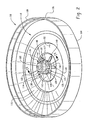
- FIG. 1 there is shown a cross section of a conventional alkaline electrochemical cell 90.
- the cell components are the container 10, first electrode 50 positioned adjacent the interior surface of container 10, separator 20 contacting the interior surface 56 of first electrode 50, second electrode 60 disposed within the cavity defined by separator 20 and closure assembly 70 secured to container 10.
- Container 10 has an open end 12, a closed end 14 and a sidewall 16 therebetween.
- the closed end 14, sidewall 16 and closure assembly 70 define a cavity in which the cell's electrodes are housed.
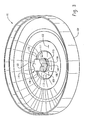
- seal body 100 is a generally disc shaped component with a first surface 102, a second surface 104 and an edge 106 that defines the perimeter of the seal.
- First surface 102 may be referred to herein as the top surface.
- Second surface 104 may be referred to herein as the bottom surface.
- the edge 106 includes an upstanding wall 108.
- central region 110 of seal body 100 Inwardly disposed from the wall is central region 110 of seal body 100.
- the central region comprises a flexible diaphragm 112 that abuts ventable interface 126.
- the ventable interface contacts protrusion 114 that projects perpendicularly from the center of the seal body's top surface.
- the protrusion is also known herein as a hub.
- Located between wall 108 and flexible diaphragm 112 is a nonventing portion 116 of central region 110.
- the nonventing portion is thicker than flexible diaphragm 112 that surrounds hub 114.
- Protrusion 114 in Fig. 2 can be generally described as comprising three distinct sections even though all sections of the hub, like the seal itself, are formed as a single component when the seal is manufactured.
- the portion of hub 114 that abuts ventable interface 126 is known herein as proximal section 115.
- the outside diameter of the proximal section is constant throughout the height of the proximal section.
- the top of the proximal section appears to abut the hub's venting section 117.
- the maximum outside diameter of venting section 117 is equal to or slightly smaller than the outside diameter of proximal section 115.
- Venting section 117 includes one or more indentations 128, 130, 132 and 138 that function as pressure relief indentations for the seal body.
- the indentations are arcuate shaped.
- the ratio of the width of the indentation to the depth of indentation should be greater than 1:1 and less than 6:1.
- the ratio of width to depth is greater than 2:1 and less than 4:1. More preferably, the ratio is about 3:1.
- the indentations could be shaped as rectangles, semicircles or ovals.
- Extensions 140 separate the indentations from one another.
- the top of the venting section forms a first shoulder 142 that abuts the bottom of the hub's third section that is known herein as the distal section 119.
- the outside diameter of distal section 119 is less than the outside diameter of venting section 117 which is equal to or less than the outside diameter of proximal section 115.
- the outer surface of distal section 119 is free of the indentations that characterize venting section 117.
- the end of distal section 119 forms a second shoulder 120 at the end of hub 114.
- the interior surfaces of distal section 119, venting section 117 and proximal section 115 define an opening 122 through seal body 100.
- Proximal section 115 forms ventable interface 126 with flexible diaphragm 112.
- the interface is designed to rupture when the cell's internal pressure reaches a predetermined value.
- ventable interface 126 will tear quickly when the seal body vents.
- proximal section 115 and flexible diaphragm 112 form an arc shaped ventable interface 126 having a uniform thickness around the proximal section.
- the arc is achieved by having a washer shaped proximal section abutting a thin ventable interface.
- the arc is at least 180°, more preferably 270° and most preferably a circle.
- the height of the proximal section must be selected to insure that the one or more indentations in the venting section do not interfere with the tearing at interface 126.
- the venting section's key function is to provide one or more indentations which serve as pressure relief paths for the entrapped gas as it is released from within the cell. While the length, width and height of the indentation can be altered to accommodate factors such as moldability of the seal body, indentations with a width to depth ratio of approximately 3:1 are preferred. An arcuate shaped indentation is particularly preferred because the arc is easy to incorporate into the mold used to form the seal body. Furthermore, an arcuate shaped indentation facilitates uniform manufacturing of the seal body. The height of the indentation must be sufficient to allow the gas to escape to the cell's environment.
- distal section 119 The principle function of distal section 119 is to provide a leakproof interface between current collector 276 and inner cover 150 (see Fig. 5).
- the interface between the collector and the inner cover must be able to stop electrolyte from leaving the cell by creeping along the surface of the collector. This is accomplished by using a collector with an outside diameter larger than the inside diameter of opening 122 in seal body 100 so that an interference fit is established between the collector and seal body.
- the thickness of the distal section between these two parts must be consistent. Consequently, the one or more indentations that characterize the venting section must terminate below the distal section so that the indentation does not interfere with the compression of the seal body in distal section 119 of protrusion 114.
- one or more ribs 148 may be incorporated into the top surface of flexible diaphragm 112.
- One end of each rib 148 abuts the outer surface of proximal section 115.
- Each rib is integrally formed in top surface 102 of seal body 100 and is located along a line radiating from the center of seal body 100 toward the perimeter of the seal body.
- An end of each rib 148 that abuts the proximal section of the hub is approximately located between the indentations in venting section 117 of hub 114.
- Ribs 148 are intended to prevent flexible diaphragm 112 from resealing against the interior surface of inner cover 150. Since the ribs prevent a portion of the torn flexible diaphragm from moving upward and blocking the escape route of the gas that is trapped within the cell, the ruptured seal body does not reseal and allow the cell to become pressurized once again.
- Seal body 101 is disc shaped and formed as a single component having a first surface 102, a second surface 104 and a perimeter 106.
- Flexible diaphragm 112 is formed between the first surface and the second surface.
- Protrusion 114 projects from first surface 102 and abuts flexible diaphragm 112 at ventable interface 126.
- Protrusion 114 comprises proximal section 115 and venting section 117.
- the surface of proximal section 115 is free of any grooves, indentations or channels.
- the surface of venting section 117 comprises at least one indentation.
- the hub may have several indentations 128, 130, 132 and 138.
- the number of indentations may be varied to accommodate differences in the seal's physical parameters such as: outer diameter of the seal's hub; elasticity of the seal material at elevated temperature; and pressure at which the seal is designed to vent.
- the hub has two, four or six indentations. Between any two adjacent indentations is an outwardly bowed portion 140. The outwardly bowed portion separates the individual indentations, also referred to herein as relief paths, from one another.
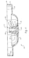
- Fig. 4 shows a cross section of the seal of Fig. 2.
- Protrusion 114 comprises proximal section 115, venting section 117 and distal section 119.
- Proximal section 115 abuts flexible diaphragm 112 at ventable interface 126.
- the surface of proximal section 115 is free of any grooves or indentations.
- Venting section 117 comprises indentation 130 and outwardly bowed portions 140 (not shown).
- Distal section 119 which is concentrically aligned with proximal section 115 and venting section 117, adjoins venting section 117.
- the free end of protrusion 114 terminates at shoulder 120.
- Opening 122 located in the center of the seal body, defines a passage between top surface 102 and bottom surface 104.
- Perimeter 106 is defined by wall 108.
- Ledge 152 abuts wall 108.
- Rib 148 extends from the surface of flexible diaphragm 112.
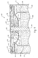
- FIG. 5 Shown in Fig. 5 is a partial cross sectional view of an electrochemical cell 200 of this invention.
- the cell includes container 210 having an open end 212. Disposed within the container are first electrode 250, second electrode 260, separator 220 and a quantity of an aqueous alkaline electrolyte.
- Closure assembly 270 is secured to the open end of the container.
- the assembly comprises seal body 100 that includes proximal section 115 which adjoins flexible diaphragm 112 at ventable interface 126, venting section 117 that abuts proximal section 115 and includes indentations 130 and 132, and distal section 119 which is concentric with and adjoins venting section 117.
- the closure assembly also includes a centrally located current collector 276 that protrudes through opening 122 in seal body 100 and inner cover 150.
- the current collector is an elongated rod made of an electrically conductive material such as brass. One end of the collector contacts second electrode 260 and the opposite end of the collector protrudes through top surface 102 of seal body 100 and contacts one of the cell's terminal covers 158.
- Inner cover 150 is located above top surface 102 of seal body 100.
- the perimeter of cover 150 contacts seal ledge 152.
- the center of cover 150 defines an opening 154.
- the inside diameter of cover opening 154 is smaller than the outer diameter of the hub's venting section 117 and greater than the outer diameter of the hub's distal section 119.
- the outside diameter of collector 276, the inside diameter of opening 112 and the thickness of distal section 119 are selected so that after collector 276 has been inserted into opening 122 in seal body 100, a portion of distal section 119 is forced outwardly against cover 150 by collector 276 thereby imparting tangential tension on the seal body's distal section and creating an interference fit between collector 276 and distal section 119 as well as distal section 119 and cover 150.
- the purpose of creating the interference fit is to prevent the escape of electrolyte along the interface of collector 276 and hub 114. Since distal section 119 must be uniformly compressed between collector 276 and inner cover 150, the pressure relief indentations located in the hub's venting section 117 cannot extend into the distal section.
- a second opening 156 in cover 150 allows gases that vent through a rupture in the seal to escape from the space defined by the top surface 102 of the seal body and cover 150.
- An opening 160 in terminal cover 158 allows gases that have passed through opening 156 to move beyond the terminal cover into the cell's external environment.
- Terminal cover 158 positioned above closure assembly 270, makes electrical contact with current collector 276.
- First electrode 250 contacts the inside surface of container 250 and defines a centrally located cavity.
- First electrode 250 is a mixture of manganese dioxide, graphite and an aqueous solution containing potassium hydroxide.
- the electrode is formed by disposing a quantity of the mixture into the open ended container and then using a ram to mold the mixture into a solid tubular shape that defines a cavity which is concentric with the sidewall of the container.
- First electrode 250 has a ledge 252 and an interior surface 256.
- the cathode may be formed by preforming a plurality of rings from the mixture comprising manganese dioxide and then inserting the rings into the container to form the tubularly shaped first electrode.
- Second electrode 260 is a homogenous mixture of an aqueous alkaline electrolyte, zinc powder, and a gelling agent such as crosslinked polyacrylic acid.
- the aqueous alkaline electrolyte comprises an alkaline metal hydroxide such as potassium hydroxide, sodium hydroxide, or mixtures thereof. Potassium hydroxide is preferred.
- the gelling agent suitable for use in a cell of this invention can be a crosslinked polyacrylic acid, such as Carbopol 940®, which is available from B. F. Goodrich, Performance Materials Division, Cleveland, Ohio, USA. Carboxymethyylcellulose, polyacrylamide and sodium polyacrylate are examples of other gelling agents that are suitable for use in an alkaline electrolyte solution.
- the zinc powder may be pure zinc or an alloy comprising an appropriate amount of one or more of the metals selected from the group consisting of indium, lead, bismuth, lithium, calcium and aluminum.
- a suitable anode mixture contains 67 weight percent zinc powder, 0.50 weight percent gelling agent and 32.5 weight percent alkaline electrolyte having 40 weight percent potassium hydroxide.
- the quantity of zinc can range from 63 percent by weight to 70 percent by weight of the anode.
- Other components such as gassing inhibitors, organic or inorganic anticorrosive agents, binders or surfactants may be optionally added to the ingredients listed above.
- gassing inhibitors or anticorrosive agents can include indium salts (such as indium hydroxide), perfluoroalkyl ammonium salts, alkali metal sulfides, etc.
- surfactants can include polyethylene oxide, polyethylene alkylethers, perfluoroalkyl compounds, and the like.
- the second electrode may be manufactured by combining the ingredients described above into a ribbon blender or drum mixer and then working the mixture into a wet slurry.
- Electrolyte suitable for use in a cell of this invention is a thirty-seven percent by weight aqueous solution of potassium hydroxide.
- the electrolyte may be incorporated into the cell by disposing a quantity of the fluid electrolyte into the cavity defined by the first electrode.
- the electrolyte may also be introduced into the cell by allowing the gelling medium to absorb an aqueous solution of potassium hydroxide during the process used to manufacture the second electrode.
- the method used to incorporate electrolyte into the cell is not critical provided the electrolyte is in contact with the first electrode 250, second electrode 260 and separator 220.
- Separator 220 is a coiled film of nonwoven fibers.
- the separator is disposed about the interior surface 256 of first electrode 250.
- One of the separator's functions is to provide a barrier at the interface of the first and second electrodes.
- the barrier must be electrically insulating and ionically permeable.
Landscapes
- Chemical & Material Sciences (AREA)
- Chemical Kinetics & Catalysis (AREA)
- Electrochemistry (AREA)
- General Chemical & Material Sciences (AREA)
- Gas Exhaust Devices For Batteries (AREA)
- Sealing Battery Cases Or Jackets (AREA)
Applications Claiming Priority (3)
| Application Number | Priority Date | Filing Date | Title |
|---|---|---|---|
| US10/079,678 US6737188B2 (en) | 2002-02-20 | 2002-02-20 | Seal for an electrochemical cell |
| US79678 | 2002-02-20 | ||
| PCT/US2003/002614 WO2003073532A2 (en) | 2002-02-20 | 2003-01-29 | Seal for an electrochemical cell |
Publications (2)
| Publication Number | Publication Date |
|---|---|
| EP1476910A2 EP1476910A2 (en) | 2004-11-17 |
| EP1476910B1 true EP1476910B1 (en) | 2005-11-30 |
Family
ID=27733075
Family Applications (1)
| Application Number | Title | Priority Date | Filing Date |
|---|---|---|---|
| EP03707584A Expired - Lifetime EP1476910B1 (en) | 2002-02-20 | 2003-01-29 | Seal for an electrochemical cell |
Country Status (8)
| Country | Link |
|---|---|
| US (1) | US6737188B2 (enExample) |
| EP (1) | EP1476910B1 (enExample) |
| JP (1) | JP4515770B2 (enExample) |
| CN (1) | CN1310350C (enExample) |
| AT (1) | ATE311668T1 (enExample) |
| AU (1) | AU2003209423A1 (enExample) |
| DE (1) | DE60302553T2 (enExample) |
| WO (1) | WO2003073532A2 (enExample) |
Families Citing this family (7)
| Publication number | Priority date | Publication date | Assignee | Title |
|---|---|---|---|---|
| EP1678769B1 (en) * | 2003-10-28 | 2011-09-28 | Johnson Controls Technology Company | Battery system with improved heat dissipation |
| US7579105B2 (en) * | 2005-02-18 | 2009-08-25 | The Gillette Company | End cap assembly and vent for high power cells |
| JP2008533682A (ja) * | 2005-03-14 | 2008-08-21 | ジョンソン コントロールズ テクノロジー カンパニー | リチウム電池システム |
| ES2275419B1 (es) * | 2005-07-27 | 2008-04-16 | Celaya Emparanza Y Galdos, S.A. Cegasa | "dispositivo de seguridad en cierres estancos de pilas electroquimicas". |
| KR100804703B1 (ko) * | 2006-11-01 | 2008-02-18 | 삼성에스디아이 주식회사 | 전기 출력량 측정장치 및 이를 포함하는 연료 전지용 스택 |
| US20080166626A1 (en) * | 2007-01-05 | 2008-07-10 | Yoppolo Robert A | End cap seal assembly for an electrochemical cell |
| US20090226805A1 (en) * | 2008-03-07 | 2009-09-10 | Robert Yoppolo | Battery |
Family Cites Families (7)
| Publication number | Priority date | Publication date | Assignee | Title |
|---|---|---|---|---|
| JPS61133552A (ja) * | 1984-12-03 | 1986-06-20 | Fuji Elelctrochem Co Ltd | 防爆形電池用封口ガスケツト |
| JP2543325Y2 (ja) * | 1991-01-14 | 1997-08-06 | ソニー株式会社 | 電 池 |
| US5925478A (en) * | 1997-06-25 | 1999-07-20 | Eveready Battery Company, Inc. | V-shaped gasket for galvanic cells |
| JP3948120B2 (ja) * | 1998-06-15 | 2007-07-25 | ソニー株式会社 | ガスケットとガスケットの成形方法及びこのガスケットを用いた円筒形アルカリ電池 |
| JP2000195478A (ja) * | 1998-12-24 | 2000-07-14 | Toshiba Battery Co Ltd | 円筒形アルカリ電池 |
| US6270919B1 (en) * | 1999-04-27 | 2001-08-07 | Eveready Battery Company, Inc. | Electrochemical cell having low profile seal assembly with anti-resealing vent |
| US6312850B1 (en) * | 1999-09-14 | 2001-11-06 | Eveready Battery Company, Inc. | Current collector and seal assembly for electrochemical cell |
-
2002
- 2002-02-20 US US10/079,678 patent/US6737188B2/en not_active Expired - Lifetime
-
2003
- 2003-01-29 JP JP2003572111A patent/JP4515770B2/ja not_active Expired - Fee Related
- 2003-01-29 AT AT03707584T patent/ATE311668T1/de not_active IP Right Cessation
- 2003-01-29 EP EP03707584A patent/EP1476910B1/en not_active Expired - Lifetime
- 2003-01-29 AU AU2003209423A patent/AU2003209423A1/en not_active Abandoned
- 2003-01-29 CN CNB038040867A patent/CN1310350C/zh not_active Expired - Fee Related
- 2003-01-29 WO PCT/US2003/002614 patent/WO2003073532A2/en not_active Ceased
- 2003-01-29 DE DE60302553T patent/DE60302553T2/de not_active Expired - Lifetime
Also Published As
| Publication number | Publication date |
|---|---|
| JP2005518651A (ja) | 2005-06-23 |
| CN1310350C (zh) | 2007-04-11 |
| DE60302553D1 (de) | 2006-01-05 |
| WO2003073532A2 (en) | 2003-09-04 |
| US20030157398A1 (en) | 2003-08-21 |
| US6737188B2 (en) | 2004-05-18 |
| AU2003209423A8 (en) | 2003-09-09 |
| EP1476910A2 (en) | 2004-11-17 |
| AU2003209423A1 (en) | 2003-09-09 |
| ATE311668T1 (de) | 2005-12-15 |
| WO2003073532A3 (en) | 2003-12-18 |
| JP4515770B2 (ja) | 2010-08-04 |
| DE60302553T2 (de) | 2006-08-10 |
| CN1633720A (zh) | 2005-06-29 |
Similar Documents
| Publication | Publication Date | Title |
|---|---|---|
| US7704632B2 (en) | Electrochemical cell having a vent assembly with a rupturable seal member | |
| US7491464B2 (en) | Alkaline cell with flat housing | |
| US7094494B2 (en) | Alkaline cell with flat housing | |
| EP1456894B1 (en) | Electrochemical cell having venting current collector and seal assembly | |
| JP4820748B2 (ja) | 電気化学電池用のエンドキャップ封止組立体 | |
| US6733917B1 (en) | Seal for pressurized container with a rupturable seal | |
| US7294429B2 (en) | Alkaline cell with flat housing | |
| EP1476910B1 (en) | Seal for an electrochemical cell | |
| US7351495B2 (en) | Method of adding electrolyte to a gap between the cathode and separator of an alkaline cell | |
| EP1716607A2 (en) | Alkaline cell with flat housing | |
| HK1069483B (en) | Electrochemical cell having venting current collector and seal assembly |
Legal Events
| Date | Code | Title | Description |
|---|---|---|---|
| PUAI | Public reference made under article 153(3) epc to a published international application that has entered the european phase |
Free format text: ORIGINAL CODE: 0009012 |
|
| 17P | Request for examination filed |
Effective date: 20040803 |
|
| AK | Designated contracting states |
Kind code of ref document: A2 Designated state(s): AT BE BG CH CY CZ DE DK EE ES FI FR GB GR HU IE IT LI LU MC NL PT SE SI SK TR |
|
| AX | Request for extension of the european patent |
Extension state: AL LT LV MK RO |
|
| GRAP | Despatch of communication of intention to grant a patent |
Free format text: ORIGINAL CODE: EPIDOSNIGR1 |
|
| GRAS | Grant fee paid |
Free format text: ORIGINAL CODE: EPIDOSNIGR3 |
|
| GRAA | (expected) grant |
Free format text: ORIGINAL CODE: 0009210 |
|
| AK | Designated contracting states |
Kind code of ref document: B1 Designated state(s): AT BE BG CH CY CZ DE DK EE ES FI FR GB GR HU IE IT LI LU MC NL PT SE SI SK TR |
|
| PG25 | Lapsed in a contracting state [announced via postgrant information from national office to epo] |
Ref country code: IT Free format text: LAPSE BECAUSE OF FAILURE TO SUBMIT A TRANSLATION OF THE DESCRIPTION OR TO PAY THE FEE WITHIN THE PRESCRIBED TIME-LIMIT;WARNING: LAPSES OF ITALIAN PATENTS WITH EFFECTIVE DATE BEFORE 2007 MAY HAVE OCCURRED AT ANY TIME BEFORE 2007. THE CORRECT EFFECTIVE DATE MAY BE DIFFERENT FROM THE ONE RECORDED. Effective date: 20051130 Ref country code: CZ Free format text: LAPSE BECAUSE OF FAILURE TO SUBMIT A TRANSLATION OF THE DESCRIPTION OR TO PAY THE FEE WITHIN THE PRESCRIBED TIME-LIMIT Effective date: 20051130 Ref country code: NL Free format text: LAPSE BECAUSE OF FAILURE TO SUBMIT A TRANSLATION OF THE DESCRIPTION OR TO PAY THE FEE WITHIN THE PRESCRIBED TIME-LIMIT Effective date: 20051130 Ref country code: AT Free format text: LAPSE BECAUSE OF FAILURE TO SUBMIT A TRANSLATION OF THE DESCRIPTION OR TO PAY THE FEE WITHIN THE PRESCRIBED TIME-LIMIT Effective date: 20051130 Ref country code: FI Free format text: LAPSE BECAUSE OF FAILURE TO SUBMIT A TRANSLATION OF THE DESCRIPTION OR TO PAY THE FEE WITHIN THE PRESCRIBED TIME-LIMIT Effective date: 20051130 Ref country code: SK Free format text: LAPSE BECAUSE OF FAILURE TO SUBMIT A TRANSLATION OF THE DESCRIPTION OR TO PAY THE FEE WITHIN THE PRESCRIBED TIME-LIMIT Effective date: 20051130 Ref country code: SI Free format text: LAPSE BECAUSE OF FAILURE TO SUBMIT A TRANSLATION OF THE DESCRIPTION OR TO PAY THE FEE WITHIN THE PRESCRIBED TIME-LIMIT Effective date: 20051130 |
|
| REG | Reference to a national code |
Ref country code: CH Ref legal event code: EP Ref country code: GB Ref legal event code: FG4D |
|
| REG | Reference to a national code |
Ref country code: IE Ref legal event code: FG4D |
|
| REF | Corresponds to: |
Ref document number: 60302553 Country of ref document: DE Date of ref document: 20060105 Kind code of ref document: P |
|
| PG25 | Lapsed in a contracting state [announced via postgrant information from national office to epo] |
Ref country code: IE Free format text: LAPSE BECAUSE OF NON-PAYMENT OF DUE FEES Effective date: 20060130 |
|
| PG25 | Lapsed in a contracting state [announced via postgrant information from national office to epo] |
Ref country code: LU Free format text: LAPSE BECAUSE OF NON-PAYMENT OF DUE FEES Effective date: 20060131 Ref country code: MC Free format text: LAPSE BECAUSE OF NON-PAYMENT OF DUE FEES Effective date: 20060131 |
|
| PG25 | Lapsed in a contracting state [announced via postgrant information from national office to epo] |
Ref country code: SE Free format text: LAPSE BECAUSE OF FAILURE TO SUBMIT A TRANSLATION OF THE DESCRIPTION OR TO PAY THE FEE WITHIN THE PRESCRIBED TIME-LIMIT Effective date: 20060228 Ref country code: GR Free format text: LAPSE BECAUSE OF FAILURE TO SUBMIT A TRANSLATION OF THE DESCRIPTION OR TO PAY THE FEE WITHIN THE PRESCRIBED TIME-LIMIT Effective date: 20060228 Ref country code: DK Free format text: LAPSE BECAUSE OF FAILURE TO SUBMIT A TRANSLATION OF THE DESCRIPTION OR TO PAY THE FEE WITHIN THE PRESCRIBED TIME-LIMIT Effective date: 20060228 Ref country code: BG Free format text: LAPSE BECAUSE OF FAILURE TO SUBMIT A TRANSLATION OF THE DESCRIPTION OR TO PAY THE FEE WITHIN THE PRESCRIBED TIME-LIMIT Effective date: 20060228 |
|
| PG25 | Lapsed in a contracting state [announced via postgrant information from national office to epo] |
Ref country code: ES Free format text: LAPSE BECAUSE OF FAILURE TO SUBMIT A TRANSLATION OF THE DESCRIPTION OR TO PAY THE FEE WITHIN THE PRESCRIBED TIME-LIMIT Effective date: 20060313 |
|
| REG | Reference to a national code |
Ref country code: CH Ref legal event code: NV Representative=s name: A. BRAUN, BRAUN, HERITIER, ESCHMANN AG PATENTANWAE |
|
| PG25 | Lapsed in a contracting state [announced via postgrant information from national office to epo] |
Ref country code: PT Free format text: LAPSE BECAUSE OF FAILURE TO SUBMIT A TRANSLATION OF THE DESCRIPTION OR TO PAY THE FEE WITHIN THE PRESCRIBED TIME-LIMIT Effective date: 20060502 |
|
| NLV1 | Nl: lapsed or annulled due to failure to fulfill the requirements of art. 29p and 29m of the patents act | ||
| PG25 | Lapsed in a contracting state [announced via postgrant information from national office to epo] |
Ref country code: HU Free format text: LAPSE BECAUSE OF FAILURE TO SUBMIT A TRANSLATION OF THE DESCRIPTION OR TO PAY THE FEE WITHIN THE PRESCRIBED TIME-LIMIT Effective date: 20060601 |
|
| ET | Fr: translation filed | ||
| PLBE | No opposition filed within time limit |
Free format text: ORIGINAL CODE: 0009261 |
|
| STAA | Information on the status of an ep patent application or granted ep patent |
Free format text: STATUS: NO OPPOSITION FILED WITHIN TIME LIMIT |
|
| REG | Reference to a national code |
Ref country code: IE Ref legal event code: MM4A |
|
| 26N | No opposition filed |
Effective date: 20060831 |
|
| GBPC | Gb: european patent ceased through non-payment of renewal fee |
Effective date: 20070129 |
|
| PG25 | Lapsed in a contracting state [announced via postgrant information from national office to epo] |
Ref country code: GB Free format text: LAPSE BECAUSE OF NON-PAYMENT OF DUE FEES Effective date: 20070129 |
|
| PGFP | Annual fee paid to national office [announced via postgrant information from national office to epo] |
Ref country code: CH Payment date: 20080130 Year of fee payment: 6 |
|
| REG | Reference to a national code |
Ref country code: CH Ref legal event code: PFA Owner name: EVEREADY BATTERY COMPANY, INC. Free format text: EVEREADY BATTERY COMPANY, INC.#25225 DETROIT ROAD, P O BOX 450777#WESTLAKE, OHIO 44145-0616 (US) -TRANSFER TO- EVEREADY BATTERY COMPANY, INC.#25225 DETROIT ROAD, P O BOX 450777#WESTLAKE, OHIO 44145-0616 (US) |
|
| PG25 | Lapsed in a contracting state [announced via postgrant information from national office to epo] |
Ref country code: EE Free format text: LAPSE BECAUSE OF FAILURE TO SUBMIT A TRANSLATION OF THE DESCRIPTION OR TO PAY THE FEE WITHIN THE PRESCRIBED TIME-LIMIT Effective date: 20051130 |
|
| PG25 | Lapsed in a contracting state [announced via postgrant information from national office to epo] |
Ref country code: TR Free format text: LAPSE BECAUSE OF FAILURE TO SUBMIT A TRANSLATION OF THE DESCRIPTION OR TO PAY THE FEE WITHIN THE PRESCRIBED TIME-LIMIT Effective date: 20051130 |
|
| PG25 | Lapsed in a contracting state [announced via postgrant information from national office to epo] |
Ref country code: CY Free format text: LAPSE BECAUSE OF FAILURE TO SUBMIT A TRANSLATION OF THE DESCRIPTION OR TO PAY THE FEE WITHIN THE PRESCRIBED TIME-LIMIT Effective date: 20051130 |
|
| REG | Reference to a national code |
Ref country code: CH Ref legal event code: PL |
|
| PG25 | Lapsed in a contracting state [announced via postgrant information from national office to epo] |
Ref country code: LI Free format text: LAPSE BECAUSE OF NON-PAYMENT OF DUE FEES Effective date: 20090131 Ref country code: CH Free format text: LAPSE BECAUSE OF NON-PAYMENT OF DUE FEES Effective date: 20090131 |
|
| REG | Reference to a national code |
Ref country code: FR Ref legal event code: ST Effective date: 20091030 |
|
| PG25 | Lapsed in a contracting state [announced via postgrant information from national office to epo] |
Ref country code: FR Free format text: LAPSE BECAUSE OF NON-PAYMENT OF DUE FEES Effective date: 20090202 |
|
| REG | Reference to a national code |
Ref country code: DE Ref legal event code: R082 Ref document number: 60302553 Country of ref document: DE Representative=s name: VON KREISLER SELTING WERNER - PARTNERSCHAFT VO, DE Ref country code: DE Ref legal event code: R081 Ref document number: 60302553 Country of ref document: DE Owner name: ENERGIZER BRANDS, LLC (N.D.GES.D. STAATES DELA, US Free format text: FORMER OWNER: EVEREADY BATTERY CO., INC., WESTLAKE, OHIO, US Ref country code: DE Ref legal event code: R082 Ref document number: 60302553 Country of ref document: DE Representative=s name: DOMPATENT VON KREISLER SELTING WERNER - PARTNE, DE |
|
| PGFP | Annual fee paid to national office [announced via postgrant information from national office to epo] |
Ref country code: FR Payment date: 20080117 Year of fee payment: 6 |
|
| PGFP | Annual fee paid to national office [announced via postgrant information from national office to epo] |
Ref country code: BE Payment date: 20181217 Year of fee payment: 17 |
|
| PGFP | Annual fee paid to national office [announced via postgrant information from national office to epo] |
Ref country code: DE Payment date: 20190115 Year of fee payment: 17 |
|
| REG | Reference to a national code |
Ref country code: DE Ref legal event code: R119 Ref document number: 60302553 Country of ref document: DE |
|
| REG | Reference to a national code |
Ref country code: BE Ref legal event code: MM Effective date: 20200131 |
|
| PG25 | Lapsed in a contracting state [announced via postgrant information from national office to epo] |
Ref country code: DE Free format text: LAPSE BECAUSE OF NON-PAYMENT OF DUE FEES Effective date: 20200801 |
|
| PG25 | Lapsed in a contracting state [announced via postgrant information from national office to epo] |
Ref country code: BE Free format text: LAPSE BECAUSE OF NON-PAYMENT OF DUE FEES Effective date: 20200131 |