EP1475464A1 - Method for producing an optical fluoride crystal - Google Patents
Method for producing an optical fluoride crystal Download PDFInfo
- Publication number
- EP1475464A1 EP1475464A1 EP03291088A EP03291088A EP1475464A1 EP 1475464 A1 EP1475464 A1 EP 1475464A1 EP 03291088 A EP03291088 A EP 03291088A EP 03291088 A EP03291088 A EP 03291088A EP 1475464 A1 EP1475464 A1 EP 1475464A1
- Authority
- EP
- European Patent Office
- Prior art keywords
- zone
- crystal
- temperature
- crucible
- raw material
- Prior art date
- Legal status (The legal status is an assumption and is not a legal conclusion. Google has not performed a legal analysis and makes no representation as to the accuracy of the status listed.)
- Withdrawn
Links
- 239000013078 crystal Substances 0.000 title claims abstract description 87
- KRHYYFGTRYWZRS-UHFFFAOYSA-M Fluoride anion Chemical compound [F-] KRHYYFGTRYWZRS-UHFFFAOYSA-M 0.000 title claims abstract description 17
- 230000003287 optical effect Effects 0.000 title claims abstract description 15
- 238000004519 manufacturing process Methods 0.000 title claims abstract description 8
- 239000002994 raw material Substances 0.000 claims abstract description 18
- 238000000034 method Methods 0.000 claims description 32
- 238000001816 cooling Methods 0.000 claims description 28
- 238000010438 heat treatment Methods 0.000 claims description 17
- WUKWITHWXAAZEY-UHFFFAOYSA-L calcium difluoride Chemical compound [F-].[F-].[Ca+2] WUKWITHWXAAZEY-UHFFFAOYSA-L 0.000 claims description 6
- 229910001634 calcium fluoride Inorganic materials 0.000 claims description 6
- 238000002844 melting Methods 0.000 claims description 6
- 230000008018 melting Effects 0.000 claims description 6
- 229910001637 strontium fluoride Inorganic materials 0.000 claims description 3
- FVRNDBHWWSPNOM-UHFFFAOYSA-L strontium fluoride Chemical compound [F-].[F-].[Sr+2] FVRNDBHWWSPNOM-UHFFFAOYSA-L 0.000 claims description 3
- 229910001632 barium fluoride Inorganic materials 0.000 claims description 2
- PQXKHYXIUOZZFA-UHFFFAOYSA-M lithium fluoride Inorganic materials [Li+].[F-] PQXKHYXIUOZZFA-UHFFFAOYSA-M 0.000 claims description 2
- 229910001635 magnesium fluoride Inorganic materials 0.000 claims description 2
- 239000000203 mixture Substances 0.000 claims description 2
- PUZPDOWCWNUUKD-UHFFFAOYSA-M sodium fluoride Inorganic materials [F-].[Na+] PUZPDOWCWNUUKD-UHFFFAOYSA-M 0.000 claims description 2
- 239000012768 molten material Substances 0.000 description 11
- 238000000137 annealing Methods 0.000 description 6
- 239000000463 material Substances 0.000 description 6
- 238000002425 crystallisation Methods 0.000 description 5
- 230000008025 crystallization Effects 0.000 description 5
- 238000009413 insulation Methods 0.000 description 3
- 239000000155 melt Substances 0.000 description 3
- XKRFYHLGVUSROY-UHFFFAOYSA-N Argon Chemical compound [Ar] XKRFYHLGVUSROY-UHFFFAOYSA-N 0.000 description 2
- 230000008901 benefit Effects 0.000 description 2
- 230000005540 biological transmission Effects 0.000 description 2
- 230000015572 biosynthetic process Effects 0.000 description 2
- 230000007547 defect Effects 0.000 description 2
- 230000001419 dependent effect Effects 0.000 description 2
- 239000011810 insulating material Substances 0.000 description 2
- 238000001393 microlithography Methods 0.000 description 2
- 239000000843 powder Substances 0.000 description 2
- 230000007704 transition Effects 0.000 description 2
- 238000010521 absorption reaction Methods 0.000 description 1
- 229910052786 argon Inorganic materials 0.000 description 1
- 239000002178 crystalline material Substances 0.000 description 1
- 238000002474 experimental method Methods 0.000 description 1
- 239000001307 helium Substances 0.000 description 1
- 229910052734 helium Inorganic materials 0.000 description 1
- SWQJXJOGLNCZEY-UHFFFAOYSA-N helium atom Chemical compound [He] SWQJXJOGLNCZEY-UHFFFAOYSA-N 0.000 description 1
- 238000005286 illumination Methods 0.000 description 1
- 230000002045 lasting effect Effects 0.000 description 1
- 239000012254 powdered material Substances 0.000 description 1
- 238000001228 spectrum Methods 0.000 description 1
- XLYOFNOQVPJJNP-UHFFFAOYSA-N water Substances O XLYOFNOQVPJJNP-UHFFFAOYSA-N 0.000 description 1
Images



Classifications
-
- C—CHEMISTRY; METALLURGY
- C30—CRYSTAL GROWTH
- C30B—SINGLE-CRYSTAL GROWTH; UNIDIRECTIONAL SOLIDIFICATION OF EUTECTIC MATERIAL OR UNIDIRECTIONAL DEMIXING OF EUTECTOID MATERIAL; REFINING BY ZONE-MELTING OF MATERIAL; PRODUCTION OF A HOMOGENEOUS POLYCRYSTALLINE MATERIAL WITH DEFINED STRUCTURE; SINGLE CRYSTALS OR HOMOGENEOUS POLYCRYSTALLINE MATERIAL WITH DEFINED STRUCTURE; AFTER-TREATMENT OF SINGLE CRYSTALS OR A HOMOGENEOUS POLYCRYSTALLINE MATERIAL WITH DEFINED STRUCTURE; APPARATUS THEREFOR
- C30B11/00—Single-crystal growth by normal freezing or freezing under temperature gradient, e.g. Bridgman-Stockbarger method
-
- C—CHEMISTRY; METALLURGY
- C30—CRYSTAL GROWTH
- C30B—SINGLE-CRYSTAL GROWTH; UNIDIRECTIONAL SOLIDIFICATION OF EUTECTIC MATERIAL OR UNIDIRECTIONAL DEMIXING OF EUTECTOID MATERIAL; REFINING BY ZONE-MELTING OF MATERIAL; PRODUCTION OF A HOMOGENEOUS POLYCRYSTALLINE MATERIAL WITH DEFINED STRUCTURE; SINGLE CRYSTALS OR HOMOGENEOUS POLYCRYSTALLINE MATERIAL WITH DEFINED STRUCTURE; AFTER-TREATMENT OF SINGLE CRYSTALS OR A HOMOGENEOUS POLYCRYSTALLINE MATERIAL WITH DEFINED STRUCTURE; APPARATUS THEREFOR
- C30B29/00—Single crystals or homogeneous polycrystalline material with defined structure characterised by the material or by their shape
- C30B29/10—Inorganic compounds or compositions
- C30B29/12—Halides
Definitions
- the invention relates to optical crystals and to a method for producing a fluoride crystal suitable for use in the vacuum ultraviolet region.
- Fluoride crystals are useful materials because of their low-wavelength absorption edges. Properly grown crystals have a high transmission in the vacuum ultraviolet region of the electromagnetic spectrum; that is, at wavelengths below 230 nm.
- the main demand for such fluoride crystals comes from the microlithography industry. These fluoride crystals can be used for manufacturing optics and optical components for use in excimer lasers, and also optical components for use in projection and illumination systems.
- the resolution of the microlithography process is such that optical materials used in exposure systems must be of integrity. Typically, birefringence should be less than 3 nm/cm and optical homogeneity should be less than 3 ppm. To obtain crystals of such quality, a great deal of attention must be paid to the growth process.
- a fluoride raw material F is loaded into a crucible C, which is disposed inside a hot zone HZ of a vertical furnace 1.
- the hot zone HZ is then heated to a temperature sufficient to melt the fluoride raw material F.
- the crucible C is slowly lowered from the hot zone HZ to a cold zone CZ, as shown in Figure 1B.
- the molten material F goes through a zone of thermal gradient.
- the temperature transition inside the molten material F creates a crystal front CF.
- the crystal front CF propagates inside the crucible C, within the material F, as long as the crucible C is caused to move in a downward direction.
- the melt is generally exposed to sharp localized cooling as it is translated from the hot zone to the cold zone.
- Such sharp localized cooling generates thermal strain in the crystal, which results in unacceptably elevated values in birefringence and optical homogeneity.
- an annealing process typically follows the growth process described above. In the annealing process the crystal is first heated to a temperature below its melting point. The crystal is then held at this temperature for a given period of time in a homogeneous temperature field before being slowly cooled to room temperature. This allows the thermal strain in the crystal to be dissipated.
- the annealing process described above is a very long process, lasting several days.
- the process of re-heating the crystal and holding it at a high temperature for a long time can result in defects in the crystal, which in turn can lead to lower transmission in the crystal.
- a process which does not require annealing, or greatly shortens the time required for the annealing process is desirable.
- the invention is directed to a method for producing an optical fluoride crystal in which a crucible containing a molten raw material is translated (moved) from a first zone through a thermally-graded zone into a second zone to thereby form an optical fluoride crystal, and controlling a temperature of at least one of the first zone and the second zone such that an effective radial temperature gradient at a point in the thermally-graded zone where the crystal is formed does not exceed 5 °C/cm.
- the invention is directed to a method for producing an optical fluoride crystal in which a crucible containing a molten crystal raw material is translated from a first zone through a thermally-graded zone into a second zone to form a crystal, and controlling a temperature of at least one of the first zone and the second zone such that an effective radial and axial temperature gradients at a point in the thermally-graded zone where the crystal is formed does not exceed 5 °C/cm and 10 °C/cm, respectively.
- Figures 1A and 1B illustrate a process for forming a crystal.
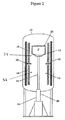
- Figure 2 illustrates a furnace for growing a crystal.
- Figure 3 show a stack of crucibles within a furnace.
- Figure 4 shows a crystal being formed as the crucible of Figure 2 is translated through a thermal gradient zone.
- a method consistent with the principles of the invention minimizes rapid localized cooling of a crystal melt during the crystal growth process.
- the invention works by carefully controlling the shape of the crystallization front at the growth interface while simultaneously providing a uniform temperature field in the cold zone without abruptly cooling the crystals. Crystals grown under such conditions can have a birefringence less than 2 nm/cm and optical homogeneity less than 2 ppm. Therefore, further heat treatment to relieve thermal strain can be eliminated.
- Figures 1A illustrates a crucible containing a fluoride raw material in a furnace hot zone where the material is melted.
- Figure 1B illustrates the crucible partially translated into the cold zone. Within the crucible a crystal from has grown and molten material remains above the crystal front. As the crucible continues to be translated into the cold zone the crystal continues to grow until the crucible is completely in the cold zone and all the molten material within the crucible has crystallized.
- FIG. 2 shows an environment suitable for practice of the invention, including a vertical furnace 10 having an upper zone 12 and a lower zone 14.
- a heating element 16 is provided in the upper zone 12 to maintain an appropriate temperature in the upper zone 12.
- a heating element 18 is also provided in the lower zone 14 to maintain an appropriate temperature in the lower zone 14.
- the temperature of upper and lower zones 12 and 14 can be monitored by the use of temperature measuring elements 34 and 36, for example, thermocouples 34 and 36. Elements 34 and 36 can simply monitor the temperature in each zone, or they can be linked to a controller to control the temperature of each zone.
- Insulating material 19 is provided around the heating elements 16, 18 to contain heat in the furnace 10. In an alternate embodiment, additional insulation may be provided in the lower zone 14 to allow an appropriate temperature to be maintained within the lower zone 14.
- This insulation can be used in addition to or in lieu of the heating element 18.
- multiple heaters can be provided in either or both of the upper zone 12 and lower zone 14 to maintain the required temperatures in the zones 12, 14.
- the heating element 18 in the lower zone 14 can be controlled independently of the heating element 16 in the upper zone 12.
- the diaphragm 20 partially isolates the upper zone 12 from the lower zone 14, creating a thermal gradient zone between the upper zone 12 and the lower zone 14.
- the vertical temperature gradient across the diaphragm 20 is dependent on the geometry of the furnace 10; that is, the length of the heating elements 16, 18, the vertical distance between the heating elements 16, 18, the insulation in the furnace 10, and the temperatures in the upper and lower zones 12, 14. It should be noted that the heating element 18 does not have to extend across the entire length of the lower zone 14; that is, a short heating element can be used in the lower zone 14, just below the diaphragm 20. Provision can be made for cold water to circulate inside the diaphragm 20 to obtain a temperature gradient of more sizable intensity.
- a crucible 22 is disposed inside the upper zone 12.
- the crucible 22 contains a crystal raw material or melt F.
- the crystal raw material F is a feedstock for preparing fluoride crystals, for example single crystals of CaF 2 , BaF 2 , SrF 2 , LiF, MgF 2 , or NaF; or for preparing crystals containing a mixture of these crystals.
- CaF 2 powder and SrF 2 powder are mixed together, melted and solidified to form a CaSrF 2 single crystal.
- the crucible 22 may be a single unit or may be divided into several vertically stacked bowls (elements 23 in Figure 3). Typically, the stacked bowls (elements 23 in Figure 3) would communicate through openings in the center of bottoms, except for the botton bowl which has no opening. The opening are approxmately 3-4 mm in diameter.
- Each bowl is filled to capacity and stack is placed in the furnace. As the charge melts and densifies, it flows downwards filling the bowl below it.
- the bottom bowl contains a seed crystal to initiate crystal formation. Crystallization occurs from the bottom bowl upward and as the material in each bowl completes its crystallization it provides, via the opening between it and the bowl above it, the seed for crystallizing the material inthe bowl bowl above it.
- a series of stacked bowls one is able to grow a plurality of crystalline disks rather than a single, large cylindrical crystal as is usually carried out in the art.
- a charging device or reservoir may be provided to fill the stacked bowls with the molten material.
- this reservoir is filled with powdered material which melts, densifies and flows into the top bowl through an opening in the reservoir bottom. Flow continues through the bowls as described above until each bowl is filled.
- a lift mechanism 24 is coupled to the crucible 22 to lower the crucible 22 from the upper zone 12, through the diaphragm 20, into the lower zone 14.
- the lift mechanism 24 could be a rod 26 coupled to a hydraulic or pneumatic actuator 28.
- the actuator 28 may be controlled as necessary to translate the crucible 22 inside the furnace 10.
- the invention is based in part on the discovery that radial temperature gradients can result in deformation of the crystal growth interface.
- a highly concave or convex interface can result in spurious grain formation and high birefringence due to nonuniformity in cooling the interface.
- the radial temperature gradient at the crystal growth interface is no greater than 5 °C/cm.
- sufficient axial, or vertical, thermal gradient at the diaphragm 20 is needed to grow the crystal.
- the axial thermal gradient should not be so high that it causes rapid localized cooling in the molten material F.
- the axial temperature gradient at the diaphragm 20, that is, within the thermal gradient zone is no greater than 10 °C/cm.
- the furnace 10 is hermetically sealed and the required atmosphere is created inside the upper zone 12.
- This atmosphere can be a vacuum, an inert atmosphere (helium, argon or other inert atmosphere) or a fluorinating atmosphere.
- the upper zone 12 is then heated to a temperature sufficient to melt the content of the crucible 22 or maintain the content of the crucible 22 in a molten condition.
- the temperature is typically set at 1500 °C or higher.
- the crucible 22 with the molten material is slowly translated from the upper zone 12, through the diaphragm 20, into the lower zone 14.
- the lower zone 14 is maintained at a temperature lower than the temperature in the upper zone 12 so that there is a temperature gradient across the diaphragm 20.
- the molten material F goes through the zone of thermal gradient. As shown in Figure 4, on passing through this zone, the temperature transition inside the molten material F creates a crystal front CF.
- the crystal front CF propagates inside the crucible 22, within the molten material F, as long as the crucible 22 continues to move in a downward direction into the lower zone 14.
- the effective axial temperature gradient at the crystal growth interface 30, that is, the interface between the molten material F and the crystal front CF, does not exceed 10 °C/cm.
- the effective radial temperature at the crystal growth interface 30 does not exceed 5 °C/cm. Control of both axial and radial temperature gradients at the crystal growth interface and uniform temperature in the lower zone 14 can be achieved by the heating element 18 and/or having a highly insulated lower zone 14.
- the temperature of the lower zone 14 is preferably held at a temperature greater than 550 °C below the melting temperature of the crystal raw material but not more than 100 °C below the melting temperature of the crystal raw material.
- the crystal can be cooled directly to room temperature without re-heating.
- the cooling rate of the crystal should be less than 15 °C/h (°C/hour).
- the cooling rates should be in the range of 1-10 °C/hour and the time for cooling to room temperature would be in the range of 10-30 days.
- the exact time for cooling will be dependent on the rate at which cooling occurs. For example, at a cooling rate of approximately 3°C/hour, the time will be approximately 17 days.
- the cooling rate can also be divided into several independent steps. For example, at temperatures above 700 °C, the cooling rate should preferably be in the range of 1-4 °C/hour, and more preferably no greater than 2.5-3.0 °C/h. At temperatures below 700 °C and above 550 °C, the cooling rate should preferably be in the range of 1-6 °C, and more preferably no greater than 5 °C/h. At temperatures below 550 °C and above 400 °C, the cooling rate should generally not exceed 10 °C/h. It is efficient to increase the cooling rate when the temperature is below 400°C to greater than 10 °C/h. This cooling schedule ensures that the crystal is not cooled too rapidly.
- a 300-mm diameter CaF 2 crystal disk was grown in a furnace equipped with independently controlled heaters in the upper and lower zones. The zones were separated by a diaphragm. The temperature of the upper heater was set at 1500 °C. The temperature of the lower heater was set at 1250 °C. The calcium fluoride raw material was loaded into a crucible and melted in the upper zone by ramping the heater setpoints over a period of 4-6 days. The crucible was then lowered at 2.5 mm/hr through the diaphragm region, where crystallization occurred, and then into the lower zone. Once in the lower zone, the crystalline material was directly cooled to room temperature in 17 days at a rate of 3 °C/hour over a 17 day period.
- the furnace used in this experiment employs a heater that is 2-3 time the length of the crystal in order to provide the correct thermal environment for cooling the crystals.
- This heater provides a thermal environment with a ⁇ 10 °C/cm axial thermal gradient and a ⁇ 5 °C/cm radial thermal gradient.
- the upper and lower heater temperatures are maintained within approximately 100 °C of each other in order to achieve the desired thermal gradients.
- the heater temperatures can be as much a 250 °C apart, with the provision that within 1-2 days after the start of the cooling/crystallization cycle the heater temperatures are brought to within 100 °C of each other and maintained within this difference during the process until lower temperatures (less than 550 °C) are reached.
- the cooling rate for example to approximately 10 °C/hour, at temperature below 550 °C. No further heat treatment steps were performed.
- the crystals obtained from this process have less than 1 nm/cm birefringence and less than 2 ppm optical homogeneity.
Landscapes
- Chemical & Material Sciences (AREA)
- Engineering & Computer Science (AREA)
- Crystallography & Structural Chemistry (AREA)
- Materials Engineering (AREA)
- Metallurgy (AREA)
- Organic Chemistry (AREA)
- Inorganic Chemistry (AREA)
- Crystals, And After-Treatments Of Crystals (AREA)
Abstract
A method for producing an optical fluoride crystal includes translating a crucible
containing a molten crystal raw material from a first zone, through a thermally-graded zone,
into a second zone to form a crystal and controlling a temperature of at least one of the first
zone and the second zone such that an effective radial temperature gradient at a point in the
thermally-graded zone where the crystal is formed does not exceed 5 °C/cm.
Description
- The invention relates to optical crystals and to a method for producing a fluoride crystal suitable for use in the vacuum ultraviolet region.
- Fluoride crystals are useful materials because of their low-wavelength absorption edges. Properly grown crystals have a high transmission in the vacuum ultraviolet region of the electromagnetic spectrum; that is, at wavelengths below 230 nm. The main demand for such fluoride crystals comes from the microlithography industry. These fluoride crystals can be used for manufacturing optics and optical components for use in excimer lasers, and also optical components for use in projection and illumination systems. The resolution of the microlithography process is such that optical materials used in exposure systems must be of impeccable quality. Typically, birefringence should be less than 3 nm/cm and optical homogeneity should be less than 3 ppm. To obtain crystals of such quality, a great deal of attention must be paid to the growth process.
- Single fluoride crystals are commonly grown using the Stockbarger-Bridgeman process. This process is described with reference to Figures 1A and 1B. In Figure 1A, a fluoride raw material F is loaded into a crucible C, which is disposed inside a hot zone HZ of a
vertical furnace 1. The hot zone HZ is then heated to a temperature sufficient to melt the fluoride raw material F. After melting the fluoride raw material F, the crucible C is slowly lowered from the hot zone HZ to a cold zone CZ, as shown in Figure 1B. As the crucible C passes from the hot zone HZ to the cold zone CZ, the molten material F goes through a zone of thermal gradient. On passing through this zone, the temperature transition inside the molten material F creates a crystal front CF. The crystal front CF propagates inside the crucible C, within the material F, as long as the crucible C is caused to move in a downward direction. - In the technique described above, the melt is generally exposed to sharp localized cooling as it is translated from the hot zone to the cold zone. Such sharp localized cooling generates thermal strain in the crystal, which results in unacceptably elevated values in birefringence and optical homogeneity. To reduce thermal strain in the crystal an annealing process typically follows the growth process described above. In the annealing process the crystal is first heated to a temperature below its melting point. The crystal is then held at this temperature for a given period of time in a homogeneous temperature field before being slowly cooled to room temperature. This allows the thermal strain in the crystal to be dissipated.
- However, the annealing process described above is a very long process, lasting several days. In addition, the process of re-heating the crystal and holding it at a high temperature for a long time can result in defects in the crystal, which in turn can lead to lower transmission in the crystal. In view of the length of time for conventional annealing and the economic losses incurred when crystals develop defects, a process which does not require annealing, or greatly shortens the time required for the annealing process, is desirable.
- In one aspect, the invention is directed to a method for producing an optical fluoride crystal in which a crucible containing a molten raw material is translated (moved) from a first zone through a thermally-graded zone into a second zone to thereby form an optical fluoride crystal, and controlling a temperature of at least one of the first zone and the second zone such that an effective radial temperature gradient at a point in the thermally-graded zone where the crystal is formed does not exceed 5 °C/cm.
- In another aspect, the invention is directed to a method for producing an optical fluoride crystal in which a crucible containing a molten crystal raw material is translated from a first zone through a thermally-graded zone into a second zone to form a crystal, and controlling a temperature of at least one of the first zone and the second zone such that an effective radial and axial temperature gradients at a point in the thermally-graded zone where the crystal is formed does not exceed 5 °C/cm and 10 °C/cm, respectively.
- Other features and advantages of the invention will be apparent from the following description and the appended claims.
- Figures 1A and 1B illustrate a process for forming a crystal.
- Figure 2 illustrates a furnace for growing a crystal.
- Figure 3 show a stack of crucibles within a furnace.
- Figure 4 shows a crystal being formed as the crucible of Figure 2 is translated through a thermal gradient zone.
- A method consistent with the principles of the invention minimizes rapid localized cooling of a crystal melt during the crystal growth process. The invention works by carefully controlling the shape of the crystallization front at the growth interface while simultaneously providing a uniform temperature field in the cold zone without abruptly cooling the crystals. Crystals grown under such conditions can have a birefringence less than 2 nm/cm and optical homogeneity less than 2 ppm. Therefore, further heat treatment to relieve thermal strain can be eliminated.
- Figures 1A illustrates a crucible containing a fluoride raw material in a furnace hot zone where the material is melted. Figure 1B illustrates the crucible partially translated into the cold zone. Within the crucible a crystal from has grown and molten material remains above the crystal front. As the crucible continues to be translated into the cold zone the crystal continues to grow until the crucible is completely in the cold zone and all the molten material within the crucible has crystallized.
- Figure 2 shows an environment suitable for practice of the invention, including a
vertical furnace 10 having anupper zone 12 and alower zone 14. Aheating element 16 is provided in theupper zone 12 to maintain an appropriate temperature in theupper zone 12. Aheating element 18 is also provided in thelower zone 14 to maintain an appropriate temperature in thelower zone 14. The temperature of upper andlower zones temperature measuring elements thermocouples Elements material 19 is provided around theheating elements furnace 10. In an alternate embodiment, additional insulation may be provided in thelower zone 14 to allow an appropriate temperature to be maintained within thelower zone 14. This insulation can be used in addition to or in lieu of theheating element 18. In alternate embodiments, multiple heaters can be provided in either or both of theupper zone 12 andlower zone 14 to maintain the required temperatures in thezones heating element 18 in thelower zone 14 can be controlled independently of theheating element 16 in theupper zone 12. - A diaphragm or
baffle 20, made of an insulating material, is disposed between theupper zone 12 and thelower zone 14, between theheating elements diaphragm 20 partially isolates theupper zone 12 from thelower zone 14, creating a thermal gradient zone between theupper zone 12 and thelower zone 14. The vertical temperature gradient across thediaphragm 20 is dependent on the geometry of thefurnace 10; that is, the length of theheating elements heating elements furnace 10, and the temperatures in the upper andlower zones heating element 18 does not have to extend across the entire length of thelower zone 14; that is, a short heating element can be used in thelower zone 14, just below thediaphragm 20. Provision can be made for cold water to circulate inside thediaphragm 20 to obtain a temperature gradient of more sizable intensity. - In the method of the invention, a
crucible 22 is disposed inside theupper zone 12. Thecrucible 22 contains a crystal raw material or melt F. In one embodiment, the crystal raw material F is a feedstock for preparing fluoride crystals, for example single crystals of CaF2, BaF2, SrF2, LiF, MgF2, or NaF; or for preparing crystals containing a mixture of these crystals. For example, CaF2 powder and SrF2 powder are mixed together, melted and solidified to form a CaSrF2 single crystal. - The
crucible 22 may be a single unit or may be divided into several vertically stacked bowls (elements 23 in Figure 3). Typically, the stacked bowls (elements 23 in Figure 3) would communicate through openings in the center of bottoms, except for the botton bowl which has no opening. The opening are approxmately 3-4 mm in diameter. Each bowl is filled to capacity and stack is placed in the furnace. As the charge melts and densifies, it flows downwards filling the bowl below it. The bottom bowl contains a seed crystal to initiate crystal formation. Crystallization occurs from the bottom bowl upward and as the material in each bowl completes its crystallization it provides, via the opening between it and the bowl above it, the seed for crystallizing the material inthe bowl bowl above it. By using a series of stacked bowls one is able to grow a plurality of crystalline disks rather than a single, large cylindrical crystal as is usually carried out in the art. - In an alternate embodiment, a charging device or reservoir (not shown) may be provided to fill the stacked bowls with the molten material. Typically, this reservoir is filled with powdered material which melts, densifies and flows into the top bowl through an opening in the reservoir bottom. Flow continues through the bowls as described above until each bowl is filled.
- A
lift mechanism 24 is coupled to thecrucible 22 to lower thecrucible 22 from theupper zone 12, through thediaphragm 20, into thelower zone 14. As an example, thelift mechanism 24 could be arod 26 coupled to a hydraulic orpneumatic actuator 28. Theactuator 28 may be controlled as necessary to translate thecrucible 22 inside thefurnace 10. - The invention is based in part on the discovery that radial temperature gradients can result in deformation of the crystal growth interface. A highly concave or convex interface can result in spurious grain formation and high birefringence due to nonuniformity in cooling the interface. Preferably, the radial temperature gradient at the crystal growth interface is no greater than 5 °C/cm. Also, sufficient axial, or vertical, thermal gradient at the
diaphragm 20 is needed to grow the crystal. However, the axial thermal gradient should not be so high that it causes rapid localized cooling in the molten material F. Preferably, the axial temperature gradient at thediaphragm 20, that is, within the thermal gradient zone, is no greater than 10 °C/cm. - In operation, the
furnace 10 is hermetically sealed and the required atmosphere is created inside theupper zone 12. This atmosphere can be a vacuum, an inert atmosphere (helium, argon or other inert atmosphere) or a fluorinating atmosphere. Theupper zone 12 is then heated to a temperature sufficient to melt the content of thecrucible 22 or maintain the content of thecrucible 22 in a molten condition. For example, for CaF2, the temperature is typically set at 1500 °C or higher. Thecrucible 22 with the molten material is slowly translated from theupper zone 12, through thediaphragm 20, into thelower zone 14. Thelower zone 14 is maintained at a temperature lower than the temperature in theupper zone 12 so that there is a temperature gradient across thediaphragm 20. As thecrucible 22 passes through thediaphragm 20, the molten material F goes through the zone of thermal gradient. As shown in Figure 4, on passing through this zone, the temperature transition inside the molten material F creates a crystal front CF. The crystal front CF propagates inside thecrucible 22, within the molten material F, as long as thecrucible 22 continues to move in a downward direction into thelower zone 14. - As the
crucible 22 passes through the temperature gradient zone, defined at thediaphragm 20, it is important that the content of thecrucible 22 does not experience a rapid drop in temperature. Preferably, the effective axial temperature gradient at thecrystal growth interface 30, that is, the interface between the molten material F and the crystal front CF, does not exceed 10 °C/cm. Preferably, the effective radial temperature at thecrystal growth interface 30 does not exceed 5 °C/cm. Control of both axial and radial temperature gradients at the crystal growth interface and uniform temperature in thelower zone 14 can be achieved by theheating element 18 and/or having a highly insulatedlower zone 14. To ensure a sufficient axial temperature gradient at the crystal growth interface, the temperature of thelower zone 14 is preferably held at a temperature greater than 550 °C below the melting temperature of the crystal raw material but not more than 100 °C below the melting temperature of the crystal raw material. - When the
entire crucible mass 22 has moved into the effective area of thelower zone 14, the crystal can be cooled directly to room temperature without re-heating. The cooling rate of the crystal should be less than 15 °C/h (°C/hour). Preferably, the cooling rates should be in the range of 1-10 °C/hour and the time for cooling to room temperature would be in the range of 10-30 days. The exact time for cooling will be dependent on the rate at which cooling occurs. For example, at a cooling rate of approximately 3°C/hour, the time will be approximately 17 days. - The cooling rate can also be divided into several independent steps. For example, at temperatures above 700 °C, the cooling rate should preferably be in the range of 1-4 °C/hour, and more preferably no greater than 2.5-3.0 °C/h. At temperatures below 700 °C and above 550 °C, the cooling rate should preferably be in the range of 1-6 °C, and more preferably no greater than 5 °C/h. At temperatures below 550 °C and above 400 °C, the cooling rate should generally not exceed 10 °C/h. It is efficient to increase the cooling rate when the temperature is below 400°C to greater than 10 °C/h. This cooling schedule ensures that the crystal is not cooled too rapidly.
- The following example is presented for illustration purposes and is not intended to limit the invention as otherwise described herein.
- A 300-mm diameter CaF2 crystal disk was grown in a furnace equipped with independently controlled heaters in the upper and lower zones. The zones were separated by a diaphragm. The temperature of the upper heater was set at 1500 °C. The temperature of the lower heater was set at 1250 °C. The calcium fluoride raw material was loaded into a crucible and melted in the upper zone by ramping the heater setpoints over a period of 4-6 days. The crucible was then lowered at 2.5 mm/hr through the diaphragm region, where crystallization occurred, and then into the lower zone. Once in the lower zone, the crystalline material was directly cooled to room temperature in 17 days at a rate of 3 °C/hour over a 17 day period. The furnace used in this experiment employs a heater that is 2-3 time the length of the crystal in order to provide the correct thermal environment for cooling the crystals. This heater provides a thermal environment with a <10 °C/cm axial thermal gradient and a < 5 °C/cm radial thermal gradient. During cooling the upper and lower heater temperatures are maintained within approximately 100 °C of each other in order to achieve the desired thermal gradients. However, as an option, during the first part of the cooling, the heater temperatures can be as much a 250 °C apart, with the provision that within 1-2 days after the start of the cooling/crystallization cycle the heater temperatures are brought to within 100 °C of each other and maintained within this difference during the process until lower temperatures (less than 550 °C) are reached. It is also noted that optionally one can increase the cooling rate, for example to approximately 10 °C/hour, at temperature below 550 °C. No further heat treatment steps were performed. The crystals obtained from this process have less than 1 nm/cm birefringence and less than 2 ppm optical homogeneity.
- While the invention has been described with respect to a limited number of embodiments, those skilled in the art, having benefit of this disclosure, will appreciate that other embodiments can be devised which do not depart from the scope of the invention as disclosed herein. Accordingly, the scope of the invention should be limited only by the attached claims.
Claims (15)
- A method for producing an optical fluoride crystal, comprising:translating a crucible containing a molten crystal raw material from a first zone, through a thermally-graded zone, into a second zone to form a crystal; andcontrolling a temperature of at least one of the first zone and second zone such that an effective radial temperature gradient at a point in the thermally-graded zone where the crystal is formed does not exceed 5 °C/cm.
- The method of claim 1, further comprising controlling a temperature difference between the first zone and the second zone such that an effective axial temperature gradient in the thermally-graded zone does not exceed 10 °C/cm.
- The method of claim 1 or claim 2, wherein controlling the temperature or the temperature difference comprises controlling a heating element in the second zone.
- The method of claim 1 or claim 2, wherein controlling the temperature or the temperature difference between the first zone and the second zone comprises heavily insulating the second zone.
- The method of any one of the preceding claims, wherein the first zone is maintained at a temperature above a melting point of the crystal raw material.
- The method of any one of claims 1-5, wherein the temperature in the second zone is maintained in a range from 100 to 550 °C below a melting point of the crystal raw material.
- The method of any one of the preceding claims, further comprising cooling the crystal in the second zone.
- The method of any one of claims 1-6 further comprising cooling the crystal in the second zone at a rate less than 15 °C/h.
- The method of claim 7, wherein a cooling rate of the crystal from a temperature above 700 °C is no greater than 2.5 °C/h.
- The method of claim 7, wherein a cooling rate of the crystal from a temperature above 550 °C is no greater than 5 °C/h.
- The method of claim 7, wherein a cooling rate of the crystal from a temperature above 400 °C is no greater than 10 °C/h.
- The method of any one of the preceding claims, wherein a translation rate of the crucible is 2.5 mm/hr.
- The method of any one of the preceding claims, wherein the crystal raw material comprises one selected from the group consisting of CaF2, BaF2, SrF2, LiF, MgF2, NaF, and mixtures thereof.
- The method of any one of the preceding claims, wherein the crucible comprises a stack of bowls, each of which contains a portion of the molten crystal raw material.
- A method for producing an optical fluoride crystal, comprising:translating a crucible containing a molten crystal raw material from a first zone, through a thermally-graded zone, into a second zone to form a crystal; andcontrolling a temperature of at least one of the first zone and the second zone such that an effective radial and axial temperature gradient at a point in the thermally-graded zone where the crystal is formed does not exceed 5 °C/cm and 10 °C/cm, respectively.
Priority Applications (4)
| Application Number | Priority Date | Filing Date | Title |
|---|---|---|---|
| EP03291088A EP1475464A1 (en) | 2003-05-06 | 2003-05-06 | Method for producing an optical fluoride crystal |
| US10/809,154 US20040221793A1 (en) | 2003-05-06 | 2004-03-25 | Method for producing an optical fluoride crystal without annealing |
| JP2004135395A JP2004339053A (en) | 2003-05-06 | 2004-04-30 | Method for producing optical fluoride crystal |
| DE102004022053A DE102004022053A1 (en) | 2003-05-06 | 2004-05-05 | Process for producing an optical fluoride crystal |
Applications Claiming Priority (1)
| Application Number | Priority Date | Filing Date | Title |
|---|---|---|---|
| EP03291088A EP1475464A1 (en) | 2003-05-06 | 2003-05-06 | Method for producing an optical fluoride crystal |
Publications (1)
| Publication Number | Publication Date |
|---|---|
| EP1475464A1 true EP1475464A1 (en) | 2004-11-10 |
Family
ID=32981982
Family Applications (1)
| Application Number | Title | Priority Date | Filing Date |
|---|---|---|---|
| EP03291088A Withdrawn EP1475464A1 (en) | 2003-05-06 | 2003-05-06 | Method for producing an optical fluoride crystal |
Country Status (4)
| Country | Link |
|---|---|
| US (1) | US20040221793A1 (en) |
| EP (1) | EP1475464A1 (en) |
| JP (1) | JP2004339053A (en) |
| DE (1) | DE102004022053A1 (en) |
Cited By (3)
| Publication number | Priority date | Publication date | Assignee | Title |
|---|---|---|---|---|
| DE102005010654A1 (en) * | 2005-03-08 | 2006-09-14 | Schott Ag | Production of high-homogeneous, tension-poor and large volume calcium fluoride single crystal e.g. for production of lenses, prisms and optical components for deep ultraviolet photolithography, comprises cooling crystal after its breeding |
| ITRM20090074A1 (en) * | 2009-02-19 | 2010-08-20 | Bove Rafael Dalenz | OVEN WITH THERMAL GRADIENT CONTROLLED FOR WORKING MATERIALS THROUGH THERMAL TREATMENTS SILICONE CRYSTALLIZATION OR OTHER THROUGH POSITIONING OF THE CRUCIBLE POSITION INSIDE THE OVEN |
| RU2400573C1 (en) * | 2009-03-16 | 2010-09-27 | Закрытое акционерное общество (ЗАО) "ИНКРОМ" | Method of producing monocrystals of calcium and barium flourides |
Families Citing this family (2)
| Publication number | Priority date | Publication date | Assignee | Title |
|---|---|---|---|---|
| JP2006315915A (en) * | 2005-05-13 | 2006-11-24 | Canon Inc | Optical member |
| RU200993U1 (en) * | 2020-06-10 | 2020-11-23 | Федеральное государственное бюджетное учреждение науки Институт геологии и минералогии им. В.С. Соболева Сибирского отделения Российской академии наук (Институт геологии и минералогии СО РАН, ИГМ СО РАН) | Thermal unit for growing single crystals |
Citations (10)
| Publication number | Priority date | Publication date | Assignee | Title |
|---|---|---|---|---|
| JPH10251097A (en) * | 1997-03-10 | 1998-09-22 | Nikon Corp | Apparatus and method for producing fluorite single crystal |
| JPH1179880A (en) * | 1997-09-09 | 1999-03-23 | Nikon Corp | Apparatus and method for producing large diameter fluorite |
| EP1022362A2 (en) * | 1999-01-20 | 2000-07-26 | Canon Kabushiki Kaisha | Apparatus and process for producing crystal article |
| WO2001000908A1 (en) * | 1999-06-29 | 2001-01-04 | Acti Optics & Engineering, Inc. | Heater arrangement for crystal growth furnace |
| DE10010484A1 (en) * | 2000-03-03 | 2001-09-13 | Schott Glas | Device for growing large volume single crystals has heating element arranged on side walls of melt crucible to prevent lateral radial heat flow |
| FR2813616A1 (en) * | 2000-09-05 | 2002-03-08 | Sorem | CRYSTALLOGENESIS METHOD AND INSTALLATION FOR ITS IMPLEMENTATION, AND CRYSTALS OBTAINED |
| WO2002031232A1 (en) * | 2000-10-13 | 2002-04-18 | Corning Incorporated | Method and device for producing optical fluoride crystals |
| US20020185057A1 (en) * | 2001-04-16 | 2002-12-12 | Garibin Evgeny A. | Process for growing calcium fluoride monocrystals |
| EP1288348A2 (en) * | 2001-08-31 | 2003-03-05 | Schott Glas | Method to produce fracture resistant calcium fluoride single crystals and applications thereof |
| DE10142652A1 (en) * | 2001-08-31 | 2003-03-27 | Schott Glas | Production of break-proof large size calcium fluoride monocrystals used in the production of lenses for lithography, comprises melting calcium fluoride raw material with the addition of a strengthening material and cooling |
Family Cites Families (3)
| Publication number | Priority date | Publication date | Assignee | Title |
|---|---|---|---|---|
| JP3775776B2 (en) * | 1999-09-20 | 2006-05-17 | ユニオンマテリアル株式会社 | Single crystal manufacturing method |
| FR2799194B1 (en) * | 1999-10-05 | 2001-12-14 | Corning Sa | BALLS OF AN ALKALINE OR POLYCRYSTALLINE ALKALINE EARTH FLUORIDE, THEIR PREPARATION AND THEIR USE FOR PREPARING SINGLE CRYSTALS |
| FR2822853B1 (en) * | 2001-03-29 | 2003-06-27 | Corning Inc | PREPARATION OF (MONO) CRYSTALS |
-
2003
- 2003-05-06 EP EP03291088A patent/EP1475464A1/en not_active Withdrawn
-
2004
- 2004-03-25 US US10/809,154 patent/US20040221793A1/en not_active Abandoned
- 2004-04-30 JP JP2004135395A patent/JP2004339053A/en not_active Withdrawn
- 2004-05-05 DE DE102004022053A patent/DE102004022053A1/en not_active Withdrawn
Patent Citations (10)
| Publication number | Priority date | Publication date | Assignee | Title |
|---|---|---|---|---|
| JPH10251097A (en) * | 1997-03-10 | 1998-09-22 | Nikon Corp | Apparatus and method for producing fluorite single crystal |
| JPH1179880A (en) * | 1997-09-09 | 1999-03-23 | Nikon Corp | Apparatus and method for producing large diameter fluorite |
| EP1022362A2 (en) * | 1999-01-20 | 2000-07-26 | Canon Kabushiki Kaisha | Apparatus and process for producing crystal article |
| WO2001000908A1 (en) * | 1999-06-29 | 2001-01-04 | Acti Optics & Engineering, Inc. | Heater arrangement for crystal growth furnace |
| DE10010484A1 (en) * | 2000-03-03 | 2001-09-13 | Schott Glas | Device for growing large volume single crystals has heating element arranged on side walls of melt crucible to prevent lateral radial heat flow |
| FR2813616A1 (en) * | 2000-09-05 | 2002-03-08 | Sorem | CRYSTALLOGENESIS METHOD AND INSTALLATION FOR ITS IMPLEMENTATION, AND CRYSTALS OBTAINED |
| WO2002031232A1 (en) * | 2000-10-13 | 2002-04-18 | Corning Incorporated | Method and device for producing optical fluoride crystals |
| US20020185057A1 (en) * | 2001-04-16 | 2002-12-12 | Garibin Evgeny A. | Process for growing calcium fluoride monocrystals |
| EP1288348A2 (en) * | 2001-08-31 | 2003-03-05 | Schott Glas | Method to produce fracture resistant calcium fluoride single crystals and applications thereof |
| DE10142652A1 (en) * | 2001-08-31 | 2003-03-27 | Schott Glas | Production of break-proof large size calcium fluoride monocrystals used in the production of lenses for lithography, comprises melting calcium fluoride raw material with the addition of a strengthening material and cooling |
Non-Patent Citations (3)
| Title |
|---|
| PATENT ABSTRACTS OF JAPAN vol. 1998, no. 14 31 December 1998 (1998-12-31) * |
| PATENT ABSTRACTS OF JAPAN vol. 1999, no. 08 30 June 1999 (1999-06-30) * |
| WANG Y ET AL: "Crystal growth of Cr:LiCaAlF6 by Bridgman technique", JOURNAL OF CRYSTAL GROWTH, NORTH-HOLLAND PUBLISHING CO. AMSTERDAM, NL, vol. 167, no. 1, 1 September 1996 (1996-09-01), pages 176 - 179, XP004053534, ISSN: 0022-0248 * |
Cited By (3)
| Publication number | Priority date | Publication date | Assignee | Title |
|---|---|---|---|---|
| DE102005010654A1 (en) * | 2005-03-08 | 2006-09-14 | Schott Ag | Production of high-homogeneous, tension-poor and large volume calcium fluoride single crystal e.g. for production of lenses, prisms and optical components for deep ultraviolet photolithography, comprises cooling crystal after its breeding |
| ITRM20090074A1 (en) * | 2009-02-19 | 2010-08-20 | Bove Rafael Dalenz | OVEN WITH THERMAL GRADIENT CONTROLLED FOR WORKING MATERIALS THROUGH THERMAL TREATMENTS SILICONE CRYSTALLIZATION OR OTHER THROUGH POSITIONING OF THE CRUCIBLE POSITION INSIDE THE OVEN |
| RU2400573C1 (en) * | 2009-03-16 | 2010-09-27 | Закрытое акционерное общество (ЗАО) "ИНКРОМ" | Method of producing monocrystals of calcium and barium flourides |
Also Published As
| Publication number | Publication date |
|---|---|
| DE102004022053A1 (en) | 2004-11-25 |
| JP2004339053A (en) | 2004-12-02 |
| US20040221793A1 (en) | 2004-11-11 |
Similar Documents
| Publication | Publication Date | Title |
|---|---|---|
| US6969502B2 (en) | Method and device for growing large-volume oriented monocrystals | |
| JP5497053B2 (en) | Single crystal germanium crystal growth system, method and substrate | |
| JP3707750B2 (en) | Method for producing calcium fluoride crystals | |
| US20040099205A1 (en) | Method of growing oriented calcium fluoride single crystals | |
| US20030221610A1 (en) | Process for growing calcium fluoride single crystals | |
| JP3006148B2 (en) | Fluorite production equipment with excellent excimer resistance | |
| US6736893B2 (en) | Process for growing calcium fluoride monocrystals | |
| US20040221793A1 (en) | Method for producing an optical fluoride crystal without annealing | |
| JP6969230B2 (en) | Single crystal growth method and single crystal growth device | |
| JP3988217B2 (en) | Large-diameter fluorite manufacturing apparatus and manufacturing method | |
| JP4147595B2 (en) | Method for producing fluorite single crystal | |
| EP0781868A2 (en) | A single crystal growing apparatus | |
| JP3006147B2 (en) | Large diameter fluorite single crystal manufacturing equipment | |
| EP1757716B1 (en) | Method and apparatus for preparing crystal | |
| US7001458B2 (en) | Process for growing of optical fluorite single crystals | |
| KR20070039607A (en) | How to grow single crystals from melt | |
| JP3725280B2 (en) | Fluorite single crystal manufacturing apparatus and manufacturing method | |
| RU2400573C1 (en) | Method of producing monocrystals of calcium and barium flourides | |
| JP3797643B2 (en) | Crystal production equipment | |
| RU2421552C1 (en) | Method of annealing crystals of group iia metal fluorides | |
| JP4228127B2 (en) | Method for producing calcium fluoride crystals | |
| JPH06219884A (en) | Single crystal growth furnace | |
| RU2555901C1 (en) | Method of obtaining scintillation monocrystals based on lanthanum bromide | |
| TWI513865B (en) | Germanium ingots/wafers having low micro-pit density (mpd) as well as systems and methods for manufacturing same | |
| JPH10231194A (en) | Heat treatment apparatus and heat treatment method for fluorite single crystal |
Legal Events
| Date | Code | Title | Description |
|---|---|---|---|
| PUAI | Public reference made under article 153(3) epc to a published international application that has entered the european phase |
Free format text: ORIGINAL CODE: 0009012 |
|
| AK | Designated contracting states |
Kind code of ref document: A1 Designated state(s): AT BE BG CH CY CZ DE DK EE ES FI FR GB GR HU IE IT LI LU MC NL PT RO SE SI SK TR |
|
| AX | Request for extension of the european patent |
Extension state: AL LT LV MK |
|
| AKX | Designation fees paid | ||
| REG | Reference to a national code |
Ref country code: DE Ref legal event code: 8566 |
|
| STAA | Information on the status of an ep patent application or granted ep patent |
Free format text: STATUS: THE APPLICATION IS DEEMED TO BE WITHDRAWN |
|
| 18D | Application deemed to be withdrawn |
Effective date: 20050511 |