EP1475252A1 - Machine for fitting and removing tires and wheel rims for vehicles - Google Patents
Machine for fitting and removing tires and wheel rims for vehicles Download PDFInfo
- Publication number
- EP1475252A1 EP1475252A1 EP04009610A EP04009610A EP1475252A1 EP 1475252 A1 EP1475252 A1 EP 1475252A1 EP 04009610 A EP04009610 A EP 04009610A EP 04009610 A EP04009610 A EP 04009610A EP 1475252 A1 EP1475252 A1 EP 1475252A1
- Authority
- EP
- European Patent Office
- Prior art keywords
- machine according
- tire
- pusher
- rotation axis
- tool
- Prior art date
- Legal status (The legal status is an assumption and is not a legal conclusion. Google has not performed a legal analysis and makes no representation as to the accuracy of the status listed.)
- Granted
Links
Images


Classifications
-
- B—PERFORMING OPERATIONS; TRANSPORTING
- B60—VEHICLES IN GENERAL
- B60C—VEHICLE TYRES; TYRE INFLATION; TYRE CHANGING; CONNECTING VALVES TO INFLATABLE ELASTIC BODIES IN GENERAL; DEVICES OR ARRANGEMENTS RELATED TO TYRES
- B60C25/00—Apparatus or tools adapted for mounting, removing or inspecting tyres
- B60C25/01—Apparatus or tools adapted for mounting, removing or inspecting tyres for removing tyres from or mounting tyres on wheels
- B60C25/05—Machines
- B60C25/132—Machines for removing and mounting tyres
- B60C25/135—Machines for removing and mounting tyres having a tyre support or a tool, movable along wheel axis
- B60C25/138—Machines for removing and mounting tyres having a tyre support or a tool, movable along wheel axis with rotary motion of tool or tyre support
-
- B—PERFORMING OPERATIONS; TRANSPORTING
- B60—VEHICLES IN GENERAL
- B60C—VEHICLE TYRES; TYRE INFLATION; TYRE CHANGING; CONNECTING VALVES TO INFLATABLE ELASTIC BODIES IN GENERAL; DEVICES OR ARRANGEMENTS RELATED TO TYRES
- B60C25/00—Apparatus or tools adapted for mounting, removing or inspecting tyres
- B60C25/01—Apparatus or tools adapted for mounting, removing or inspecting tyres for removing tyres from or mounting tyres on wheels
- B60C25/05—Machines
- B60C25/0518—Horizontal wheel axis in working position
-
- B—PERFORMING OPERATIONS; TRANSPORTING
- B60—VEHICLES IN GENERAL
- B60C—VEHICLE TYRES; TYRE INFLATION; TYRE CHANGING; CONNECTING VALVES TO INFLATABLE ELASTIC BODIES IN GENERAL; DEVICES OR ARRANGEMENTS RELATED TO TYRES
- B60C25/00—Apparatus or tools adapted for mounting, removing or inspecting tyres
- B60C25/01—Apparatus or tools adapted for mounting, removing or inspecting tyres for removing tyres from or mounting tyres on wheels
- B60C25/05—Machines
- B60C25/0563—Tools interacting with the tyre and moved in relation to the tyre during operation
- B60C25/0593—Multi-functional tools for performing at least two operations, e.g. bead breaking and bead seeking
Definitions
- the present invention relates to a machine for fitting and removing tires and wheel rims for vehicles.
- vehicle wheels are generally constituted by a metal rim that is provided peripherally with annular folds between which an elastic tire is keyed; the end portions of said tire, known as beads, each abut against a respective fold of said rim.
- Tires and the associated rims are currently fitted and removed by using machines, known as tire changing machines, which allow to remove the tire from the corresponding rim in order to perform for example maintenance or replacement of the inner tube and subsequently refit the same tire or a replacement tire on the wheel rim.
- tire changing machines which allow to remove the tire from the corresponding rim in order to perform for example maintenance or replacement of the inner tube and subsequently refit the same tire or a replacement tire on the wheel rim.
- tire changing machines of the automatic type which are substantially constituted by a frame for supporting means for coupling and rotating a rim on/from which a tire is to be fitted/removed, and by a working assembly that is provided with a working head for fitting and removing the tire.
- Such working head is generally provided with a tool for fitting the tire on the rim and with a tool for removing the tire.
- the removal tool in particular, is arranged substantially transversely to the longitudinal axis of the working head and is provided with a curved end part that is directed toward' the wheel to be removed during intervention.
- the end part of said tool must be placed in abutment against a side of the tire and pressed against it so as to move the bead of the tire away from the corresponding fold, so as to allow said tool to engage the flap of the tire and move it away from the corresponding rim.
- the removal tool is generally supported by the working head so that it can oscillate, about an axis that is fixed with respect to said head, between a configuration for pushing the side of the tire and engaging the corresponding bead and at least one configuration for moving the tire away from the corresponding rim.
- the aim of the present invention is to eliminate the above-mentioned drawbacks of known tire fitting machines, by providing a machine for fitting and removing tires and wheel rims for vehicles that allows to perform fitting and removal operations simply and rapidly and does not entail onerous expenditures of time if the bead of the tire to be removed is not gripped correctly.
- an object of the present invention is to provide a machine that can be used for a wide range of wheel types regardless of their characteristics (hard or soft rubber) and dimensions.
- Another object of the present invention is to provide a machine that is simple, relatively easy to provide in practice, safe in use, effective in operation, and has a relatively low cost.
- the present machine for fitting and removing tires and wheel rims for vehicles, which comprises a frame for supporting means for coupling and turning a rim, onto/from which a tire is to be fitted/removed, about a rotation axis, and a working assembly that is supported by said frame so that it can move and comprises a working head for fitting and removing said rim and said tire that is associated with first means for translational actuation in a direction that is substantially parallel to said rotation axis, characterized in that said working head is provided with a pusher that is substantially tubular, is arranged substantially transversely to said rotation axis, and is associated with an abutment surface that is associable with a side of said tire, and with at least one tool for removing said tire from said rim, which is associated with second actuation means that are suitable to allow it to move alternately between an inactive configuration, in which it is at least partially accommodated within said pusher, and at least one active
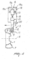
- the reference numeral 1 generally designates a machine for fitting and removing tires and rims of wheels for vehicles.
- the machine 1 comprises a frame 2 for supporting means 3 for coupling and turning a rim C, on/from which it is necessary to fit/remove a tire P, about a rotation axis R, and a working assembly 4 that is supported so that it can move by the frame 2 and is provided with a working head 5 for fitting and removing the rim C and the tire P.
- the head 5 is associated with first actuation means 6 for translational actuation in a direction that is parallel to the rotation axis R, which are constituted by a first actuator 6a that acts in a horizontal direction and is associated with said head.
- the frame 2 is constituted by a footing 2a from which a vertical column 2b rises; the means 3 are associated so that they can slide along said column, and the rotation axis R is arranged horizontally.
- the machine 1 could be provided with a differently structured frame 2 and/or the rotation axis R could be arranged substantially vertically or otherwise inclined.
- the head 5 is provided with a pusher 7 that is substantially tubular, is arranged vertically above the supporting means 3 and transversely to the rotation axis R, and is provided with an abutment surface 8 that is associable with a side of the tire P during removal thereof ( Figure 4).
- the pusher 7 has an open lower end.
- the head 5 further has at least one tool 9 for removing the tire P from the rim C, which is associated with second actuation means 10 that are suitable to allow its movement alternately between an inactive configuration, in which it is contained at least partially inside the pusher 7, and an active configuration, in which it protrudes partially from said pusher ( Figure 11).
- the tool 9 is completely accommodated within the pusher 7 in the inactive configuration ( Figure 10).
- the head 5 is conveniently provided with a supporting tool 11 for supporting the tire P, which acts during removal in order to move said tire away from the rim C ( Figure 7) and during fitting in order to position it on said rim ( Figures 8 and 9).
- the tool 11 is constituted by a plate that is rigidly associated at the lower end of the pusher 7 and cantilevers out on the opposite side of the abutment surface 8.
- the abutment surface 8 is shaped so as to protrude toward the tire P to be removed, so as to form a wedge-shaped element.
- the end 9a of the tool 9 that is directed toward the tire P is hook-shaped and suitable to abut against the inner surface of the bead of the tire.
- the second actuation means 10 comprise guiding means 12 for guiding the tool 9, which are constituted by two pairs of through slots 13 that are formed on the side wall of the pusher 7, preferably monolithically with and at the internal lateral surface of the pusher 7; the slots 13 of each pair are mutually identical and are arranged so as to face each other in a mirror-symmetrical fashion on opposite sides of said pusher.
- Each pair of slots 13 is associated with a respective pivot 14 (in particular 14a, 14b), which is arranged transversely with respect to the tool 9, is associated or connected with said tool, and has each end arranged at, or associated so that it can slide along a corresponding slot 13.
- Each slot 13 is constituted by a plurality of segments or portions that are mutually connected so as to form a broken line path.
- the profiles of the slots 13 are sized so as to guide the tool 9 in a combined (rotary and translational) motion between the inactive configuration and the active configuration.
- the two pivots 14a and 14b are arranged respectively proximate to the centerline of the tool 9 and to the end 9b that lies opposite the hook-shaped end 9a, the end 9b being fork-shaped.
- the second actuation means 10 comprise motion means 15 for producing an alternating rectilinear motion, which are constituted by a second actuator 15a that uses a fluid medium and acts in a vertical direction, and are associated with the tool 9 by means of the interposition of a linkage 16.
- the ends of the linkage 16 are respectively articulated to the lower end of the stem of the second actuator 15a and to the end 9b of the tool 9 at the pivot 14b.
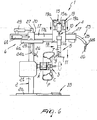
- the frame 2 comprises a guiding element 17, which is constituted by a profiled element that has an I-shaped transverse cross-section, is arranged so that its wings are vertical, and protrudes parallel to the rotation axis R from the upper portion of the column 2b.
- the assembly 4 comprises a slider 18 for supporting the head 5, which is associated so that it can slide along the guiding element 17 and comprises a first portion and a second portion, the first portion being associated with said guiding element, the second portion supporting the head 5 and being associated with the first portion so that it can move.
- the second portion of the slider 18 supports the second actuator 15a.
- the machine 1 further comprises third actuation means 19 for actuating the head 5 with a vertical translational motion, which are constituted by two third actuators 19a that use a fluid medium, act at right angles to the rotation axis R, and are interposed between said portions of the slider 18 and on opposite sides of the second actuator 15a.
- third actuation means 19 for actuating the head 5 with a vertical translational motion which are constituted by two third actuators 19a that use a fluid medium, act at right angles to the rotation axis R, and are interposed between said portions of the slider 18 and on opposite sides of the second actuator 15a.
- the assembly 4 further comprises an additional slider 20, which is associated so that it can slide along the guiding element 17 and is interposed between the slider 18 and the column 2b.
- the first actuation means 6 comprise a first additional fluid-medium actuator 6b, which acts in a direction that is; parallel to the rotation axis R and is interposed between the guiding element 17 and the additional slider 20; the actuation of the first additional actuator 6b produces the translational motion of the additional slider 20 with respect to the guiding element 17 and therefore with respect to the frame 2.
- the first actuator 6a is instead interposed between the additional slider 20 and the slider 18; actuation of the first actuator 6a produces the translational motion of the slider 18 with respect to the additional slider 20.
- the sliders 18 and 20 are associated so that they can slide along a same wing 17a of the guiding element 17.
- the assembly 4 is provided with conventional means 21 for rotating the head 5 about a vertical axis that substantially coincides with the longitudinal axis of said head; such means allow to arrange the tool 11 adjacent to both sides of the tire P ( Figures 10 and 11).
- the rotation means 21 are of the manual type, but alternative embodiments in which said means are actuated automatically are not excluded.
- the rotation means 21 are provided with a device 22 for stopping the rotation of the head 5, which allows to lock said head in two mutually angularly offset configurations.
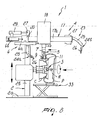
- the assembly 4 comprises means 23 for separating the tire P from the rim C, which perform the operation conventionally known as bead breaking.
- the separation means 23 are constituted by two pushers 24, which are associated so that they can slide along the guiding element 17 on opposite sides of the tire P being treated and are constituted by respective arms 25 for supporting disks 26 that are keyed freely on said arms and can be associated with the sides of the tire P.
- the pusher 24a cooperates with the side of the tire P that is directed toward the column 2b, while the pusher 24b is suitable to cooperate with the side of the tire P that is directed toward the free end of the guiding element 17.
- Each arm 25 is fitted on a corresponding support 27 that is associated so that it can slide along the wing of the guiding element 17 that lies opposite the wing 17a along which the sliders 18 and 20 are arranged.
- the arm 25 of the pusher 24a is rigidly coupled to the corresponding support 27, while the arm 25 of the pusher 24b is associated with the corresponding support 27 so that it can oscillate about an axis that is horizontal and transverse with respect to said element between a configuration that is adjacent to the rim C and a configuration that is spaced from said rim.
- Each arm 25 of the pushers 24a and 24b is associated with an actuator 29, which is suitable to actuate respectively the translational motion along the guiding element 17 and the translational motion along said element combined with rotation.
- the means 3 comprise a flange 30 for supporting the rim C, which is associated with conventional motor means, not shown in the figures, which actuate its rotation about the rotation axis R, a reference rod 31 on which the rim C is fitted, said rod protruding from the center of the flange 30 in a horizontal direction and having a threaded end, and a threaded locking element 32, which couples on the rod 31 and clamps the rim C being processed.
- the means 3 are associated with conventional actuation means, not shown in the figures, which produce their translational motion along the column 2b.
- the machine 1 is further provided with means 33 for lifting and lowering the rim C and the tire P for loading and unloading the means 3, said means not being shown in detail because they are of a conventional type.
- the machine 1 is associated with conventional actuation and control means, not shown in the figures, which allow the operator to actuate its operation and adjust its movements.
- the bead-breaking step allows to separate the beads of the tire P from the corresponding seats on the rim C.
- the pushers 24 move away from the region adjacent to said tire and the pusher 24b moves to a spaced configuration so as not to interfere with the head 5.
- the head 5 is arranged at a suitable distance from the rim C, depending on the dimensional and constructive characteristics of said rim.
- the head 5, with the tool 9 in the inactive configuration, is then moved toward the tire P by means of the actuator 6a so that the abutment surface 8 abuts against the side of the tire P, moving it away from the rim C ( Figure 4) and forming a passage for the tool 9.
- the head 5 is placed proximate to the column 2b, so that the tool 11 grips the corresponding bead of the tire P.
- the opening of the first actuator 6a causes the head 5 to push the tire P, supported by the tool 11, away from the rim C, so as to completely separate said tire ( Figure 7); in this work step, the pusher 24a can cooperate in removing the tire P from the rim C.
Abstract
Description
- The present invention relates to a machine for fitting and removing tires and wheel rims for vehicles.
- It is known that vehicle wheels are generally constituted by a metal rim that is provided peripherally with annular folds between which an elastic tire is keyed; the end portions of said tire, known as beads, each abut against a respective fold of said rim.
- Tires and the associated rims are currently fitted and removed by using machines, known as tire changing machines, which allow to remove the tire from the corresponding rim in order to perform for example maintenance or replacement of the inner tube and subsequently refit the same tire or a replacement tire on the wheel rim.
- For example, tire changing machines of the automatic type are known which are substantially constituted by a frame for supporting means for coupling and rotating a rim on/from which a tire is to be fitted/removed, and by a working assembly that is provided with a working head for fitting and removing the tire.
- Such working head is generally provided with a tool for fitting the tire on the rim and with a tool for removing the tire.
- The removal tool, in particular, is arranged substantially transversely to the longitudinal axis of the working head and is provided with a curved end part that is directed toward' the wheel to be removed during intervention.
- The end part of said tool must be placed in abutment against a side of the tire and pressed against it so as to move the bead of the tire away from the corresponding fold, so as to allow said tool to engage the flap of the tire and move it away from the corresponding rim.
- The removal tool is generally supported by the working head so that it can oscillate, about an axis that is fixed with respect to said head, between a configuration for pushing the side of the tire and engaging the corresponding bead and at least one configuration for moving the tire away from the corresponding rim.
- These tire changing machines are not free from drawbacks, including the fact that if the tire bead is not gripped in an optimum manner, the removal tool can remain jammed between the tire and the rim, requiring manual intervention of the operator, who has to force the tire with one or more levers in order to release the tool.
- Moreover, said machines have limitations that penalize their operating flexibility.
- The aim of the present invention is to eliminate the above-mentioned drawbacks of known tire fitting machines, by providing a machine for fitting and removing tires and wheel rims for vehicles that allows to perform fitting and removal operations simply and rapidly and does not entail onerous expenditures of time if the bead of the tire to be removed is not gripped correctly.
- Within this aim, an object of the present invention is to provide a machine that can be used for a wide range of wheel types regardless of their characteristics (hard or soft rubber) and dimensions.
- Another object of the present invention is to provide a machine that is simple, relatively easy to provide in practice, safe in use, effective in operation, and has a relatively low cost.
- This aim and these and other objects that will become better apparent hereinafter are achieved by the present machine for fitting and removing tires and wheel rims for vehicles, which comprises a frame for supporting means for coupling and turning a rim, onto/from which a tire is to be fitted/removed, about a rotation axis, and a working assembly that is supported by said frame so that it can move and comprises a working head for fitting and removing said rim and said tire that is associated with first means for translational actuation in a direction that is substantially parallel to said rotation axis, characterized in that said working head is provided with a pusher that is substantially tubular, is arranged substantially transversely to said rotation axis, and is associated with an abutment surface that is associable with a side of said tire, and with at least one tool for removing said tire from said rim, which is associated with second actuation means that are suitable to allow it to move alternately between an inactive configuration, in which it is at least partially accommodated within said pusher, and at least one active configuration, in which it protrudes at least partially from said pusher.
- Further characteristics and advantages of the present invention will become better apparent from the following detailed description of a preferred but not exclusive embodiment of a machine for' fitting and removing tires and rims of wheels for vehicles, illustrated by way of nonlimiting example in the accompanying drawings, wherein:
- Figures 1 to 3 are partially sectional schematic side views of the machine for fitting and removing tires and rims of wheels for vehicles according to the invention in successive operating steps during the removal of a tire from the corresponding rim;
- Figures 4 and 5 are partially sectional schematic side views of a portion of the machine of Figure 1 during tire removal;
- Figures 6 and 7 are partially sectional schematic side views of the machine of Figure 1 in further operating steps during tire removal;
- Figures 8 and 9 are two partially sectional schematic side views of the machine shown in the preceding figures, in two successive steps of work during the fitting of the tire on the rim;
- Figure 10 is a schematic sectional view, taken along a longitudinal plane, of the working head of the machine according to the invention with the removal tool in the inactive configuration;
- Figure 11 is a schematic sectional view, taken along a longitudinal plane, of the working head of Figure 10, with the removal tool in the active configuration;
- Figure 12 is a transverse sectional view, taken along the line XII-XII of Figure 11, of the working head;
- Figure 13 is a side view of the removal tool of the machine according to the invention;
- Figure 14 is a plan view of the removal tool of Figure 13.
-
- With reference to the figures, the
reference numeral 1 generally designates a machine for fitting and removing tires and rims of wheels for vehicles. - The
machine 1 comprises aframe 2 for supportingmeans 3 for coupling and turning a rim C, on/from which it is necessary to fit/remove a tire P, about a rotation axis R, and a workingassembly 4 that is supported so that it can move by theframe 2 and is provided with a workinghead 5 for fitting and removing the rim C and the tire P. - The
head 5 is associated with first actuation means 6 for translational actuation in a direction that is parallel to the rotation axis R, which are constituted by a first actuator 6a that acts in a horizontal direction and is associated with said head. - The
frame 2 is constituted by afooting 2a from which a vertical column 2b rises; themeans 3 are associated so that they can slide along said column, and the rotation axis R is arranged horizontally. - As an alternative, the
machine 1 could be provided with a differently structuredframe 2 and/or the rotation axis R could be arranged substantially vertically or otherwise inclined. - The
head 5 is provided with apusher 7 that is substantially tubular, is arranged vertically above the supportingmeans 3 and transversely to the rotation axis R, and is provided with anabutment surface 8 that is associable with a side of the tire P during removal thereof (Figure 4). - The
pusher 7 has an open lower end. - The
head 5 further has at least onetool 9 for removing the tire P from the rim C, which is associated with second actuation means 10 that are suitable to allow its movement alternately between an inactive configuration, in which it is contained at least partially inside thepusher 7, and an active configuration, in which it protrudes partially from said pusher (Figure 11). - Advantageously, in the particular embodiment shown, the
tool 9 is completely accommodated within thepusher 7 in the inactive configuration (Figure 10). - Finally, the
head 5 is conveniently provided with a supportingtool 11 for supporting the tire P, which acts during removal in order to move said tire away from the rim C (Figure 7) and during fitting in order to position it on said rim (Figures 8 and 9). - The
tool 11 is constituted by a plate that is rigidly associated at the lower end of thepusher 7 and cantilevers out on the opposite side of theabutment surface 8. - The
abutment surface 8 is shaped so as to protrude toward the tire P to be removed, so as to form a wedge-shaped element. - The end 9a of the
tool 9 that is directed toward the tire P is hook-shaped and suitable to abut against the inner surface of the bead of the tire. - The second actuation means 10 comprise guiding
means 12 for guiding thetool 9, which are constituted by two pairs of throughslots 13 that are formed on the side wall of thepusher 7, preferably monolithically with and at the internal lateral surface of thepusher 7; theslots 13 of each pair are mutually identical and are arranged so as to face each other in a mirror-symmetrical fashion on opposite sides of said pusher. - Each pair of
slots 13 is associated with a respective pivot 14 (in particular 14a, 14b), which is arranged transversely with respect to thetool 9, is associated or connected with said tool, and has each end arranged at, or associated so that it can slide along acorresponding slot 13. - Each
slot 13 is constituted by a plurality of segments or portions that are mutually connected so as to form a broken line path. - The profiles of the
slots 13 are sized so as to guide thetool 9 in a combined (rotary and translational) motion between the inactive configuration and the active configuration. - The figures show only one
slot 13 for each pair. - The two
pivots tool 9 and to the end 9b that lies opposite the hook-shaped end 9a, the end 9b being fork-shaped. - Moreover, the second actuation means 10 comprise motion means 15 for producing an alternating rectilinear motion, which are constituted by a
second actuator 15a that uses a fluid medium and acts in a vertical direction, and are associated with thetool 9 by means of the interposition of alinkage 16. - The ends of the
linkage 16 are respectively articulated to the lower end of the stem of thesecond actuator 15a and to the end 9b of thetool 9 at thepivot 14b. - The
frame 2 comprises aguiding element 17, which is constituted by a profiled element that has an I-shaped transverse cross-section, is arranged so that its wings are vertical, and protrudes parallel to the rotation axis R from the upper portion of the column 2b. - The
assembly 4 comprises aslider 18 for supporting thehead 5, which is associated so that it can slide along the guidingelement 17 and comprises a first portion and a second portion, the first portion being associated with said guiding element, the second portion supporting thehead 5 and being associated with the first portion so that it can move. - The second portion of the
slider 18 supports thesecond actuator 15a. - The
machine 1 further comprises third actuation means 19 for actuating thehead 5 with a vertical translational motion, which are constituted by twothird actuators 19a that use a fluid medium, act at right angles to the rotation axis R, and are interposed between said portions of theslider 18 and on opposite sides of thesecond actuator 15a. - The
assembly 4 further comprises anadditional slider 20, which is associated so that it can slide along the guidingelement 17 and is interposed between theslider 18 and the column 2b. - Conveniently, the first actuation means 6 comprise a first additional fluid-
medium actuator 6b, which acts in a direction that is; parallel to the rotation axis R and is interposed between the guidingelement 17 and theadditional slider 20; the actuation of the firstadditional actuator 6b produces the translational motion of theadditional slider 20 with respect to the guidingelement 17 and therefore with respect to theframe 2. - The first actuator 6a is instead interposed between the
additional slider 20 and theslider 18; actuation of the first actuator 6a produces the translational motion of theslider 18 with respect to theadditional slider 20. - The
sliders same wing 17a of the guidingelement 17. - The
assembly 4 is provided withconventional means 21 for rotating thehead 5 about a vertical axis that substantially coincides with the longitudinal axis of said head; such means allow to arrange thetool 11 adjacent to both sides of the tire P (Figures 10 and 11). - In the illustrated embodiment, the rotation means 21 are of the manual type, but alternative embodiments in which said means are actuated automatically are not excluded.
- The rotation means 21 are provided with a
device 22 for stopping the rotation of thehead 5, which allows to lock said head in two mutually angularly offset configurations. - Finally, the
assembly 4 comprises means 23 for separating the tire P from the rim C, which perform the operation conventionally known as bead breaking. - The separation means 23 are constituted by two pushers 24, which are associated so that they can slide along the guiding
element 17 on opposite sides of the tire P being treated and are constituted byrespective arms 25 for supportingdisks 26 that are keyed freely on said arms and can be associated with the sides of the tire P. - The
pusher 24a cooperates with the side of the tire P that is directed toward the column 2b, while thepusher 24b is suitable to cooperate with the side of the tire P that is directed toward the free end of the guidingelement 17. - Each
arm 25 is fitted on acorresponding support 27 that is associated so that it can slide along the wing of the guidingelement 17 that lies opposite thewing 17a along which thesliders - The
arm 25 of thepusher 24a is rigidly coupled to thecorresponding support 27, while thearm 25 of thepusher 24b is associated with thecorresponding support 27 so that it can oscillate about an axis that is horizontal and transverse with respect to said element between a configuration that is adjacent to the rim C and a configuration that is spaced from said rim. - Each
arm 25 of thepushers actuator 29, which is suitable to actuate respectively the translational motion along the guidingelement 17 and the translational motion along said element combined with rotation. - Conveniently, the
means 3 comprise aflange 30 for supporting the rim C, which is associated with conventional motor means, not shown in the figures, which actuate its rotation about the rotation axis R, areference rod 31 on which the rim C is fitted, said rod protruding from the center of theflange 30 in a horizontal direction and having a threaded end, and a threadedlocking element 32, which couples on therod 31 and clamps the rim C being processed. - Moreover, the
means 3 are associated with conventional actuation means, not shown in the figures, which produce their translational motion along the column 2b. - The
machine 1 is further provided withmeans 33 for lifting and lowering the rim C and the tire P for loading and unloading themeans 3, said means not being shown in detail because they are of a conventional type. - Finally, the
machine 1 is associated with conventional actuation and control means, not shown in the figures, which allow the operator to actuate its operation and adjust its movements. - The operation of the invention is as follows: during removal, the operator positions the wheel being processed with the aid of the lifting and lowering means 33, optionally positioning conveniently the
means 3 along the column 2b, fixing the rim C to said means (Figure 1). - Then the so-called internal and external bead breaking operation is performed (Figures 2 and 3), alternatively placing the pushers 24 in contact with the corresponding sides of the tire P by means of the corresponding
actuators 29 and turning the wheel by way of themeans 3. - The bead-breaking step allows to separate the beads of the tire P from the corresponding seats on the rim C.
- In order to perform actual removal of the tire P, the pushers 24 move away from the region adjacent to said tire and the
pusher 24b moves to a spaced configuration so as not to interfere with thehead 5. - By way of the first actuator 6a, and by actuating the sliding of
means 3 along the column 2b, thehead 5 is arranged at a suitable distance from the rim C, depending on the dimensional and constructive characteristics of said rim. - The
head 5, with thetool 9 in the inactive configuration, is then moved toward the tire P by means of the actuator 6a so that theabutment surface 8 abuts against the side of the tire P, moving it away from the rim C (Figure 4) and forming a passage for thetool 9. - Activation of the
actuator 15a moves thetool 9 into the active configuration; thetool 9 is inserted between the tire P and the rim C and internally grips the bead of said tire with its hook-shaped end 9a (Figure 5). - Then, by the opening of the first
additional actuator 6b combined sequentially with the opening of thethird actuators 19a, the movement of thehead 5 is actuated with thetool 9 being in the active configuration, so as to partially pull the tire P off the rim C (Figure 6). - By way of the subsequent rotation of the rim C, actuated by the
means 3, the tire P is disengaged completely. - Then, by closing the first actuator 6a, the
head 5 is placed proximate to the column 2b, so that thetool 11 grips the corresponding bead of the tire P. - The opening of the first actuator 6a causes the
head 5 to push the tire P, supported by thetool 11, away from the rim C, so as to completely separate said tire (Figure 7); in this work step, thepusher 24a can cooperate in removing the tire P from the rim C. - During fitting, instead, the tire P is lifted proximate to the rim C, which is already fixed to the
means 3, with the aid of the lifting and lowering means 33, and the corresponding beads are seated on the rim C by means of the intervention of the tool 11 (Figure 8), or thetool 11 and thepusher 24b (Figure 9), while the rim C is rotationally actuated about the axis R by themeans 3. - In practice it has been found that the described invention achieves the intended aim and objects.
- The invention thus conceived is susceptible of numerous modifications and variations, all of which are within the scope of the appended claims.
- All the details may further be replaced with other technically equivalent ones.
- In practice, the materials used, as well as the shapes and the dimensions, may be any according to requirements without thereby abandoning the scope of the protection of the appended claims.
- The disclosures in Italian Patent Application No. M02003A000132 from which this application claims priority are incorporated herein by reference.
- Where technical features mentioned in any claim are followed by reference signs, those reference signs have been included for the sole purpose of increasing the intelligibility of the claims and accordingly, such reference signs do not have any limiting effect on the interpretation of each element identified by way of example by such reference signs.
Claims (22)
- A machine for fitting and removing tires and wheel rims for vehicles, comprising a frame (2) for supporting means (3) for coupling and turning a rim (C), onto/from which a tire (P) is to be fitted/removed, about a rotation axis (R), and a working assembly (4) that is supported by said frame (2) so that it can move and comprises a working head (5) for fitting and removing said rim (C) and said tire (P) that is associated with first actuation means (6) for translational actuation in a direction that is substantially parallel to said rotation axis (R), characterized in that said working head (5) is provided with a pusher (7) that is substantially tubular, is arranged substantially transversely to said rotation axis (R), and is associated with an abutment surface (8) that is associable with a side of said tire (P), and with at least one tool (9) for removing said tire (P) from said rim (C), which is associated with second actuation means (10) that are suitable to allow it to move alternately between an inactive configuration, in which it is at least partially accommodated within said pusher (7), and at least one active configuration, in which it protrudes at least partially from said pusher (7).
- The machine according to claim 1, characterized in that said removal tool (9) is completely accommodated inside said pusher (7) in the inactive configuration.
- The machine according to one or more of the preceding claims, characterized in that said working head (5) comprises a tool (11) for supporting said tire (P) that is associated with said pusher (7).
- The machine according to one or more of the preceding claims, characterized in that said abutment surface (8) is contoured so as to protrude toward said tire so as to form a wedge-shaped element.
- The machine according to one or more of the preceding claims, characterized in that said removal tool (9) comprises a hook-shaped end (9a) that is suitable to abut against the internal surface of said tire (P).
- The machine according to one or more of the preceding claims,
characterized in that said second actuation means (10) comprise means (12) for guiding said removal tool (9). - The machine according to one or more of the preceding claims, characterized in that said guiding means (12) comprise at least one slot (13) that is provided at the side wall of said pusher (7) and at least one pivot (14, 14a, 14b) that is connected with said removal tool (9) and is arranged so that it can slide along said slot (13).
- The machine according to one or more of the preceding claims, characterized in that said slot (13) is formed monolithically with and at the internal lateral surface of said pusher (7).
- The machine according to one or more of the preceding claims, characterized in that said slot (13) is a through slot.
- The machine according to one or more of the preceding claims, characterized in that said slot (13) is constituted by a plurality of portions that are mutually connected so as to form a broken line.
- The machine according to one or more of the preceding claims, characterized in that said guiding means (12) comprise at least two of said slots (13) which are substantially mutually identical and are arranged in a mirror- symmetrical configuration so as to face each other on opposite sides of said pusher (7), each end of said pivot (14a, 14b) being associated so that it can slide along a respective slot (13).
- The machine according to one or more of the preceding claims, characterized in that said guiding means (12) comprise two of said pairs of slots (13) and two of said pivots (14a, 14b), the ends of each pivot (14a, 14b) being associated so that they can slide along the slots (13) of the corresponding pair of slots (13).
- The machine according to one or more of the preceding claims, characterized in that said pivots (14a, 14b) are arranged substantially transversely to said removal tool (9) and are associated with said removal tool (9) respectively proximate to the centerline and the opposite end with respect to said hook-shaped end (9a).
- The machine according to one or more of the preceding claims, characterized in that said second actuation means (10) comprise motion means (15) for producing an alternating rectilinear motion that are associated with said removal tool (9).
- The machine according to claim 14, characterized in that said motion production means (15) are connected with said tool (9) by interposing at least one linkage (16).
- The machine according to one or more of the preceding claims, characterized in that said first actuation means (6) compriser at least one first fluid-medium actuator (6a) that acts in a direction that is substantially parallel to said rotation axis (R).
- The machine according to one or more of the claims 14-16, characterized in that said motion production means (15) comprise at least one second fluid-medium actuator that acts in a direction that is substantially perpendicular to said rotation axis (R).
- The machine according to one or more of the preceding claims, characterized in that it comprises third actuation means (19) for translational actuation in a direction that is substantially perpendicular to said rotation axis (R), said third actuation means (19) being operatively associated with said working head (5).
- The machine according to one or more of the preceding claims, characterized in that said third actuation means (19) comprise at least one third fluid-medium actuator (19a).
- The machine according to one or more of the preceding claims, characterized in that said supporting tool (11) is associated in a cantilevered manner with said pusher (7) on the opposite side of said abutment surface (8).
- The machine according to one or more of the preceding claims, characterized in that said rotation axis (R) is arranged substantially horizontally.
- The machine according to one or more of the preceding claims, characterized in that said rotation axis (R) is arranged substantially vertically.
Applications Claiming Priority (2)
| Application Number | Priority Date | Filing Date | Title |
|---|---|---|---|
| ITMO20030132 | 2003-05-09 | ||
| IT000132A ITMO20030132A1 (en) | 2003-05-09 | 2003-05-09 | MACHINE FOR THE ASSEMBLY AND DISASSEMBLY OF TIRES AND WHEEL RIMS FOR VEHICLES. |
Publications (2)
| Publication Number | Publication Date |
|---|---|
| EP1475252A1 true EP1475252A1 (en) | 2004-11-10 |
| EP1475252B1 EP1475252B1 (en) | 2007-11-14 |
Family
ID=30012732
Family Applications (1)
| Application Number | Title | Priority Date | Filing Date |
|---|---|---|---|
| EP04009610A Active EP1475252B1 (en) | 2003-05-09 | 2004-04-22 | Machine for fitting and removing tires and wheel rims for vehicles |
Country Status (6)
| Country | Link |
|---|---|
| US (1) | US7048026B2 (en) |
| EP (1) | EP1475252B1 (en) |
| JP (1) | JP4646544B2 (en) |
| CN (1) | CN100404288C (en) |
| DE (1) | DE602004009988T2 (en) |
| IT (1) | ITMO20030132A1 (en) |
Cited By (10)
| Publication number | Priority date | Publication date | Assignee | Title |
|---|---|---|---|---|
| EP1625954A2 (en) | 2004-07-30 | 2006-02-15 | Ennio Galbiati | Tyre-removal machine with single multifunctional tool |
| EP1897708A1 (en) * | 2006-09-08 | 2008-03-12 | Giuliano S.P.A. | Machine for fitting and removing tyres and wheel rims for vehicles |
| EP1897709A1 (en) * | 2006-09-08 | 2008-03-12 | Giuliano S.P.A. | Machine for fitting and removing vehicle tyres |
| EP2110270A1 (en) * | 2008-04-17 | 2009-10-21 | Snap-on Equipment Srl a unico socio. | Method of and apparatus for fitting or removing a motor vehicle tyre |
| ITMO20080265A1 (en) * | 2008-10-13 | 2010-04-14 | Giuliano Spa | OPERATING HEAD FOR DISASSEMBLY AND ASSEMBLY OF WHEEL TIRES FOR VEHICLES |
| ITMO20100295A1 (en) * | 2010-10-22 | 2012-04-23 | Gino Ferrari | TANK MACHINE |
| CN102452284A (en) * | 2010-10-25 | 2012-05-16 | 施耐宝仪器股份有限公司 | Synchronization of tyre bead breaker tools |
| ITVR20100250A1 (en) * | 2010-12-23 | 2012-06-24 | Butler Eng & Marketing | DISASSEMBLY DEVICE OF THE SECOND HEEL OF A TIRE FROM A RIM AND ITS RELATION METHOD |
| EP2905153A1 (en) * | 2014-02-07 | 2015-08-12 | SICAM S.r.l. | Tyre-changing machine |
| IT201800020740A1 (en) * | 2018-12-21 | 2020-06-21 | Gino Ferrari | UNIVERSAL TIRE CHANGING MACHINE |
Families Citing this family (32)
| Publication number | Priority date | Publication date | Assignee | Title |
|---|---|---|---|---|
| ITRE20040049A1 (en) * | 2004-05-06 | 2004-08-06 | Corghi Spa | AUTOMATIC DEVICE FOR DISASSEMBLY AND ASSEMBLY OF TIRES |
| ITVR20050037A1 (en) * | 2005-03-23 | 2006-09-24 | Butler Eng & Marketing | TOOL FOR AUTOMATIC ASSEMBLY / DISASSEMBLY OF A TIRE ON / FROM A RIM |
| ITRE20050079A1 (en) * | 2005-07-11 | 2007-01-12 | Corghi Spa | METHOD AND DEVICE FOR THE DISASSEMBLY OF SELF-SUPPORTING TIRES |
| US7621311B2 (en) * | 2005-10-05 | 2009-11-24 | Android Industries Llc | Tire-wheel assembly adjuster |
| US7343955B2 (en) | 2005-12-28 | 2008-03-18 | Hennessy Industries, Inc. | Tire changing machine |
| US7438109B2 (en) * | 2005-12-30 | 2008-10-21 | Hennessy Industries, Inc. | Tire changer |
| DE502007002397D1 (en) * | 2007-01-15 | 2010-02-04 | Snap On Equipment S R L A Unic | Device for mounting or dismounting a pneumatic tire from a rim of a vehicle wheel |
| ITMO20070350A1 (en) * | 2007-11-21 | 2009-05-22 | Giuliano Spa | MACHINE FOR ASSEMBLY AND DISASSEMBLY OF WHEEL TIRES FOR VEHICLES |
| US8307874B1 (en) | 2008-01-25 | 2012-11-13 | Hunter Engineering Company | Tire changing method and machine with angularly positionable drive axis |
| JP5563742B2 (en) * | 2008-03-19 | 2014-07-30 | 小野谷機工株式会社 | Mount press device for tire attaching / detaching device |
| JP2009227006A (en) * | 2008-03-19 | 2009-10-08 | Onodani Kiko Kk | Tire bead guide device for tire mounting/demounting apparatus |
| US8333228B1 (en) | 2008-10-15 | 2012-12-18 | Hennessy Industries, Inc. | Tire changer with attached inflation cage |
| US8443865B2 (en) * | 2009-08-21 | 2013-05-21 | Hennessy Industries, Inc. | Wheel clamping apparatus and method |
| DE102010017031A1 (en) * | 2010-05-19 | 2011-11-24 | Schenck Rotec Gmbh | Device and method for changing the angular position of a pneumatic tire on a rim |
| US8973640B1 (en) | 2010-12-07 | 2015-03-10 | Hunter Engineering Company | Demount tool assembly and methods for automated tire changer machine |
| US20120222823A1 (en) * | 2011-03-02 | 2012-09-06 | Onodani Machine Co., Ltd. | Tire mounting and demounting machine, tire mounting method and tire demounting method |
| ITVR20110112A1 (en) * | 2011-05-20 | 2012-11-21 | Butler Eng & Marketing | AUTOMATIC DISASSEMBLY OF A TIRE FROM A RIM AND MACHINE EQUIPPED WITH SUCH A DEVICE |
| ITMO20110119A1 (en) * | 2011-05-20 | 2012-11-21 | Giuliano Group Spa | MACHINE FOR ASSEMBLY AND DISASSEMBLY OF WHEEL TIRES FOR VEHICLES |
| ITMO20110316A1 (en) * | 2011-12-02 | 2013-06-03 | Giuliano Group Spa | OPERATING HEAD FOR DISASSEMBLY AND ASSEMBLY OF WHEEL TIRES FOR VEHICLES |
| ITMO20120009A1 (en) * | 2012-01-16 | 2013-07-17 | Gino Ferrari | EXTRACTOR DEVICE FOR REMOVAL MACHINES |
| WO2015153001A1 (en) * | 2014-04-03 | 2015-10-08 | Bridgestone Americas Tire Operations, Llc | Tire bead fitter for tire mounting machine |
| EP2987661B1 (en) * | 2014-07-28 | 2019-10-23 | Butler Engineering & Marketing S.p.A. | Device for assembling-disassembling a tyred wheel, as well as machine comprising such a device |
| DE202014008932U1 (en) * | 2014-11-11 | 2016-03-02 | Snap-On Equipment Srl A Unico Socio | Tire mounting and dismounting tool |
| JP6165183B2 (en) * | 2015-01-23 | 2017-07-19 | 株式会社サカモト | Wheel mounting method, wheel mounting apparatus, and wheel mounting / demounting apparatus for tire |
| CN104890458B (en) * | 2015-06-16 | 2016-10-19 | 毕作亮 | Tire correction machine |
| IT201600071778A1 (en) * | 2016-07-08 | 2018-01-08 | Butler Eng And Marketing S P A | POSITIONING GROUP OF A WHEELED WHEEL AND / OR PUSHING OF A PORTION OF A TIRE OF A WHEELED WHEEL |
| CN106080060B (en) * | 2016-07-14 | 2017-07-28 | 哈尔滨工业大学 | A kind of tire press structure for tire checking |
| ES2725481T3 (en) * | 2016-10-18 | 2019-09-24 | Nexion Spa | Tire change machine |
| IT201600111370A1 (en) * | 2016-11-04 | 2018-05-04 | Nexion Spa | APPARATUS FOR MOUNTING AND DISASSEMBLING A TIRE |
| CN107187282B (en) * | 2017-05-02 | 2023-07-18 | 昆明理工大学 | Automobile tire wheel hub dismounting device |
| CN110843431B (en) * | 2019-12-03 | 2020-12-22 | 扬州瑞顺投资咨询有限公司 | Automatic cover tire stripping equipment for tire |
| IT202000002920A1 (en) * | 2020-02-13 | 2021-08-13 | Butler Eng And Marketing S P A Abbreviabile In Butler S P A | EQUIPMENT AND PROCEDURE FOR THE ASSEMBLY AND DISASSEMBLY OF TIRES |
Citations (3)
| Publication number | Priority date | Publication date | Assignee | Title |
|---|---|---|---|---|
| EP1026017A2 (en) * | 1999-02-04 | 2000-08-09 | GIULIANO S.r.l. | Machine for mounting and removing special tires |
| EP1052120A1 (en) * | 1999-05-14 | 2000-11-15 | GIULIANO S.r.l. | Multipurpose station for mounting and removing conventional and special tires |
| EP1314584A1 (en) * | 2001-11-22 | 2003-05-28 | BUTLER ENGINEERING & MARKETING S.r.l. | Bead releasing and removing head for a tire-fitting machine |
Family Cites Families (5)
| Publication number | Priority date | Publication date | Assignee | Title |
|---|---|---|---|---|
| CN2291328Y (en) * | 1997-01-11 | 1998-09-16 | 张秉君 | Vehicle tyre removing and mounting apparatus |
| IT1319475B1 (en) * | 2000-08-03 | 2003-10-10 | Corghi Spa | AUTOMATIC DEVICE FOR DISASSEMBLY AND ASSEMBLY OF PNEUMATICS, AND TIRE CHANGER MACHINES SO EQUIPPED |
| IT1319437B1 (en) * | 2000-10-24 | 2003-10-10 | Elettromeccaniche S I C E Soc | TIRE CHANGER MACHINE |
| JP3626088B2 (en) * | 2000-11-09 | 2005-03-02 | 小野谷機工株式会社 | Automobile tire removing method and tire removing device |
| ITRE20020068A1 (en) * | 2002-09-13 | 2004-03-14 | Corghi Spa | AUTOMATIC SIMPLIFIED DEVICE FOR DISASSEMBLY |
-
2003
- 2003-05-09 IT IT000132A patent/ITMO20030132A1/en unknown
-
2004
- 2004-04-22 EP EP04009610A patent/EP1475252B1/en active Active
- 2004-04-22 DE DE602004009988T patent/DE602004009988T2/en active Active
- 2004-04-26 US US10/831,148 patent/US7048026B2/en not_active Expired - Fee Related
- 2004-04-30 CN CNB2004100374256A patent/CN100404288C/en not_active Expired - Fee Related
- 2004-05-07 JP JP2004138929A patent/JP4646544B2/en not_active Expired - Fee Related
Patent Citations (3)
| Publication number | Priority date | Publication date | Assignee | Title |
|---|---|---|---|---|
| EP1026017A2 (en) * | 1999-02-04 | 2000-08-09 | GIULIANO S.r.l. | Machine for mounting and removing special tires |
| EP1052120A1 (en) * | 1999-05-14 | 2000-11-15 | GIULIANO S.r.l. | Multipurpose station for mounting and removing conventional and special tires |
| EP1314584A1 (en) * | 2001-11-22 | 2003-05-28 | BUTLER ENGINEERING & MARKETING S.r.l. | Bead releasing and removing head for a tire-fitting machine |
Cited By (21)
| Publication number | Priority date | Publication date | Assignee | Title |
|---|---|---|---|---|
| EP1625954A2 (en) | 2004-07-30 | 2006-02-15 | Ennio Galbiati | Tyre-removal machine with single multifunctional tool |
| CN101138943B (en) * | 2006-09-08 | 2011-08-17 | 古丽亚诺集团股份公司 | Machine for fitting and removing vehicle tyres |
| EP1897708A1 (en) * | 2006-09-08 | 2008-03-12 | Giuliano S.P.A. | Machine for fitting and removing tyres and wheel rims for vehicles |
| EP1897709A1 (en) * | 2006-09-08 | 2008-03-12 | Giuliano S.P.A. | Machine for fitting and removing vehicle tyres |
| US7455097B2 (en) | 2006-09-08 | 2008-11-25 | Giuliano S.P.A. | Machine for fitting and removing vehicle wheels |
| US7455096B2 (en) | 2006-09-08 | 2008-11-25 | Giuliano S.P.A. | Machine for fitting and removing tires and wheel rims for vehicles |
| US8342223B2 (en) | 2008-04-17 | 2013-01-01 | Snap-On Equipment Srl A Unico Socio | Method of and apparatus for fitting or removing a motor vehicle tyre |
| EP2110270A1 (en) * | 2008-04-17 | 2009-10-21 | Snap-on Equipment Srl a unico socio. | Method of and apparatus for fitting or removing a motor vehicle tyre |
| CN101722803B (en) * | 2008-10-13 | 2015-03-04 | 古丽亚诺集团股份公司 | Operating head for removing and fitting wheel tires for vehicles |
| CN101722803A (en) * | 2008-10-13 | 2010-06-09 | 古丽亚诺股份公司 | Operating head for removing and fitting wheel tires for vehicles |
| ITMO20080265A1 (en) * | 2008-10-13 | 2010-04-14 | Giuliano Spa | OPERATING HEAD FOR DISASSEMBLY AND ASSEMBLY OF WHEEL TIRES FOR VEHICLES |
| EP2174807A1 (en) * | 2008-10-13 | 2010-04-14 | Giuliano S.P.A. | Operating head for removing and fitting wheel tyres for vehicles |
| ITMO20100295A1 (en) * | 2010-10-22 | 2012-04-23 | Gino Ferrari | TANK MACHINE |
| WO2012052970A1 (en) | 2010-10-22 | 2012-04-26 | Gino Ferrari | A tyre demounting machine |
| CN102452284A (en) * | 2010-10-25 | 2012-05-16 | 施耐宝仪器股份有限公司 | Synchronization of tyre bead breaker tools |
| CN102452284B (en) * | 2010-10-25 | 2015-08-05 | 施耐宝仪器股份有限公司 | The method of tire fit and remove equipment and synchronously motion assembling or removing tool |
| ITVR20100250A1 (en) * | 2010-12-23 | 2012-06-24 | Butler Eng & Marketing | DISASSEMBLY DEVICE OF THE SECOND HEEL OF A TIRE FROM A RIM AND ITS RELATION METHOD |
| US8905112B2 (en) | 2010-12-23 | 2014-12-09 | Butler Engineering & Marketing S.P.A. | Device for demounting the second bead of a tire from a rim and respective demounting method |
| EP2468541A1 (en) * | 2010-12-23 | 2012-06-27 | Butler Engineering & Marketing S.p.A. | Device for demounting the second bead of a tire from a rim and respective demounting method |
| EP2905153A1 (en) * | 2014-02-07 | 2015-08-12 | SICAM S.r.l. | Tyre-changing machine |
| IT201800020740A1 (en) * | 2018-12-21 | 2020-06-21 | Gino Ferrari | UNIVERSAL TIRE CHANGING MACHINE |
Also Published As
| Publication number | Publication date |
|---|---|
| US7048026B2 (en) | 2006-05-23 |
| US20040221964A1 (en) | 2004-11-11 |
| JP2004331063A (en) | 2004-11-25 |
| DE602004009988T2 (en) | 2008-09-18 |
| DE602004009988D1 (en) | 2007-12-27 |
| ITMO20030132A0 (en) | 2003-05-09 |
| JP4646544B2 (en) | 2011-03-09 |
| ITMO20030132A1 (en) | 2004-11-10 |
| CN1550361A (en) | 2004-12-01 |
| CN100404288C (en) | 2008-07-23 |
| EP1475252B1 (en) | 2007-11-14 |
Similar Documents
| Publication | Publication Date | Title |
|---|---|---|
| US7048026B2 (en) | Machine for fitting and removing tires and wheel rims for vehicles | |
| EP1897708B1 (en) | Machine for fitting and removing tyres and wheel rims for vehicles | |
| EP1607247B1 (en) | Bead breaker device | |
| US8973640B1 (en) | Demount tool assembly and methods for automated tire changer machine | |
| EP2233325B1 (en) | Machine for fitting and removing the wheel tyres of vehicle | |
| EP1623850B1 (en) | Machine for fitting and removing vehicle wheel tires | |
| JP5014928B2 (en) | Vehicle wheel installation and removal machine | |
| EP1625954B1 (en) | Tyre-removal machine with single multifunctional tool | |
| EP1916125B1 (en) | Operating head for a tyre-removal machine and associated tyre-removal machine | |
| ITMO20090294A1 (en) | BREAKER GROUP FOR TIRE CHANGER MACHINES | |
| CN113442665B (en) | Tyre changing machine | |
| EP1584496B1 (en) | Machine for fitting and removing tires of vehicle wheels | |
| EP3319820B1 (en) | A tire demounting device | |
| US8381791B2 (en) | Device for lifting a bottom side wall of a tyre in a tyre removing machine | |
| US6443206B1 (en) | Machine for mounting and removing special tires | |
| EP1844959B1 (en) | Method and machine for removing a tyre fitted with a rigid inner run-flat ring | |
| EP2281699B1 (en) | Unit for bead breaking in tyre changing machines | |
| EP1479539A2 (en) | Machine for fitting and removing tires and rims of vehicle wheels | |
| ITMI20102172A1 (en) | APPARATUS FOR ASSEMBLY AND DISASSEMBLY OF A TIRE FROM / TO ITS CIRCLE | |
| EP2804771A1 (en) | Tyre bead extreaction device for tire - changing machines | |
| WO2023228009A1 (en) | Device for fitting/removing tires | |
| IT202100026960A1 (en) | MACHINE FOR FITTING AND REMOVING A TIRE WITH RESPECT TO A CORRESPONDING RIM OF A WHEEL OF A VEHICLE AND METHOD FOR FITTING A TIRE | |
| ITBO20130384A1 (en) | DEVICE AND METHOD FOR STALLONING WHEELS EQUIPPED WITH A TIRE PAIRED TO A RIM. | |
| ITMO20080074A1 (en) | TANK MACHINE | |
| ITMO20130138A1 (en) | UNIVERSAL DEVICE FOR REMOVAL TIRE MACHINES |
Legal Events
| Date | Code | Title | Description |
|---|---|---|---|
| PUAI | Public reference made under article 153(3) epc to a published international application that has entered the european phase |
Free format text: ORIGINAL CODE: 0009012 |
|
| AK | Designated contracting states |
Kind code of ref document: A1 Designated state(s): AT BE BG CH CY CZ DE DK EE ES FI FR GB GR HU IE IT LI LU MC NL PL PT RO SE SI SK TR |
|
| AX | Request for extension of the european patent |
Extension state: AL HR LT LV MK |
|
| RAP1 | Party data changed (applicant data changed or rights of an application transferred) |
Owner name: GIULIANO S.P.A. |
|
| 17P | Request for examination filed |
Effective date: 20050419 |
|
| REG | Reference to a national code |
Ref country code: HK Ref legal event code: DE Ref document number: 1071110 Country of ref document: HK |
|
| AKX | Designation fees paid |
Designated state(s): BE DE FR IT |
|
| GRAP | Despatch of communication of intention to grant a patent |
Free format text: ORIGINAL CODE: EPIDOSNIGR1 |
|
| GRAS | Grant fee paid |
Free format text: ORIGINAL CODE: EPIDOSNIGR3 |
|
| GRAA | (expected) grant |
Free format text: ORIGINAL CODE: 0009210 |
|
| AK | Designated contracting states |
Kind code of ref document: B1 Designated state(s): BE DE FR IT |
|
| REF | Corresponds to: |
Ref document number: 602004009988 Country of ref document: DE Date of ref document: 20071227 Kind code of ref document: P |
|
| ET | Fr: translation filed | ||
| PLBE | No opposition filed within time limit |
Free format text: ORIGINAL CODE: 0009261 |
|
| STAA | Information on the status of an ep patent application or granted ep patent |
Free format text: STATUS: NO OPPOSITION FILED WITHIN TIME LIMIT |
|
| 26N | No opposition filed |
Effective date: 20080815 |
|
| REG | Reference to a national code |
Ref country code: DE Ref legal event code: R082 Ref document number: 602004009988 Country of ref document: DE Representative=s name: DREISS PATENTANWAELTE, DE |
|
| REG | Reference to a national code |
Ref country code: DE Ref legal event code: R081 Ref document number: 602004009988 Country of ref document: DE Owner name: GIULIANO GROUP S.P.A., IT Free format text: FORMER OWNER: GIULIANO S.P.A., CORREGGIO, IT Effective date: 20110718 Ref country code: DE Ref legal event code: R082 Ref document number: 602004009988 Country of ref document: DE Representative=s name: DREISS PATENTANWAELTE PARTG MBB, DE Effective date: 20110718 |
|
| REG | Reference to a national code |
Ref country code: FR Ref legal event code: CD Ref country code: FR Ref legal event code: CA |
|
| REG | Reference to a national code |
Ref country code: HK Ref legal event code: WD Ref document number: 1071110 Country of ref document: HK |
|
| REG | Reference to a national code |
Ref country code: FR Ref legal event code: PLFP Year of fee payment: 12 |
|
| PGFP | Annual fee paid to national office [announced via postgrant information from national office to epo] |
Ref country code: DE Payment date: 20150429 Year of fee payment: 12 |
|
| PGFP | Annual fee paid to national office [announced via postgrant information from national office to epo] |
Ref country code: BE Payment date: 20150427 Year of fee payment: 12 Ref country code: FR Payment date: 20150417 Year of fee payment: 12 |
|
| PG25 | Lapsed in a contracting state [announced via postgrant information from national office to epo] |
Ref country code: BE Free format text: LAPSE BECAUSE OF NON-PAYMENT OF DUE FEES Effective date: 20160430 |
|
| REG | Reference to a national code |
Ref country code: DE Ref legal event code: R119 Ref document number: 602004009988 Country of ref document: DE |
|
| REG | Reference to a national code |
Ref country code: FR Ref legal event code: ST Effective date: 20161230 |
|
| PG25 | Lapsed in a contracting state [announced via postgrant information from national office to epo] |
Ref country code: FR Free format text: LAPSE BECAUSE OF NON-PAYMENT OF DUE FEES Effective date: 20160502 Ref country code: DE Free format text: LAPSE BECAUSE OF NON-PAYMENT OF DUE FEES Effective date: 20161101 |
|
| P01 | Opt-out of the competence of the unified patent court (upc) registered |
Effective date: 20230527 |
|
| PGFP | Annual fee paid to national office [announced via postgrant information from national office to epo] |
Ref country code: IT Payment date: 20230421 Year of fee payment: 20 |