EP1844959B1 - Method and machine for removing a tyre fitted with a rigid inner run-flat ring - Google Patents
Method and machine for removing a tyre fitted with a rigid inner run-flat ring Download PDFInfo
- Publication number
- EP1844959B1 EP1844959B1 EP07106200A EP07106200A EP1844959B1 EP 1844959 B1 EP1844959 B1 EP 1844959B1 EP 07106200 A EP07106200 A EP 07106200A EP 07106200 A EP07106200 A EP 07106200A EP 1844959 B1 EP1844959 B1 EP 1844959B1
- Authority
- EP
- European Patent Office
- Prior art keywords
- tyre
- lever
- axis
- rim
- bead
- Prior art date
- Legal status (The legal status is an assumption and is not a legal conclusion. Google has not performed a legal analysis and makes no representation as to the accuracy of the status listed.)
- Expired - Fee Related
Links
- 238000000034 method Methods 0.000 title claims description 15
- 239000011324 bead Substances 0.000 claims description 47
- 230000008878 coupling Effects 0.000 claims description 5
- 238000010168 coupling process Methods 0.000 claims description 5
- 238000005859 coupling reaction Methods 0.000 claims description 5
- 239000013536 elastomeric material Substances 0.000 description 1
- 238000000605 extraction Methods 0.000 description 1
- 230000005484 gravity Effects 0.000 description 1
- 239000002184 metal Substances 0.000 description 1
Images


Classifications
-
- B—PERFORMING OPERATIONS; TRANSPORTING
- B60—VEHICLES IN GENERAL
- B60C—VEHICLE TYRES; TYRE INFLATION; TYRE CHANGING; CONNECTING VALVES TO INFLATABLE ELASTIC BODIES IN GENERAL; DEVICES OR ARRANGEMENTS RELATED TO TYRES
- B60C25/00—Apparatus or tools adapted for mounting, removing or inspecting tyres
- B60C25/01—Apparatus or tools adapted for mounting, removing or inspecting tyres for removing tyres from or mounting tyres on wheels
- B60C25/05—Machines
- B60C25/132—Machines for removing and mounting tyres
- B60C25/135—Machines for removing and mounting tyres having a tyre support or a tool, movable along wheel axis
- B60C25/138—Machines for removing and mounting tyres having a tyre support or a tool, movable along wheel axis with rotary motion of tool or tyre support
-
- B—PERFORMING OPERATIONS; TRANSPORTING
- B60—VEHICLES IN GENERAL
- B60C—VEHICLE TYRES; TYRE INFLATION; TYRE CHANGING; CONNECTING VALVES TO INFLATABLE ELASTIC BODIES IN GENERAL; DEVICES OR ARRANGEMENTS RELATED TO TYRES
- B60C25/00—Apparatus or tools adapted for mounting, removing or inspecting tyres
- B60C25/01—Apparatus or tools adapted for mounting, removing or inspecting tyres for removing tyres from or mounting tyres on wheels
- B60C25/02—Tyre levers or the like, e.g. hand-held
- B60C25/04—Tyre levers or the like, e.g. hand-held pivotal about the wheel axis, or movable along the rim edge, e.g. rollable
-
- B—PERFORMING OPERATIONS; TRANSPORTING
- B60—VEHICLES IN GENERAL
- B60C—VEHICLE TYRES; TYRE INFLATION; TYRE CHANGING; CONNECTING VALVES TO INFLATABLE ELASTIC BODIES IN GENERAL; DEVICES OR ARRANGEMENTS RELATED TO TYRES
- B60C25/00—Apparatus or tools adapted for mounting, removing or inspecting tyres
- B60C25/01—Apparatus or tools adapted for mounting, removing or inspecting tyres for removing tyres from or mounting tyres on wheels
- B60C25/05—Machines
- B60C25/0509—Machines for inserting additional parts, e.g. support rings, sensors
-
- B—PERFORMING OPERATIONS; TRANSPORTING
- B60—VEHICLES IN GENERAL
- B60C—VEHICLE TYRES; TYRE INFLATION; TYRE CHANGING; CONNECTING VALVES TO INFLATABLE ELASTIC BODIES IN GENERAL; DEVICES OR ARRANGEMENTS RELATED TO TYRES
- B60C25/00—Apparatus or tools adapted for mounting, removing or inspecting tyres
- B60C25/01—Apparatus or tools adapted for mounting, removing or inspecting tyres for removing tyres from or mounting tyres on wheels
- B60C25/05—Machines
- B60C25/0563—Tools interacting with the tyre and moved in relation to the tyre during operation
- B60C25/0578—Tools interacting with the tyre and moved in relation to the tyre during operation hooking only
-
- Y—GENERAL TAGGING OF NEW TECHNOLOGICAL DEVELOPMENTS; GENERAL TAGGING OF CROSS-SECTIONAL TECHNOLOGIES SPANNING OVER SEVERAL SECTIONS OF THE IPC; TECHNICAL SUBJECTS COVERED BY FORMER USPC CROSS-REFERENCE ART COLLECTIONS [XRACs] AND DIGESTS
- Y10—TECHNICAL SUBJECTS COVERED BY FORMER USPC
- Y10T—TECHNICAL SUBJECTS COVERED BY FORMER US CLASSIFICATION
- Y10T29/00—Metal working
- Y10T29/49—Method of mechanical manufacture
- Y10T29/49815—Disassembling
- Y10T29/49822—Disassembling by applying force
Definitions
- the present invention relates to a method and machine for removing a tyre, fitted with a rigid inner run-flat ring, from a relative rim.
- tyre removing machines are known designed to remove a tyre, fitted with a rigid inner run-flat ring, from the relative rim.
- Known tyre removing machines of this sort normally comprise a turntable rotating about an axis; a self-centring clamping device for clamping the rim and relative tyre on, and coaxially with, the turntable; and a hub coaxial and integral with the turntable.
- Known tyre removing machines of this sort normally also comprise a tool column located alongside the turntable, parallel to the turntable axis, and having a number of hydraulic jacks for operating respective tools, which project towards the turntable from the tool column, and are designed to act on the tyre to detach the tyre beads and rigid inner ring beads from the relative flanges on the rim, and to insert, between the rim, on one side, and a tyre bead and corresponding rigid inner ring bead, on the other, one or more levers by which to move said two beads axially outwards of the relative rim flange.
- EP1236589 discloses an implement for demounting and mounting self-supporting tyres of the system pax type and the like, from which a method according to the preamble of claim 1 can be derived.
- US4586551 and US2850061 discloses a centerpost drive for a tire changing machine.
- a method and machine for removing a tyre, fitted with a rigid inner run-flat ring, from a relative rim as claimed in the accompanying independent Claims and, preferably, in any one of the Claims depending directly or indirectly on the independent Claims.
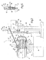
- Number 1 in Figure 2 indicates as a whole a tyre removing machine for removing a tyre 3 of a vehicle wheel 4 from a relative rim 2.
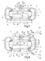
- tyre 3 is a conventional type, and comprises two beads 5 and 6 fitted to respective cylindrical portions 7 and 8 of rim 2 immediately inwards of respective flanges 9 and 10, of which flange 9 is an outer flange.
- Tyre 3 has a known rigid inner run-flat ring 11 comprising a toroidal undulated metal central portion 12; and two beads 13 and 14 made of elastomeric material, fitted to respective axial ends of central portion 12, and fitted to rim 2, adjacent to and inwards of respective beads 5 and 6.
- tyre removing machine 1 comprises a powered turntable 15 having a vertical axis 16 and, on top, a height-adjustable plate 17, which rotates about axis 16, supports wheel 4, and is fitted with a known locating device 18 for engaging flange 10 to lock wheel 4 radially in position, coaxial with axis 16, when rim 2 is placed on plate 17 with flange 10 facing downwards.
- Turntable 15 also has a central hub 19 coaxial with axis 16 and comprising a removable end portion 20 which, in use, projects above flange 9 and provides for locking wheel 4 axially to plate 17.
- End portion 20 comprises a rotary ring 21 coaxial with axis 16, locked axially to hub 19 by a nut 22, and defining an end portion of a connecting device 23, which comprises a fork 24 connected to ring 21 to rotate, with respect to ring 21, about an axis 25 perpendicular to axis 16, and fitted with a front coupling 26 for a tool 27 connectable to hub 19 by connecting device 23 and described in detail below.
- Tyre removing machine 1 also comprises a tool column 28 located alongside turntable 15 and in turn comprising a base 29, from which extends upwards a vertical prismatic guide 30 for a slide 31, which is moved along prismatic guide 30 by a single hydraulic or pneumatic jack 32 interposed between slide 31 and base 29.
- Slide 31 is fitted with a number of known tools - not shown for the sake of simplicity, and hereinafter referred to as "disriding tools" - which act on tyre 3 to detach bead 5 from flange 9 and extract bead 5 from rim 2.
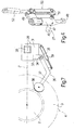
- a bracket 33 projects laterally outwards from a bottom portion of slide 31, and is fitted on its free end, by means of a hinge 34 with an axis 35 parallel to axis 16, with a pressure tool 36 comprising an elbow lever 37, one end of which is connected to bracket 33, and the other end of which is fitted with an upward-sloping pin fitted in rotary manner with a plate 38, the periphery of which lies in a plane sloping slightly upwards towards axis 16.
- the angular position of pressure tool 36 about axis 35 and, therefore, the distance between plate 38 and axis 16 are controllable by a brace 39 ( Figure 7 ) adjustable in length and interposed between slide 31 and an intermediate portion of lever 37.
- tool 27 comprises a lever 40, a first end of which is connected removably to fork 24 by front coupling 26, and a second end of which extends over slide 31 and through a portal 41 integral with slide 31 and extending upwards from the top end of slide 31.
- portal 41 comprises two substantially vertical posts 42 joined by a top cross member 43 and defining between them a gap 44, which lies in a radial plane P ( Figure 7 ) with respect to axis 15, is engaged, in use, by lever 37, and is divided into two parts by a pin 45 parallel to cross member 43 and fitted removably through intermediate portions of posts 42.
- lever 40 comprises a first end fitted removably to front coupling 26 of connecting device 23; a second end extending through gap 44; and an intermediate portion defined by a prismatic guide 46 for fitting, in an adjustable position along lever 40, an intermediate portion of a rod 47 positioned crosswise to lever 40 and extending in radial plane P.
- rod 47 comprises a first end defined by a hook 48, which faces radially outwards with respect to axis 16 when lever 40 is attached to connecting device 23; and a second end above the first end, in use, and fitted with a bracket 49 perpendicular to lever 40 and fitted on its free end with a known toggle tappet 50 comprising a tappet roller 51, which is movable, by a hand lever 52, from a raised rest position (shown by the dash line in Figure 5 ) to a lowered work position (shown by the continuous line in Figure 5 ), in which tappet roller 51 rests, in use, on flange 9 to keep hook 48 in such an axial position, with respect to rim 2, that a portion of bead 13, when engaged by hook 48, is positioned and maintained axially outwards of flange 9.
- a known toggle tappet 50 comprising a tappet roller 51, which is movable, by a hand lever 52, from a raised rest position (shown by the dash line in Figure 5
- lever 40 is fitted to front coupling 26, and rod 47 is locked in position on lever 40 so that the distance between hook 48 and axis 25 is approximately equal to but no less than the radius of flange 9.
- the other end of lever 40 is inserted through gap 44 of portal 41, which is fitted with pin 45 and maintained by slide 31 in a raised position ( Figure 2 ), in which lever 40 rests on a front edge of slide 31 at the base of portal 41.
- jack 32 is operated to lower slide 31, which takes lever 40 with it, by force of gravity, until hook 48 contacts tyre 3 just outside flange 9.
- hook 48 contacts tyre 3 just outside flange 9.
- downward rotation of lever 40 in radial plane P is arrested until, as slide 31 continues moving down into a lowered position not shown, pin 45 comes into contact with lever 40 and draws it down further to insert hook 48 inwards of both bead 5 of tyre 3 and bead 13 of rigid ring 11.
- pressure tool 36 is positioned just below tyre 3, and can be fixed, by adjusting the length of brace 39, so that the periphery of plate 38 is positioned tangent to bead 6, just outwards of flange 10, and substantially in radial plane P.
- Jack 32 is then operated again to move slide 31 back into the raised position in Figure 2 .
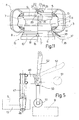
- lever 40 remains in the Figure 9 engaged position, and is simply released by pin 45, whereas pressure tool 36 acts on the tyre to unseat beads 6 and 14 upwards ( Figure 10 ).
- lever 40 is also raised, by rotating about axis 25 in radial plane P, and, in so doing, draws a portion of bead 13 outwards of and over flange 9 ( Figure 10 ).
- toggle tappet 50 until now in the rest position shown by the dash line in Figure 5 , is moved, using hand lever 52, into the work position shown by the continuous line in Figure 5 , and in which tappet roller 51 faces flange 9.
- a slight downward movement of slide 31 at this point brings tappet roller 51 to rest firmly on flange 9, and detaches lever 40 from the front edge of slide 31.
- lever 40 When turntable 15, at this point, is operated, and lever 40 simultaneously locked angularly in radial plane P by portal 41, tappet roller 51 rolls along the whole of flange 9 to extract the whole of bead 13 from flange 9. At this point, lever 40 can be removed, and slide 31 moved into the fully-raised position, to allow pressure tool 36 to remove the whole of tyre 3 and rigid ring 11 off rim 2.
- one jack 32 can be used for all the operations involved in removing tyre 3 and rigid ring 11 off rim 2.
Description
- The present invention relates to a method and machine for removing a tyre, fitted with a rigid inner run-flat ring, from a relative rim.
- In the tyre business, tyre removing machines are known designed to remove a tyre, fitted with a rigid inner run-flat ring, from the relative rim.
- Known tyre removing machines of this sort normally comprise a turntable rotating about an axis; a self-centring clamping device for clamping the rim and relative tyre on, and coaxially with, the turntable; and a hub coaxial and integral with the turntable. Known tyre removing machines of this sort normally also comprise a tool column located alongside the turntable, parallel to the turntable axis, and having a number of hydraulic jacks for operating respective tools, which project towards the turntable from the tool column, and are designed to act on the tyre to detach the tyre beads and rigid inner ring beads from the relative flanges on the rim, and to insert, between the rim, on one side, and a tyre bead and corresponding rigid inner ring bead, on the other, one or more levers by which to move said two beads axially outwards of the relative rim flange.
- Known tyre removing machines of the type described have various drawbacks, on account of the tools projecting from the tool column and so transmitting turning moments to the column which tend to bend the tool column outwards. In the case of a tyre fitted with a rigid inner ring, the forces applied, having to act simultaneously on two side by side beads (the tyre bead and the rigid inner ring bead), are much greater than those applied to a tyre with no rigid inner ring, and tend to produce uncontrolled outward movement of the tools, thus resulting in incorrect use of the tools and, most likely, damage to the tyre and/or rigid inner ring.
-
EP1236589 discloses an implement for demounting and mounting self-supporting tyres of the system pax type and the like, from which a method according to the preamble of claim 1 can be derived. -
- It is an object of the present invention to provide a method and machine for removing a tyre, fitted with a rigid inner run-flat ring, from the relative rim, and which are designed to eliminate the aforementioned drawbacks and, in particular, are cheap and easy to implement.
- According to the present invention, there are provided a method and machine for removing a tyre, fitted with a rigid inner run-flat ring, from a relative rim, as claimed in the accompanying independent Claims and, preferably, in any one of the Claims depending directly or indirectly on the independent Claims.
- A non-limiting embodiment of the present invention will be described by way of example with reference to the accompanying drawings, in which:
-
Figure 1 shows an axial section of a tyre featuring a rigid inner run-flat ring and fitted to a relative rim; -
Figure 2 shows a schematic side view of a preferred embodiment of the tyre removing machine according to the present invention; -
Figure 3 shows a larger-scale axial section of a first detail ofFigure 2 ; -
Figures 4 and5 show a larger-scale view in perspective and side view, respectively, of a second detail ofFigure 2 ; -
Figure 6 shows a larger-scale side view of a third detail ofFigure 2 ; -
Figure 7 shows a larger-scale plan view of a fourth detail ofFigure 2 in a different operating position; -
Figures 8 to 11 show partial larger-scale views of theFigure 2 machine in respective successive operating positions. - Number 1 in
Figure 2 indicates as a whole a tyre removing machine for removing atyre 3 of avehicle wheel 4 from arelative rim 2. - As shown in more detail in
Figure 1 ,tyre 3 is a conventional type, and comprises twobeads cylindrical portions rim 2 immediately inwards ofrespective flanges flange 9 is an outer flange. Tyre 3 has a known rigid inner run-flat ring 11 comprising a toroidal undulated metalcentral portion 12; and twobeads central portion 12, and fitted torim 2, adjacent to and inwards ofrespective beads - As shown in
Figure 2 , tyre removing machine 1 comprises a poweredturntable 15 having avertical axis 16 and, on top, a height-adjustable plate 17, which rotates aboutaxis 16, supportswheel 4, and is fitted with a known locatingdevice 18 forengaging flange 10 to lockwheel 4 radially in position, coaxial withaxis 16, whenrim 2 is placed onplate 17 withflange 10 facing downwards.Turntable 15 also has acentral hub 19 coaxial withaxis 16 and comprising aremovable end portion 20 which, in use, projects aboveflange 9 and provides for lockingwheel 4 axially toplate 17.End portion 20 comprises arotary ring 21 coaxial withaxis 16, locked axially tohub 19 by anut 22, and defining an end portion of a connectingdevice 23, which comprises afork 24 connected toring 21 to rotate, with respect toring 21, about anaxis 25 perpendicular toaxis 16, and fitted with afront coupling 26 for atool 27 connectable tohub 19 by connectingdevice 23 and described in detail below. - Tyre removing machine 1 also comprises a
tool column 28 located alongsideturntable 15 and in turn comprising abase 29, from which extends upwards a verticalprismatic guide 30 for aslide 31, which is moved alongprismatic guide 30 by a single hydraulic orpneumatic jack 32 interposed betweenslide 31 andbase 29. -
Slide 31 is fitted with a number of known tools - not shown for the sake of simplicity, and hereinafter referred to as "disriding tools" - which act ontyre 3 to detachbead 5 fromflange 9 andextract bead 5 fromrim 2. As shown inFigure 2 , and particularly inFigure 8 , abracket 33 projects laterally outwards from a bottom portion ofslide 31, and is fitted on its free end, by means of ahinge 34 with anaxis 35 parallel toaxis 16, with apressure tool 36 comprising anelbow lever 37, one end of which is connected tobracket 33, and the other end of which is fitted with an upward-sloping pin fitted in rotary manner with aplate 38, the periphery of which lies in a plane sloping slightly upwards towardsaxis 16. The angular position ofpressure tool 36 aboutaxis 35 and, therefore, the distance betweenplate 38 andaxis 16 are controllable by a brace 39 (Figure 7 ) adjustable in length and interposed betweenslide 31 and an intermediate portion oflever 37. - As shown in
Figure 2 ,tool 27 comprises alever 40, a first end of which is connected removably to fork 24 byfront coupling 26, and a second end of which extends overslide 31 and through aportal 41 integral withslide 31 and extending upwards from the top end ofslide 31. As shown inFigure 6 ,portal 41 comprises two substantiallyvertical posts 42 joined by atop cross member 43 and defining between them agap 44, which lies in a radial plane P (Figure 7 ) with respect toaxis 15, is engaged, in use, bylever 37, and is divided into two parts by apin 45 parallel tocross member 43 and fitted removably through intermediate portions ofposts 42. - In actual use,
lever 40 comprises a first end fitted removably tofront coupling 26 of connectingdevice 23; a second end extending throughgap 44; and an intermediate portion defined by aprismatic guide 46 for fitting, in an adjustable position alonglever 40, an intermediate portion of arod 47 positioned crosswise to lever 40 and extending in radial plane P. - As shown more clearly in
Figures 4 and5 ,rod 47 comprises a first end defined by ahook 48, which faces radially outwards with respect toaxis 16 whenlever 40 is attached to connectingdevice 23; and a second end above the first end, in use, and fitted with abracket 49 perpendicular to lever 40 and fitted on its free end with a knowntoggle tappet 50 comprising atappet roller 51, which is movable, by ahand lever 52, from a raised rest position (shown by the dash line inFigure 5 ) to a lowered work position (shown by the continuous line inFigure 5 ), in whichtappet roller 51 rests, in use, onflange 9 to keephook 48 in such an axial position, with respect torim 2, that a portion ofbead 13, when engaged byhook 48, is positioned and maintained axially outwards offlange 9. - Operation of tyre removing machine 1 will now be described with reference to a
wheel 4, which has been mounted onturntable 15, withflange 10 ofrelative rim 2 facing downwards and contactingturntable 15, has been positioned coaxially withaxis 16 by locatingdevice 18, and has been locked axially byhub 19; and as of the instant (Figure 8 ) in which bead 5 oftyre 3, previously engaged by said "disriding tools" (not shown), has been extracted fromrelative flange 9. - At this point, one end of
lever 40 is fitted tofront coupling 26, androd 47 is locked in position onlever 40 so that the distance betweenhook 48 andaxis 25 is approximately equal to but no less than the radius offlange 9. The other end oflever 40 is inserted throughgap 44 ofportal 41, which is fitted withpin 45 and maintained byslide 31 in a raised position (Figure 2 ), in whichlever 40 rests on a front edge ofslide 31 at the base ofportal 41. - Next (
Figure 9 ),jack 32 is operated to lowerslide 31, which takeslever 40 with it, by force of gravity, until hook 48contacts tyre 3 just outsideflange 9. Uponhook 48 contactingtyre 3, downward rotation oflever 40 in radial plane P is arrested until, asslide 31 continues moving down into a lowered position not shown,pin 45 comes into contact withlever 40 and draws it down further to inserthook 48 inwards of bothbead 5 oftyre 3 and bead 13 ofrigid ring 11. - When
slide 31 reaches said lowered position not shown,pressure tool 36 is positioned just belowtyre 3, and can be fixed, by adjusting the length ofbrace 39, so that the periphery ofplate 38 is positioned tangent to bead 6, just outwards offlange 10, and substantially in radial plane P. - Jack 32 is then operated again to move
slide 31 back into the raised position inFigure 2 . Over a first part of this movement,lever 40 remains in theFigure 9 engaged position, and is simply released bypin 45, whereaspressure tool 36 acts on the tyre tounseat beads Figure 10 ). On eventually contacting the front edge ofslide 31,lever 40 is also raised, by rotating aboutaxis 25 in radial plane P, and, in so doing, draws a portion ofbead 13 outwards of and over flange 9 (Figure 10 ). This latter movement is assisted bypressure tool 36, which, as it continues moving upwards, pushes the whole oftyre 3, and particularly the part oftyre 3 astride radial plane P, upwards to assist extraction, overflange 9, of the portion ofbead 13 engaged byhook 48. - At this point, toggle tappet 50, until now in the rest position shown by the dash line in
Figure 5 , is moved, usinghand lever 52, into the work position shown by the continuous line inFigure 5 , and in whichtappet roller 51faces flange 9. A slight downward movement ofslide 31 at this point bringstappet roller 51 to rest firmly onflange 9, anddetaches lever 40 from the front edge ofslide 31. - When
turntable 15, at this point, is operated, and lever 40 simultaneously locked angularly in radial plane P byportal 41, tappetroller 51 rolls along the whole offlange 9 to extract the whole ofbead 13 fromflange 9. At this point,lever 40 can be removed, andslide 31 moved into the fully-raised position, to allowpressure tool 36 to remove the whole oftyre 3 andrigid ring 11 offrim 2. - The advantages of tyre removing machine 1, as compared with known machines, are obvious, considering that, on tyre removing machine 1, the tool for removing
rigid ring 11 offrim 2,i.e. tool 27, is hinged tohub 19, as opposed to being connected totool column 28. As a result, despite the force (practically a ton) exerted ontool 27 byjack 32, the distance betweenhook 48 andaxis 16 remains substantially unchanged when removingrigid ring 11, thus practically eliminating any risk ofdamaging tyre 3 when insertinghook 48 betweenbead 13 andrim 2. - Moreover, using
tool 27, onejack 32 can be used for all the operations involved in removingtyre 3 andrigid ring 11 offrim 2.
Claims (19)
- A method of removing, from a relative rim (2), a tyre (3) fitted with a rigid inner run-flat ring (11) having first beads (13, 14), each fitted to the rim (2) inwards of a respective second bead (5; 6) of the tyre (3), the method comprising the steps of:fixing the rim (2) and the tyre (3) onto a turntable (15) having a central hub (19) and rotating about a first axis (16) coaxial with the hub (19);inserting, between the rim (2) and one (5) of the second beads (5, 6) of the tyre (3), a hook (48) carried by a lever (40) hinged to the hub (19);oscillating the lever (40), with respect to the hub (19), in a radial plane (P) of the turntable (15) and about a second axis (25) perpendicular to the first axis (16) and rotating with respect to the first axis (16), so as to exert axial pull on said second bead (5) of the tyre (3) by means of the hook (48), to move a portion of the second bead (5) axially outwards of a relative flange (9) of the rim (2); androtating the turntable (15) about the first axis (16), with the hook (48) still engaging the second bead (5) of the tyre (3), and with the lever (40) locked angularly about the first axis (16);the method being characterized in comprising the further step of:inserting the hook (48) also between the rim (2) and one (13) of the first beads (13, 14) of the inner run-flat ring (11) in order to move a portion of the first bead (13) axially outwards of the relative flange (9) of the rim (2) in one step with the second bead (5) of the tyre (3).
- A method as claimed in Claim 1, wherein, when moving the portion of said first bead (13) axially outwards of the relative flange (9), axial thrust is exerted on the tyre (3) in the same direction as the axial pull exerted by the hook (48) on the first bead (13).
- A method as claimed in Claim 2, wherein the axial thrust is exerted on the tyre (3) close to the other (14) of the first beads (13, 14).
- A method as claimed in Claim 2 or 3, wherein the axial thrust acts substantially in said radial plane (P).
- A method as claimed in one of Claims 2 to 4, wherein the axial pull and axial thrust are applied by one powered actuating member (31) movable parallel to the first axis (16).
- A method as claimed in Claim 5, wherein the hook (48) is inserted between the rim (2) and said first bead (13) by said actuating member (31) oscillating the lever (40) about the second axis (25) and towards the tyre (3).
- A method as claimed in Claim 5 or 6, wherein the lever (40) is locked angularly about the first axis (16) by connecting the lever (40) transversely to said actuating member (31).
- A machine for removing, according to the method as claimed in claim 1, from a relative rim (2), a tyre (3) fitted with a rigid inner run-flat ring (11) having first beads (13, 14), each fitted to the rim (2) inwards of a respective second bead (5; 6) of the tyre (3), the machine (1) comprising:a turntable (15) rotating about a first axis (16);self-centring locking means (18) for locking the rim (2) and the relative tyre (3) coaxially with the first axis (16);a hub (19) coaxial with the first axis (16) and integral with the turntable (15);a tool (27) for engaging and moving one (13) of the second beads (5, 6) axially outwards of a relative flange (9) of the rim (2); the tool (27) comprising a lever (40) hinged to the hub (19) to oscillate, with respect to the hub (19) and in a radial plane (P) of the turntable (15), about a second axis (25) rotating with respect to the hub (19) and perpendicular to the first axis (16); and a hook (48) projecting towards the turntable (15) from the lever (40), and which is inserted between said flange (9) and said second bead (5);the machine (1) being characterized in that the hook (48) is designed to be inserted also between the rim (2) and one (13) of the first beads (13, 14) of the inner run-flat ring (11) in order to contact at the same time both the first bead (13) and the second bead (5) of the tyre (3) to move a portion of the first bead (13) axially outwards of the relative flange (9) of the rim (2) in one step with the second bead (5) of the tyre (3).
- A machine as claimed in Claim 8, and comprising pressure means (36) movable in the same direction as the hook (48), and which engage the tyre (3) to exert axial thrust on the tyre (3).
- A machine as claimed in Claim 9, wherein the pressure means (36) are adjustable in position with respect to the first axis (16), to engage the tyre (3) close to the other (14) of the first beads (13, 14).
- A machine as claimed in Claim 9 or 10, wherein the pressure means (36) are adjustable in position to engage the tyre (3) by a portion of the tyre (3) close to the other (14) of the first beads (13, 14) and located substantially in said radial plane (P).
- A machine as claimed in one of Claims 9 to 11, and comprising a tool column (28) located alongside the turntable (15) and parallel to the first axis (16); and a powered slide (31) movable along the tool column (28) and supporting the pressure means (36); the slide (31) being connected, in use, to the lever (40) to oscillate the lever (40) in said radial plane (P).
- A machine as claimed in Claim 12, wherein the slide (31) is connected, in use, to the lever (40) to lock the lever (40) angularly about the first axis (16).
- A machine as claimed in Claim 12 or 13, wherein the slide (31) has an axial gap (44) having two ends and engaged in sliding manner by a free end of the lever (40); the lever (40) being positioned, in use, contacting one or the other of said ends as it oscillates about the second axis (25).
- A machine as claimed in one of Claims 8 to 14, wherein the hook (48) is fitted to the lever (40) in an adjustable position along the lever (40).
- A machine as claimed in one of Claims 8 to 14, wherein the tool (27) is fitted removably to the hub (19).
- A machine as claimed in Claim 16, wherein the lever (40) is fitted removably to the hub (19) with the interposition of a connecting device (23) fitted in rotary manner to the hub (19).
- A machine as claimed in Claim 17, wherein the connecting device (23) comprises a ring (21) coaxial with the first axis (16) and fitted in rotary and axially-fixed manner to the hub (19); a fork (24) fitted to the ring (21) to oscillate, with respect to the ring (21), about the second axis (25); and a front coupling (26) integral with the fork (24) and for receiving one end of the lever (40) in extractable manner.
- A machine as claimed in one of Claims 8 to 18, wherein the self-centring locking means (18) are arranged in a lower portion of the turntable (15) to engage a lower face of the rim (2) and the hub (19) supporting the lever (40) of the tool (27) is arranged to protrude from an upper face of the rim (2) opposite to the lower face.
Applications Claiming Priority (1)
| Application Number | Priority Date | Filing Date | Title |
|---|---|---|---|
| IT000284A ITTO20060284A1 (en) | 2006-04-14 | 2006-04-14 | METHOD AND MACHINE FOR THE DISASSEMBLY OF A TIRE EQUIPPED WITH AN INTERNAL RIGID ANTI-APPIACTION RING |
Publications (2)
| Publication Number | Publication Date |
|---|---|
| EP1844959A1 EP1844959A1 (en) | 2007-10-17 |
| EP1844959B1 true EP1844959B1 (en) | 2009-03-11 |
Family
ID=38269057
Family Applications (1)
| Application Number | Title | Priority Date | Filing Date |
|---|---|---|---|
| EP07106200A Expired - Fee Related EP1844959B1 (en) | 2006-04-14 | 2007-04-14 | Method and machine for removing a tyre fitted with a rigid inner run-flat ring |
Country Status (5)
| Country | Link |
|---|---|
| US (1) | US7946016B2 (en) |
| EP (1) | EP1844959B1 (en) |
| DE (1) | DE602007000655D1 (en) |
| ES (1) | ES2322674T3 (en) |
| IT (1) | ITTO20060284A1 (en) |
Families Citing this family (5)
| Publication number | Priority date | Publication date | Assignee | Title |
|---|---|---|---|---|
| ITMO20060398A1 (en) * | 2006-12-04 | 2008-06-05 | Gino Ferrari | APPARATUS FOR REMOVAL TIRE MACHINES |
| US8636048B2 (en) | 2008-05-29 | 2014-01-28 | James R. Carawan | Tire run-flat removal and installation machine |
| WO2010110864A2 (en) * | 2009-03-25 | 2010-09-30 | Carawan James R | Tire run-flat ring removal and installation machine |
| IT1396144B1 (en) * | 2009-11-03 | 2012-11-16 | Corghi Spa | LIFTING DEVICE FOR A LOWER SIDE OF A TIRE, IN A TIRE CHANGER MACHINE. |
| WO2016109834A1 (en) * | 2014-12-31 | 2016-07-07 | Applied Biologics, Llc | Denuded amnion flowable tissue graft and method of forming same |
Family Cites Families (6)
| Publication number | Priority date | Publication date | Assignee | Title |
|---|---|---|---|---|
| US2746528A (en) * | 1953-01-26 | 1956-05-22 | Lee J Damman | Tire remover with a rotatable wheel support |
| US2850061A (en) * | 1955-02-25 | 1958-09-02 | Harry G Twiford | Center post for tire changer |
| US2940514A (en) * | 1956-12-06 | 1960-06-14 | Robert D Henderson | Tire demounting tool |
| US3847198A (en) * | 1973-01-30 | 1974-11-12 | Magnum Automotive Equip | Centerpost drive mechanism |
| US4586551A (en) * | 1985-04-09 | 1986-05-06 | Big Four Equipment, Inc. | Centerpost drive for a tire changing machine |
| ITRE20010007U1 (en) | 2001-02-28 | 2002-08-28 | Elett Romeccaniche S I C E S P | PERFECT EQUIPMENT FOR DISASSEMBLY AND ASSEMBLY OF SELF-SUPPORTING TIRES, OF THE SYSTEM PAX TYPE AND SIMILAR. |
-
2006
- 2006-04-14 IT IT000284A patent/ITTO20060284A1/en unknown
-
2007
- 2007-04-13 US US11/785,001 patent/US7946016B2/en not_active Expired - Fee Related
- 2007-04-14 ES ES07106200T patent/ES2322674T3/en active Active
- 2007-04-14 DE DE602007000655T patent/DE602007000655D1/en not_active Expired - Fee Related
- 2007-04-14 EP EP07106200A patent/EP1844959B1/en not_active Expired - Fee Related
Also Published As
| Publication number | Publication date |
|---|---|
| US7946016B2 (en) | 2011-05-24 |
| DE602007000655D1 (en) | 2009-04-23 |
| ES2322674T3 (en) | 2009-06-24 |
| US20080010804A1 (en) | 2008-01-17 |
| ITTO20060284A1 (en) | 2007-10-15 |
| EP1844959A1 (en) | 2007-10-17 |
Similar Documents
| Publication | Publication Date | Title |
|---|---|---|
| EP2233325B1 (en) | Machine for fitting and removing the wheel tyres of vehicle | |
| JP5069830B2 (en) | Automatic tire removal and attachment device and tire removal machine equipped with the device | |
| EP2629992B1 (en) | A tyre demounting machine | |
| EP1897708B1 (en) | Machine for fitting and removing tyres and wheel rims for vehicles | |
| EP1714807B1 (en) | Tool for automatically assembling or disassembling a tyre to/from a wheel rim | |
| EP2599648B1 (en) | Operating head for removing and fitting tyres on rims for vehicles | |
| EP2174807B1 (en) | Operating head for removing and fitting wheel tyres for vehicles | |
| EP1743782B1 (en) | Method and device for dismounting run-flat tyres | |
| EP2282898B1 (en) | A tyre-changing machine and a relative bead-breaking method | |
| EP1844959B1 (en) | Method and machine for removing a tyre fitted with a rigid inner run-flat ring | |
| EP2995478B1 (en) | Machine for removing and fitting wheel tyres for vehicles | |
| US8464775B2 (en) | Tool for tire uninstalling and installing machines | |
| EP1459913B1 (en) | A device for mounting and dismounting tyres | |
| US8381791B2 (en) | Device for lifting a bottom side wall of a tyre in a tyre removing machine | |
| EP2269841B1 (en) | Bead detaching arm, tire demounting method and apparatus using bead detaching arm | |
| EP0805053A2 (en) | Machine for mounting and removing tyres onto and from respective wheel rims | |
| EP1844960B1 (en) | Machine for assembling and disassembling a tyre fitted with a rigid inner run-flat ring | |
| US9610812B2 (en) | Tire bead extraction device for tire-changing machines | |
| EP2756969A1 (en) | Machine for removing/ fitting a tyre from/ on the rim of a vehicle vehicles | |
| US20230123205A1 (en) | Machine for mounting and demounting a tyre relative to a corresponding rim and wheel servicing method | |
| US20080251176A1 (en) | Method and unit for mounting on a rim a tire provided with a safety support | |
| EP1236589A2 (en) | Improved implement for demounting and mounting self-supporting tyres of the system pax type and the like |
Legal Events
| Date | Code | Title | Description |
|---|---|---|---|
| PUAI | Public reference made under article 153(3) epc to a published international application that has entered the european phase |
Free format text: ORIGINAL CODE: 0009012 |
|
| AK | Designated contracting states |
Kind code of ref document: A1 Designated state(s): AT BE BG CH CY CZ DE DK EE ES FI FR GB GR HU IE IS IT LI LT LU LV MC MT NL PL PT RO SE SI SK TR |
|
| AX | Request for extension of the european patent |
Extension state: AL BA HR MK YU |
|
| 17P | Request for examination filed |
Effective date: 20080331 |
|
| AKX | Designation fees paid |
Designated state(s): DE ES FR GB |
|
| GRAP | Despatch of communication of intention to grant a patent |
Free format text: ORIGINAL CODE: EPIDOSNIGR1 |
|
| GRAS | Grant fee paid |
Free format text: ORIGINAL CODE: EPIDOSNIGR3 |
|
| GRAA | (expected) grant |
Free format text: ORIGINAL CODE: 0009210 |
|
| AK | Designated contracting states |
Kind code of ref document: B1 Designated state(s): DE ES FR GB |
|
| REG | Reference to a national code |
Ref country code: GB Ref legal event code: FG4D |
|
| REF | Corresponds to: |
Ref document number: 602007000655 Country of ref document: DE Date of ref document: 20090423 Kind code of ref document: P |
|
| REG | Reference to a national code |
Ref country code: ES Ref legal event code: FG2A Ref document number: 2322674 Country of ref document: ES Kind code of ref document: T3 |
|
| PGFP | Annual fee paid to national office [announced via postgrant information from national office to epo] |
Ref country code: ES Payment date: 20090430 Year of fee payment: 3 |
|
| PGFP | Annual fee paid to national office [announced via postgrant information from national office to epo] |
Ref country code: DE Payment date: 20090430 Year of fee payment: 3 Ref country code: FR Payment date: 20090430 Year of fee payment: 3 |
|
| PLBE | No opposition filed within time limit |
Free format text: ORIGINAL CODE: 0009261 |
|
| STAA | Information on the status of an ep patent application or granted ep patent |
Free format text: STATUS: NO OPPOSITION FILED WITHIN TIME LIMIT |
|
| 26N | No opposition filed |
Effective date: 20091214 |
|
| REG | Reference to a national code |
Ref country code: FR Ref legal event code: ST Effective date: 20101230 |
|
| PG25 | Lapsed in a contracting state [announced via postgrant information from national office to epo] |
Ref country code: DE Free format text: LAPSE BECAUSE OF NON-PAYMENT OF DUE FEES Effective date: 20101103 |
|
| REG | Reference to a national code |
Ref country code: ES Ref legal event code: FD2A Effective date: 20110708 |
|
| PG25 | Lapsed in a contracting state [announced via postgrant information from national office to epo] |
Ref country code: ES Free format text: LAPSE BECAUSE OF NON-PAYMENT OF DUE FEES Effective date: 20110628 |
|
| PG25 | Lapsed in a contracting state [announced via postgrant information from national office to epo] |
Ref country code: ES Free format text: LAPSE BECAUSE OF NON-PAYMENT OF DUE FEES Effective date: 20100415 |
|
| GBPC | Gb: european patent ceased through non-payment of renewal fee |
Effective date: 20110414 |
|
| PG25 | Lapsed in a contracting state [announced via postgrant information from national office to epo] |
Ref country code: GB Free format text: LAPSE BECAUSE OF NON-PAYMENT OF DUE FEES Effective date: 20110414 |
|
| PG25 | Lapsed in a contracting state [announced via postgrant information from national office to epo] |
Ref country code: FR Free format text: LAPSE BECAUSE OF NON-PAYMENT OF DUE FEES Effective date: 20100430 |