EP1474982B1 - Brotbackmaschine - Google Patents
Brotbackmaschine Download PDFInfo
- Publication number
- EP1474982B1 EP1474982B1 EP04250851A EP04250851A EP1474982B1 EP 1474982 B1 EP1474982 B1 EP 1474982B1 EP 04250851 A EP04250851 A EP 04250851A EP 04250851 A EP04250851 A EP 04250851A EP 1474982 B1 EP1474982 B1 EP 1474982B1
- Authority
- EP
- European Patent Office
- Prior art keywords
- tray
- pair
- tray holder
- bread maker
- members
- Prior art date
- Legal status (The legal status is an assumption and is not a legal conclusion. Google has not performed a legal analysis and makes no representation as to the accuracy of the status listed.)
- Expired - Lifetime
Links
Images



Classifications
-
- A—HUMAN NECESSITIES
- A21—BAKING; EDIBLE DOUGHS
- A21B—BAKERS' OVENS; MACHINES OR EQUIPMENT FOR BAKING
- A21B3/00—Parts or accessories of ovens
-
- A—HUMAN NECESSITIES
- A21—BAKING; EDIBLE DOUGHS
- A21B—BAKERS' OVENS; MACHINES OR EQUIPMENT FOR BAKING
- A21B7/00—Baking plants
- A21B7/005—Baking plants in combination with mixing or kneading devices
Definitions
- the present invention relates to bread makers, and more particularly, but not exclusively, to a bread maker in which noise occurring due to a minute movement of a tray member seated in an oven compartment is reduced.
- making bread is a sufficiently complicated process that bread is made by using a bread maker, which automatically performs multiple steps such as kneading, leavening, and baking raw materials of the bread.
- a bread maker disclosed in Korean Patent Publication No. 2001-32188 includes, a housing forming an external structure of a bread maker; a door provided to the housing; and a Liquid Crystal Display (“LCD”) display part provided to a side front part of the housing.
- LCD Liquid Crystal Display
- upper and lower rollers which are rotatably disposed in parallel to wind opposite ends of a mixing bag. Between the upper and lower rollers is placed a pair of dough-blocking members to prevent the raw materials kneaded in the mixing bag from moving to the upper roller.
- a baking tray which can be drawn out, to contain kneaded materials therein.
- the baking tray is of a box shape having a top opening formed with combination of a stationary part and a movable part that are symmetrical to one another.
- the movable part is combined with pivot holders via pivot elements and/or techniques.
- the raw materials contained in the mixing bag are reciprocated up and down via the upper and lower rollers during a kneading process, thereby being kneaded between the dough-blocking members and the baking tray. After the kneading process is completed, the mixing bag is removed and dough contained in the baking tray is baked.
- the mixing bag is moved up and down during the kneading process through the slit of the baking tray formed between the stationary and movable parts.
- the baking tray seated inside the housing is also moved up and down. Therefore, inner surfaces of the housing in which the baking tray is seated and the baking tray are in direct contact with each other, thereby, causing noise during the bread making process.
- the conventional bread maker presents a problem because as the baking tray is slightly moved up and down during the kneading process, the baking tray is in direct contact with the inner surface of the housing, and as a result, makes noise.
- the present invention provides, a bread maker comprising: a main body forming an oven compartment provided with upper and lower kneading drums which are placed spaced from each other in upper and lower parts of the oven compartment to hold opposite ends of a mixing bag, respectively, and to wind the mixing bag; a pair of tray members disposed between the upper and the lower kneading drums facing each other to form a slit to pass the mixing bag therethrough; tray holder members combined with opposite ends of the pair of tray members; a pair of guides mounted on inner sidewalls of the oven compartment facing each other to slidably guide the tray holder members by slidingly combining with the tray holder members; and a shock absorber introduced between the tray holder member and the guide.
- the shock absorber is adhered to one of the tray holder member and the guide.
- the guide comprises: a mounting surface mounted on an inner sidewall of the oven compartment; a seating surface extending from the lower edge of the mounting surface to accommodate the lower surface of the tray holder member; and an upper surface extending from the upper edge of the mounting surface and oppositely spaced from the seating surface by a predetermined distance.
- the upper surface is formed with a narrow part of a width narrower than the transverse width of the seating surface and a broad part of the same width as the width of transverse width of the seating surface.
- the pair of tray members includes a stationary tray member to be mounted on the tray holder member and a movable tray member to be movably mounted on the tray holder member.
- the narrow part of the upper surface is almost the same length as the transverse width of the movable tray member.
- the shock absorber comprises: a first shock absorber adhered to the inner surface of the broad part of the upper surface of the pair of guides; and a second shock absorber adhered to the seating surface of the pair of guides.
- the shock absorber includes a nonmetal insulation material with elasticity.
- FIG 1 is a perspective view of a bread maker provided with a baking tray according to an embodiment the present invention.
- a bread maker according to an embodiment of the present invention, comprises: a main body 1 provided with an oven compartment 10; a door 3 in the front of the main body 1 to rotatably open and close a front opening of the oven compartment 10; and an operation display panel 2 provided at a side portion of the front of the main body 1 to display an operation state of the main body 1.
- upper and lower kneading drums 11 and 12 which are disposed in parallel and wind upper and lower ends of a mixing bag filled with raw materials needed for making the bread.
- the kneading drums 11 and 12 rotate in clockwise and counterclockwise directions.
- a pair of dough-blocking members 13 (only one shown) to prevent the raw materials kneaded in the mixing bag from moving to the upper kneading drum 11.
- a baking tray assembly 20, which can be drawn out from the oven compartment 10 that contains kneaded materials needed to make the bread is provided between the upper and lower kneading drums 11 and 12 towards the lower part of the oven compartment 10.
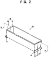
- the baking tray 30 is of a box shape, with a top opening formed by combining stationary and movable tray members 31 and 33 of an "L" shaped section symmetrical to each other. Further provided is a pair of tray holder members 40 connected to opposite ends of the stationary and movable tray members 31 and 33, respectively.
- stationary projections (not shown) to be securely combined with the pair of tray holder members 40 are projected from exterior surfaces of the opposite sidewalls.
- combining projections 34 to be movably combined with the pair of tray holder members 40 are projected from exterior surfaces of the opposite sidewalls.
- the pair of tray holder members 40 are slidingly combined with guides 14 mounted facing each other on opposite inner sidewalls of the oven compartment 10.
- As parts to be combined with the stationary tray member 31 are stationary projections accommodating parts (not shown) grooved on the tray holder member 40 where the stationary projections of the stationary tray member 31 are inserted.
- As parts to be combined with the movable tray member 33 are guide grooves 42 formed on the tray holder member 40 where the combining projections 34 of the movable tray member 33 are movably inserted.
- the stationary tray member 31 Upon insertion of the stationary projections of the stationary tray member 31 in the stationary projections accommodating parts (not shown) of the tray holder member 40, the stationary tray member 31 is securely mounted on the tray holder member 40. Similarly, upon insertion of the combining projections 34 of the movable tray member 33 in the guide grooves 42 of the tray holder member 40, the movable tray member 33 is movably mounted on the tray holder member 40.
- the baking tray 30 which is of a box shape having a top opening to contain the raw materials for the bread is formed.
- a slit 21 is formed along the line at which the stationary and movable tray members 31 and 33 are combined.
- the tray holder member 40 of the baking tray assembly 20 is slidingly combined with the guide 14 of the oven compartment 10 so that the baking tray assembly 20 can be slidably seated inside the oven compartment 10.
- the guides 14 are employed to guide a sliding movement of the tray holder member 40 and form a pair facing each other on the opposite inner sidewalls of the oven compartment 10.
- the guide 14 comprises: a mounting surface 51 mounted on each inner sidewall of the oven compartment 10; a seating surface 52 extending from the lower edge of the mounting surface 51 on which the lower surface of the tray holder member 40 is seated; and an upper surface 53 extending from the upper edge of the mounting surface 51 and oppositely spaced from the seating surface 52 by a predetermined distance.
- the upper surface 53 of the guide 14 is formed of a narrow part 54 with a width narrower than the transverse width of the seating surface 52; and a broad part 55, which is almost the same width as the width of the transverse width of the seating surface 52.
- the narrow part 54 is almost of the same length as the transverse width c of the movable tray member 33 as shown in Figure 2 in the combination state of the guide 14 and the tray holder member 40.
- the broad part 55 is almost of the same length as the transverse width d (shown in Figure 2) of the stationary tray member 31 as shown in Figure 2.
- a shock absorber 60 is provided between the guide 14 and the tray holder member 40 to prevent the tray holder member 40 from minute movement in the vertical direction during the winding of the upper and lower kneading drums 11 and 12 in clockwise and counterclockwise directions.
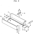
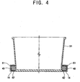
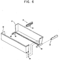
- the shock absorber 60 is made of non-metal insulation material with a predetermined elasticity, for example, rubber, silicon or etc. As shown in Figure 3 and 4, according to an embodiment of the invention, the shock absorber 60, comprises: a first shock absorber 61 adhered to the upper surface of the tray holder member 40 in contact with the broad part 55 of the upper surface 53 of the guide 14; and a second shock absorber 62 adhered to the lower surface of the tray holder member 40. As shown in Figure 5 illustrating a second embodiment of the invention, a first shock absorber 61a may be adhered to the inner surface of the bread part 55 of the upper surface 53 of the guide 14, and a second shock absorber 62a may be adhered to the seating surface 52 of the guide 14.
- non-metal insulation material with a predetermined elasticity may be applied on surfaces which need the shock-absorbing material to provide the surfaces with a benefit similar to the one provided via the shock absorber 60 provided between the guide 14 and the tray holder member 40.
- one end of the mixing bag contained inside the oven compartment 10 is wound by the upper kneading drum 11. Then, the other end of the mixing bag passes through the pair of dough-blocking members 13 and the slit 21 formed at the bottom of the baking tray 30 and then is wound by the lower kneading drum 12.
- the mixing bag filled with raw materials for bread is reciprocated up and down by the upper and lower kneading drums 11 and 12 during the kneading process so that the raw materials for the bread are kneaded between the pair of dough-blocking members 13 and the baking tray 30.
- the mixing bag is released from the upper kneading drum 11 as the lower kneading drum 12 is the only kneading drum being rotated. Then, the mixing bag passes through the pair of dough-blocking members 13 and finally the slit 21 formed at the bottom of the baking tray 30.
- the mixing bag passes through the slit 21 of the baking tray 30 since the raw materials for the bread contained in the mixing bag cannot pass the slit 21 of the baking tray 30, the raw materials for the bread are separated from the mixing bag and contained in the baking tray 30.
- the mixing bag can pass the slit 21 of the baking tray 30 and is wound by the lower kneading drum 12. Thereafter, the raw materials for the bread contained in the baking tray 30 are baked by the baking heater 16.
- the shock absorber 60 prevents minute movement of the tray holder member 40 in a vertical direction within the guide 14. Therefore, the noise occurring when the guide 14 and the tray holder member 40 are in direct contact can be prevented.
- the shock absorber 60 between the guide 14 and the tray holder member 40 prevents minute movement of the tray holder member 40 within the guide 14. Consequently, the noise occurring due to direct contact of the guide 14 and tray holder member 40 can be prevented, thereby, offering a reliable bread maker to a user.
Landscapes
- Life Sciences & Earth Sciences (AREA)
- Engineering & Computer Science (AREA)
- Food Science & Technology (AREA)
- Baking, Grill, Roasting (AREA)
- Food-Manufacturing Devices (AREA)
Claims (13)
- Brotbackmaschine mit einem Hauptkörper (1), der eine Ofenkammer (10) bildet, mit:einem Paar von einander gegenübertiegend vorgesehenen Schalenteilen (31. 33), um einen Spalt zu bilden, um eine Rohmaterialien für ein Brot enthaltende Mischtasche hindurchtreten zu lassen;einem Paar von Schalenhalterelementen (40), die mit einander entgegengesetzten Selten des Paares der Schalenteile (31, 33) verbunden sind-,einem Paar von Führungen (14), die auf Inneren Seitenwänden der Ofenkammer (10) befestigt sind und einander gegenüberliegen, um verschiebbar die Schalenhalterelemente (40) zu führen, indem sie gleitend mit den Schalenhalterelementen (40) zusammenwirken,
dadurch gekennzeichnet,
dass sie außerdem aufweist:einen Stoßdämpfer (BD), der zwischen die Schalenhalteralemente (40) und die Führungen (14) eingefügt wird, - Brotbackmaschine nach Anspruch 1, in welcher der Stoßdämpfer (60) an einem der Schalenhalterelemente (40) oder der Führungen (14) angebracht ist.
- Brotbackmaschine nach Anspruch 1 oder 2, In welcher das Paar von Führungen außerdem aufweist:eine Montagefläche (51), die auf einer inneren Seiterwand der Ofenkammer (10) befestigt ist,eine Auflagefläche (52), die sich von der unteren Kante der Montagefläche (51) aus erstreckt, um die Unterselte der Schalenhalterelemente (40) aufzunehmen; undeine Oberseite (53), die sich von der oberen Kante der Montagefläche (51) aus erstreckt und In einem vorbestimmten Abstand der Auflagefläche (52) gagenüberliegt, wobei die Oberseite (53) mit einem schmalen Abschnitt (54) mit einer Breite ausgeblidet ist, die schmaler ist als die In Querrichtung liegende Breite der Auflagefläche (52) und mit einem breiten Abschnitt (55), der genauso breit ist wie die in Querrichtung liegende Breite der Auflagefläche (52).
- Brotbackmaschine nach Anspruch 3, In welcher das Paar von Schalenteilen (31, 33) außerdem aufweist:ein stationäres Schalenteil (31), das auf dem Schalenhalterelement (40) befestigt ist, undein bewegliches Schalenteil (33), das beweglich auf dem Schalenhalterelement (40) befestigt ist.
- Brotbackmaschine nach einem der vorstehenden Ansprüche, in welchem der Stoßdämpfer (60) außerdem aufweist:einen ersten Stoßdämpfer (61), der an der Oberseite des Schalenhalterelements (40) angebracht ist und in Kontakt mit dem breiten Abschnitt (55) der Oberseite der Führung (14) steht; undeinen zweiten Stoßdämpfer (62), der an der Unterseite des Schalenhalterelementes (40) angebracht ist.
- Brotbackmaschine nach einem der Ansprüche 1 bis 4, in welchem der Stoßdämpfer (60) außerdem aufweist:einen ersten Stoßdämpfer (61a), der an der Innenseite des breiten Abschnittes (65) der Oberseite des Paares von Führungen (14) angebracht ist; undeinen zweiten Stoßdämpfer (62a), der an der Auflagefläche (52) des Paares von Führungen (14) angebracht ist.
- Brotbackmaschine nach einem der vorstehenden Ansprüche, In welchem der Stoßdämpfer (60) ein nichtmetallisches Isolationsmaterial mit Elastizität einschließt.
- Brotbackmaschine nach Anspruch 7, in welchem das nichtmetallische Isolationsmaterial auf Oberflächen aufgetragen ist, die ein stoßabsorbisrendes Material benötigen.
- Brotbackmaschine nach Anspruch 4 oder einem der Ansprüche 5 bis 8, soweit diese direkt oder indirekt auf Ampruch 4 zurückbezogen sind, außerdem aufweisend:wenigstens ein stationäres Vorsprungselement, das einander gegenüberliegenden äußeren Seitenwänden der stationären Schalentelle (31) zur Verfügung steht, um sich fest mit dem Paar von Schalenhalterelementen (40) zu verbinden; undwenigstens ein verbindendes Vorsprungslement (34), das den gegenüberliegenden äußeren Seitenwänden des beweglichen Schalenteiles (33) zur Verfügung steht, um sich beweglich mit dem Paar von Schalenhalterelementen (40) zu verbinden.
- Brotbackmaschine nach einem der vorstehenden Ansprüche, in welchem das Paar von Schalenhalterelementen (40) verschiebbar mit dem Paar von Führungen (14) verbunden ist, die auf den Inneren Seitenwänden der Ofenkammer (10) befestigt sind.
- Brotbackmaschine nach Anspruch 9 oder Anspruch 10, soweit dieser auf Anspruch 9 zurückbezogen sind, außerdem sufweisend:einen den stationären Vorsprung aufnehmenden, in eine erste Seite des Paares von Schalenhalterelementen (40) vertieften Abschnitt zur Verbindung mit dem wenigstens einen stationären Vorsprung; undFührungsnuten (42), die auf einer zweiten seite des Paares von Schalenhalterelementen (40) ausgebildet sind, um die Einfügung des wenigstens einen verbindenden Vorsprungselements (34) des beweglichen Schalenteiles (33) zu erlauben.
- Brotbackmaschine nach Anspruch 4 oder einem der Ansprüche 5 bis 11, soweit diese direkt oder indirekt auf Anspruch 4 zurückbezogen sind,
wobei der schmale Abschnitt (54) der Oberseite der Führung von im Wesentlichen der gleichen Länge wie die Breite (c) des beweglichen Schalenteiles (33) in Querrichtung ist. - Brotbackmaschine, aufweisend:einen Hauptkörper (1) der eine Ofenkammer (10) bildet;eine obere und untere Knettrommel (11, 12), die mit einem Abstand voneinander in oberen und unteren Teilen der Ofenkammer (10) vorgesehen sind, um jeweils Seiten einer Mischtasche zu halten und die Mischtasche aufzuwickeln;einem Paar von Schalentellen (31, 33), die zwischen den oberen und den unteren Kneltrommeln (11, 12) angeordnet sind, die einander gegenüberliegen und einen Spalt ausbilden, um es der Mieschtasche zu erlauben, dort hindurch zu treten;einem Paar von Schalenhalterelementen (40), die mit einander entgegengesetzten Seiten des Paares von Schalenteilen (31,33) verbunden sind;einem Paar von Führungen (14), die auf den Inneren Seitenwänden der Ofenkammer (10) befestigt sind und einander gegenübertiegen, um die Schalenhalterelemente (40) verschiebbar zu führen, indem sie gleitend mit den Schalenhalterelementen (40) zusammenwirken;
dadurch gekennzeichnet,
dass sie außerdem aufweist:einen Stoßdämpfer (60), der zwischen den Schalenhalterelementen (40) und den Führungen (14) eingefügt ist.
Applications Claiming Priority (2)
| Application Number | Priority Date | Filing Date | Title |
|---|---|---|---|
| KR2003029088 | 2003-05-07 | ||
| KR1020030029088A KR20040096216A (ko) | 2003-05-07 | 2003-05-07 | 제빵기 |
Publications (2)
| Publication Number | Publication Date |
|---|---|
| EP1474982A1 EP1474982A1 (de) | 2004-11-10 |
| EP1474982B1 true EP1474982B1 (de) | 2006-02-01 |
Family
ID=36089215
Family Applications (1)
| Application Number | Title | Priority Date | Filing Date |
|---|---|---|---|
| EP04250851A Expired - Lifetime EP1474982B1 (de) | 2003-05-07 | 2004-02-18 | Brotbackmaschine |
Country Status (6)
| Country | Link |
|---|---|
| US (1) | US7267046B2 (de) |
| EP (1) | EP1474982B1 (de) |
| JP (1) | JP3761555B2 (de) |
| KR (1) | KR20040096216A (de) |
| CN (1) | CN1265713C (de) |
| DE (1) | DE602004000366T2 (de) |
Families Citing this family (1)
| Publication number | Priority date | Publication date | Assignee | Title |
|---|---|---|---|---|
| IT1400218B1 (it) * | 2009-03-24 | 2013-05-24 | De Longhi Appliances Srl | Elettrodomestico per la produzione di pane |
Family Cites Families (8)
| Publication number | Priority date | Publication date | Assignee | Title |
|---|---|---|---|---|
| JP2904298B2 (ja) | 1990-03-30 | 1999-06-14 | マツダ株式会社 | 車両用多重伝送装置 |
| GB2277789B (en) * | 1993-05-07 | 1997-04-09 | Gary John Turner | Vibration isolation platform |
| TW391867B (en) * | 1997-11-17 | 2000-06-01 | Heden Team Ag | Automatic baking apparatus and mixbag thereof |
| KR20020053646A (ko) | 2000-12-27 | 2002-07-05 | 윤종용 | 제빵기 |
| KR100632731B1 (ko) * | 2000-12-30 | 2006-10-11 | 삼성전자주식회사 | 제빵기 |
| MX2007008676A (es) | 2005-01-19 | 2007-07-25 | Hoffmann La Roche | Derivados de 5-aminoindol. |
| KR100904466B1 (ko) | 2007-12-11 | 2009-06-24 | 주식회사 하이닉스반도체 | 온 다이 터미네이션 장치의 터미네이션 회로 |
| KR100905774B1 (ko) | 2009-04-03 | 2009-07-02 | (주)빅하우스 | 소독약 투입기용 물 분배기 |
-
2003
- 2003-05-07 KR KR1020030029088A patent/KR20040096216A/ko not_active Withdrawn
-
2004
- 2004-02-18 DE DE602004000366T patent/DE602004000366T2/de not_active Expired - Lifetime
- 2004-02-18 EP EP04250851A patent/EP1474982B1/de not_active Expired - Lifetime
- 2004-02-20 CN CNB2004100070072A patent/CN1265713C/zh not_active Expired - Fee Related
- 2004-03-22 US US10/805,477 patent/US7267046B2/en not_active Expired - Fee Related
- 2004-03-30 JP JP2004101453A patent/JP3761555B2/ja not_active Expired - Fee Related
Also Published As
| Publication number | Publication date |
|---|---|
| CN1550147A (zh) | 2004-12-01 |
| JP3761555B2 (ja) | 2006-03-29 |
| US7267046B2 (en) | 2007-09-11 |
| JP2004329905A (ja) | 2004-11-25 |
| KR20040096216A (ko) | 2004-11-16 |
| US20040261628A1 (en) | 2004-12-30 |
| DE602004000366D1 (de) | 2006-04-13 |
| CN1265713C (zh) | 2006-07-26 |
| EP1474982A1 (de) | 2004-11-10 |
| DE602004000366T2 (de) | 2006-10-12 |
Similar Documents
| Publication | Publication Date | Title |
|---|---|---|
| EP1474982B1 (de) | Brotbackmaschine | |
| KR100471073B1 (ko) | 제빵기 | |
| EP1474980B1 (de) | Brotbackmaschine | |
| US6745670B2 (en) | Bread maker | |
| US20040221733A1 (en) | Bread maker | |
| US20040221729A1 (en) | Bread maker | |
| EP1475020B1 (de) | Brotbackmaschine | |
| EP1475019B1 (de) | Brotbackmaschine | |
| EP1477064B1 (de) | Eine Brotbackmaschine | |
| EP1474987B1 (de) | Brotbackmaschine | |
| EP1474979B1 (de) | Brotbackgerät | |
| KR100802174B1 (ko) | 냉장고용 바스켓 출납구조 | |
| KR100406308B1 (ko) | 제빵기 | |
| US20040221727A1 (en) | Bread maker | |
| JP2021076284A (ja) | 冷蔵庫 | |
| US20040221739A1 (en) | Bread maker | |
| JPH09206238A (ja) | トイレットペーパーホルダー | |
| KR20040096094A (ko) | 제빵기 | |
| KR20200049987A (ko) | 슬라이딩 도어용 하부레일 | |
| JP2008094330A (ja) | カップホルダ装置 |
Legal Events
| Date | Code | Title | Description |
|---|---|---|---|
| PUAI | Public reference made under article 153(3) epc to a published international application that has entered the european phase |
Free format text: ORIGINAL CODE: 0009012 |
|
| 17P | Request for examination filed |
Effective date: 20040218 |
|
| AK | Designated contracting states |
Kind code of ref document: A1 Designated state(s): AT BE BG CH CY CZ DE DK EE ES FI FR GB GR HU IE IT LI LU MC NL PT RO SE SI SK TR |
|
| AX | Request for extension of the european patent |
Extension state: AL LT LV MK |
|
| GRAP | Despatch of communication of intention to grant a patent |
Free format text: ORIGINAL CODE: EPIDOSNIGR1 |
|
| GRAS | Grant fee paid |
Free format text: ORIGINAL CODE: EPIDOSNIGR3 |
|
| AKX | Designation fees paid |
Designated state(s): DE FR GB SE |
|
| GRAA | (expected) grant |
Free format text: ORIGINAL CODE: 0009210 |
|
| AK | Designated contracting states |
Kind code of ref document: B1 Designated state(s): DE FR GB SE |
|
| REG | Reference to a national code |
Ref country code: GB Ref legal event code: FG4D |
|
| REF | Corresponds to: |
Ref document number: 602004000366 Country of ref document: DE Date of ref document: 20060413 Kind code of ref document: P |
|
| REG | Reference to a national code |
Ref country code: SE Ref legal event code: TRGR |
|
| ET | Fr: translation filed | ||
| PLBE | No opposition filed within time limit |
Free format text: ORIGINAL CODE: 0009261 |
|
| STAA | Information on the status of an ep patent application or granted ep patent |
Free format text: STATUS: NO OPPOSITION FILED WITHIN TIME LIMIT |
|
| 26N | No opposition filed |
Effective date: 20061103 |
|
| PGFP | Annual fee paid to national office [announced via postgrant information from national office to epo] |
Ref country code: FR Payment date: 20110218 Year of fee payment: 8 Ref country code: SE Payment date: 20110211 Year of fee payment: 8 Ref country code: DE Payment date: 20110216 Year of fee payment: 8 |
|
| PGFP | Annual fee paid to national office [announced via postgrant information from national office to epo] |
Ref country code: GB Payment date: 20110216 Year of fee payment: 8 |
|
| GBPC | Gb: european patent ceased through non-payment of renewal fee |
Effective date: 20120218 |
|
| PG25 | Lapsed in a contracting state [announced via postgrant information from national office to epo] |
Ref country code: SE Free format text: LAPSE BECAUSE OF NON-PAYMENT OF DUE FEES Effective date: 20120219 |
|
| REG | Reference to a national code |
Ref country code: FR Ref legal event code: ST Effective date: 20121031 |
|
| REG | Reference to a national code |
Ref country code: DE Ref legal event code: R119 Ref document number: 602004000366 Country of ref document: DE Effective date: 20120901 |
|
| PG25 | Lapsed in a contracting state [announced via postgrant information from national office to epo] |
Ref country code: GB Free format text: LAPSE BECAUSE OF NON-PAYMENT OF DUE FEES Effective date: 20120218 Ref country code: FR Free format text: LAPSE BECAUSE OF NON-PAYMENT OF DUE FEES Effective date: 20120229 |
|
| PG25 | Lapsed in a contracting state [announced via postgrant information from national office to epo] |
Ref country code: DE Free format text: LAPSE BECAUSE OF NON-PAYMENT OF DUE FEES Effective date: 20120901 |