EP1474347B1 - Belt conveyor - Google Patents
Belt conveyor Download PDFInfo
- Publication number
- EP1474347B1 EP1474347B1 EP03739711A EP03739711A EP1474347B1 EP 1474347 B1 EP1474347 B1 EP 1474347B1 EP 03739711 A EP03739711 A EP 03739711A EP 03739711 A EP03739711 A EP 03739711A EP 1474347 B1 EP1474347 B1 EP 1474347B1
- Authority
- EP
- European Patent Office
- Prior art keywords
- belt
- conveyor
- roller
- zones
- rollers
- Prior art date
- Legal status (The legal status is an assumption and is not a legal conclusion. Google has not performed a legal analysis and makes no representation as to the accuracy of the status listed.)
- Revoked
Links
- 230000004044 response Effects 0.000 claims abstract description 12
- 230000007423 decrease Effects 0.000 claims description 11
- 238000009825 accumulation Methods 0.000 claims description 10
- JOYRKODLDBILNP-UHFFFAOYSA-N Ethyl urethane Chemical compound CCOC(N)=O JOYRKODLDBILNP-UHFFFAOYSA-N 0.000 description 4
- 239000004677 Nylon Substances 0.000 description 2
- 229920001971 elastomer Polymers 0.000 description 2
- 238000001125 extrusion Methods 0.000 description 2
- 239000000463 material Substances 0.000 description 2
- 229920001778 nylon Polymers 0.000 description 2
- 229920000728 polyester Polymers 0.000 description 2
- 238000011144 upstream manufacturing Methods 0.000 description 2
- 238000012986 modification Methods 0.000 description 1
- 230000004048 modification Effects 0.000 description 1
- 238000012544 monitoring process Methods 0.000 description 1
- 229920002635 polyurethane Polymers 0.000 description 1
- 239000004814 polyurethane Substances 0.000 description 1
- 238000005096 rolling process Methods 0.000 description 1
- 230000001360 synchronised effect Effects 0.000 description 1
Images


Classifications
-
- B—PERFORMING OPERATIONS; TRANSPORTING
- B65—CONVEYING; PACKING; STORING; HANDLING THIN OR FILAMENTARY MATERIAL
- B65G—TRANSPORT OR STORAGE DEVICES, e.g. CONVEYORS FOR LOADING OR TIPPING, SHOP CONVEYOR SYSTEMS OR PNEUMATIC TUBE CONVEYORS
- B65G15/00—Conveyors having endless load-conveying surfaces, i.e. belts and like continuous members, to which tractive effort is transmitted by means other than endless driving elements of similar configuration
- B65G15/30—Belts or like endless load-carriers
- B65G15/32—Belts or like endless load-carriers made of rubber or plastics
-
- B—PERFORMING OPERATIONS; TRANSPORTING
- B65—CONVEYING; PACKING; STORING; HANDLING THIN OR FILAMENTARY MATERIAL
- B65G—TRANSPORT OR STORAGE DEVICES, e.g. CONVEYORS FOR LOADING OR TIPPING, SHOP CONVEYOR SYSTEMS OR PNEUMATIC TUBE CONVEYORS
- B65G15/00—Conveyors having endless load-conveying surfaces, i.e. belts and like continuous members, to which tractive effort is transmitted by means other than endless driving elements of similar configuration
- B65G15/22—Conveyors having endless load-conveying surfaces, i.e. belts and like continuous members, to which tractive effort is transmitted by means other than endless driving elements of similar configuration comprising a series of co-operating units
-
- B—PERFORMING OPERATIONS; TRANSPORTING
- B65—CONVEYING; PACKING; STORING; HANDLING THIN OR FILAMENTARY MATERIAL
- B65G—TRANSPORT OR STORAGE DEVICES, e.g. CONVEYORS FOR LOADING OR TIPPING, SHOP CONVEYOR SYSTEMS OR PNEUMATIC TUBE CONVEYORS
- B65G15/00—Conveyors having endless load-conveying surfaces, i.e. belts and like continuous members, to which tractive effort is transmitted by means other than endless driving elements of similar configuration
- B65G15/22—Conveyors having endless load-conveying surfaces, i.e. belts and like continuous members, to which tractive effort is transmitted by means other than endless driving elements of similar configuration comprising a series of co-operating units
- B65G15/24—Conveyors having endless load-conveying surfaces, i.e. belts and like continuous members, to which tractive effort is transmitted by means other than endless driving elements of similar configuration comprising a series of co-operating units in tandem
-
- B—PERFORMING OPERATIONS; TRANSPORTING
- B65—CONVEYING; PACKING; STORING; HANDLING THIN OR FILAMENTARY MATERIAL
- B65G—TRANSPORT OR STORAGE DEVICES, e.g. CONVEYORS FOR LOADING OR TIPPING, SHOP CONVEYOR SYSTEMS OR PNEUMATIC TUBE CONVEYORS
- B65G15/00—Conveyors having endless load-conveying surfaces, i.e. belts and like continuous members, to which tractive effort is transmitted by means other than endless driving elements of similar configuration
- B65G15/30—Belts or like endless load-carriers
- B65G15/50—Endless load-carriers consisting of a series of parallel ropes or belt strips
-
- B—PERFORMING OPERATIONS; TRANSPORTING
- B65—CONVEYING; PACKING; STORING; HANDLING THIN OR FILAMENTARY MATERIAL
- B65G—TRANSPORT OR STORAGE DEVICES, e.g. CONVEYORS FOR LOADING OR TIPPING, SHOP CONVEYOR SYSTEMS OR PNEUMATIC TUBE CONVEYORS
- B65G15/00—Conveyors having endless load-conveying surfaces, i.e. belts and like continuous members, to which tractive effort is transmitted by means other than endless driving elements of similar configuration
- B65G15/60—Arrangements for supporting or guiding belts, e.g. by fluid jets
- B65G15/64—Arrangements for supporting or guiding belts, e.g. by fluid jets for automatically maintaining the position of the belts
-
- B—PERFORMING OPERATIONS; TRANSPORTING
- B65—CONVEYING; PACKING; STORING; HANDLING THIN OR FILAMENTARY MATERIAL
- B65G—TRANSPORT OR STORAGE DEVICES, e.g. CONVEYORS FOR LOADING OR TIPPING, SHOP CONVEYOR SYSTEMS OR PNEUMATIC TUBE CONVEYORS
- B65G39/00—Rollers, e.g. drive rollers, or arrangements thereof incorporated in roller-ways or other types of mechanical conveyors
- B65G39/02—Adaptations of individual rollers and supports therefor
-
- B—PERFORMING OPERATIONS; TRANSPORTING
- B65—CONVEYING; PACKING; STORING; HANDLING THIN OR FILAMENTARY MATERIAL
- B65G—TRANSPORT OR STORAGE DEVICES, e.g. CONVEYORS FOR LOADING OR TIPPING, SHOP CONVEYOR SYSTEMS OR PNEUMATIC TUBE CONVEYORS
- B65G39/00—Rollers, e.g. drive rollers, or arrangements thereof incorporated in roller-ways or other types of mechanical conveyors
- B65G39/02—Adaptations of individual rollers and supports therefor
- B65G39/07—Other adaptations of sleeves
- B65G39/071—Other adaptations of sleeves for aligning belts or sheets
-
- B—PERFORMING OPERATIONS; TRANSPORTING
- B65—CONVEYING; PACKING; STORING; HANDLING THIN OR FILAMENTARY MATERIAL
- B65G—TRANSPORT OR STORAGE DEVICES, e.g. CONVEYORS FOR LOADING OR TIPPING, SHOP CONVEYOR SYSTEMS OR PNEUMATIC TUBE CONVEYORS
- B65G43/00—Control devices, e.g. for safety, warning or fault-correcting
- B65G43/10—Sequence control of conveyors operating in combination
-
- B—PERFORMING OPERATIONS; TRANSPORTING
- B65—CONVEYING; PACKING; STORING; HANDLING THIN OR FILAMENTARY MATERIAL
- B65G—TRANSPORT OR STORAGE DEVICES, e.g. CONVEYORS FOR LOADING OR TIPPING, SHOP CONVEYOR SYSTEMS OR PNEUMATIC TUBE CONVEYORS
- B65G47/00—Article or material-handling devices associated with conveyors; Methods employing such devices
- B65G47/22—Devices influencing the relative position or the attitude of articles during transit by conveyors
- B65G47/26—Devices influencing the relative position or the attitude of articles during transit by conveyors arranging the articles, e.g. varying spacing between individual articles
- B65G47/261—Accumulating articles
-
- B—PERFORMING OPERATIONS; TRANSPORTING
- B65—CONVEYING; PACKING; STORING; HANDLING THIN OR FILAMENTARY MATERIAL
- B65G—TRANSPORT OR STORAGE DEVICES, e.g. CONVEYORS FOR LOADING OR TIPPING, SHOP CONVEYOR SYSTEMS OR PNEUMATIC TUBE CONVEYORS
- B65G47/00—Article or material-handling devices associated with conveyors; Methods employing such devices
- B65G47/22—Devices influencing the relative position or the attitude of articles during transit by conveyors
- B65G47/26—Devices influencing the relative position or the attitude of articles during transit by conveyors arranging the articles, e.g. varying spacing between individual articles
- B65G47/30—Devices influencing the relative position or the attitude of articles during transit by conveyors arranging the articles, e.g. varying spacing between individual articles during transit by a series of conveyors
- B65G47/31—Devices influencing the relative position or the attitude of articles during transit by conveyors arranging the articles, e.g. varying spacing between individual articles during transit by a series of conveyors by varying the relative speeds of the conveyors forming the series
-
- B—PERFORMING OPERATIONS; TRANSPORTING
- B65—CONVEYING; PACKING; STORING; HANDLING THIN OR FILAMENTARY MATERIAL
- B65G—TRANSPORT OR STORAGE DEVICES, e.g. CONVEYORS FOR LOADING OR TIPPING, SHOP CONVEYOR SYSTEMS OR PNEUMATIC TUBE CONVEYORS
- B65G47/00—Article or material-handling devices associated with conveyors; Methods employing such devices
- B65G47/52—Devices for transferring articles or materials between conveyors i.e. discharging or feeding devices
- B65G47/53—Devices for transferring articles or materials between conveyors i.e. discharging or feeding devices between conveyors which cross one another
-
- B—PERFORMING OPERATIONS; TRANSPORTING
- B65—CONVEYING; PACKING; STORING; HANDLING THIN OR FILAMENTARY MATERIAL
- B65G—TRANSPORT OR STORAGE DEVICES, e.g. CONVEYORS FOR LOADING OR TIPPING, SHOP CONVEYOR SYSTEMS OR PNEUMATIC TUBE CONVEYORS
- B65G2203/00—Indexing code relating to control or detection of the articles or the load carriers during conveying
- B65G2203/04—Detection means
- B65G2203/042—Sensors
- B65G2203/044—Optical
Definitions
- the present invention relates generally to belt accumulators and, more particularly, to belt accumulators according to the preamble of claim 1.
- each zone includes a motorized roller and a plurality of idler or freely rotating rollers.
- the motorized roller is typically operable to drive the idler rollers via a plurality of O-rings connecting each roller to an adjacent roller in the zone.
- Each zone may be independently operable to accumulate articles on a particular zone or zones or to generally continuously convey articles along the zones of the roller conveyor.
- Such a conveyor is described in JP-A-2000 318825 .
- roller conveyors are not suitable for certain applications where belt conveyors are desired, such as for conveying small articles which may fall between the rollers or for applications where a belt conveyor may be required or desired for other reasons.
- due to the low friction between the rollers and the articles being conveyed thereon such roller conveyors are not suitable for providing accumulation of articles along an inclined or declined section of the roller conveyor.
- the present invention provides a belt conveyor which is suitable for continuously conveying articles along the conveyor or along segments or zones of the conveyor, and for accumulating articles on the individual segments or zones, and may provide for accumulation of articles on an incline or a decline according to the appended claim 1.
- the present invention provides a belt conveyor which includes plurality of segments or zones, each of which includes a continuous belt routed around a plurality of rollers.
- Each of the zones of the conveyor includes a motorized roller and at least one idler roller and may be independently operable to move articles along the belt conveyor or to accumulate articles on one or more of the zones of the belt conveyor.
- a belt conveyor includes a motorized roller and at least one idler roller positioned along and between opposite sidewalls of the conveyor and a continuous belt reeved around the motorized roller and the idler roller or rollers.
- the motorized roller is operable to drive the belt around the rollers to move articles along the belt conveyor.
- the belt has a low modulus characteristic. There may be at least approximately a 0.75% initial stretch to the belt in a lengthwise direction of the belt when the belt is reeved or positioned around the rollers.
- the low modulus characteristic of the belt may provide approximately a 2% to 4% or more stretch capability or characteristic to the belt.
- the belt conveyor may comprise two or more zones, which may be independently operable to allow for accumulation of articles at one or more zones along the belt conveyor.
- Each zone may include an article sensor, which is operable to detect articles on the belt of the respective zone, whereby the motorized roller of each zone is operable in response to the sensor and the particular application of the segmented belt conveyor.
- the belt conveyor may be implemented at an incline or a decline, and may be operable to accumulate articles on the incline or decline.
- the belt conveyor may be operable to feed stacks of trays to a tray destacking apparatus at an induct of a tray handling system or tray management system at a mail sortation assembly. It is further envisioned that the belt conveyor may be implemented on an extendable loader or unloader for loading or unloading articles at a trailer or the like.
- the belt conveyor may be implemented in other applications, without affecting the scope of the present invention.
- a belt accumulator comprises opposite sidewalls and at least two tandem zones.
- Each of the tandem zones comprises a motorized roller and at least one idler roller rotatably mounted at and between the opposite sidewalls, a continuous belt reeved around the motorized roller and the at least one idler roller, and at least one article sensor operable to detect articles in that zone.
- the continuous belt of each of the tandem zones comprises a low modulus characteristic.
- the belt is initially stretched in a lengthwise direction of the belt at least 0.75% when the belt is reeved around the rollers.
- the belt accumulator includes at least one control which is operable to control the motorized roller of each zone to drive the belt to convey articles along the respective zone. The control is operable to selectively and independently control the motorized rollers in response to the article sensors to provide accumulation of articles in the zones of the belt accumulator.
- a belt conveyor comprises opposite sidewalls, a motorized roller and at least one idler roller rotatably mounted at and between the opposite sidewalls, a continuous belt reeved around the motorized roller and the idler roller or rollers, and at least one article sensor operable to detect articles on the belt.
- the motorized roller comprises an internal motor operable to rotatably drive a roller portion of the roller relative to an axle portion of the roller.
- the motorized roller is operable to drive the belt to convey articles along the belt conveyor.
- the motorized roller is selectively operable in response to the article sensor or sensors.
- the belt conveyor may comprise at least two tandem zones.
- the motorized roller of each of the tandem zones may be operable independently from other motorized rollers of other tandem zones to provide accumulation of articles at one or more of the tandem zones.
- the motorized roller may be selectively and independently operable in response to an article sensor at each zone to provide accumulation of articles in the zones of the belt conveyor.
- the continuous belt may comprise a low modulus characteristic, which provides approximately a 1.5% or more stretch characteristic to the belt, and may provide approximately a 2% or 4% or more stretch characteristic to the belt.
- the belt may have at least approximately a 0.75% initial stretch in a lengthwise direction of the belt when the belt is reeved or positioned around the rollers.
- the present invention provides a belt conveyor which may have a plurality of independently operable zones or segments, each of which includes a continuous conveyor belt driven by a motorized roller.
- the zones may operate together as a generally continuously running belt conveyor or may operate individually as an accumulating conveyor with zone control and photo eyes or sensors.
- the present invention thus provides a zone controlled belt conveyor which may operate in a similar manner as a zone controlled roller conveyor, but with a conveyor belt reeved around the motorized roller and idler rollers rather than with multiple O-rings or the like connecting the idler rollers to the motorized roller of each zone.
- the belt conveyor of the present invention thus is capable of accumulating articles on an incline or decline. Because the motorized roller of each zone may only control or drive a small belt section or zone, the load and wear on the motorized roller is minimized to provide a longer life cycle for the motorized roller.
- a belt conveyor or belt accumulator 10 includes one or more zones or segments 12 positioned along and between opposite sidewalls or side frames 14, and is operable to convey articles in a direction of conveyance A ( FIGS. 1 and 2 ).
- Each segment or zone 12 includes a plurality of rollers 16 and a continuous belt 18 routed or reeved around the rollers 16.
- Each belted segment 12 may be independently operable to accumulate articles on the segment or zone or to move articles in the direction A onto a next, adjacent segment or zone or onto another conveyor, such as another belt conveyor, a roller conveyor, a slider bed, or the like, or any other means for receiving articles from a discharge end of the last zone or segment of the segmented belt conveyor 10.
- belt 18 may be wide enough to substantially cover the generally cylindrical roller portions of the rollers and thus may substantially span the spacing between the sidewalls 14 to provide a wide conveying surface for conveying articles along the roller conveyor.
- Rollers 16 of each segment or zone 12 include a motorized roller 20 and one or more non-motorized or idler rollers 22.
- Motorized roller 20 may be the lead roller of the zone or positioned at a downstream end of each segment to pull the belt 18 (and the articles supported thereon) along the respective segment 12.
- Motorized roller 20 may comprise a self driven roller with an internal motor which is operable to rotate a roller portion relative to a shaft portion of the roller, such as a motorized roller of the types commercially available from various sources.
- the roller may comprise a DC motorized roller, such as a 12 volt DC motorized roller or the like.
- the roller may comprise a 24 volt DC motorized roller or a 42 volt DC motorized roller or a 48 volt DC motorized roller or the like.
- the motorized roller may comprise a 48 volt DC motorized roller (or a 24 volt DC motorized roller) having a diameter of approximately 50 mm and an overall width of between 500 mm and 900 mm.
- the 48 volt DC motorized roller may comprise a DC brushless motor and may be operable at speeds between approximately 130 rpm and 1150 rpm and may provide an output of approximately 3 Nm of torque at approximately 400 rpm and approximately 1.5 Nm of torque at approximately 1150 rpm.
- the motorized roller may comprise other DC powered motorized rollers, or may comprise an AC powered motorized roller, without affecting the scope of the present invention.
- the motor of the motorized roller may drive the roller directly, or may drive the roller via a gear train or the like.
- the motorized roller 20 thus drives the belt 18 which moves along the idler rollers 22, which freely rotate about their shaft portions to guide and support the belt 18 around the zone or segment 12.
- the idler rollers 22 may be any type of rollers, such as conventional, freely rotating rollers, such as the types also commercially available from various sources. Although shown as having multiple idler rollers along each of the zones 12, one or more zones of the segmented belt conveyor of the present invention may include a support plate or slider bed between the motorized roller 20 and an opposite end idler roller 22a to support the belt 18 between the ends of the zone 12, without affecting the scope of the present invention.
- end idler roller 22a may comprise one or more crowns or bumps 22b along the roller to assist in tracking the belt 18 during operation of the roller conveyor.
- the bumps 22b may comprise one or more slightly larger diameter regions of the roller portion, such as two or three regions (or more or less depending on the length of the roller and the particular application) having, for example, approximately a 1-4 mm larger diameter than the diameter of the generally cylindrical portion of the idler roller, which may typically have a diameter of approximately 50 mm.
- the bumps or crowns may be formed as part of the roller portion or may comprise molded portions, such as molded polyurethane portions or the like, positioned along the roller, without affecting the scope of the present invention.
- Belt 18 may comprise a low modulus belt 18.
- belt 18 has a stretch capability or characteristic of at least approximately 1.5% stretch or more (and may have a stretch capability or characteristic of approximately 3% to 5% stretch or more) in its lengthwise direction.
- Belt 18 may be initially stretched as it is reeved around the rollers, such that the belt has an initial stretch of approximately 0.75% or more in its lengthwise direction when positioned around the rollers, and may be initially stretched to have an initial stretch of approximately 1% or 1.5%.
- Belt 18 provides a substantially greater amount of stretch over conventional conveyor belts, which typically may only provide approximately a 1% stretch characteristic or less, and typically may have an initial stretch of approximately 0.25% to 0.5% when reeved or positioned around the pulleys of a conventional belt conveyor.
- Low modulus belt 18 may be made from urethane extrusions or urethane with polyester or nylon tension members encapsulated or may be made from a rubber material or the like, and may be similar to the type of belts commercially available from Nitta Corporation for use in graphic arts and letter mail sorting.
- the low modulus characteristic of belt 18 and the approximately 0.75% or more initial stretch of belt 18 allows each zone 12 of the belt conveyor 10 to be operated with little or no take-up or adjustment being necessary to maintain the appropriate tension in the belt 18. However, such adjustment may be provided on belt conveyor 10, without affecting the scope of the present invention.
- Each zone or segment 12 may also include a photo eye or sensor (not shown in FIGS. 1 and 2 ) for detecting articles or packages or the like on belt 18 of the respective zone.
- Belt conveyor 10 may further include a control for independently operating the motorized roller 20 of the respective zone to move the article along segment 12 and/or to temporarily stop the movement of the article or articles to accumulate articles on segment 12 in response to the sensor and depending on the particular application of segmented belt conveyor 10, as discussed in detail below with respect to the conveyor 110 of FIGS. 3 and 4 .
- Segmented belt conveyor 10 thus may be operable to accumulate articles on one or more of the segments or zones of the conveyor.
- the segmented belt conveyor 10 may be operable on an incline or decline and may accumulate articles on the incline or decline. It is further envisioned that the segmented conveyor 10 may be operable to move articles, such as upward along an incline, as the articles are required by a downstream device or system.
- the belt conveyor of the present invention may convey and feed stacks of trays to a tray destacking apparatus for a tray handling system or the like.
- the tray destacking apparatus may be operable to receive the stack of trays, separate and unstack each individual tray from the stack of trays and discharge the individual trays to an induct of a tray handling system or tray management system or the like, such as to an induct of a tray handling system at a mail sortation assembly.
- the belt conveyor of the present invention may be used in trailer loader or unloader applications, such as an extendable loader or unloader for extending the conveying surface from a support base outward and into a truck trailer or the like for loading or unloading articles into or out from the trailer, without affecting the scope of the present invention.
- a belt conveyor or belt accumulator 110 includes a plurality of tandem zones or segments 112 positioned along and between opposite sidewalls or side frames or channels 114 and is operable to convey articles along each zone in a direction of conveyance A.
- Each zone 112 comprises a plurality of rollers 116 and a continuous belt 118 routed or reeved around the rollers 116.
- Each belted zone 112 is independently operable to accumulate articles on the zone or to move articles in the direction A onto a next, adjacent zone or onto another conveyor, such as another belt conveyor, or a roller conveyor, slider bed, or the like, or any other means for receiving articles from a discharge end of the last zone of the belt conveyor 110.
- conveyor 110 is shown with five zones 112, with each zone 112 having a motorized roller 120 and a belt 118 and a product sensor 124 positioned at an end of the zone.
- the number of zones along a conveyor section is a function of the application and may vary without affecting the scope of the present invention.
- rollers 116 of each segment or zone 112 include a motorized roller 120 and at least one non-motorized or idler roller 122.
- Motorized roller 120 may be the lead roller of the zone or may be positioned at a downstream end of each segment to pull the belt 118 (and the articles supported thereon) along the respective zone 112.
- motorized roller 120 may comprise a self driven roller with an internal motor which is operable to rotate a roller portion relative to a shaft portion of the roller, such as a motorized roller of the types commercially available from various sources, such as a 12 volt DC motorized roller or a 24 volt DC motorized roller or a 42 volt DC motorized roller or a 48 volt DC motorized roller or any voltage AC or DC powered motorized roller or the like.
- the motorized roller 120 thus drives the respective belt 118, which moves along the idler rollers 122, which freely rotate about their shaft portions to guide and support the belt 118 around and along the respective zone 112.
- the idler rollers 122 may comprise any type of non-driven rollers, such as conventional, freely rotating rollers or the like, and one or more of the rollers, such as an end idler roller, may include one or more crowns or bumps therealong to assist in tracking the belt, such as discussed above with respect to FIG. 3 .
- a zone 112' of a belt conveyor 110' ( FIG. 6 ) or a zone 112" of a belt conveyor 110" ( FIG. 7 ) in accordance with the present invention may optionally include a slider bed between the motorized roller 120 and an idler roller 122 or between a pair of spaced apart idler rollers 122, such as slider bed 121' of FIG. 6 , or between the motorized roller 120 and an opposite end idler roller 122 or the like, such as slider bed 121" of FIG. 7 , to support the belt 118 between the rollers of the zone 112', without affecting the scope of the present invention.
- the slider bed or beds 121', 121" may comprise separate plates positioned between two consecutive rollers of a zone or may comprise a plate having a slot or opening therethrough for at least one roller, such as a center roller of the zone, to protrude upward partially through the opening to provide rolling support of the continuous belt along the slider bed, without affecting the scope of the present invention.
- belt 118 may comprise a low modulus belt which may provide for approximately a 0.5% or more initial stretch or more in its lengthwise direction.
- the belt may provide at least approximately a 1.5% to 5% or more stretch capability or characteristic in its lengthwise direction.
- belt 118 may be stretched to have an initial stretch of approximately 1.5% when belt 118 is reeved around and positioned around the rollers of the conveyor.
- Low modulus belt 118 may be made from urethane extrusions or urethane with polyester or nylon tension members encapsulated, or may comprise a rubber material or the like, and may be similar to the type of belts commercially available from Nitta Corporation for use in graphic arts and letter mail sorting.
- each zone 112 of the belt conveyor 110 allows each zone 112 of the belt conveyor 110 to be operated with little or no take-up or adjustment being necessary to maintain the appropriate tension in the belt 118.
- take-up or adjustment may be provided on belt conveyor 110, without affecting the scope of the present invention.
- Each zone or segment 112 of conveyor 110 includes a photo eye or article sensor 124 for detecting and/or monitoring articles or packages or the like on belt 118 of the respective zone.
- Belt conveyor 110 further includes a control 126 for independently operating the motorized roller 120 of the respective zone 112 to move the article along zone 112 and/or to temporarily stop the movement of the article or articles to accumulate articles on zone 112 in response to sensor 124 and depending on the particular application of segmented belt conveyor 110.
- control 126 comprises a motor control 126a at each zone 112 which is connected to each sensor 124 and the other motor controls 126a of the other zones.
- the motor controls 126a are thus in communication with one another to provide independent and synchronized or corresponding control of the motorized rollers of each zone, as discussed below.
- the motor controls 126a are connected to a power supply (not shown) which provides power to the sensors 124 and motor controls 126a.
- the control and photo-eyes may be operable to accumulate articles on the zones of the belt conveyor, and may be operable to individually control operation of at least some of the zones, such as by utilizing accumulating logic and/or circuitry and the like.
- each article sensor 124 comprises a photosensor positioned at a downstream end of a respective zone 112 and operable to detect products or articles as they move from the downstream end of one zone to the upstream end of the adjacent zone.
- the motorized or driven roller 120 of a particular zone may be selectively activated or deactivated by control 126 in response to a corresponding article sensor 124, or in response to more than one of the article sensors positioned along the conveyor, to move or stop an article or articles that is/are present on the respective zone, as discussed below.
- Motorized rollers 120 thus may be directly driven and operable to selectively and independently convey or accumulate one or more articles on the associated conveyor zones in response to one or more of the article sensors 124.
- the motorized rollers may be operable in a "sleep mode".
- control 126 may activate the motorized roller of a particular zone in response to an article being detected at the beginning of the zone (or at the end of the immediate upstream zone) and may deactivate the motorized roller after the article is moved to the next or downstream zone, such that the motorized roller of a particular zone is only activated when an article is present at the zone and when the article is to be conveyed along the zones of the conveyor. If the downstream zones are not activated, then the motorized roller of the particular zone may be deactivated to accumulate the detected article or articles on that particular zone of the conveyor.
- Such a sleep mode operation thus only activates the motorized roller of a zone when an article to be conveyed is present at the particular zone, and thus reduces operation of the motorized rollers to increase the life cycle of the rollers.
- the continuous belts of the belt conveyor of the present invention may provide an increased coefficient of friction between the conveying or carrying surface of the belts and the products being conveyed therealong over the friction provided by rollers of conventional roller conveyors.
- the greater frictional resistance to sliding of the articles on the belts allows the belt conveyor of the present invention to operate at a greater speed than roller conveyors, without causing the products to slide along the zones.
- the greater frictional resistance also enhances the capability of the belt conveyor to move and accumulate articles along each zone individually and to move and accumulate articles on inclined or declined zones.
- the belt conveyor of the present invention thus may be operable to accumulate articles on one or more of the segments or zones of the conveyor.
- the belt conveyor may be operable on an incline or decline and may accumulate articles on the incline or decline. It is further envisioned that the belt conveyor of the present invention may be operable to move articles, such as upward along an incline, as the articles are required by a downstream device or system.
- the segmented or zoned belt conveyor of the present invention provides a plurality of independently operable zones or segments which may operate together as a generally continuously running belt conveyor or may operate individually as an accumulating conveyor with zone control and photo eyes.
- the present invention thus provides a zone controlled belt conveyor which may operate in a similar manner as a zone controlled roller conveyor, but with a continuous belt around the rollers rather than multiple O-rings or the like connecting the idler rollers to the motorized roller of each zone.
- the segmented belt conveyor of the present invention thus is capable of providing for accumulation of articles on an incline or decline. Because the motorized roller of each zone may only control or drive a small belt section, the load and wear on the motorized roller may be minimized to provide a longer life cycle for the motorized roller.
Landscapes
- Engineering & Computer Science (AREA)
- Mechanical Engineering (AREA)
- Structure Of Belt Conveyors (AREA)
- Belt Conveyors (AREA)
- Control Of Conveyors (AREA)
- Rollers For Roller Conveyors For Transfer (AREA)
- Threshing Machine Elements (AREA)
Abstract
Description
- The present invention relates generally to belt accumulators and, more particularly, to belt accumulators according to the preamble of claim 1.
- It is known to provide zones of rollers along a roller conveyor, where each zone includes a motorized roller and a plurality of idler or freely rotating rollers. The motorized roller is typically operable to drive the idler rollers via a plurality of O-rings connecting each roller to an adjacent roller in the zone. Each zone may be independently operable to accumulate articles on a particular zone or zones or to generally continuously convey articles along the zones of the roller conveyor. Such a conveyor is described in
JP-A-2000 318825 - The present invention provides a belt conveyor which is suitable for continuously conveying articles along the conveyor or along segments or zones of the conveyor, and for accumulating articles on the individual segments or zones, and may provide for accumulation of articles on an incline or a decline according to the appended claim 1.
- The present invention provides a belt conveyor which includes plurality of segments or zones, each of which includes a continuous belt routed around a plurality of rollers. Each of the zones of the conveyor includes a motorized roller and at least one idler roller and may be independently operable to move articles along the belt conveyor or to accumulate articles on one or more of the zones of the belt conveyor.
- According to the present invention, a belt conveyor includes a motorized roller and at least one idler roller positioned along and between opposite sidewalls of the conveyor and a continuous belt reeved around the motorized roller and the idler roller or rollers. The motorized roller is operable to drive the belt around the rollers to move articles along the belt conveyor. The belt has a low modulus characteristic. There may be at least approximately a 0.75% initial stretch to the belt in a lengthwise direction of the belt when the belt is reeved or positioned around the rollers. The low modulus characteristic of the belt may provide approximately a 2% to 4% or more stretch capability or characteristic to the belt.
- The belt conveyor may comprise two or more zones, which may be independently operable to allow for accumulation of articles at one or more zones along the belt conveyor. Each zone may include an article sensor, which is operable to detect articles on the belt of the respective zone, whereby the motorized roller of each zone is operable in response to the sensor and the particular application of the segmented belt conveyor.
- Optionally, the belt conveyor may be implemented at an incline or a decline, and may be operable to accumulate articles on the incline or decline. Optionally, the belt conveyor may be operable to feed stacks of trays to a tray destacking apparatus at an induct of a tray handling system or tray management system at a mail sortation assembly. It is further envisioned that the belt conveyor may be implemented on an extendable loader or unloader for loading or unloading articles at a trailer or the like. Clearly, the belt conveyor may be implemented in other applications, without affecting the scope of the present invention.
- According to the present invention, a belt accumulator comprises opposite sidewalls and at least two tandem zones. Each of the tandem zones comprises a motorized roller and at least one idler roller rotatably mounted at and between the opposite sidewalls, a continuous belt reeved around the motorized roller and the at least one idler roller, and at least one article sensor operable to detect articles in that zone. The continuous belt of each of the tandem zones comprises a low modulus characteristic. The belt is initially stretched in a lengthwise direction of the belt at least 0.75% when the belt is reeved around the rollers. The belt accumulator includes at least one control which is operable to control the motorized roller of each zone to drive the belt to convey articles along the respective zone. The control is operable to selectively and independently control the motorized rollers in response to the article sensors to provide accumulation of articles in the zones of the belt accumulator.
- According to another aspect of the present invention, a belt conveyor comprises opposite sidewalls, a motorized roller and at least one idler roller rotatably mounted at and between the opposite sidewalls, a continuous belt reeved around the motorized roller and the idler roller or rollers, and at least one article sensor operable to detect articles on the belt. The motorized roller comprises an internal motor operable to rotatably drive a roller portion of the roller relative to an axle portion of the roller. The motorized roller is operable to drive the belt to convey articles along the belt conveyor. The motorized roller is selectively operable in response to the article sensor or sensors.
- The belt conveyor may comprise at least two tandem zones. The motorized roller of each of the tandem zones may be operable independently from other motorized rollers of other tandem zones to provide accumulation of articles at one or more of the tandem zones. The motorized roller may be selectively and independently operable in response to an article sensor at each zone to provide accumulation of articles in the zones of the belt conveyor.
- The continuous belt may comprise a low modulus characteristic, which provides approximately a 1.5% or more stretch characteristic to the belt, and may provide approximately a 2% or 4% or more stretch characteristic to the belt. The belt may have at least approximately a 0.75% initial stretch in a lengthwise direction of the belt when the belt is reeved or positioned around the rollers.
- Therefore, the present invention provides a belt conveyor which may have a plurality of independently operable zones or segments, each of which includes a continuous conveyor belt driven by a motorized roller. The zones may operate together as a generally continuously running belt conveyor or may operate individually as an accumulating conveyor with zone control and photo eyes or sensors. The present invention thus provides a zone controlled belt conveyor which may operate in a similar manner as a zone controlled roller conveyor, but with a conveyor belt reeved around the motorized roller and idler rollers rather than with multiple O-rings or the like connecting the idler rollers to the motorized roller of each zone. The belt conveyor of the present invention thus is capable of accumulating articles on an incline or decline. Because the motorized roller of each zone may only control or drive a small belt section or zone, the load and wear on the motorized roller is minimized to provide a longer life cycle for the motorized roller.
- These and other objects, advantages, purposes and features of the present invention will become apparent upon review of the following specification in conjunction with the drawings.
-
-
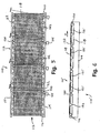
FIG. 1 is a top plan view of a portion of a segmented or zoned belt conveyor in accordance with the present invention; -
FIG. 2 is a side elevation of the portion of the belt conveyor ofFIG. 1 ; -
FIG. 3 is a side elevation of a tracking roller useful with the present invention; -
FIG. 4 is a perspective view of a belt conveyor in accordance with the present invention; -
FIG. 5 is a top plan view of the belt conveyor ofFIG. 4 ; -
FIG. 6 is a side elevation of another belt conveyor in accordance with the present invention; -
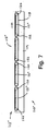
FIG. 7 is a side elevation of another belt conveyor in accordance with the present invention; - Referring now specifically to the drawings and the illustrative embodiments depicted therein, a belt conveyor or
belt accumulator 10 includes one or more zones orsegments 12 positioned along and between opposite sidewalls orside frames 14, and is operable to convey articles in a direction of conveyance A (FIGS. 1 and 2 ). Each segment orzone 12 includes a plurality ofrollers 16 and acontinuous belt 18 routed or reeved around therollers 16. Eachbelted segment 12 may be independently operable to accumulate articles on the segment or zone or to move articles in the direction A onto a next, adjacent segment or zone or onto another conveyor, such as another belt conveyor, a roller conveyor, a slider bed, or the like, or any other means for receiving articles from a discharge end of the last zone or segment of thesegmented belt conveyor 10. As best seen inFIG. 1 ,belt 18 may be wide enough to substantially cover the generally cylindrical roller portions of the rollers and thus may substantially span the spacing between thesidewalls 14 to provide a wide conveying surface for conveying articles along the roller conveyor. -
Rollers 16 of each segment orzone 12 include a motorizedroller 20 and one or more non-motorized oridler rollers 22. Motorizedroller 20 may be the lead roller of the zone or positioned at a downstream end of each segment to pull the belt 18 (and the articles supported thereon) along therespective segment 12. Motorizedroller 20 may comprise a self driven roller with an internal motor which is operable to rotate a roller portion relative to a shaft portion of the roller, such as a motorized roller of the types commercially available from various sources. - For example, the roller may comprise a DC motorized roller, such as a 12 volt DC motorized roller or the like. Optionally, the roller may comprise a 24 volt DC motorized roller or a 42 volt DC motorized roller or a 48 volt DC motorized roller or the like. For example, the motorized roller may comprise a 48 volt DC motorized roller (or a 24 volt DC motorized roller) having a diameter of approximately 50 mm and an overall width of between 500 mm and 900 mm. The 48 volt DC motorized roller may comprise a DC brushless motor and may be operable at speeds between approximately 130 rpm and 1150 rpm and may provide an output of approximately 3 Nm of torque at approximately 400 rpm and approximately 1.5 Nm of torque at approximately 1150 rpm. It is further envisioned that the motorized roller may comprise other DC powered motorized rollers, or may comprise an AC powered motorized roller, without affecting the scope of the present invention. The motor of the motorized roller may drive the roller directly, or may drive the roller via a gear train or the like.
- The
motorized roller 20 thus drives thebelt 18 which moves along theidler rollers 22, which freely rotate about their shaft portions to guide and support thebelt 18 around the zone orsegment 12. Theidler rollers 22 may be any type of rollers, such as conventional, freely rotating rollers, such as the types also commercially available from various sources. Although shown as having multiple idler rollers along each of thezones 12, one or more zones of the segmented belt conveyor of the present invention may include a support plate or slider bed between themotorized roller 20 and an opposite endidler roller 22a to support thebelt 18 between the ends of thezone 12, without affecting the scope of the present invention. - As shown in
FIG. 3 , endidler roller 22a may comprise one or more crowns or bumps 22b along the roller to assist in tracking thebelt 18 during operation of the roller conveyor. The bumps 22b may comprise one or more slightly larger diameter regions of the roller portion, such as two or three regions (or more or less depending on the length of the roller and the particular application) having, for example, approximately a 1-4 mm larger diameter than the diameter of the generally cylindrical portion of the idler roller, which may typically have a diameter of approximately 50 mm. The bumps or crowns may be formed as part of the roller portion or may comprise molded portions, such as molded polyurethane portions or the like, positioned along the roller, without affecting the scope of the present invention. -
Belt 18 may comprise alow modulus belt 18. In the illustrated embodiment,belt 18 has a stretch capability or characteristic of at least approximately 1.5% stretch or more (and may have a stretch capability or characteristic of approximately 3% to 5% stretch or more) in its lengthwise direction.Belt 18 may be initially stretched as it is reeved around the rollers, such that the belt has an initial stretch of approximately 0.75% or more in its lengthwise direction when positioned around the rollers, and may be initially stretched to have an initial stretch of approximately 1% or 1.5%.Belt 18 provides a substantially greater amount of stretch over conventional conveyor belts, which typically may only provide approximately a 1% stretch characteristic or less, and typically may have an initial stretch of approximately 0.25% to 0.5% when reeved or positioned around the pulleys of a conventional belt conveyor.Low modulus belt 18 may be made from urethane extrusions or urethane with polyester or nylon tension members encapsulated or may be made from a rubber material or the like, and may be similar to the type of belts commercially available from Nitta Corporation for use in graphic arts and letter mail sorting. The low modulus characteristic ofbelt 18 and the approximately 0.75% or more initial stretch ofbelt 18 allows eachzone 12 of thebelt conveyor 10 to be operated with little or no take-up or adjustment being necessary to maintain the appropriate tension in thebelt 18. However, such adjustment may be provided onbelt conveyor 10, without affecting the scope of the present invention. - Each zone or
segment 12 may also include a photo eye or sensor (not shown inFIGS. 1 and 2 ) for detecting articles or packages or the like onbelt 18 of the respective zone.Belt conveyor 10 may further include a control for independently operating themotorized roller 20 of the respective zone to move the article alongsegment 12 and/or to temporarily stop the movement of the article or articles to accumulate articles onsegment 12 in response to the sensor and depending on the particular application ofsegmented belt conveyor 10, as discussed in detail below with respect to theconveyor 110 ofFIGS. 3 and 4 . -
Segmented belt conveyor 10 thus may be operable to accumulate articles on one or more of the segments or zones of the conveyor. Optionally, thesegmented belt conveyor 10 may be operable on an incline or decline and may accumulate articles on the incline or decline. It is further envisioned that thesegmented conveyor 10 may be operable to move articles, such as upward along an incline, as the articles are required by a downstream device or system. For example, the belt conveyor of the present invention may convey and feed stacks of trays to a tray destacking apparatus for a tray handling system or the like. The tray destacking apparatus may be operable to receive the stack of trays, separate and unstack each individual tray from the stack of trays and discharge the individual trays to an induct of a tray handling system or tray management system or the like, such as to an induct of a tray handling system at a mail sortation assembly. It is further envisioned that the belt conveyor of the present invention may be used in trailer loader or unloader applications, such as an extendable loader or unloader for extending the conveying surface from a support base outward and into a truck trailer or the like for loading or unloading articles into or out from the trailer, without affecting the scope of the present invention. - Referring now to
FIGS. 4 and5 , a belt conveyor orbelt accumulator 110 includes a plurality of tandem zones orsegments 112 positioned along and between opposite sidewalls or side frames orchannels 114 and is operable to convey articles along each zone in a direction of conveyance A. Eachzone 112 comprises a plurality ofrollers 116 and acontinuous belt 118 routed or reeved around therollers 116. Each beltedzone 112 is independently operable to accumulate articles on the zone or to move articles in the direction A onto a next, adjacent zone or onto another conveyor, such as another belt conveyor, or a roller conveyor, slider bed, or the like, or any other means for receiving articles from a discharge end of the last zone of thebelt conveyor 110. - In the illustrated embodiment of
FIGS. 4 and5 ,conveyor 110 is shown with fivezones 112, with eachzone 112 having amotorized roller 120 and abelt 118 and aproduct sensor 124 positioned at an end of the zone. However, the number of zones along a conveyor section is a function of the application and may vary without affecting the scope of the present invention. - Similar to
rollers 16 ofconveyor 10, discussed above,rollers 116 of each segment orzone 112 include amotorized roller 120 and at least one non-motorized oridler roller 122.Motorized roller 120 may be the lead roller of the zone or may be positioned at a downstream end of each segment to pull the belt 118 (and the articles supported thereon) along therespective zone 112. Similar tomotorized roller 20, discussed above,motorized roller 120 may comprise a self driven roller with an internal motor which is operable to rotate a roller portion relative to a shaft portion of the roller, such as a motorized roller of the types commercially available from various sources, such as a 12 volt DC motorized roller or a 24 volt DC motorized roller or a 42 volt DC motorized roller or a 48 volt DC motorized roller or any voltage AC or DC powered motorized roller or the like. Themotorized roller 120 thus drives therespective belt 118, which moves along theidler rollers 122, which freely rotate about their shaft portions to guide and support thebelt 118 around and along therespective zone 112. Theidler rollers 122 may comprise any type of non-driven rollers, such as conventional, freely rotating rollers or the like, and one or more of the rollers, such as an end idler roller, may include one or more crowns or bumps therealong to assist in tracking the belt, such as discussed above with respect toFIG. 3 . - Although shown as having multiple idler rollers along each of the
zones 112, a zone 112' of a belt conveyor 110' (FIG. 6 ) or azone 112" of abelt conveyor 110" (FIG. 7 ) in accordance with the present invention may optionally include a slider bed between themotorized roller 120 and anidler roller 122 or between a pair of spaced apartidler rollers 122, such as slider bed 121' ofFIG. 6 , or between themotorized roller 120 and an opposite endidler roller 122 or the like, such asslider bed 121" ofFIG. 7 , to support thebelt 118 between the rollers of the zone 112', without affecting the scope of the present invention. The slider bed orbeds 121', 121" may comprise separate plates positioned between two consecutive rollers of a zone or may comprise a plate having a slot or opening therethrough for at least one roller, such as a center roller of the zone, to protrude upward partially through the opening to provide rolling support of the continuous belt along the slider bed, without affecting the scope of the present invention. - As discussed above,
belt 118 may comprise a low modulus belt which may provide for approximately a 0.5% or more initial stretch or more in its lengthwise direction. In an exemplary embodiment, the belt may provide at least approximately a 1.5% to 5% or more stretch capability or characteristic in its lengthwise direction. In an exemplary embodiment,belt 118 may be stretched to have an initial stretch of approximately 1.5% whenbelt 118 is reeved around and positioned around the rollers of the conveyor.Low modulus belt 118 may be made from urethane extrusions or urethane with polyester or nylon tension members encapsulated, or may comprise a rubber material or the like, and may be similar to the type of belts commercially available from Nitta Corporation for use in graphic arts and letter mail sorting. The initial stretch and the low modulus characteristic ofbelt 118 allows eachzone 112 of thebelt conveyor 110 to be operated with little or no take-up or adjustment being necessary to maintain the appropriate tension in thebelt 118. However, such take-up or adjustment may be provided onbelt conveyor 110, without affecting the scope of the present invention. - Each zone or
segment 112 ofconveyor 110 includes a photo eye orarticle sensor 124 for detecting and/or monitoring articles or packages or the like onbelt 118 of the respective zone.Belt conveyor 110 further includes acontrol 126 for independently operating themotorized roller 120 of therespective zone 112 to move the article alongzone 112 and/or to temporarily stop the movement of the article or articles to accumulate articles onzone 112 in response tosensor 124 and depending on the particular application ofsegmented belt conveyor 110. - In the illustrated embodiment,
control 126 comprises a motor control 126a at eachzone 112 which is connected to eachsensor 124 and the other motor controls 126a of the other zones. The motor controls 126a are thus in communication with one another to provide independent and synchronized or corresponding control of the motorized rollers of each zone, as discussed below. The motor controls 126a are connected to a power supply (not shown) which provides power to thesensors 124 and motor controls 126a. The control and photo-eyes may be operable to accumulate articles on the zones of the belt conveyor, and may be operable to individually control operation of at least some of the zones, such as by utilizing accumulating logic and/or circuitry and the like. - In the illustrated embodiment, each
article sensor 124 comprises a photosensor positioned at a downstream end of arespective zone 112 and operable to detect products or articles as they move from the downstream end of one zone to the upstream end of the adjacent zone. The motorized or drivenroller 120 of a particular zone may be selectively activated or deactivated bycontrol 126 in response to acorresponding article sensor 124, or in response to more than one of the article sensors positioned along the conveyor, to move or stop an article or articles that is/are present on the respective zone, as discussed below.Motorized rollers 120 thus may be directly driven and operable to selectively and independently convey or accumulate one or more articles on the associated conveyor zones in response to one or more of thearticle sensors 124. - For example, it is envisioned that the motorized rollers may be operable in a "sleep mode". In such a mode of operation,
control 126 may activate the motorized roller of a particular zone in response to an article being detected at the beginning of the zone (or at the end of the immediate upstream zone) and may deactivate the motorized roller after the article is moved to the next or downstream zone, such that the motorized roller of a particular zone is only activated when an article is present at the zone and when the article is to be conveyed along the zones of the conveyor. If the downstream zones are not activated, then the motorized roller of the particular zone may be deactivated to accumulate the detected article or articles on that particular zone of the conveyor. Such a sleep mode operation thus only activates the motorized roller of a zone when an article to be conveyed is present at the particular zone, and thus reduces operation of the motorized rollers to increase the life cycle of the rollers. - The continuous belts of the belt conveyor of the present invention, and particularly the low modulus belts, may provide an increased coefficient of friction between the conveying or carrying surface of the belts and the products being conveyed therealong over the friction provided by rollers of conventional roller conveyors. The greater frictional resistance to sliding of the articles on the belts allows the belt conveyor of the present invention to operate at a greater speed than roller conveyors, without causing the products to slide along the zones. The greater frictional resistance also enhances the capability of the belt conveyor to move and accumulate articles along each zone individually and to move and accumulate articles on inclined or declined zones.
- The belt conveyor of the present invention thus may be operable to accumulate articles on one or more of the segments or zones of the conveyor. Optionally, the belt conveyor may be operable on an incline or decline and may accumulate articles on the incline or decline. It is further envisioned that the belt conveyor of the present invention may be operable to move articles, such as upward along an incline, as the articles are required by a downstream device or system.
- Therefore, the segmented or zoned belt conveyor of the present invention provides a plurality of independently operable zones or segments which may operate together as a generally continuously running belt conveyor or may operate individually as an accumulating conveyor with zone control and photo eyes. The present invention thus provides a zone controlled belt conveyor which may operate in a similar manner as a zone controlled roller conveyor, but with a continuous belt around the rollers rather than multiple O-rings or the like connecting the idler rollers to the motorized roller of each zone. The segmented belt conveyor of the present invention thus is capable of providing for accumulation of articles on an incline or decline. Because the motorized roller of each zone may only control or drive a small belt section, the load and wear on the motorized roller may be minimized to provide a longer life cycle for the motorized roller.
- Changes and modifications in the specifically described embodiments may be carried out without departing from the principles of the present invention, which is intended to be limited only by the scope of the appended claims.
Claims (15)
- Accumulation conveyor (10, 110, 110', 110") comprising:opposite sidewalls (14, 114);at least two tandem zones (12, 112, 112', 112"), each of said at least two tandem zones (12, 112, 112', 112") comprising:characterized by a continuous belt (18, 118) for conveying articles reeved around said motorized roller (20, 120) and said at least one other roller (22, 22a, 122), said continuous belt (18, 118) of each of said tandem zones (12, 112, 112', 112") comprising a low modulus characteristic, wherein said belt (18, 118) is initially stretched in a lengthwise direction of said belt (18, 118) at least 0.75% when said belt (18, 118) is reeved around said rollers (20, 120, 22, 22a, 122).a motorized roller (20, 120) and at least one other roller (22, 22a, 122) rotatably mounted at and between said opposite sidewalls (14, 114);at least one article sensor (124) operable to detect articles in that zone (12, 112, 112', 112"); andat least one control (126), said at least one control (126) being operable to control said motorized roller (20, 120) of at least one of said zones (12, 112, 112', 112") to drive said belt (18, 198) to convey articles along the respective zone (12, 112, 112', 112"), said at least one control (126) being operable to selectively control said motorized rollers (20, 120) in response to said article sensors (124) to provide accumulation of articles in said zones (12, 112, 112', 112") of said accumulator (10, 110, 110', 110")
- Conveyor of claim 1, wherein said at least one control (126) is operable to control said motorized roller (20, 120) of each of said at least two tandem zones (12, 112, 112', 112") independently from other motorized rollers (20, 120) of other tandem zones (12, 112, 112', 112") to allow for accumulation of articles at one or more of said at least two tandem zones (12, 112, 112', 112").
- Conveyor of claim 1, wherein said belt (18, 118) is initially stretched in a lengthwise direction of said belt (18, 118) at least 1% when said belt (18, 118) is reeved around said rollers (20, 120, 22, 22a, 122).
- Conveyor of claim 1, wherein said belt (18, 118) is initially stretched in a lengthwise direction of said belt (18, 118) at least 1.5% when said belt (18, 118) is reeved around said rollers (20, 120, 22, 22a, 122).
- Conveyor of claim 1, wherein said low modulus characteristic of said belt (18, 118) provides at least a 2% stretch characteristic to said belt (18, 118).
- Conveyor of claim 1, wherein said low modulus characteristic of said belt (18, 118) provides at least a 4% stretch characteristic to said belt (18, 118).
- Conveyor of claim 1, wherein said belt accumulator (10, 110, 110', 110") is positioned at one of an incline or a decline.
- Conveyor of claim 7, wherein said belt accumulator (10, 110, 110', 110") is operable to accumulate articles on said one of an incline or a decline.
- Conveyor of claim 1, wherein said motorized roller (20, 120) of each of said at least two zones (12, 112, 112', 112") comprises one of an AC motor, a 12 volt DC motor, a 24 volt DC motor, a 42 volt DC motor and a 48 volt DC motor.
- Conveyor of claim 1, wherein said motorized roller (20, 120) of each of said at least two zones (12, 112, 112', 112") comprises a 24 volt DC motor.
- Conveyor of claim 1, wherein said motorized roller (20, 120) of each of said at least two zones (12, 112, 112', 112") comprises one of a 42 volt DC motor and a 48 volt DC motor.
- Conveyor of claim 1, wherein at least one of said motorized roller (20, 120) and said at least one other roller (22, 22a, 122) has at least one crown (22b) for tracking said belt (18, 118).
- Conveyor of claim 1, wherein each of said zones (12, 112, 112', 112") includes at least one slider plate (121', 121") between two of said motorized roller (20, 120) and said at least one other roller (22, 22a, 122) for supporting said continuous belt (18, 118) of the respective zone (12, 112, 112', 112") between the two rollers (20, 120, 22, 22a, 122).
- Conveyor of claim 1, wherein each of said zones (12, 112, 112', 112") includes a plurality of spaced apart support rollers (22, 122) supporting said continuous belt (18, 118).
- Conveyor of claim 1, wherein said belt (18, 118) has a width which spans substantially the spacing between said sidewalls (14, 114).
Applications Claiming Priority (5)
| Application Number | Priority Date | Filing Date | Title |
|---|---|---|---|
| US35604502P | 2002-02-11 | 2002-02-11 | |
| US356045P | 2002-02-11 | ||
| US42462902P | 2002-11-07 | 2002-11-07 | |
| US424629P | 2002-11-07 | ||
| PCT/US2003/003819 WO2003068640A1 (en) | 2002-02-11 | 2003-02-07 | Belt conveyor |
Publications (3)
| Publication Number | Publication Date |
|---|---|
| EP1474347A1 EP1474347A1 (en) | 2004-11-10 |
| EP1474347A4 EP1474347A4 (en) | 2005-09-07 |
| EP1474347B1 true EP1474347B1 (en) | 2008-04-02 |
Family
ID=27737515
Family Applications (1)
| Application Number | Title | Priority Date | Filing Date |
|---|---|---|---|
| EP03739711A Revoked EP1474347B1 (en) | 2002-02-11 | 2003-02-07 | Belt conveyor |
Country Status (14)
| Country | Link |
|---|---|
| US (3) | US6811018B2 (en) |
| EP (1) | EP1474347B1 (en) |
| JP (1) | JP2005517608A (en) |
| CN (1) | CN1305743C (en) |
| AT (1) | ATE391096T1 (en) |
| AU (1) | AU2003210926B2 (en) |
| BR (1) | BR0307572A (en) |
| CA (1) | CA2475560C (en) |
| DE (1) | DE60320086T2 (en) |
| DK (1) | DK1474347T3 (en) |
| ES (1) | ES2304520T3 (en) |
| MX (1) | MXPA04007702A (en) |
| NZ (1) | NZ534126A (en) |
| WO (1) | WO2003068640A1 (en) |
Cited By (1)
| Publication number | Priority date | Publication date | Assignee | Title |
|---|---|---|---|---|
| DE102012019717A1 (en) | 2012-10-02 | 2014-04-03 | SSI Schäfer PEEM GmbH | Conveyor system from portable transport modules |
Families Citing this family (71)
| Publication number | Priority date | Publication date | Assignee | Title |
|---|---|---|---|---|
| US6811018B2 (en) * | 2002-02-11 | 2004-11-02 | Rapistan Systems Advertising Corp. | Belt conveyor |
| US7467708B2 (en) * | 2002-02-11 | 2008-12-23 | Dematic Corp. | Belt conveyor and method of converting a roller conveyor to a belt conveyor, and retrofit kit |
| BR0309105A (en) * | 2002-04-12 | 2005-02-01 | Siemens Ag | Curved Belt Conveyor |
| WO2005044701A1 (en) * | 2003-10-28 | 2005-05-19 | Rapistan Systems Advertising Corp. | Flush mounted motorized roller for conveyor |
| US7232029B1 (en) * | 2004-04-14 | 2007-06-19 | Mantissa Corporation | Cantilevered conveying belt for a sortation system |
| US7757842B1 (en) * | 2005-09-26 | 2010-07-20 | Mantissa Corporation | Conveyor belt deck and frame having an substantially vertical maintenance position |
| US7694614B2 (en) * | 2005-12-01 | 2010-04-13 | Walgreen, Co | Case cutter assembly |
| US7720567B2 (en) * | 2005-12-09 | 2010-05-18 | Cornerstone Automation Systems, Inc. | Automated box opening apparatus |
| NL1031094C2 (en) * | 2006-02-07 | 2007-08-08 | Vanderlande Ind Nederland | Transport device. |
| DE102006014454B3 (en) * | 2006-03-29 | 2007-11-08 | Hoffmann, Frank | Punching device with feeding device |
| US7370751B2 (en) * | 2006-05-23 | 2008-05-13 | Dematic Corp. | Skewed slat control system for article conveyor |
| US7806254B2 (en) * | 2006-09-25 | 2010-10-05 | Dematic Corp. | Belt conveyor and method |
| US20080078656A1 (en) * | 2006-10-03 | 2008-04-03 | Dematic Corporation | Curved belt conveyor with autotracking device |
| CA2563645C (en) * | 2006-10-11 | 2011-05-17 | Pierre Laganiere | Extendable conveyor system |
| CA2617093C (en) * | 2007-01-08 | 2017-04-25 | Dematic Corp. | Dynamic singulator |
| US7775346B1 (en) * | 2007-08-07 | 2010-08-17 | Taylor Shirley D | Food buffet table system |
| ATE511942T1 (en) * | 2007-12-13 | 2011-06-15 | Eta Sa Mft Horlogere Suisse | CONVEYOR BELT MODULE |
| US8201681B2 (en) * | 2008-07-14 | 2012-06-19 | Siemens Industry, Inc. | Method for gapping for sortation rate maximization |
| JP5222689B2 (en) * | 2008-10-24 | 2013-06-26 | 伊東電機株式会社 | Conveyor device and conveyor control device |
| US8364307B2 (en) * | 2009-01-09 | 2013-01-29 | Dematic Corp. | Dual power motorized roller |
| AT508328A1 (en) | 2009-06-03 | 2010-12-15 | Tgw Mechanics Gmbh | CONVEYING DEVICE FOR TRANSPORTING GOODS |
| AU2010298016B2 (en) * | 2009-09-28 | 2014-01-16 | Dematic Corp. | Belt drive conveyor with power tap off |
| DE102010001969A1 (en) * | 2010-02-16 | 2011-08-18 | Robert Bosch GmbH, 70469 | Conveyor |
| US20110237169A1 (en) * | 2010-03-26 | 2011-09-29 | Laitram, L.L.C. | Peeler with crowned rollers |
| US8006831B1 (en) | 2010-04-15 | 2011-08-30 | Deere & Company | Multifunction conveyor side extrusions |
| DE102010044027A1 (en) * | 2010-11-17 | 2012-05-24 | Klug Gmbh Integrierte Systeme | Traffic jam system with two communication systems |
| US8950568B2 (en) * | 2011-05-25 | 2015-02-10 | Thyssenkrupp Norte, S.A. | Support, module, transport system for displacement of people/goods and modernization method of people/goods transport systems |
| CN103373488A (en) * | 2012-04-25 | 2013-10-30 | 苏州中德机电装备有限公司 | Collecting and conveying integrated composite conveying system |
| WO2013163692A1 (en) * | 2012-05-01 | 2013-11-07 | Williames Tea Pty Ltd | Improvements to wide belts and wide belt tracking |
| ES2686698T3 (en) | 2012-07-11 | 2018-10-19 | Dematic Corp. | Cross-tape sorting system and article classification method |
| CN102826324A (en) * | 2012-09-19 | 2012-12-19 | 昆山特力伯传动科技有限公司 | Roller-type conveyor |
| CN102951465B (en) * | 2012-10-26 | 2015-06-17 | 天津长荣印刷设备股份有限公司 | Belt correction device and working method thereof |
| US20140224622A1 (en) * | 2013-02-08 | 2014-08-14 | Dematic Corp. | Low rate singulator |
| DE102013206222A1 (en) * | 2013-04-09 | 2014-10-09 | Weber Maschinenbau Gmbh Breidenbach | conveyor system |
| US9409727B2 (en) | 2013-05-31 | 2016-08-09 | Dematic Corp. | Conveyor merge assembly |
| CN103434694B (en) * | 2013-08-29 | 2016-05-18 | 四川首昂科技有限责任公司 | A kind of endowed system of blood and control method |
| US9741009B2 (en) * | 2013-09-09 | 2017-08-22 | Dematic Corp. | Transfer system and material-handling system and method using such transfer system |
| US20150107967A1 (en) * | 2013-10-22 | 2015-04-23 | George W. Horn | High volume conveyor transport for clean environments |
| EP3107844B1 (en) * | 2014-02-19 | 2022-11-16 | Laitram, L.L.C. | Low-energy roller-belt accumulator |
| CN105314331A (en) * | 2015-11-27 | 2016-02-10 | 南通恒康数控机械有限公司 | Anti-slip mechanism for sponge conveying belt |
| CN105795609A (en) * | 2016-04-14 | 2016-07-27 | 温州意迈达鞋业有限公司 | Conveying device for shoemaking machine |
| EP3235764B1 (en) * | 2016-04-18 | 2022-06-29 | BEUMER Group GmbH & Co. KG | Method and apparatus for synchronized feeding of articles onto a sorting conveyor |
| CN106494823A (en) * | 2016-12-05 | 2017-03-15 | 芜湖市元山机械制造有限公司 | A kind of beam welding sub-unit machining set-up of automatic transport |
| CN106829446A (en) * | 2017-01-12 | 2017-06-13 | 东莞松山智能机器人有限公司 | A kind of conveying device and its transmission line body |
| US10093489B2 (en) * | 2017-01-12 | 2018-10-09 | Sweed Machinery, Inc. | Veneer transporting apparatus |
| DE102017002019B4 (en) * | 2017-03-02 | 2022-08-04 | Interroll Holding Ag | Feeding device and method for providing a feeding device |
| CN106946031A (en) * | 2017-04-06 | 2017-07-14 | 建华建材(江苏)有限公司 | A kind of end plate automatic charging device |
| US10351353B1 (en) | 2017-09-28 | 2019-07-16 | Skarlupka Mfg., Inc. | Narrow belt conveyor with 90 degree cross transfer |
| CN107826313A (en) * | 2017-11-08 | 2018-03-23 | 北京博日鸿科技发展有限公司 | A kind of pillow bag blanking device at a high speed |
| US10239696B1 (en) * | 2018-04-06 | 2019-03-26 | Intelligrated Headquarters, Llc | Conveyor cartridge |
| US10669102B2 (en) | 2018-04-06 | 2020-06-02 | Intelligrated Headquarters, Llc | Conveyor axle retainer |
| US11484886B2 (en) * | 2018-05-23 | 2022-11-01 | Vermeer Manufacturing Company | Shredder for comminuting bulk material |
| US11851288B2 (en) * | 2018-09-20 | 2023-12-26 | Körber Supply Chain Llc | System and method for uniform distribution of articles |
| US10787260B2 (en) * | 2018-11-15 | 2020-09-29 | Goodrich Corporation | Above-floor wire routing for an aircraft cargo handling system |
| US11432463B2 (en) | 2019-02-08 | 2022-09-06 | Jackrabbit, Inc. | Nut harvester with a removable assembly and a method of replacing a removable assembly of a nut harvester |
| CN109969675A (en) * | 2019-04-15 | 2019-07-05 | 浙江喜歌实业有限公司 | A kind of storehouse Intelligent logistics conveying device |
| CN110053941B (en) * | 2019-05-27 | 2021-09-28 | 大连海事大学 | Belt conveyor carrier roller abnormal state monitoring system and method based on speed detection |
| WO2020263460A1 (en) * | 2019-06-25 | 2020-12-30 | Ramper Innovations, Inc. | Foldable conveyor system |
| CO2019007406A1 (en) | 2019-07-10 | 2021-01-18 | Compania De Galletas Noel S A S | Roller transmission for mesh traction |
| US11097900B2 (en) * | 2019-08-30 | 2021-08-24 | Intelligrated Headquarters, Llc | Crowned roller with a grooved apex |
| US10858198B1 (en) * | 2019-10-02 | 2020-12-08 | Intelligrated Headquarters, Llc | Singulation conveyor system with rollers of different roller cross-sectional profiles |
| US11981507B2 (en) | 2020-06-03 | 2024-05-14 | Robotica, Inc. | Tote handling system with tote handler and method of using same |
| US11981023B2 (en) | 2020-01-17 | 2024-05-14 | Robotica, Inc. | Tote handling system with integrated hand and method of using same |
| US11407596B1 (en) | 2021-01-29 | 2022-08-09 | Intelligrated Headquarters, Llc | Methods and systems for establishing and transmitting status parameters of a conveyor technological field |
| CN113044468B (en) * | 2021-04-12 | 2022-11-29 | 德利九州物流自动化系统(北京)有限公司 | Conveying equipment and security check system |
| JP7732768B2 (en) * | 2021-04-30 | 2025-09-02 | 株式会社前川製作所 | Meat processing equipment |
| BR102021018108A2 (en) | 2021-09-13 | 2023-03-28 | Freed Participaçoes S/A | CONVEYOR BELT DRIVED BY LINEAR INDUCTION MOTOR WITH DOUBLE-SIDED PRIMARY AND LONG SECTIONED SECONDARY |
| CN114394395A (en) * | 2021-12-02 | 2022-04-26 | 湖南长城计算机系统有限公司 | A conveying system and conveying method |
| CN114368600B (en) * | 2022-03-22 | 2022-08-05 | 杭州杰牌传动科技有限公司 | Logistics conveying optimization control device based on transmission load balance |
| WO2024165600A1 (en) * | 2023-02-08 | 2024-08-15 | Interroll Holding Ag | Roller conveyor arrangement |
| US12497243B2 (en) * | 2023-08-25 | 2025-12-16 | Intelligrated Headquarters, Llc | Strip belt conveyor assembly |
Family Cites Families (53)
| Publication number | Priority date | Publication date | Assignee | Title |
|---|---|---|---|---|
| US3122935A (en) * | 1964-03-03 | Conveyor belt pulley | ||
| US3075630A (en) | 1959-03-09 | 1963-01-29 | Mathews Conveyer Co | Article synchronizing conveyer |
| US3291288A (en) * | 1964-08-31 | 1966-12-13 | Aeroquip Corp | Conveyor belt |
| US3310161A (en) * | 1965-03-31 | 1967-03-21 | Goodyear Tire & Rubber | Turn conveyor |
| US3938313A (en) * | 1967-08-29 | 1976-02-17 | Owens-Corning Fiberglas Corporation | Reinforcement for tires and method of making same |
| US3485339A (en) | 1967-12-11 | 1969-12-23 | Fairbank Morse Inc | Article spacing system |
| US3627108A (en) | 1969-12-04 | 1971-12-14 | Kenneth P Hansen | Angular conveyor |
| US3608703A (en) * | 1970-04-08 | 1971-09-28 | United States Steel Corp | Conveyor belt protection device |
| US3808658A (en) * | 1970-11-27 | 1974-05-07 | Xerox Corp | Snap roller |
| US3722660A (en) * | 1971-11-26 | 1973-03-27 | Snead E Des | Weighing apparatus |
| US3930573A (en) * | 1974-03-29 | 1976-01-06 | Wyard Industries, Inc. | Accumulating conveyor and control means |
| US3995735A (en) | 1974-09-03 | 1976-12-07 | Jos. Schlitz Brewing Company | Conveyor system |
| US3942625A (en) * | 1974-09-13 | 1976-03-09 | Snead Edwin Des | Portable conveyor load measuring apparatus |
| US4061223A (en) * | 1975-09-30 | 1977-12-06 | The First National Bank Of Akron, Trustee | Stretchable belt conveyor |
| US4047444A (en) * | 1976-09-10 | 1977-09-13 | Borg-Warner Corporation | Synchronous belt and pulley drive |
| US4140216A (en) * | 1977-03-09 | 1979-02-20 | Dynaloc Corporation | Track roller having V-shaped helical grooves |
| DE2814436A1 (en) | 1978-04-04 | 1979-10-18 | Albany Int Corp | Conveyor or transmission driving belt - is of rope wound into hose and impregnated with hardened elastomer material |
| FR2425394A1 (en) * | 1978-05-08 | 1979-12-07 | Albany Int Corp | Conveyor or transmission driving belt - is of rope wound into hose and impregnated with hardened elastomer material |
| US4227607A (en) | 1979-04-16 | 1980-10-14 | Malavenda Peter P | High volume method and system for dynamically storing articles for sorting and routing |
| CA1228873A (en) * | 1983-08-08 | 1987-11-03 | Douglas J. Brown | Lug loader |
| GB8603590D0 (en) * | 1986-02-13 | 1986-03-19 | Lucas Ind Plc | Dynamo electric machines |
| EP0324900B1 (en) * | 1988-01-13 | 1990-08-29 | Ferag AG | Method and device for changing the overlapping degree in a stream of printed products |
| US4832186A (en) * | 1988-04-18 | 1989-05-23 | Dynapower Corporation | Conveyor tracking roller having helical guides with variable pitch |
| ATE87588T1 (en) | 1988-07-08 | 1993-04-15 | Mannesmann Ag | ROLLER CONVEYOR. |
| US5070995A (en) * | 1988-09-08 | 1991-12-10 | Mts Systems Corporation | Noncontact conveyor feeder system |
| DE3926735A1 (en) * | 1989-08-12 | 1991-02-21 | Hermann Kronseder | METHOD AND DEVICE FOR FEEDING BOTTLES OR THE LIKE |
| IT1238798B (en) | 1989-10-13 | 1993-09-03 | Stream Srl | APPARATUS TO APPROACH THEM, AT A PREFIXED DISTANCE, PRODUCTS THAT ADVANCE ALONG A CONVEYOR BELT. |
| JPH03267214A (en) | 1990-03-16 | 1991-11-28 | Hitachi Kiden Kogyo Ltd | Object feeding device for conveyor |
| US5083655A (en) * | 1990-12-18 | 1992-01-28 | Omni Technical Services, Inc. | Accumulator conveyor |
| DE4115327A1 (en) | 1991-05-10 | 1992-11-12 | Joerg Henning Bender | Conveyor transport system with number of separate sections - has separate motor drive and controller for each section with sensor inputs and communication between adjacent controllers |
| US5213202A (en) * | 1991-10-07 | 1993-05-25 | Morrison Marketing, Inc. | Helically grooved conveyor pulley for use in belted conveyor systems |
| CN2117356U (en) * | 1992-04-21 | 1992-09-30 | 沈阳煤炭设计研究院 | Belt conveyer with telescopical head |
| JPH06100139A (en) | 1992-09-22 | 1994-04-12 | Daifuku Co Ltd | Article conveying device |
| US5341915A (en) | 1992-11-06 | 1994-08-30 | Kliklok Corporation | Article phasing, transfer and squaring system for packaging line |
| US5285887A (en) | 1992-11-23 | 1994-02-15 | Interroll Holding A. G. | Accumulating conveyor and control system |
| JP2975799B2 (en) | 1993-03-02 | 1999-11-10 | 日立機電工業株式会社 | Article supply control method in sorting machine |
| US5442248A (en) * | 1994-04-11 | 1995-08-15 | Interroll Holding, A.G. | Motorized pulley with integral electrical connector |
| US5582286A (en) | 1994-10-28 | 1996-12-10 | Electrocom Automation, L.P. | Modular power roller conveyor |
| US5620084A (en) * | 1995-03-30 | 1997-04-15 | Jervis B. Webb Company | Chain propelled belt conveyor |
| JPH09183505A (en) | 1995-11-01 | 1997-07-15 | Yokohama Rubber Co Ltd:The | Conveyor belt |
| US5957263A (en) * | 1996-09-25 | 1999-09-28 | Advanced Robotic Technologies, Inc. | Apparatus for correcting for wear of a conveyor belt |
| JPH10236621A (en) | 1997-02-26 | 1998-09-08 | Mitsuboshi Belting Ltd | Carrying belt |
| US6244427B1 (en) * | 1997-09-16 | 2001-06-12 | Motion Systems, L.C. | Modular gearless motorized conveyor roller |
| JPH11165830A (en) | 1997-12-04 | 1999-06-22 | Nippon Steel Corp | Belt conveyor tension controller |
| DE19801823A1 (en) | 1998-01-15 | 1999-07-22 | Mannesmann Ag | General cargo conveyor |
| NL1009142C2 (en) | 1998-05-12 | 1999-11-15 | Oebrabantoe D Van Opstal B V M | Method and device for collecting and discharging relatively light material. |
| US6253906B1 (en) | 1998-05-18 | 2001-07-03 | Milwaukee Electronics Corporation | Sequential release control for a zoned conveyor system |
| US6244421B1 (en) | 1998-05-20 | 2001-06-12 | Milwaukee Electronics Corporation | Singulated release for a zoned conveyor system |
| JP2000038207A (en) | 1998-07-24 | 2000-02-08 | Hitachi Ltd | Belt transport device and paper handling automatic machine |
| JP4175491B2 (en) * | 1999-05-07 | 2008-11-05 | オークラ輸送機株式会社 | Transport device |
| DE20018272U1 (en) | 2000-10-18 | 2001-04-05 | ATECS Mannesmann AG, 40213 Düsseldorf | Belt conveyor for general cargo |
| US6811018B2 (en) * | 2002-02-11 | 2004-11-02 | Rapistan Systems Advertising Corp. | Belt conveyor |
| BR0309105A (en) * | 2002-04-12 | 2005-02-01 | Siemens Ag | Curved Belt Conveyor |
-
2003
- 2003-02-05 US US10/358,690 patent/US6811018B2/en not_active Expired - Lifetime
- 2003-02-07 AU AU2003210926A patent/AU2003210926B2/en not_active Ceased
- 2003-02-07 AT AT03739711T patent/ATE391096T1/en active
- 2003-02-07 DE DE60320086T patent/DE60320086T2/en not_active Expired - Lifetime
- 2003-02-07 CN CNB038036959A patent/CN1305743C/en not_active Expired - Fee Related
- 2003-02-07 DK DK03739711T patent/DK1474347T3/en active
- 2003-02-07 JP JP2003567785A patent/JP2005517608A/en active Pending
- 2003-02-07 CA CA2475560A patent/CA2475560C/en not_active Expired - Fee Related
- 2003-02-07 MX MXPA04007702A patent/MXPA04007702A/en active IP Right Grant
- 2003-02-07 BR BR0307572-9A patent/BR0307572A/en active Search and Examination
- 2003-02-07 WO PCT/US2003/003819 patent/WO2003068640A1/en not_active Ceased
- 2003-02-07 ES ES03739711T patent/ES2304520T3/en not_active Expired - Lifetime
- 2003-02-07 NZ NZ534126A patent/NZ534126A/en not_active IP Right Cessation
- 2003-02-07 EP EP03739711A patent/EP1474347B1/en not_active Revoked
-
2004
- 2004-10-27 US US10/975,199 patent/US7093709B2/en not_active Expired - Lifetime
-
2006
- 2006-08-15 US US11/504,509 patent/US7556144B2/en not_active Expired - Fee Related
Cited By (3)
| Publication number | Priority date | Publication date | Assignee | Title |
|---|---|---|---|---|
| DE102012019717A1 (en) | 2012-10-02 | 2014-04-03 | SSI Schäfer PEEM GmbH | Conveyor system from portable transport modules |
| WO2014053380A1 (en) | 2012-10-02 | 2014-04-10 | SSI Schäfer PEEM GmbH | Conveying equipment system comprising portable transport modules |
| US9561911B2 (en) | 2012-10-02 | 2017-02-07 | SSI Schäfer PEEM GmbH | Conveyor system comprising portable transport modules |
Also Published As
| Publication number | Publication date |
|---|---|
| ATE391096T1 (en) | 2008-04-15 |
| DK1474347T3 (en) | 2008-06-09 |
| AU2003210926A1 (en) | 2003-09-04 |
| ES2304520T3 (en) | 2008-10-16 |
| EP1474347A4 (en) | 2005-09-07 |
| US6811018B2 (en) | 2004-11-02 |
| US20030150695A1 (en) | 2003-08-14 |
| CA2475560C (en) | 2010-10-05 |
| DE60320086D1 (en) | 2008-05-15 |
| CA2475560A1 (en) | 2003-08-21 |
| US7093709B2 (en) | 2006-08-22 |
| WO2003068640A1 (en) | 2003-08-21 |
| CN1630610A (en) | 2005-06-22 |
| NZ534126A (en) | 2005-10-28 |
| DE60320086T2 (en) | 2009-06-04 |
| US20050056524A1 (en) | 2005-03-17 |
| JP2005517608A (en) | 2005-06-16 |
| BR0307572A (en) | 2004-12-21 |
| MXPA04007702A (en) | 2005-09-08 |
| US20060272930A1 (en) | 2006-12-07 |
| US7556144B2 (en) | 2009-07-07 |
| AU2003210926B2 (en) | 2008-06-12 |
| CN1305743C (en) | 2007-03-21 |
| EP1474347A1 (en) | 2004-11-10 |
Similar Documents
| Publication | Publication Date | Title |
|---|---|---|
| AU2003210926B2 (en) | Belt conveyor | |
| US6971510B2 (en) | Curved belt conveyor | |
| US7040480B2 (en) | Zero back pressure conveyor | |
| US6260688B1 (en) | Apparatus for controlling the flow of articles | |
| US7021456B2 (en) | Conveyor roller with brake | |
| US8561790B2 (en) | Belt drive conveyor with power tap off | |
| US7748520B1 (en) | Slip roller conveyor | |
| US6899219B2 (en) | Tape drive conveyor | |
| US11174108B1 (en) | Universal sorter transfer module | |
| MXPA00008034A (en) | Guide conveyor having a laterally adjustable deflector roller at the end |
Legal Events
| Date | Code | Title | Description |
|---|---|---|---|
| PUAI | Public reference made under article 153(3) epc to a published international application that has entered the european phase |
Free format text: ORIGINAL CODE: 0009012 |
|
| 17P | Request for examination filed |
Effective date: 20040712 |
|
| AK | Designated contracting states |
Kind code of ref document: A1 Designated state(s): AT BE BG CH CY CZ DE DK EE ES FI FR GB GR HU IE IT LI LU MC NL PT SE SI SK TR |
|
| AX | Request for extension of the european patent |
Extension state: AL LT LV MK RO |
|
| RIC1 | Information provided on ipc code assigned before grant |
Ipc: 7B 65G 43/00 A Ipc: 7B 65G 43/10 B Ipc: 7B 65G 47/53 B Ipc: 7B 65G 47/26 B Ipc: 7B 65G 15/50 B Ipc: 7B 65G 15/32 B |
|
| A4 | Supplementary search report drawn up and despatched |
Effective date: 20050720 |
|
| 17Q | First examination report despatched |
Effective date: 20060303 |
|
| RAP1 | Party data changed (applicant data changed or rights of an application transferred) |
Owner name: DEMATIC CORP. |
|
| GRAP | Despatch of communication of intention to grant a patent |
Free format text: ORIGINAL CODE: EPIDOSNIGR1 |
|
| GRAS | Grant fee paid |
Free format text: ORIGINAL CODE: EPIDOSNIGR3 |
|
| GRAA | (expected) grant |
Free format text: ORIGINAL CODE: 0009210 |
|
| AK | Designated contracting states |
Kind code of ref document: B1 Designated state(s): AT BE BG CH CY CZ DE DK EE ES FI FR GB GR HU IE IT LI LU MC NL PT SE SI SK TR |
|
| REG | Reference to a national code |
Ref country code: GB Ref legal event code: FG4D |
|
| REG | Reference to a national code |
Ref country code: CH Ref legal event code: EP Ref country code: IE Ref legal event code: FG4D |
|
| REF | Corresponds to: |
Ref document number: 60320086 Country of ref document: DE Date of ref document: 20080515 Kind code of ref document: P |
|
| REG | Reference to a national code |
Ref country code: DK Ref legal event code: T3 |
|
| REG | Reference to a national code |
Ref country code: CH Ref legal event code: NV Representative=s name: PA ALDO ROEMPLER |
|
| REG | Reference to a national code |
Ref country code: CH Ref legal event code: PCAR Free format text: ALDO ROEMPLER PATENTANWALT;BRENDENWEG 11 POSTFACH 154;9424 RHEINECK (CH) |
|
| PG25 | Lapsed in a contracting state [announced via postgrant information from national office to epo] |
Ref country code: SI Free format text: LAPSE BECAUSE OF FAILURE TO SUBMIT A TRANSLATION OF THE DESCRIPTION OR TO PAY THE FEE WITHIN THE PRESCRIBED TIME-LIMIT Effective date: 20080402 |
|
| REG | Reference to a national code |
Ref country code: ES Ref legal event code: FG2A Ref document number: 2304520 Country of ref document: ES Kind code of ref document: T3 |
|
| PG25 | Lapsed in a contracting state [announced via postgrant information from national office to epo] |
Ref country code: FI Free format text: LAPSE BECAUSE OF FAILURE TO SUBMIT A TRANSLATION OF THE DESCRIPTION OR TO PAY THE FEE WITHIN THE PRESCRIBED TIME-LIMIT Effective date: 20080402 Ref country code: BG Free format text: LAPSE BECAUSE OF FAILURE TO SUBMIT A TRANSLATION OF THE DESCRIPTION OR TO PAY THE FEE WITHIN THE PRESCRIBED TIME-LIMIT Effective date: 20080702 Ref country code: PT Free format text: LAPSE BECAUSE OF FAILURE TO SUBMIT A TRANSLATION OF THE DESCRIPTION OR TO PAY THE FEE WITHIN THE PRESCRIBED TIME-LIMIT Effective date: 20080903 |
|
| ET | Fr: translation filed | ||
| PLBI | Opposition filed |
Free format text: ORIGINAL CODE: 0009260 |
|
| PG25 | Lapsed in a contracting state [announced via postgrant information from national office to epo] |
Ref country code: SE Free format text: LAPSE BECAUSE OF FAILURE TO SUBMIT A TRANSLATION OF THE DESCRIPTION OR TO PAY THE FEE WITHIN THE PRESCRIBED TIME-LIMIT Effective date: 20080702 Ref country code: CZ Free format text: LAPSE BECAUSE OF FAILURE TO SUBMIT A TRANSLATION OF THE DESCRIPTION OR TO PAY THE FEE WITHIN THE PRESCRIBED TIME-LIMIT Effective date: 20080402 |
|
| PLAX | Notice of opposition and request to file observation + time limit sent |
Free format text: ORIGINAL CODE: EPIDOSNOBS2 |
|
| 26 | Opposition filed |
Opponent name: SSI SCHAEFER PEEM GMBH Effective date: 20081219 |
|
| PG25 | Lapsed in a contracting state [announced via postgrant information from national office to epo] |
Ref country code: SK Free format text: LAPSE BECAUSE OF FAILURE TO SUBMIT A TRANSLATION OF THE DESCRIPTION OR TO PAY THE FEE WITHIN THE PRESCRIBED TIME-LIMIT Effective date: 20080402 Ref country code: BE Free format text: LAPSE BECAUSE OF FAILURE TO SUBMIT A TRANSLATION OF THE DESCRIPTION OR TO PAY THE FEE WITHIN THE PRESCRIBED TIME-LIMIT Effective date: 20080402 |
|
| NLR1 | Nl: opposition has been filed with the epo |
Opponent name: SSI SCHAEFER PEEM GMBH |
|
| PG25 | Lapsed in a contracting state [announced via postgrant information from national office to epo] |
Ref country code: EE Free format text: LAPSE BECAUSE OF FAILURE TO SUBMIT A TRANSLATION OF THE DESCRIPTION OR TO PAY THE FEE WITHIN THE PRESCRIBED TIME-LIMIT Effective date: 20080402 |
|
| PLBB | Reply of patent proprietor to notice(s) of opposition received |
Free format text: ORIGINAL CODE: EPIDOSNOBS3 |
|
| PG25 | Lapsed in a contracting state [announced via postgrant information from national office to epo] |
Ref country code: MC Free format text: LAPSE BECAUSE OF NON-PAYMENT OF DUE FEES Effective date: 20090228 Ref country code: CY Free format text: LAPSE BECAUSE OF FAILURE TO SUBMIT A TRANSLATION OF THE DESCRIPTION OR TO PAY THE FEE WITHIN THE PRESCRIBED TIME-LIMIT Effective date: 20080402 |
|
| PG25 | Lapsed in a contracting state [announced via postgrant information from national office to epo] |
Ref country code: IE Free format text: LAPSE BECAUSE OF NON-PAYMENT OF DUE FEES Effective date: 20090209 |
|
| PG25 | Lapsed in a contracting state [announced via postgrant information from national office to epo] |
Ref country code: GR Free format text: LAPSE BECAUSE OF FAILURE TO SUBMIT A TRANSLATION OF THE DESCRIPTION OR TO PAY THE FEE WITHIN THE PRESCRIBED TIME-LIMIT Effective date: 20080703 |
|
| PG25 | Lapsed in a contracting state [announced via postgrant information from national office to epo] |
Ref country code: LU Free format text: LAPSE BECAUSE OF NON-PAYMENT OF DUE FEES Effective date: 20090207 |
|
| APAH | Appeal reference modified |
Free format text: ORIGINAL CODE: EPIDOSCREFNO |
|
| APBM | Appeal reference recorded |
Free format text: ORIGINAL CODE: EPIDOSNREFNO |
|
| APBP | Date of receipt of notice of appeal recorded |
Free format text: ORIGINAL CODE: EPIDOSNNOA2O |
|
| PG25 | Lapsed in a contracting state [announced via postgrant information from national office to epo] |
Ref country code: HU Free format text: LAPSE BECAUSE OF FAILURE TO SUBMIT A TRANSLATION OF THE DESCRIPTION OR TO PAY THE FEE WITHIN THE PRESCRIBED TIME-LIMIT Effective date: 20081003 |
|
| APBQ | Date of receipt of statement of grounds of appeal recorded |
Free format text: ORIGINAL CODE: EPIDOSNNOA3O |
|
| PG25 | Lapsed in a contracting state [announced via postgrant information from national office to epo] |
Ref country code: TR Free format text: LAPSE BECAUSE OF FAILURE TO SUBMIT A TRANSLATION OF THE DESCRIPTION OR TO PAY THE FEE WITHIN THE PRESCRIBED TIME-LIMIT Effective date: 20080402 |
|
| PLCK | Communication despatched that opposition was rejected |
Free format text: ORIGINAL CODE: EPIDOSNREJ1 |
|
| REG | Reference to a national code |
Ref country code: FR Ref legal event code: PLFP Year of fee payment: 13 |
|
| PGFP | Annual fee paid to national office [announced via postgrant information from national office to epo] |
Ref country code: NL Payment date: 20150218 Year of fee payment: 13 |
|
| PGFP | Annual fee paid to national office [announced via postgrant information from national office to epo] |
Ref country code: DE Payment date: 20150219 Year of fee payment: 13 Ref country code: DK Payment date: 20150218 Year of fee payment: 13 Ref country code: IT Payment date: 20150224 Year of fee payment: 13 Ref country code: ES Payment date: 20150225 Year of fee payment: 13 Ref country code: CH Payment date: 20150218 Year of fee payment: 13 |
|
| PGFP | Annual fee paid to national office [announced via postgrant information from national office to epo] |
Ref country code: GB Payment date: 20150218 Year of fee payment: 13 Ref country code: FR Payment date: 20150219 Year of fee payment: 13 Ref country code: AT Payment date: 20150219 Year of fee payment: 13 |
|
| PLAB | Opposition data, opponent's data or that of the opponent's representative modified |
Free format text: ORIGINAL CODE: 0009299OPPO |
|
| R26 | Opposition filed (corrected) |
Opponent name: SSI SCHAEFER PEEM GMBH Effective date: 20081219 |
|
| REG | Reference to a national code |
Ref country code: DE Ref legal event code: R064 Ref document number: 60320086 Country of ref document: DE Ref country code: DE Ref legal event code: R103 Ref document number: 60320086 Country of ref document: DE |
|
| APBU | Appeal procedure closed |
Free format text: ORIGINAL CODE: EPIDOSNNOA9O |
|
| RDAF | Communication despatched that patent is revoked |
Free format text: ORIGINAL CODE: EPIDOSNREV1 |
|
| RDAG | Patent revoked |
Free format text: ORIGINAL CODE: 0009271 |
|
| STAA | Information on the status of an ep patent application or granted ep patent |
Free format text: STATUS: PATENT REVOKED |
|
| REG | Reference to a national code |
Ref country code: CH Ref legal event code: PLX |
|
| 27W | Patent revoked |
Effective date: 20150811 |
|
| GBPR | Gb: patent revoked under art. 102 of the ep convention designating the uk as contracting state |
Effective date: 20150811 |
|
| PG25 | Lapsed in a contracting state [announced via postgrant information from national office to epo] |
Ref country code: LI Free format text: LAPSE BECAUSE OF THE APPLICANT RENOUNCES Effective date: 20080402 Ref country code: CH Free format text: LAPSE BECAUSE OF THE APPLICANT RENOUNCES Effective date: 20080402 |
|
| REG | Reference to a national code |
Ref country code: AT Ref legal event code: MA03 Ref document number: 391096 Country of ref document: AT Kind code of ref document: T Effective date: 20150811 |