The present invention relates to lithographic apparatus and device manufacturing
methods using lithographic apparatus.
A lithographic apparatus is a machine that applies a desired pattern onto a target
portion of a substrate. Lithographic apparatus can be used, for example, in the manufacture
of integrated circuits (ICs). In that circumstance, a patterning means, such as a mask, may
be used to generate a circuit pattern corresponding to an individual layer of the IC, and this
pattern can be imaged onto a target portion (e.g. comprising part of, one or several dies) on
a substrate (e.g. a silicon wafer) that has a layer of radiation-sensitive material (resist). In
general, a single substrate will contain a network of adjacent target portions that are
successively exposed. Known lithographic apparatus include so-called steppers, in which
each target portion is irradiated by exposing an entire pattern onto the target portion in one
go, and so-called scanners, in which each target portion is irradiated by scanning the pattern
through the projection beam in a given direction (the "scanning"-direction) while
synchronously scanning the substrate parallel or anti-parallel to this direction.
A pellicle is a thin, transparent film that is attached by a frame to the chrome side
of a mask or reticle used in lithography. The pellicle and its frame keep the space near the
chrome of the mask free of dust particles. In this way, any dust particles near the mask are
kept away from the best object plane and will thus be imaged out of focus and will not
cause defects. However, the standard pellicle material, a polymer film, can not be used
when 157nm radiation is used as the exposure radiation. The polymer film is not
transparent to this wavelength and the exposure radiation would deteriorate the optical
properties of the pellicle.
Therefore, a new pellicle material that is suitable for 157nm radiation has been
sought. The best solution found so far is to use fluorine-doped quartz. This is an inorganic
material. In order to use it as a pellicle, the pellicle thickness has to be substantially
increased, e.g. to 800µm. Because the pellicle material has a different refractive index than
the surrounding gas, such a thick pellicle causes imaging effect which cannot be neglected.
The main effect is an observed object plane shift. From behind the pellicle the
object appears to be closer than it actually is. With an 800µm thick pellicle that has a
refractive index of 1.5, the observed object plane shift is about 280µm. Because the object
appears to have moved towards the projection system, this can be corrected by moving the
mask stage away from the projection lens by about 280 µm. However, any deviations from
planarity or in thickness of the pellicle will introduce other aberrations which will have
undesirable effects on imaging.
It is an object of the present invention to provide lithographic projection apparatus
and device manufacturing methods in which the effects of a thick pellicle can be
compensated for or ameliorated.
According to an aspect of the invention there is provided a lithographic projection
apparatus comprising:
characterized by:
- a storage device adapted to store information relating to the physical and/or optical
characteristics of said layer;
- a controller adapted to control at least one of said projection system, said radiation
system, said substrate table and said support structure in response to information stored in
said storage device to compensate for or ameliorate imaging aberrations caused by said
layer other than a displacement of the apparent mask position along the optical axis of the
apparatus.
Rather than attempting to make a pellicle that is sufficiently flat and of uniform
thickness and optical properties that its effects on imaging of the mask are within
acceptable limits, the present invention accepts that the pellicle will introduce aberrations
and compensates for or ameliorates them by adjusting other parts of the apparatus. For
example, certain aberrations, such as spherical aberrations and magnification errors
(especially in the non-scanning direction), caused by the pellicle may be compensated for
by adjusting elements in the projection system. Others, such as image translations and
magnification errors in the scanning direction may be compensated for by control of the
mask and substrate table positions during an exposure or adjusting other parts of the
apparatus.
The information relating to physical and/or optical properties of the pellicle may
include data relating to the thickness and refractive index variations across its area, as well
as its three-dimensional shape, in particular local tilt values. Alternatively, the information
may comprise corrections to be applied in an exposure that are pre-calculated from such
data.
The properties of the pellicle may be measured by an off-line tool such as an
interferometer, especially a Fourier transform phase shift interferometer, in which case the
apparatus preferably further provides an interface for receiving said information in
conjunction with the loading of a mask into the apparatus. The interface may comprise a
network interface device for receiving the information via a network in the fab or a
removable media reader for reading the information from a data carrier accompanying the
mask. With such an arrangement, the characterization of the pellicle and calculation of
corrections can be carried out as thoroughly as necessary without increasing the time taken
for changing masks and hence with no reduction in throughput.
Alternatively, the apparatus may be provided with a suitable image sensor, such as
a transmission image sensor or white light interferometer, and the controller may be further
adapted to control the sensor and/or the mask table to characterize the pellicle in situ. In
this way, the possibility of error caused by changes in the pellicle shape between off-line
characterization and use for exposures is reduced.
According to a further aspect of the invention there is provided a device
manufacturing method comprising the steps of:
- providing a substrate that is at least partially covered by a layer of radiation-sensitive
material;
- providing a projection beam of radiation using a radiation system;
- using a mask having a pellicle in spaced relation thereto to endow the projection
beam with a pattern in its cross-section;
- projecting the patterned beam of radiation onto a target portion of the layer of
radiation-sensitive material,
characterized in that:
- in said step of projecting, corrections are applied to at least one of the radiation
system, the projection system, the position of the mask and the position of the substrate to
compensate for or ameliorate aberrations other than a shift in apparent position of the mask
in the direction of the optical axis of said projection system caused by said pellicle, said
corrections having been determined from information relating to the physical and/or optical
characteristics of said pellicle.
According to yet a further aspect of the invention there is provided a mask having
a pellicle fixed to a frame in spaced relation thereto, wherein said pellicle is fixed to said
frame along two parallel edges and compliantly mounted along the other edges such that
said pellicle adopts a one-dimensional shape when in the orientation in which it will be
used for exposures in a lithographic projection apparatus.
Because it is fixed along two opposite edges only, the pellicle will adopt under the
influence of gravity a predictable shape which results in a predictable image displacement
(error) which can be corrected for during exposures. The error can also be easily measured
using an image sensor such as a transmission image sensor.
Although specific reference may be made in this text to the use of lithographic
apparatus in the manufacture of ICs, it should be understood that the lithographic apparatus
described herein may have other applications, such as the manufacture of integrated optical
systems, guidance and detection patterns for magnetic domain memories, liquid-crystal
displays (LCDs), thin-film magnetic heads, etc. The skilled artisan will appreciate that, in
the context of such alternative applications, any use of the terms "wafer" or "die" herein
may be considered as synonymous with the more general terms "substrate" or "target
portion", respectively. The substrate referred to herein may be processed, before or after
exposure, in for example a track (a tool that typically applies a layer of resist to a substrate
and develops the exposed resist) or a metrology or inspection tool. Where applicable, the
disclosure herein may be applied to such and other substrate processing tools. Further, the
substrate may be processed more than once, for example in order to create a multi-layer IC,
so that the term substrate used herein may also refer to a substrate that already contains
multiple processed layers.
The terms "radiation" and "beam" used herein encompass all types of
electromagnetic radiation, including ultraviolet (UV) radiation (e.g. having a wavelength of
365, 248, 193, 157 or 126 nm) and extreme ultra-violet (EUV) radiation (e.g. having a
wavelength in the range of 5-20 nm).
The term "patterning means" used herein should be broadly interpreted as
referring to means that can be used to impart a projection beam with a pattern in its cross-section
such as to create a pattern in a target portion of the substrate. It should be noted that
the pattern imparted to the projection beam may not exactly correspond to the desired
pattern in the target portion of the substrate. Generally, the pattern imparted to the
projection beam will correspond to a particular functional layer in a device being created in
the target portion, such as an integrated circuit.
Patterning means may be transmissive or reflective. Examples of patterning means
include masks, programmable mirror arrays, and programmable LCD panels. Masks are
well known in lithography, and include mask types such as binary, alternating phase-shift,
and attenuated phase-shift, as well as various hybrid mask types. An example of a
programmable mirror array employs a matrix arrangement of small mirrors, each of which
can be individually tilted so as to reflect an incoming radiation beam in different directions;
in this manner, the reflected beam is patterned. In each example of patterning means, the
support structure may be a frame or table, for example, which may be fixed or movable as
required and which may ensure that the patterning means is at a desired position, for
example with respect to the projection system. Any use of the terms "reticle" or "mask"
herein may be considered synonymous with the more general term "patterning means".
The term "projection system" used herein should be broadly interpreted as
encompassing various types of projection system, including refractive optical systems,
reflective optical systems, and catadioptric optical systems, as appropriate for example for
the exposure radiation being used, or for other factors such as the use of an immersion fluid
or the use of a vacuum. Any use of the term "lens" herein may be considered as
synonymous with the more general term "projection system".
The illumination system may also encompass various types of optical components,
including refractive, reflective, and catadioptric optical components for directing, shaping,
or controlling the projection beam of radiation, and such components may also be referred
to below, collectively or singularly, as a "lens".
The lithographic apparatus may be of a type having two (dual stage) or more
substrate tables (and/or two or more mask tables). In such "multiple stage" machines the
additional tables may be used in parallel, or preparatory steps may be carried out on one or
more tables while one or more other tables are being used for exposure.
The lithographic apparatus may also be of a type wherein the substrate is
immersed in a liquid having a relatively high refractive index, e.g. water, so as to fill a
space between the final element of the projection system and the substrate. Immersion
liquids may also be applied to other spaces in the lithographic apparatus, for example,
between the mask and the first element of the projection system. Immersion techniques are
well known in the art for increasing the numerical aperture of projection systems.
Embodiments of the invention will now be described, by way of example only,
with reference to the accompanying schematic drawings in which:
In the Figures, corresponding reference symbols indicate corresponding parts.
Embodiment 1
Figure 1 schematically depicts a lithographic apparatus according to a particular
embodiment of the invention. The apparatus comprises:
- an illumination system (illuminator) IL for providing a projection beam PB of
radiation (e.g. UV radiation or DUV radiation).
- a first support structure (e.g. a mask table) MT for supporting patterning means
(e.g. a mask) MA and connected to first positioning means PM for accurately positioning
the patterning means with respect to item PL;
- a substrate table (e.g. a wafer table) WT for holding a substrate (e.g. a
resist-coated wafer) W and connected to second positioning means PW for accurately
positioning the substrate with respect to item PL; and
- a projection system (e.g. a refractive projection lens) PL for imaging a pattern
imparted to the projection beam PB by patterning means MA onto a target portion C (e.g.
comprising one or more dies) of the substrate W.
As here depicted, the apparatus is of a transmissive type (e.g. employing a
transmissive mask). Alternatively, the apparatus may be of a reflective type (e.g. employing
a programmable mirror array of a type as referred to above).
The illuminator IL receives a beam of radiation from a radiation source SO. The
source and the lithographic apparatus may be separate entities, for example when the
source is an excimer laser. In such cases, the source is not considered to form part of the
lithographic apparatus and the radiation beam is passed from the source SO to the
illuminator IL with the aid of a beam delivery system BD comprising for example suitable
directing mirrors and/or a beam expander. In other cases the source may be integral part of
the apparatus, for example when the source is a mercury lamp. The source SO and the
illuminator IL, together with the beam delivery system BD if required, may be referred to
as a radiation system.
The illuminator IL may comprise adjusting means AM for adjusting the angular
intensity distribution of the beam. Generally, at least the outer and/or inner radial extent
(commonly referred to as σ-outer and σ-inner, respectively) of the intensity distribution in
a pupil plane of the illuminator can be adjusted. In addition, the illuminator IL generally
comprises various other components, such as an integrator IN and a condenser CO. The
illuminator provides a conditioned beam of radiation, referred to as the projection beam
PB, having a desired uniformity and intensity distribution in its cross-section.
The projection beam PB is incident on the mask MA, which is held on the mask
table MT. Having traversed the mask MA, the projection beam PB passes through the lens
PL, which focuses the beam onto a target portion C of the substrate W. With the aid of the
second positioning means PW and position sensor IF (e.g. an interferometric device), the
substrate table WT can be moved accurately, e.g. so as to position different target portions
C in the path of the beam PB. Similarly, the first positioning means PM and another
position sensor (which is not explicitly depicted in Figure 1) can be used to accurately
position the mask MA with respect to the path of the beam PB, e.g. after mechanical
retrieval from a mask library, or during a scan. In general, movement of the object tables
MT and WT will be realized with the aid of a long-stroke module (coarse positioning) and
a short-stroke module (fine positioning), which form part of the positioning means PM and
PW. However, in the case of a stepper (as opposed to a scanner) the mask table MT may be
connected to a short stroke actuator only, or may be fixed. Mask MA and substrate W may
be aligned using mask alignment marks M1, M2 and substrate alignment marks P1, P2.
The depicted apparatus can be used in the following preferred modes:
Combinations and/or variations on the above described modes of use or entirely
different modes of use may also be employed.
Figure 2 shows a mask MA which comprises a transparent, e.g. quartz, substrate
11 on one face of which is provided a chrome pattern 12 representing the pattern which is
to be printed on a substrate. A frame 13 surrounds the chrome pattern and supports a
pellicle 14 in spaced relation to the mask MA. The pellicle 14 is a thin, transparent
membrane that protects the chrome pattern and in particular prevents dust particle settling
on the chrome pattern. Frame 13 is sized so that the pellicle is spaced from the plane of the
chrome pattern 12 by a distance d, e.g. about 5mm, sufficient that any dust particle
adhering to the pellicle is out of focus during an exposure and does not print in the resist on
the substrate.
The pellicle must be made of a material that is transparent to the exposure
radiation and should be as thin as possible; mechanical considerations (including pellicle
dynamics such as acoustic vibrations, scan speed-induced deformation, etc.) determine the
minimum thickness of the pellicle. For exposure radiation at 157nm, polymer materials
used at longer wavelengths are insufficiently transparent and would absorb energy from the
projection beam rapidly enough to deteriorate. A pellicle for 157nm can be made of
fluorine-doped quartz but for mechanical reasons must have a thickness of about 800µm.
Due to this thickness, the pellicle introduces a shift in the Z direction (parallel to the optical
axis of the projection system) of the apparent position of the chrome pattern or, looking at
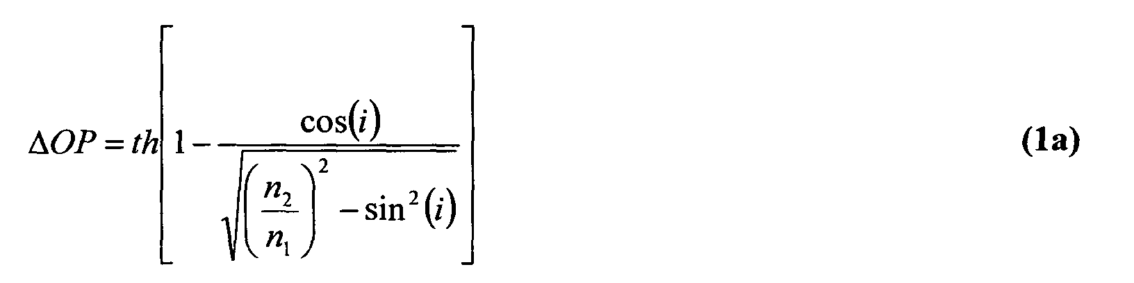
it another way, in the best focal plane. Using Snell's law, this shift
ΔOP is given by:
or equivalently:
where
th is the thickness of the pellicle,
n1 is the refractive index of the
surrounding medium (air, vacuum or flushing gas)
n2 is the refractive index of the pellicle,
i is the angle of the beam in the surrounding medium (determined by the illumination
settings NA and σ) and
r the angle of the beam in the pellicle.
Further, if the pellicle is locally non-parallel to the mask, there will be an apparent
distortion of the pattern,
dr, given by:
The resulting distortion of the projected image at substrate level is reduced by the
magnification, M (e.g. 1/4), of the projection system and is given by:
These effects are illustrated in Figure 3.
According to the present invention, the pellicle shape and thickness are measured
and the imaging effects (e.g. distortion (shape), defocus (thickness)) introduced by the
shape and thickness are corrected for. In general, pellicle deformation (local tilt) results in
an image displacement (distortion). The pellicle thickness (variation) is of importance to
obtain the best object plane. In order to reduce the induced distortion and focus errors
system adjustments are applied. The benefit of performing these adjustments (or better
measuring or predicting the pellicle shape) is that the specifications put on the pellicle
shape can be relaxed while giving comparable overlay and focus performance to a perfectly
flat pellicle. Thus each pellicle is individually measured and corrected for, providing
additional flexibility.
In the first embodiment of the invention, the pellicle shape is measured using an
off-line tool such as an interferometer. The measured pellicle shape can be used to
calculate several system corrections such as translation (x and y), magnification (Mx), scan
scaling (My), etc.. It is also possible to determine symmetric rotation (scan skew and lens
rotation) (pellicle shape = f(x*y)) introduced by the pellicle. Furthermore, the thickness
(variation) can be measured using the interferometer which can be used to determine the
shift in best object plane with respect to the case when no pellicle is present. These
correctables are fed into the system to accommodate for the pellicle shape.
By way of an example, the shape and thickness of a pellicle was measured using a
Zygo VeriFire MST 1550 (TM) FTPSI (Fourier Transform Phase Shift Interferometer) tool.
The Zygo tool is a precision interferometric optical system that can be used to measure the
distances between several surfaces, optical path lengths, refractive indices, etc.. The
measured shape was described using a polynomial fit and the fitting parameters were
translated into system correctables. In other words, the measured pellicle shape is described
as a function of (x, y, x.y, x2, y2, x4, x6, etc.) and then transformed into a function of
(translation x, translation y, symmetric rotation (scan skew and lens rotation),
Magnification y, Magnification x, third order distortion, fifth order distortion, etc.).
Using the information of the measured pellicle shape the distortion induced by the
pellicle was calculated and is shown in Figure 4. This distortion plot was used to calculate
several system correctables. The validity of the calculated correctables were
experimentally verified - see Table 1 and Figure 5 which shows close agreement with
Figure 4.
| Correctable | Calculated value Zygo measurement | Measured value using dynamic distortion test |
| Translation x [nm] | -8.69 | -7.56 (σ 2.67) |
| Translation y [nm] | 19.07 | 20.62 (σ 3.18) |
| Scan skew [µrad] | -0.31 | -0.39 (σ 0.04) |
| Magnification x* [ppm] | 0.79 | 0.94 (σ 0.12) |
| Magnification y* [ppm] | 0.20 | 0.20 (σ 0.09) |
The dynamic distortion test is a standard test to measure the image displacement
(overlay performance).
Embodiment 2
In a second embodiment of the invention, which is otherwise the same as the first
embodiment, the pellicle shape, thickness, etc. is measured using a tool in the lithographic
apparatus. There are two variants to this embodiment, the first using a white light
interferometer and the second using a plurality of image sensor (TIS) measurements.
In the first variant of the second embodiment, a White Light Interferometer (WLI)
is used to measure the pellicle shape and thickness. With this method information is
obtained for the whole pellicle area. Using this shape the system adjustments can be
calculated and implemented to correct for overlay errors caused by pellicle deformation and
shift in best object plane by the pellicle thickness (as described above).
Commercially available White Light Interferometers are capable of accurately
measuring the absolute height of an optical surface. By scanning the mask, with pellicle
attached, through the WLI beam(s) full field information of the pellicle shape is obtained.
A WLI may already be provided in the lithographic apparatus for use in set-up and
calibration of the mask stage.
In the second variant of the second embodiment, the pellicle shape is locally
probed using a Transmission Image Sensor (TIS sensor), a sensor which detects an image
projected by the lithographic apparatus, making use of the exposure wavelength and
illumination settings. The TIS measurement is performed through the pellicle. A multi-point
TIS measurement can be used to determine for each point best focus, image
translation and other aberrations (e.g. spherical). A precondition for using this method is
that pellicle shape is predetermined within certain boundaries. If the pellicle shape is
relatively simple, relatively few measurements can be sufficient to predict the pellicle
shape. Thus, the necessary corrections can be done based on a limited number of
measurements. In a third embodiment, described below, the pellicle shape is made more
predictable. Only localized field information (for a limited number of field points) is
needed to predict the pellicle shape and thus the system correctables. The standard TIS
measurement (determination of x, y and z) through a pellicle only provides information
about the pellicle global tilt resulting in an image translation. Additional TIS HAPVAP
(horizontal (x) aligned position - vertical (y) aligned position) measurements provide in
information about the shift in Best Object Plane (BOP), and hence the shift in the plane of
best focus. If the pellicle has a one-dimensional shape, multi-point TIS measurements can
be used to measure this shape and correct not only for translation but also for
magnification, third order distortion and possibly other imaging effects (e.g. aberration
control).
The concept of multi-point TIS measurements is not only beneficial for applying
pellicle corrections but has much more broader applicability. In general this method can be
used to correct for reticle deformations causing focus and overlay errors. Currently, four
point reticle alignment information, derived using the TIS is used to correct for focus, Ry-image-tilt,
Rx-scan-tilt and linear roll (corkscrew) during an exposure. However, also large
defocus contributors appear to be present in the higher orders of reticle curvature e.g.
quadratic wedge and field curvature. To correct for these, the higher order shape of the
reticle (in z) must be known. This can be achieved by providing additional alignment
marks on the reticle along the scanning and/or slit direction. So applying the concept of
multiple TIS (>4) measurements, for example, the multi-point information in the scanning
direction can be used to obtain information on quadratic scan tilt (Q-wedge) and other
higher orders in z in the scan direction. Whereas the multi-point information in the slit
direction can be used to correct for pellicle (one-dimensional pellicle bow through the slit)
and/or reticle deformation, a fit of the accumulated z-data is used to feed-forward correct
for the height of the reticle and/or, when applicable, pellicle shape during a scan. The
reticle height is corrected on the reticle table and pellicle effects are corrected using several
system adjustables (e.g. lens elements, reticle table height, focus (at wafer level)). The
above described concept of multi-point TIS measurements can be used independently of
the pellicle characterization and can significantly reduce the reticle shape contribution to
the focus budget regardless of the flatness degree of the reticle.
Embodiment 3
In a third embodiment of the invention, in addition to the pellicle characterization
used in the first and second embodiments, the shape of the pellicle is controlled so as to
make its effects more easily correctable.
Previously, the aim in mounting pellicle has been to mount the pellicle to the mask
so that the pellicle is perfectly flat. In other words, curvature of the pellicle and wedge of
the pellicle are minimized. In order to achieve this, gravity compensation (to control
curvature) and careful pellicle grinding and polishing (to control wedge) are applied. The
pellicle sag caused by gravity is counteracted by applying a pellicle pre-shape when
attaching the pellicle to the pellicle frame. This pre-shaping aims to ensure that when the
mask with pellicle is used, the pellicle is perfectly flat.
However, in this embodiment, a controlled substantially one-dimensional pellicle
shape/deformation is provided. The pellicle has a known curvature in one direction, along
the illumination field or in the scan direction, and a substantially constant cross-section in
the perpendicular direction a small amount of curvature in the perpendicular direction may
remain but is preferably minimised. The benefit with respect to gravity compensation is
that now the pellicle shape has to be controlled in one dimension instead of two. This is
technically less challenging and much easier to achieve. The one-dimensional pellicle
shape along the slit or scan direction is then compensated for by applying system
corrections. It is often simplest to correct pellicle sag in the scan (y) direction, but it is also
possible to correct sag in the orthogonal (x) direction. Using beam deflection formulas (see
for example Applied Strength of Materials, Robert L Mott 3rd Ed 1996 ISBN 0-13-376278-5,
which document is hereby incorporated in its entirety by reference), the values for first
and third order distortion (and other pellicle induced imaging effects) are obtained. The
derivative of the deflection formula is directly, apart from a constant, related to the pellicle
induced image displacement so that the pellicle-induced image displacement can be
estimated.
Below, three examples are described showing that one-dimensional pellicle
deformation can be described with a second and fourth order equation resulting in a first
(magnification) and third order distortion. A fourth example deals with more complex
pellicle shapes that induce an image distortion that can be corrected for using system
variables. It is noted that in the below-described examples for clarity the global pellicle tilt
is taken equal to zero. In general a tilt would result in an image translation which can be
automatically corrected (using for example the results of known alignment processes).
In the first example, instead of applying gravity compensation to the pellicle, the
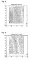
pellicle bending in the slit is the same as bending caused by gravity, as shown in Figure 6.
The pellicle is attached to the frame at two parallel edges so that the tilt of the pellicle
equals that of a pellicle that is supported at the edges and bends freely due to gravity. So
the pellicle is fixed at the edges at an angle α that equals the angle of free beam deflection
(Figure 6). The pellicle deflection y(x) is given by:
where
w [N/m] is the applied force due to gravity per length unit,
x [m] the pellicle
(beam) position,
L [m] the pellicle (beam) length,
E [Pa] Young's modulus and
I [m
4] the
moment of inertia. Using the data presented in Table 2 the pellicle deflection through the
slit and the corresponding bending angle for a 800 µm thick fluorine-doped quartz pellicle
can be evaluated, as shown in Figure 7.
| Pellicle Material Properties |
| Material property | Value |
| Young's modulus (E) | 73 | [GPa] |
| Poisson's ratio (v) | 0.16 | [-] |
| Density (ρ) | 2.20 ± 0.01 | [g cm-3] |
| Pellicle refractive Index @ 157.6 nm (n2 ) | 1.67 | [-] |
| Gas refractive Index @ 157.6 nm (n1 ) | 1.00 | [-] |
| Gravitation constant (g) | 9.8 | [m/s2] |
| Pellicle length (L) | 12.4 | [cm] |
| Pellicle thickness (th) | 800 | [µm] |
| Pellicle width (b) | 14.9 | [cm] |
| Gravity induced force per pellicle length (w) | g·(L·b·th)·ρ/L | [N/m] |
| Moment of inertia (I) | 1 / 12·b·th3 | [m4] |
It can be seen that
w·L I = g · L · ρ 112 · th 2
For this purpose the formula for the beam deflection was rewritten changing the
point
x = 0 from the edge of the pellicle to the center. This is done because the derivative of
the pellicle deflection viz. the bending angle is proportional (with factor
th (1-
n2 /
n1 )) to the
induced image distortion (M, D2, D3 etc.) which can than directly be derived from the
pellicle deflection (distortion is described from the center of the slit). The pellicle
deflection and corresponding angle is then given by:
and
This gives the following expression for the distortion
d(xw) at wafer level due to
pellicle bending:
where
xw [m] the slit position at wafer level (
xw =
x/4),
th [m] the pellicle
thickness,
n1 [-] is the refractive index of the gas mixture surrounding the pellicle,
n2 [-] is
the refractive index of the pellicle,
M [nm/mm] is the pellicle-induced magnification and
D3 [nm/cm
3] the third order distortion. Using this description is it directly clear that the
pellicle deflection can be written using only even powers of
x resulting in odd powers of
x
for the deflection angle and thus also for the distortion. Odd distortion terms in particular
can be easily automatically corrected in the current lithographic apparatus making
distortion correction for a one-dimensional predefined pellicle shape possible. For this
case it can be easily shown that:
and
Using the values given in table 2 above, these equations give a magnification M of
3.416 ppm and a third order distortion D3 of -4.740 nm/cm3 for a 800 µm pellicle at 157
nm.
From which it is clear that distortion is not necessarily a limiting factor for using a
non-flat pellicle. Assuming that the Zemike coefficients for a deflected reticle scale with
the pellicle thickness variation in z the induced additional aberrations with respect to the
perfect pellicle case are negligible.
In the second example, the pellicle is fixed to the frame so that the angle of tilt in
the scan direction at the frame is zero. This arrangement is shown in Figure 8.
For such an arrangement the pellicle deflection
y(
x) is given by (see reference
above):
y(x) = -w ·x 2·(L - x)2 24E · I
in which the constants and variables are as defined above. The pellicle bending
amount and angle are shown in Figure 9. Again, the formula for the beam deflection was
rewritten changing the point x = 0 from the edge of the pellicle to the center. This is done
because the derivative of the pellicle deflection with respect to the bending angle is
proportional (with factor
th (1-
n2 /
n1 )) to the induced image distortion (M, D2, D3 etc.),
which can than directly be derived from the pellicle deflection (distortion is described from
the center of the slit). The pellicle deflection and corresponding angle are then given by:
and
This results for the distortion
d(xw) at wafer level due to pellicle bending in:
Again, the pellicle deflection can be written using only even powers of x resulting
in odd powers of
x for the deflection angle and thus also for the distortion. Odd distortion
terms in particular can be easily automatically corrected in current lithographic apparatus
making distortion correction for a one-dimensional predefined pellicle shape possible. For
this case it can be easily shown that:
and
Using the values given in table 2 above, these equations give a magnification M of
1.139 ppm and a third order distortion D3 of -4.740 nm/cm3 for a 800 µm pellicle at 157
nm.
Again it is clear that distortion is not necessarily a limiting factor for using a non-flat
pellicle. Assuming that the Zernike coefficients for a deflected pellicle scale with the
pellicle sag induced thickness variation in z the induced additional aberrations with respect
to the perfect pellicle case are negligible.
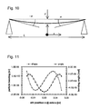
In the third example, the pellicle is fixed to the frame at an arbitrary angle α. This
arrangement is shown in Figure 10.
By shifting the point
x = 0 to the center of the pellicle the pellicle deflection and
corresponding angle are given by:
and
This results for the distortion
d(
xw ) at wafer level due to pellicle bending in:
Note that only the magnification term depends on the starting angle α and not the
D3 term. This implies that when a pellicle has a one-dimensional shape a standard
alignment process on four markers would be sufficient to obtain the magnification
correction (irrespective of the applied α), provided it is adapted to accommodate the
pellicle-induced D3 term. The D3 term is known from the standard beam deflection
formulas or alternately can be found by using finite element calculations.
From the above formulae, the optimum mounting angle which results in the
smallest maximum observed pellicle tilt can be determined and is given by:
This optimum mounting angle equals also the maximum observed pellicle tilt and
results in the minimum image displacement. Using the data as presented in table 2 above,
an optimum angle α of -55 µrad is obtained. The pellicle deflection and tilt for this
mounting angle are shown in Figure 11. It can also be shown that:
and
Using the values given in table 2 above, these equations give a magnification M of
0.854 ppm and a third order distortion D3 of -4.740 nm/cm3 for a 800 µm pellicle at 157
nm.
The three examples discussed above address pellicle curvature in the illumination
slit. However, the same equations can be applied to pellicle curvature in the scan direction,
simply with a change in value of L.
In a fourth example, a more complex pellicle shape is employed. In general, the
shape of a given pellicle can be expressed as a function of x and y, S(x,y), given by:
S(x,y) = c + tx · x + ty · y + mx · x 2 +my · y 2 + symrot · (xy) + d3 x · x 4 + NCE(x,y)dxdy
where the fitting parameters tx, ty, mx, my , symrot, d3 x and NCE(x, y) are related to
the system parameters translation x, translation y, magnification x, magnification y,
symmetric rotation (scan skew and lens rotation), 3rd order distortion in x and Non-Correctable
Error in overlay, respectively.
Presented with a pellicle of arbitrary shape, two approaches are possible. In both,
the shape is represented in the form of equation (23) and values for the fitting parameters
are determined, then used during exposures to apply corrections. In the first approach, the
values of the fitting parameters are chosen using a least squares fit to minimize the value of
the non-correctable error NCE(x,y)dxdy over the whole of the imaging field. An alternative
approach is to select the fitting parameters so that the largest value of NCE(x,y)dxdy in the
imaging field is as small as possible. Other optimization criteria can also be employed.
For example, the pellicle shape can be optimized to minimize image fading.
Image fading occurs when magnification and third order distribution corrections
are applied to account for a substantially one-dimensional pellicle shape. The corrections
are applied to account for the pellicle-induced effects in the slit direction (perpendicular to
the scan direction) but introduce errors in the scan direction. These errors will average out
to zero due to the scan but instead cause image fading due to the fact that the apparent
feature position varies during a scan. The amount of image fading is dependent on the
moving standard deviation (MSD) of a field point during a scan. In general imaging fading
is not a problem provided the MSD is less than 10% of the relevant feature size. An
optimum angle for the pellicle mount can be calculated to minimize image fading and may
be negative i.e. the pellicle centre is closer to the mask than are the edges. A limit of MSD
<10 to 20% of the critical dimension may be used to define an allowable range of pellicle
mounting angle.
Alternatively, equation 23 can be used in designing a shape for a pellicle. Rather
than being constrained to the simple forms of the earlier examples, the pellicle shape can be
a linear combination of correctible shapes, that is shapes leading to distortions that are
correctable by available control parameters of the lithographic apparatus. In other words,
the pellicle shape can be any shape satisfying the equation:
S(x,y) = c + tx · x + ty · y + mx · x 2 + my · y 2 + symrot · (xy) + d3 x · x 4
Note of course that the exact form of this equation will depend on the available
system parameters of a given lithographic projection apparatus that can be used to adjust
for pellicle induced distortion. Also corrections for pellicle-induced distortions may be
combined with corrections for other factors.
Once a pellicle shape has been determined, it must be mounted to the mask in
such a manner that the desired shape is adopted in use and also a sealed enclosure for the
mask pattern is made, to prevent particle contamination of the mask pattern. Several
approaches to this can be taken.
Firstly, the frame for the pellicle can be ground to, otherwise formed in, the shape
that the pellicle is designed to adopt so that a seal around the whole perimeter can be made.
Secondly, where the pellicle is to be supported along two edges only, an
upstanding rim or flange can be provided along the non-supporting edges of the frame so
that it is very close to, but not touching, the edge of the pellicle. Such a rim may also be
shaped to act as a spoiler to reduce scan-speed dependent forces on the pellicle (e.g.
deriving from Bernoulli effects) that may alter its shape. Of course, such forces may also
be taken into account when determining the expected shape the pellicle will adopt in use
and hence the corrections to be applied.
Thirdly, with the pellicle in the shape that it is to adopt in use, sealing material can
be introduced into any gaps between the frame and pellicle, e.g. by a capillary infiltration
technique.
Example
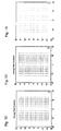
Figures 12, 13 and 14 illustrate an example of the invention. A sample pellicle
mounted to have a one dimensional shape with angle 0° at the edges is determined to give
rise to the distortions shown in Figure 12. Using appropriate system correctables, a
compensating distortion as shown in Figure 13 is applied. The resulting net distortion in
the aerial image is considerably reduced, virtually eliminated, as shown in Figure 14.
Embodiment 4
In a fourth embodiment of the invention, arrangements are made to compensate
for Bernoulli effects which may distort the pellicle during a scan.
In a lithographic apparatus that performs scanning exposures, the speed of
movement of the mask table may be very high due to the fact that the mask is 4 or 5 times
larger that the wafer, and hence moves 4 or 5 times faster, and the need to have a high
throughput. Velocities of the order of 0.6ms-1 have been calculated to cause small, but
acceptable deformations of the pellicle. However the effects are proportional to the square
of the scan speed so that an increase in scan speed to 2ms-1 will give a tenfold increase in
the pressure differences across the pellicle.
Because the pressure difference varies at different points over the area of the
pellicle this leads to distortion of the pellicle that is velocity dependent. Various measures
may be taken to ameliorate or compensate for the resulting image effects.
First of all, the pellicle frame may be provided with, or shaped to have the effect
of, a spoiler or spoilers that minimize pressure differences across the pellicle. Spoiler(s)
may also or instead be attached to the mask, the pellicle or the mask table. Secondly, the
purge gas system may be arranged so that there is a flow of purge as parallel to and in the
same sense as the scan velocity. This may entail a reversal of the purge gas flow between
scans in opposite senses. If the purge gas flow is with the mask table scan movement, the
relative velocity of the table through the atmosphere is reduced and so therefore the
Bernoulli effects. Thirdly, the effect of the pellicle shape changes during a scan during an
scan or the projected image may be calculated or measured in advance and appropriate
corrections made in the same way as with other pellicle effects.
Embodiment 5
In a fifth embodiment of the invention problems that may be caused in the process
of mounting the pellicle to the mask are addressed.
Above, it was shown that overlay errors caused by the pellicle, if its shape is
suitably controlled, are proportional to Ax + Bx3 and are correctable via adjustment of
magnification and third order distortion. However, if the origin of the coordinate system of
the pellicle is displaced from that of the mask, additional terms arise and the image
displacement becomes proportional to z1(x), where:
Z1 (x) = (-2Ac + 4Bc3 ) + 2(A + 6Bc2)x + 3(-4Bc)x2 + 4(B)x3
in which c is the displacement of the pellicle origin relative to the mask origin. These
additional terms can result in non-correctable overlay errors.
Further errors may also arise if the mounting angles of the pellicle at its two edges
are not the same. Such a situation leads to a non-symmetric pellicle shape but this can be
represented by a formula of the form Z' (x) = Ax2 + Bx4 with a displaced origin.
In this embodiment, the above problems can be minimized by correct
displacement of the pellicle to the mask. Accordingly, the pellicle shape is measured
before and/or during the mounting process. An optimum position for the pellicle is
calculated - the optimum position may be the position that minimizes image displacements
or minimizes non-correctable image displacements - and the pellicle is fixed to the mask at
the optimum position.
Measurement of the pellicle shape can be performed, for example, by Fourier
transform phase shifting interferometry. Suitable alignment marks, e.g. as known in the art
of lithography, are provided on the pellicle and mask and adjustment of the two can then be
performed with known techniques.
Embodiment 6
In a sixth embodiment of the invention, the mask is replaced by a programmable
patterning means (also referred to as a spatial light modulator) such as a programmable
mirror array on a programmable LCD array (sometimes referred to as a light valve). More
information on suitable programmable mirror arrays can be found in US 5,296,891, US
5,523,193, WO 98/38597 and WO 98/33096 and on suitable LCD arrays in US 5,229,872,
which documents are hereby incorporated by reference.
The programmable patterning means, especially if a programmable mirror array, is
very sensitive to dust and other contaminants and so is housed in a box or package into
which it can be mounted and used in the lithographic apparatus still sealed. The projection
beam enters and leaves the package through one or more windows which are substantially
transparent to the radiation of the projection beam but, being of non-negligible thickness
and having a refractive index different than the surrounding medium, are likely to introduce
undesirable optical effects. At least the effects of the window downstream of the
programmable patterning means are characterized and compensated for in the same manner
as in the first to fifth embodiments described above.
Whilst specific embodiments of the invention have been described above, it will
be appreciated that the invention may be practiced otherwise than as described. For
example, whilst the invention has been described in relation to a chromed mask, it is of
course applicable to other types of mask including chromeless and other types of phase-shifting
mask. Furthermore, the invention may be applied to this or soft pellicles and other
imaging effects caused by an imperfect plan parallel plate, e.g. the liquid film used in
immersion lithography. For immersion lithography the wafermap and the shape of the
immersion lens element can be used compensate for the shape of the immersion medium.
The invention may also be applied to pellicles other than adjacent the mark; for example in
EUV a pellicle may be employed between the substrate and projection lens to protect the
projection lens from contamination emitted by the resist. In general the imaging effects
scale with thickness. For relatively thick pellicles (such as the 800 µm hard pellicle) it is
clear that corrections need to be applied, considering only the shift in best object plane.
However, the described correction strategies are not limited to hard pellicles but also
applicable for thin pellicles or even other parallel plates in the optical path such as a liquid
film. Also it should be noted that although the examples deal with pellicle deformation in
the illumination field, also (one-dimensional) deformation in the scan direction are
correctable by using, for example, the scan speed as correctable. Furthermore, whilst the
invention has been described above in relation to exposure wavelengths that necessitate the
use of a thick or hard pellicle, such particles. Such pellicles and the invention may of
course be used at exposure wavelengths for which thin or soft pellicles are available. A
hard pellicle may be preferred in such cases because it will be less susceptible to Bernoulli
effects, may be reused and may be cleanable. The description is not intended to limit the
invention.