EP1473570A1 - Wälzager mit integrierter Geschwindigkeitsmessvorrichtung - Google Patents
Wälzager mit integrierter Geschwindigkeitsmessvorrichtung Download PDFInfo
- Publication number
- EP1473570A1 EP1473570A1 EP04291087A EP04291087A EP1473570A1 EP 1473570 A1 EP1473570 A1 EP 1473570A1 EP 04291087 A EP04291087 A EP 04291087A EP 04291087 A EP04291087 A EP 04291087A EP 1473570 A1 EP1473570 A1 EP 1473570A1
- Authority
- EP
- European Patent Office
- Prior art keywords
- housing
- bearing
- radial
- directed towards
- axis
- Prior art date
- Legal status (The legal status is an assumption and is not a legal conclusion. Google has not performed a legal analysis and makes no representation as to the accuracy of the status listed.)
- Withdrawn
Links
Images

Classifications
-
- H—ELECTRICITY
- H02—GENERATION; CONVERSION OR DISTRIBUTION OF ELECTRIC POWER
- H02K—DYNAMO-ELECTRIC MACHINES
- H02K5/00—Casings; Enclosures; Supports
- H02K5/04—Casings or enclosures characterised by the shape, form or construction thereof
- H02K5/16—Means for supporting bearings, e.g. insulating supports or means for fitting bearings in the bearing-shields
- H02K5/173—Means for supporting bearings, e.g. insulating supports or means for fitting bearings in the bearing-shields using bearings with rolling contact, e.g. ball bearings
- H02K5/1732—Means for supporting bearings, e.g. insulating supports or means for fitting bearings in the bearing-shields using bearings with rolling contact, e.g. ball bearings radially supporting the rotary shaft at both ends of the rotor
-
- F—MECHANICAL ENGINEERING; LIGHTING; HEATING; WEAPONS; BLASTING
- F16—ENGINEERING ELEMENTS AND UNITS; GENERAL MEASURES FOR PRODUCING AND MAINTAINING EFFECTIVE FUNCTIONING OF MACHINES OR INSTALLATIONS; THERMAL INSULATION IN GENERAL
- F16C—SHAFTS; FLEXIBLE SHAFTS; ELEMENTS OR CRANKSHAFT MECHANISMS; ROTARY BODIES OTHER THAN GEARING ELEMENTS; BEARINGS
- F16C35/00—Rigid support of bearing units; Housings, e.g. caps, covers
- F16C35/04—Rigid support of bearing units; Housings, e.g. caps, covers in the case of ball or roller bearings
- F16C35/042—Housings for rolling element bearings for rotary movement
- F16C35/045—Housings for rolling element bearings for rotary movement with a radial flange to mount the housing
-
- F—MECHANICAL ENGINEERING; LIGHTING; HEATING; WEAPONS; BLASTING
- F16—ENGINEERING ELEMENTS AND UNITS; GENERAL MEASURES FOR PRODUCING AND MAINTAINING EFFECTIVE FUNCTIONING OF MACHINES OR INSTALLATIONS; THERMAL INSULATION IN GENERAL
- F16C—SHAFTS; FLEXIBLE SHAFTS; ELEMENTS OR CRANKSHAFT MECHANISMS; ROTARY BODIES OTHER THAN GEARING ELEMENTS; BEARINGS
- F16C35/00—Rigid support of bearing units; Housings, e.g. caps, covers
- F16C35/04—Rigid support of bearing units; Housings, e.g. caps, covers in the case of ball or roller bearings
- F16C35/06—Mounting or dismounting of ball or roller bearings; Fixing them onto shaft or in housing
- F16C35/07—Fixing them on the shaft or housing with interposition of an element
- F16C35/077—Fixing them on the shaft or housing with interposition of an element between housing and outer race ring
-
- F—MECHANICAL ENGINEERING; LIGHTING; HEATING; WEAPONS; BLASTING
- F16—ENGINEERING ELEMENTS AND UNITS; GENERAL MEASURES FOR PRODUCING AND MAINTAINING EFFECTIVE FUNCTIONING OF MACHINES OR INSTALLATIONS; THERMAL INSULATION IN GENERAL
- F16C—SHAFTS; FLEXIBLE SHAFTS; ELEMENTS OR CRANKSHAFT MECHANISMS; ROTARY BODIES OTHER THAN GEARING ELEMENTS; BEARINGS
- F16C41/00—Other accessories, e.g. devices integrated in the bearing not relating to the bearing function as such
- F16C41/007—Encoders, e.g. parts with a plurality of alternating magnetic poles
-
- G—PHYSICS
- G01—MEASURING; TESTING
- G01P—MEASURING LINEAR OR ANGULAR SPEED, ACCELERATION, DECELERATION, OR SHOCK; INDICATING PRESENCE, ABSENCE, OR DIRECTION, OF MOVEMENT
- G01P3/00—Measuring linear or angular speed; Measuring differences of linear or angular speeds
- G01P3/42—Devices characterised by the use of electric or magnetic means
- G01P3/44—Devices characterised by the use of electric or magnetic means for measuring angular speed
- G01P3/443—Devices characterised by the use of electric or magnetic means for measuring angular speed mounted in bearings
-
- F—MECHANICAL ENGINEERING; LIGHTING; HEATING; WEAPONS; BLASTING
- F16—ENGINEERING ELEMENTS AND UNITS; GENERAL MEASURES FOR PRODUCING AND MAINTAINING EFFECTIVE FUNCTIONING OF MACHINES OR INSTALLATIONS; THERMAL INSULATION IN GENERAL
- F16C—SHAFTS; FLEXIBLE SHAFTS; ELEMENTS OR CRANKSHAFT MECHANISMS; ROTARY BODIES OTHER THAN GEARING ELEMENTS; BEARINGS
- F16C19/00—Bearings with rolling contact, for exclusively rotary movement
- F16C19/02—Bearings with rolling contact, for exclusively rotary movement with bearing balls essentially of the same size in one or more circular rows
- F16C19/04—Bearings with rolling contact, for exclusively rotary movement with bearing balls essentially of the same size in one or more circular rows for radial load mainly
- F16C19/06—Bearings with rolling contact, for exclusively rotary movement with bearing balls essentially of the same size in one or more circular rows for radial load mainly with a single row or balls
-
- F—MECHANICAL ENGINEERING; LIGHTING; HEATING; WEAPONS; BLASTING
- F16—ENGINEERING ELEMENTS AND UNITS; GENERAL MEASURES FOR PRODUCING AND MAINTAINING EFFECTIVE FUNCTIONING OF MACHINES OR INSTALLATIONS; THERMAL INSULATION IN GENERAL
- F16C—SHAFTS; FLEXIBLE SHAFTS; ELEMENTS OR CRANKSHAFT MECHANISMS; ROTARY BODIES OTHER THAN GEARING ELEMENTS; BEARINGS
- F16C2380/00—Electrical apparatus
- F16C2380/26—Dynamo-electric machines or combinations therewith, e.g. electro-motors and generators
-
- H—ELECTRICITY
- H02—GENERATION; CONVERSION OR DISTRIBUTION OF ELECTRIC POWER
- H02K—DYNAMO-ELECTRIC MACHINES
- H02K11/00—Structural association of dynamo-electric machines with electric components or with devices for shielding, monitoring or protection
Definitions
- the present invention relates to the field of bearings with instrumented bearing fitted with a detection assembly rotation parameters, such as angular position, direction of rotation, speed, acceleration, etc.
- This type of bearing is often used in electric motors.
- An electric motor generally comprises a rotor mounted at rotation in a stator thanks to two bearings generally of the type rigid ball and steel rings, arranged at each end of the tree.
- the inner rings of the bearings are mounted on the shaft with a tight fit, while the outer rings are arranged in housings in the motor housing.
- the housing is generally made of a light alloy, for example based aluminum or magnesium.
- an outer ring of one of the two bearings is immobilized axially in its housing by suitable means, such as circlips and / or shoulder and is optionally mounted with clamping in the housing, while the outer ring of the other bearing must be able to move axially slightly relative to the housing.
- the other bearing is often mounted free in its housing.
- the axial distance separating the second bearing from the first bearing which is axially fixed relative to the housing is susceptible to vary slightly.
- the second bearing must therefore be capable of move very slightly in the axial direction with respect to its housing without affecting the proper functioning of the assembly.
- the motor bearings which are generally mounted in light alloy housings based on aluminum or magnesium do not undergo the same dimensional variations as housing. This results in a radial clearance of the ring not rotating relative to its housing and risks of slipping in rotation of said non-rotating ring relative to said housing.
- Document FR-A-2 824 367 describes an assembly comprising an instrumented bearing and a housing associated by a part fitting, in particular for a steering motor of vehicle.
- a bearing is incapable of supporting significant axial loads without backlash or deterioration of the system due to the fragility of the ring which supports the sensor, elastic tabs, and the fitting part of the rolling.
- the invention provides a rolling bearing device instrumented able to withstand high axial loads and large temperature variations.
- the present invention proposes to remedy the disadvantages mentioned above.
- the present invention provides a bearing device for particularly economical and rigid instrumented bearing.
- the instrumented rolling device comprises a bearing provided with a rotating ring and a non-rotating ring, a sensor block mounted integral with the non-rotating ring, and a housing housing said bearing and said block sensor.
- Said housing comprises two radial portions directed one towards the axis of the device and the other towards the outside, and a portion tubular connecting said radial portions, the sensor block being in contact with a bore in the tubular portion.
- the radial portion directed outwards forms a means of axial positioning and fixing the device on a support.
- the radial portion directed towards the axis of the device forms an axial positioning means and axial immobilization of the bearing in the housing.
- the radial portions can be arranged at ends opposite of the tubular portion.
- the housing therefore allows fixing rigid device on a support for a wide range of temperature.
- the radial portion directed towards the axis of the device at least partially covers a lateral face of the non-rotating ring of the bearing for efficient immobilization and not exerting a torsional force on the outer ring.
- the radial portion directed towards the axis of the device at least partially covers the radial space between the bearing rings.
- Said radial portion can form a seal by narrow passage with the rotating ring of the bearing.
- We assure thus sealing one side of the rolling elements so particularly economical.
- the presence of a rubbing lip seal is possible but not essential.
- the absence of a joint allows also to do without seal fixing grooves in one of the rings, resulting in additional savings.
- the outer ring therefore has a rectangular cross section except for the Raceway.
- said radial portion is in contact with a radial face of the non-rotating ring, thus ensuring its axial positioning and its axial immobilization in one direction.
- the immobilizer axial of the bearing and the sensor block in the housing is ensured in a direction by the radial portion directed towards the axis of the device and in the other direction by a weld between the housing and the sensor block.
- the welding can be carried out in a bead on the periphery of the sensor block.
- the weld may include a continuous bead. Alternatively, the weld bead may be discontinuous.
- the axial immobilization of the bearing and the sensor block in the housing is provided in one direction by the radial portion directed towards the axis of the device and in the other direction by a deformation of the housing.
- the deformation can be obtained by knurling. Such deformation which is economical to obtain, also ensures mutual maintenance extremely rigid non-rotating bearing ring and housing.
- the deformation of the housing can be in contact with the periphery of the sensor block.
- the deformation of the case can be continuous or discontinuous.
- the sensor block and the outer ring are in contact by radial surfaces capable of transmitting axial forces important. The sensor block and the outer ring are therefore fixed firmly to the case.
- the sensor block includes a peripheral metal portion in contact with the non-rotating bearing ring.
- the sensor block comprises a flange of protection and closure rigidly fixed on a peripheral part of said sensor block.
- the flange can be in the form of a disc provided with tubular flanges and ensures sealing by passage close to the area near the sensor.
- the sensor block includes a card printed circuit supporting at least one sensor element and maintained in place by a flange.
- the sensor block comprises a ring forming an axial shim between the non-rotating ring and the fixing means formed by the deformation or the weld bead of the housing.
- the bearing is immobilized axially in direction by the inner radial portion of the housing, in the other direction by the cooperation of the sensor unit and the fixing means forming part of the housing.
- the invention also provides an electric motor comprising a housing, a stator, a rotor and a rolling device instrumented comprising a bearing provided with a rotating ring secured to the rotor, a non-rotating ring secured to the housing, a block sensor mounted integral with the non-rotating ring, and a housing housing said bearing and said sensor block.
- the case includes two radial portions directed one towards the axis of the device and the other towards the outside, and a tubular portion connecting said portions radials.
- the radial portion directed towards the outside forms a means of axial positioning and fixing of the device on the casing.
- the radial portion directed towards the axis of the device forms a means of axial positioning and axial immobilization of the bearing in the housing.
- Such an electric motor can be constructed so economical while being able to withstand axial loads large and large temperature variations.
- the radial portion directed towards the outside is fixed to the housing, for example by screwing. This removes the game axial between the housing and the housing.
- the radial portion directed towards the exterior may be in contact with a radial surface of the housing in view of a good transmission of axial forces.
- the axial clearance between the non-rotating ring and the case is removed by the connection axial obtained by welding or by deformation of the housing.
- An encoder ring can be provided, supported by the ring rotating bearing while having a small air gap with the sensor.
- the encoder ring can be of the multipolar magnetic type.
- the absence of axial play between the bearing and the encoder ring guarantees a constant air gap and therefore a reliable sensor output signal.
- the rolling device forms a compact unit easy to install in a housing. It is possible to expand the manufacturing tolerances of the housing of the housing, the ring not bearing rotation not being fitted directly into the casing but through the sheet metal housing.
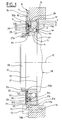
- bearing 1 includes a non-rotating outer ring 2 provided on its bore 2a of a toroidal raceway 3, an inner ring rotating 4 provided on its outer surface 4a with a path toroidal bearing 5, and a row of rolling elements 6, here balls, arranged between the raceway 3 of the outer ring 2 and the raceway 5 of the inner ring 4.
- the elements rollers 6 are maintained at regular circumferential spacings by a cage 7 made of synthetic material.
- the cage can be metallic. Of course, we could use marbles instead rollers or needles.
- the inner 4 and outer 2 rings massive, are obtained by conventional machining of a blank in steel, and have excellent rigidity. For reasons of axial compactness, the outer ring is shorter axially than the inner ring 4, but higher radially.
- the outer ring 2 is provided with two lateral surfaces radial 2b, 2c opposite and a cylindrical outer surface 2d.
- the outer ring 2 is devoid of joint fixing grooves.
- the inner ring 4 is also provided with a bore 4d and two radial lateral surfaces 4b, 4c opposite, the lateral surface 4c being in the same radial plane as the radial surface 2c and a bore 4d.
- the outer ring 2 is arranged in a casing 8 of form general ring, made of stamped sheet steel, and comprising a outer radial portion 9, a tubular portion 10 and a portion inner radial 11.
- the outer radial portion 9 is arranged at a end of the tubular portion 10 and extends outwards, while that the inner radial portion 11 is disposed at the opposite end of the tubular portion 10 and extends in the direction of the geometric axis 12 of the device.
- the outer surface 2d of the outer ring 2 is in contact with the tubular portion 10 and the radial surface 2c is in contact with the inner radial portion 11.
- the outer ring 2 is thus positioned relative to the housing 8 and axially immobilized in a meaning.
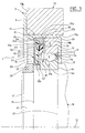
- Said inner radial portion 11 extends beyond the ring outer 2 towards the inner ring 4 with which it forms a narrow passage sealing the bearing on one side rolling elements 6.
- the radial portion interior 11 largely closes the radial annular space between the outer surface 4a of the inner ring 4 and the bore 2a of the outer ring 2.
- the housing 8 is fixed to a support such as a motor housing 13 electric, the outer surface of the tubular portion 10 of the housing 8 coming into the bore 13a of the casing 13, while the radial portion outer 9 is in contact with a radial end surface 13b of the housing 13.
- the attachment of the housing 8 to the housing 13 is provided by a plurality of screws of which a reference 14 is shown schematically in dotted lines in Figure 1 passing through a smooth through hole 15 of the outer radial portion 9 of the housing 8 and engaging in a threaded hole 16 formed in the housing 13 to from its radial surface 13b.
- the bearing 1 is mounted on the end 17 of a rotating shaft 18 of the electric motor.
- the end 17 of the shaft 18 comprises a cylindrical surface 19, bounded on the outside by a surface external cylindrical 20 threaded with a diameter smaller than that of the cylindrical surface 19.
- a shoulder is therefore formed between the surface cylindrical 19 and the outer surface cylindrical 20.
- the surface cylindrical 19 is limited on the opposite side by a shoulder 21.
- the inner ring 4 is fitted on the outer surface cylindrical 19 of the end 17 of the shaft 18.
- the lateral surface radial 4c of the inner ring 4 is in contact with the shoulder radial 21 of shaft 18.
- An annular spacer washer 22, of rectangular section, is arranged in contact with the radial surface 4b opposite the surface 4c and in contact with the outer cylindrical surface 19.
- the washer spacer 22 protrudes slightly axially beyond the surface cylindrical outer 19.
- a nut 23 is screwed onto the surface external thread 20 and presses axially on the washer spacer 22 on the side opposite to the inner ring 4.
- the inner ring 4 is tightened axially between the shoulder 21 and the washer 22, itself tightened by the nut 23. This thus ensures axial and circumferential attachment of the inner ring rotating 4 and shaft 18.
- the washer 22 has a diameter lower outer than inner ring 4 to increase the radial space available for an encoder 25.
- the washer 22 can be in one piece with the ring inner 4.
- the washer 22 can be fixed to the inner ring 4 before mounting the bearing, by example by gluing or welding.
- the bearing 1 further comprises a sensor assembly 24 with a rotary encoder 25 and a sensor block 26.
- the encoder 25 comprises a metal annular support 27 made of sheet metal a tubular portion of small diameter 27a is fitted onto the outer surface 4a of the inner ring 4 on the side of the shim 22 and a portion of large diameter 27b extends near the radial surface 2b of the outer ring 2.
- the encoder 25 also includes an active part 28 molded onto the large diameter portion 27b, on the side opposite to the outer ring 2 and radially at said outer ring 2, being substantially aligned with the surface radial 4b of the inner ring 4.
- the active part 28 is of the type magnetic multipole and can be made of plastoferrite or magnetized elastoferrite.
- the sensor unit 26 includes a sensor element 29, a card circuit board 30, a metal ring 31 and a flange 32.
- the metal ring 31 has an outer surface 31a in contact with the bore of the tubular portion 10 of the housing 2, a radial surface 31b in contact with the radial surface 2b of the ring outer 2, a bore 31c radially surrounding the end of large diameter of the encoder 25, a step 31d limiting the bore 31c, and another bore 31e beyond the step 31d to the outside.
- the other bore 31e has a diameter greater than that of bore 31c.
- the fixing of the ring 31 in the housing 8 is ensured by weld in the form of a bead 33 formed between the outer surface 31a of the ring 31 and the junction between the outer radial portion 9 and the tubular portion 10 of the housing 8.
- the outer ring 2 is held axially on one side by the inner radial portion 11 of the housing 8 and on the opposite side by the ring 31 rigidly fixed to the housing 8 by welding.
- the outer ring 2 will be fitted into the housing 8 preferably with a certain tightening and, when welding, a axial prestress can be exerted on the ring 31 in order to reinforce the rotationally joining the outer ring 2 and the housing 8.
- the metal ring 31 can be made of steel.
- the block sensor 26 thus cooperates with the housing 8 to immobilize axial of the bearing in one direction. Axial immobilization in the other direction is provided by the inner radial portion 11 of the housing 8.
- the outer ring 2 and the housing 8 being both made of steel have an almost identical coefficient of expansion, which eliminates the risks of accidental sliding in rotation of the outer ring 2 in the housing 8 during temperature increases (no differential expansions of parts in the contact area).
- the printed circuit board 30 has a radial shape annular, is mounted around bore 31st and comes into contact with the step 31 of the ring 30 extending radially inwards at from said step 31d at a short distance from the encoder 25.
- the element sensor 29 is supported by the printed circuit board 30 on the side of the encoder 25 while being disposed with a small axial air gap with respect to the active part 28 of said encoder 25.
- the flange 32 is in the form of a sheet metal disc of thin with short radial edges at both ends.
- the flange 32 is fitted by its outer radial edge 32a on the bore 31e of the ring 31 while maintaining the circuit board printed 30 in contact against the step 31d.
- the small axial rim diameter 32b of the flange 32 is directed towards the inner ring 4 while surrounding the spacer washer 22 at a short distance to form a narrow passage with said washer 22, thus ensuring sealing bearing and sensor.
- a signal transmission cable 34 can be connected to the printed circuit board 30 and encoder 29 for transmission of signals to the processing elements, not shown. Cable 34 can pass through a notch 36 formed in the ring 32 axially at bore 32e.
- the weld bead 33 can be produced by a laser beam and provides axial retention in one direction of the bearing and of the assembly sensor in the housing 8.
- the outer ring 2 can be rotatable and the ring interior 4 can be non-rotating.
Applications Claiming Priority (2)
| Application Number | Priority Date | Filing Date | Title |
|---|---|---|---|
| FR0305421 | 2003-05-02 | ||
| FR0305421A FR2854443B1 (fr) | 2003-05-02 | 2003-05-02 | Dispositif de roulement instrumente |
Publications (1)
| Publication Number | Publication Date |
|---|---|
| EP1473570A1 true EP1473570A1 (de) | 2004-11-03 |
Family
ID=32982357
Family Applications (1)
| Application Number | Title | Priority Date | Filing Date |
|---|---|---|---|
| EP04291087A Withdrawn EP1473570A1 (de) | 2003-05-02 | 2004-04-27 | Wälzager mit integrierter Geschwindigkeitsmessvorrichtung |
Country Status (2)
| Country | Link |
|---|---|
| EP (1) | EP1473570A1 (de) |
| FR (1) | FR2854443B1 (de) |
Cited By (1)
| Publication number | Priority date | Publication date | Assignee | Title |
|---|---|---|---|---|
| WO2016192752A1 (en) * | 2015-05-29 | 2016-12-08 | Aktiebolaget Skf | Rolling bearing assembly with pre-stressing element and sensor unit |
Citations (5)
| Publication number | Priority date | Publication date | Assignee | Title |
|---|---|---|---|---|
| US5942890A (en) * | 1997-07-23 | 1999-08-24 | Precision, Inc. | Rotating shaft monitoring device with a universal attaching mechanism |
| US6352370B1 (en) * | 1999-04-14 | 2002-03-05 | The Torrington Company | Bearing with built-in encoder |
| FR2824367A1 (fr) * | 2001-05-04 | 2002-11-08 | Roulements Soc Nouvelle | Ensemble comprenant un roulement instrumente et un logement associes par une piece d'emmanchement |
| FR2826413A1 (fr) * | 2001-06-20 | 2002-12-27 | Skf Ab | Palier a roulement instrumente |
| DE20302129U1 (de) * | 2002-02-18 | 2003-04-24 | Papst Motoren Gmbh & Co Kg | Elektronisch kommutierter Innenläufermotor |
Family Cites Families (1)
| Publication number | Priority date | Publication date | Assignee | Title |
|---|---|---|---|---|
| FR2835542B1 (fr) * | 2002-02-06 | 2004-07-02 | Skf Ab | Machine a tambour equipee d'un ensemble capteur de parametres de rotation du tambour |
-
2003
- 2003-05-02 FR FR0305421A patent/FR2854443B1/fr not_active Expired - Fee Related
-
2004
- 2004-04-27 EP EP04291087A patent/EP1473570A1/de not_active Withdrawn
Patent Citations (5)
| Publication number | Priority date | Publication date | Assignee | Title |
|---|---|---|---|---|
| US5942890A (en) * | 1997-07-23 | 1999-08-24 | Precision, Inc. | Rotating shaft monitoring device with a universal attaching mechanism |
| US6352370B1 (en) * | 1999-04-14 | 2002-03-05 | The Torrington Company | Bearing with built-in encoder |
| FR2824367A1 (fr) * | 2001-05-04 | 2002-11-08 | Roulements Soc Nouvelle | Ensemble comprenant un roulement instrumente et un logement associes par une piece d'emmanchement |
| FR2826413A1 (fr) * | 2001-06-20 | 2002-12-27 | Skf Ab | Palier a roulement instrumente |
| DE20302129U1 (de) * | 2002-02-18 | 2003-04-24 | Papst Motoren Gmbh & Co Kg | Elektronisch kommutierter Innenläufermotor |
Cited By (1)
| Publication number | Priority date | Publication date | Assignee | Title |
|---|---|---|---|---|
| WO2016192752A1 (en) * | 2015-05-29 | 2016-12-08 | Aktiebolaget Skf | Rolling bearing assembly with pre-stressing element and sensor unit |
Also Published As
| Publication number | Publication date |
|---|---|
| FR2854443A1 (fr) | 2004-11-05 |
| FR2854443B1 (fr) | 2006-05-26 |
Similar Documents
| Publication | Publication Date | Title |
|---|---|---|
| EP1452753B1 (de) | Mit sensor ausgestattetes wälzlager | |
| EP0821240B1 (de) | Wälzlager mit Messwertaufnehmer | |
| EP1037051B1 (de) | Instrumentiertes Wälzlager | |
| EP0875683B1 (de) | Wälzlager mit Messwertgeber | |
| FR2813644A1 (fr) | Dispositif de palier a roulement instrumente, notamment pour volant de commande | |
| WO2000067038A1 (fr) | Palier a roulement a capteur d'informations | |
| EP1366370B1 (de) | Rollenvorrichtung mit instrumentiertem wälzlager | |
| FR2991412A1 (fr) | Dispositif de palier a roulement pour colonne de direction. | |
| FR2762056A1 (fr) | Palier a roulement a capteur d'informations | |
| EP1397690B1 (de) | Wälzlager mit drehgeschwindigkeitsaufnehmer | |
| FR2993332A1 (fr) | Cage pour palier a roulement, palier a roulement et direction electrique de vehicule automobile | |
| FR2835580A1 (fr) | Palier a roulement, notamment pour moteur electrique | |
| EP1088236B1 (de) | Lager mit integriertem kodierer | |
| EP1252524B1 (de) | Instrumentierte lagervorrichtung mit temporärer winkelvorindexierung des kodierers gegenüber dem sensor | |
| EP1266228A1 (de) | Instrumentiertes wälzlager mit einer dichtungsvorrichtung | |
| EP1433968B1 (de) | Kompaktes Wälzlager mit Bremseinrichtung | |
| EP1693677A1 (de) | Vorrichtung zur Erfassung von Parametern der Drehung von zwei Elementen | |
| FR2823811A1 (fr) | Ensemble mecanique comprenant un palier a roulement instrumente | |
| EP1473570A1 (de) | Wälzager mit integrierter Geschwindigkeitsmessvorrichtung | |
| EP1619478A2 (de) | Rotationsgeber fur einer Rad, inbesondere einer Fahrzeugrad | |
| FR2792427A1 (fr) | Dispositif de rappel au point neutre, en particulier pour volant sans axe, et volant sans axe comportant un tel dispositif | |
| EP1251354A1 (de) | Dichtungsanordnung für ein mit Drehgeschwindigkeitsmessaufnehmern ausgestattetes Wälzlager | |
| FR2886693A1 (fr) | Dispositif anti-rotation pour bague de roulement, et roulement et machine associes | |
| EP1359423B1 (de) | Rolle mit einem mit Drehgeschwindigkeitsaufnehmer versehenen Wälzlager | |
| EP1245959A1 (de) | Wälzlageranordnung mit Messaufnehmer |
Legal Events
| Date | Code | Title | Description |
|---|---|---|---|
| PUAI | Public reference made under article 153(3) epc to a published international application that has entered the european phase |
Free format text: ORIGINAL CODE: 0009012 |
|
| AK | Designated contracting states |
Kind code of ref document: A1 Designated state(s): AT BE BG CH CY CZ DE DK EE ES FI FR GB GR HU IE IT LI LU MC NL PL PT RO SE SI SK TR |
|
| AX | Request for extension of the european patent |
Extension state: AL HR LT LV MK |
|
| RIN1 | Information on inventor provided before grant (corrected) |
Inventor name: HUHN, ELKE Inventor name: HUHN, NORBERT Inventor name: NIARFEIX, FRANEOIS |
|
| 17P | Request for examination filed |
Effective date: 20050309 |
|
| AKX | Designation fees paid |
Designated state(s): AT BE BG CH CY CZ DE DK EE ES FI FR GB GR HU IE IT LI LU MC NL PL PT RO SE SI SK TR |
|
| STAA | Information on the status of an ep patent application or granted ep patent |
Free format text: STATUS: THE APPLICATION IS DEEMED TO BE WITHDRAWN |
|
| 18D | Application deemed to be withdrawn |
Effective date: 20091102 |