EP1473570A1 - Rolling bearing with integrated speed sensing device - Google Patents
Rolling bearing with integrated speed sensing device Download PDFInfo
- Publication number
- EP1473570A1 EP1473570A1 EP04291087A EP04291087A EP1473570A1 EP 1473570 A1 EP1473570 A1 EP 1473570A1 EP 04291087 A EP04291087 A EP 04291087A EP 04291087 A EP04291087 A EP 04291087A EP 1473570 A1 EP1473570 A1 EP 1473570A1
- Authority
- EP
- European Patent Office
- Prior art keywords
- housing
- bearing
- radial
- directed towards
- axis
- Prior art date
- Legal status (The legal status is an assumption and is not a legal conclusion. Google has not performed a legal analysis and makes no representation as to the accuracy of the status listed.)
- Withdrawn
Links
Images

Classifications
-
- H—ELECTRICITY
- H02—GENERATION; CONVERSION OR DISTRIBUTION OF ELECTRIC POWER
- H02K—DYNAMO-ELECTRIC MACHINES
- H02K5/00—Casings; Enclosures; Supports
- H02K5/04—Casings or enclosures characterised by the shape, form or construction thereof
- H02K5/16—Means for supporting bearings, e.g. insulating supports or means for fitting bearings in the bearing-shields
- H02K5/173—Means for supporting bearings, e.g. insulating supports or means for fitting bearings in the bearing-shields using bearings with rolling contact, e.g. ball bearings
- H02K5/1732—Means for supporting bearings, e.g. insulating supports or means for fitting bearings in the bearing-shields using bearings with rolling contact, e.g. ball bearings radially supporting the rotary shaft at both ends of the rotor
-
- F—MECHANICAL ENGINEERING; LIGHTING; HEATING; WEAPONS; BLASTING
- F16—ENGINEERING ELEMENTS AND UNITS; GENERAL MEASURES FOR PRODUCING AND MAINTAINING EFFECTIVE FUNCTIONING OF MACHINES OR INSTALLATIONS; THERMAL INSULATION IN GENERAL
- F16C—SHAFTS; FLEXIBLE SHAFTS; ELEMENTS OR CRANKSHAFT MECHANISMS; ROTARY BODIES OTHER THAN GEARING ELEMENTS; BEARINGS
- F16C35/00—Rigid support of bearing units; Housings, e.g. caps, covers
- F16C35/04—Rigid support of bearing units; Housings, e.g. caps, covers in the case of ball or roller bearings
- F16C35/042—Housings for rolling element bearings for rotary movement
- F16C35/045—Housings for rolling element bearings for rotary movement with a radial flange to mount the housing
-
- F—MECHANICAL ENGINEERING; LIGHTING; HEATING; WEAPONS; BLASTING
- F16—ENGINEERING ELEMENTS AND UNITS; GENERAL MEASURES FOR PRODUCING AND MAINTAINING EFFECTIVE FUNCTIONING OF MACHINES OR INSTALLATIONS; THERMAL INSULATION IN GENERAL
- F16C—SHAFTS; FLEXIBLE SHAFTS; ELEMENTS OR CRANKSHAFT MECHANISMS; ROTARY BODIES OTHER THAN GEARING ELEMENTS; BEARINGS
- F16C35/00—Rigid support of bearing units; Housings, e.g. caps, covers
- F16C35/04—Rigid support of bearing units; Housings, e.g. caps, covers in the case of ball or roller bearings
- F16C35/06—Mounting or dismounting of ball or roller bearings; Fixing them onto shaft or in housing
- F16C35/07—Fixing them on the shaft or housing with interposition of an element
- F16C35/077—Fixing them on the shaft or housing with interposition of an element between housing and outer race ring
-
- F—MECHANICAL ENGINEERING; LIGHTING; HEATING; WEAPONS; BLASTING
- F16—ENGINEERING ELEMENTS AND UNITS; GENERAL MEASURES FOR PRODUCING AND MAINTAINING EFFECTIVE FUNCTIONING OF MACHINES OR INSTALLATIONS; THERMAL INSULATION IN GENERAL
- F16C—SHAFTS; FLEXIBLE SHAFTS; ELEMENTS OR CRANKSHAFT MECHANISMS; ROTARY BODIES OTHER THAN GEARING ELEMENTS; BEARINGS
- F16C41/00—Other accessories, e.g. devices integrated in the bearing not relating to the bearing function as such
- F16C41/007—Encoders, e.g. parts with a plurality of alternating magnetic poles
-
- G—PHYSICS
- G01—MEASURING; TESTING
- G01P—MEASURING LINEAR OR ANGULAR SPEED, ACCELERATION, DECELERATION, OR SHOCK; INDICATING PRESENCE, ABSENCE, OR DIRECTION, OF MOVEMENT
- G01P3/00—Measuring linear or angular speed; Measuring differences of linear or angular speeds
- G01P3/42—Devices characterised by the use of electric or magnetic means
- G01P3/44—Devices characterised by the use of electric or magnetic means for measuring angular speed
- G01P3/443—Devices characterised by the use of electric or magnetic means for measuring angular speed mounted in bearings
-
- F—MECHANICAL ENGINEERING; LIGHTING; HEATING; WEAPONS; BLASTING
- F16—ENGINEERING ELEMENTS AND UNITS; GENERAL MEASURES FOR PRODUCING AND MAINTAINING EFFECTIVE FUNCTIONING OF MACHINES OR INSTALLATIONS; THERMAL INSULATION IN GENERAL
- F16C—SHAFTS; FLEXIBLE SHAFTS; ELEMENTS OR CRANKSHAFT MECHANISMS; ROTARY BODIES OTHER THAN GEARING ELEMENTS; BEARINGS
- F16C19/00—Bearings with rolling contact, for exclusively rotary movement
- F16C19/02—Bearings with rolling contact, for exclusively rotary movement with bearing balls essentially of the same size in one or more circular rows
- F16C19/04—Bearings with rolling contact, for exclusively rotary movement with bearing balls essentially of the same size in one or more circular rows for radial load mainly
- F16C19/06—Bearings with rolling contact, for exclusively rotary movement with bearing balls essentially of the same size in one or more circular rows for radial load mainly with a single row or balls
-
- F—MECHANICAL ENGINEERING; LIGHTING; HEATING; WEAPONS; BLASTING
- F16—ENGINEERING ELEMENTS AND UNITS; GENERAL MEASURES FOR PRODUCING AND MAINTAINING EFFECTIVE FUNCTIONING OF MACHINES OR INSTALLATIONS; THERMAL INSULATION IN GENERAL
- F16C—SHAFTS; FLEXIBLE SHAFTS; ELEMENTS OR CRANKSHAFT MECHANISMS; ROTARY BODIES OTHER THAN GEARING ELEMENTS; BEARINGS
- F16C2380/00—Electrical apparatus
- F16C2380/26—Dynamo-electric machines or combinations therewith, e.g. electro-motors and generators
-
- H—ELECTRICITY
- H02—GENERATION; CONVERSION OR DISTRIBUTION OF ELECTRIC POWER
- H02K—DYNAMO-ELECTRIC MACHINES
- H02K11/00—Structural association of dynamo-electric machines with electric components or with devices for shielding, monitoring or protection
Definitions
- the present invention relates to the field of bearings with instrumented bearing fitted with a detection assembly rotation parameters, such as angular position, direction of rotation, speed, acceleration, etc.
- This type of bearing is often used in electric motors.
- An electric motor generally comprises a rotor mounted at rotation in a stator thanks to two bearings generally of the type rigid ball and steel rings, arranged at each end of the tree.
- the inner rings of the bearings are mounted on the shaft with a tight fit, while the outer rings are arranged in housings in the motor housing.
- the housing is generally made of a light alloy, for example based aluminum or magnesium.
- an outer ring of one of the two bearings is immobilized axially in its housing by suitable means, such as circlips and / or shoulder and is optionally mounted with clamping in the housing, while the outer ring of the other bearing must be able to move axially slightly relative to the housing.
- the other bearing is often mounted free in its housing.
- the axial distance separating the second bearing from the first bearing which is axially fixed relative to the housing is susceptible to vary slightly.
- the second bearing must therefore be capable of move very slightly in the axial direction with respect to its housing without affecting the proper functioning of the assembly.
- the motor bearings which are generally mounted in light alloy housings based on aluminum or magnesium do not undergo the same dimensional variations as housing. This results in a radial clearance of the ring not rotating relative to its housing and risks of slipping in rotation of said non-rotating ring relative to said housing.
- Document FR-A-2 824 367 describes an assembly comprising an instrumented bearing and a housing associated by a part fitting, in particular for a steering motor of vehicle.
- a bearing is incapable of supporting significant axial loads without backlash or deterioration of the system due to the fragility of the ring which supports the sensor, elastic tabs, and the fitting part of the rolling.
- the invention provides a rolling bearing device instrumented able to withstand high axial loads and large temperature variations.
- the present invention proposes to remedy the disadvantages mentioned above.
- the present invention provides a bearing device for particularly economical and rigid instrumented bearing.
- the instrumented rolling device comprises a bearing provided with a rotating ring and a non-rotating ring, a sensor block mounted integral with the non-rotating ring, and a housing housing said bearing and said block sensor.
- Said housing comprises two radial portions directed one towards the axis of the device and the other towards the outside, and a portion tubular connecting said radial portions, the sensor block being in contact with a bore in the tubular portion.
- the radial portion directed outwards forms a means of axial positioning and fixing the device on a support.
- the radial portion directed towards the axis of the device forms an axial positioning means and axial immobilization of the bearing in the housing.
- the radial portions can be arranged at ends opposite of the tubular portion.
- the housing therefore allows fixing rigid device on a support for a wide range of temperature.
- the radial portion directed towards the axis of the device at least partially covers a lateral face of the non-rotating ring of the bearing for efficient immobilization and not exerting a torsional force on the outer ring.
- the radial portion directed towards the axis of the device at least partially covers the radial space between the bearing rings.
- Said radial portion can form a seal by narrow passage with the rotating ring of the bearing.
- We assure thus sealing one side of the rolling elements so particularly economical.
- the presence of a rubbing lip seal is possible but not essential.
- the absence of a joint allows also to do without seal fixing grooves in one of the rings, resulting in additional savings.
- the outer ring therefore has a rectangular cross section except for the Raceway.
- said radial portion is in contact with a radial face of the non-rotating ring, thus ensuring its axial positioning and its axial immobilization in one direction.
- the immobilizer axial of the bearing and the sensor block in the housing is ensured in a direction by the radial portion directed towards the axis of the device and in the other direction by a weld between the housing and the sensor block.
- the welding can be carried out in a bead on the periphery of the sensor block.
- the weld may include a continuous bead. Alternatively, the weld bead may be discontinuous.
- the axial immobilization of the bearing and the sensor block in the housing is provided in one direction by the radial portion directed towards the axis of the device and in the other direction by a deformation of the housing.
- the deformation can be obtained by knurling. Such deformation which is economical to obtain, also ensures mutual maintenance extremely rigid non-rotating bearing ring and housing.
- the deformation of the housing can be in contact with the periphery of the sensor block.
- the deformation of the case can be continuous or discontinuous.
- the sensor block and the outer ring are in contact by radial surfaces capable of transmitting axial forces important. The sensor block and the outer ring are therefore fixed firmly to the case.
- the sensor block includes a peripheral metal portion in contact with the non-rotating bearing ring.
- the sensor block comprises a flange of protection and closure rigidly fixed on a peripheral part of said sensor block.
- the flange can be in the form of a disc provided with tubular flanges and ensures sealing by passage close to the area near the sensor.
- the sensor block includes a card printed circuit supporting at least one sensor element and maintained in place by a flange.
- the sensor block comprises a ring forming an axial shim between the non-rotating ring and the fixing means formed by the deformation or the weld bead of the housing.
- the bearing is immobilized axially in direction by the inner radial portion of the housing, in the other direction by the cooperation of the sensor unit and the fixing means forming part of the housing.
- the invention also provides an electric motor comprising a housing, a stator, a rotor and a rolling device instrumented comprising a bearing provided with a rotating ring secured to the rotor, a non-rotating ring secured to the housing, a block sensor mounted integral with the non-rotating ring, and a housing housing said bearing and said sensor block.
- the case includes two radial portions directed one towards the axis of the device and the other towards the outside, and a tubular portion connecting said portions radials.
- the radial portion directed towards the outside forms a means of axial positioning and fixing of the device on the casing.
- the radial portion directed towards the axis of the device forms a means of axial positioning and axial immobilization of the bearing in the housing.
- Such an electric motor can be constructed so economical while being able to withstand axial loads large and large temperature variations.
- the radial portion directed towards the outside is fixed to the housing, for example by screwing. This removes the game axial between the housing and the housing.
- the radial portion directed towards the exterior may be in contact with a radial surface of the housing in view of a good transmission of axial forces.
- the axial clearance between the non-rotating ring and the case is removed by the connection axial obtained by welding or by deformation of the housing.
- An encoder ring can be provided, supported by the ring rotating bearing while having a small air gap with the sensor.
- the encoder ring can be of the multipolar magnetic type.
- the absence of axial play between the bearing and the encoder ring guarantees a constant air gap and therefore a reliable sensor output signal.
- the rolling device forms a compact unit easy to install in a housing. It is possible to expand the manufacturing tolerances of the housing of the housing, the ring not bearing rotation not being fitted directly into the casing but through the sheet metal housing.
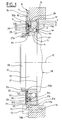
- bearing 1 includes a non-rotating outer ring 2 provided on its bore 2a of a toroidal raceway 3, an inner ring rotating 4 provided on its outer surface 4a with a path toroidal bearing 5, and a row of rolling elements 6, here balls, arranged between the raceway 3 of the outer ring 2 and the raceway 5 of the inner ring 4.
- the elements rollers 6 are maintained at regular circumferential spacings by a cage 7 made of synthetic material.
- the cage can be metallic. Of course, we could use marbles instead rollers or needles.
- the inner 4 and outer 2 rings massive, are obtained by conventional machining of a blank in steel, and have excellent rigidity. For reasons of axial compactness, the outer ring is shorter axially than the inner ring 4, but higher radially.
- the outer ring 2 is provided with two lateral surfaces radial 2b, 2c opposite and a cylindrical outer surface 2d.
- the outer ring 2 is devoid of joint fixing grooves.
- the inner ring 4 is also provided with a bore 4d and two radial lateral surfaces 4b, 4c opposite, the lateral surface 4c being in the same radial plane as the radial surface 2c and a bore 4d.
- the outer ring 2 is arranged in a casing 8 of form general ring, made of stamped sheet steel, and comprising a outer radial portion 9, a tubular portion 10 and a portion inner radial 11.
- the outer radial portion 9 is arranged at a end of the tubular portion 10 and extends outwards, while that the inner radial portion 11 is disposed at the opposite end of the tubular portion 10 and extends in the direction of the geometric axis 12 of the device.
- the outer surface 2d of the outer ring 2 is in contact with the tubular portion 10 and the radial surface 2c is in contact with the inner radial portion 11.
- the outer ring 2 is thus positioned relative to the housing 8 and axially immobilized in a meaning.
- Said inner radial portion 11 extends beyond the ring outer 2 towards the inner ring 4 with which it forms a narrow passage sealing the bearing on one side rolling elements 6.
- the radial portion interior 11 largely closes the radial annular space between the outer surface 4a of the inner ring 4 and the bore 2a of the outer ring 2.
- the housing 8 is fixed to a support such as a motor housing 13 electric, the outer surface of the tubular portion 10 of the housing 8 coming into the bore 13a of the casing 13, while the radial portion outer 9 is in contact with a radial end surface 13b of the housing 13.
- the attachment of the housing 8 to the housing 13 is provided by a plurality of screws of which a reference 14 is shown schematically in dotted lines in Figure 1 passing through a smooth through hole 15 of the outer radial portion 9 of the housing 8 and engaging in a threaded hole 16 formed in the housing 13 to from its radial surface 13b.
- the bearing 1 is mounted on the end 17 of a rotating shaft 18 of the electric motor.
- the end 17 of the shaft 18 comprises a cylindrical surface 19, bounded on the outside by a surface external cylindrical 20 threaded with a diameter smaller than that of the cylindrical surface 19.
- a shoulder is therefore formed between the surface cylindrical 19 and the outer surface cylindrical 20.
- the surface cylindrical 19 is limited on the opposite side by a shoulder 21.
- the inner ring 4 is fitted on the outer surface cylindrical 19 of the end 17 of the shaft 18.
- the lateral surface radial 4c of the inner ring 4 is in contact with the shoulder radial 21 of shaft 18.
- An annular spacer washer 22, of rectangular section, is arranged in contact with the radial surface 4b opposite the surface 4c and in contact with the outer cylindrical surface 19.
- the washer spacer 22 protrudes slightly axially beyond the surface cylindrical outer 19.
- a nut 23 is screwed onto the surface external thread 20 and presses axially on the washer spacer 22 on the side opposite to the inner ring 4.
- the inner ring 4 is tightened axially between the shoulder 21 and the washer 22, itself tightened by the nut 23. This thus ensures axial and circumferential attachment of the inner ring rotating 4 and shaft 18.
- the washer 22 has a diameter lower outer than inner ring 4 to increase the radial space available for an encoder 25.
- the washer 22 can be in one piece with the ring inner 4.
- the washer 22 can be fixed to the inner ring 4 before mounting the bearing, by example by gluing or welding.
- the bearing 1 further comprises a sensor assembly 24 with a rotary encoder 25 and a sensor block 26.
- the encoder 25 comprises a metal annular support 27 made of sheet metal a tubular portion of small diameter 27a is fitted onto the outer surface 4a of the inner ring 4 on the side of the shim 22 and a portion of large diameter 27b extends near the radial surface 2b of the outer ring 2.
- the encoder 25 also includes an active part 28 molded onto the large diameter portion 27b, on the side opposite to the outer ring 2 and radially at said outer ring 2, being substantially aligned with the surface radial 4b of the inner ring 4.
- the active part 28 is of the type magnetic multipole and can be made of plastoferrite or magnetized elastoferrite.
- the sensor unit 26 includes a sensor element 29, a card circuit board 30, a metal ring 31 and a flange 32.
- the metal ring 31 has an outer surface 31a in contact with the bore of the tubular portion 10 of the housing 2, a radial surface 31b in contact with the radial surface 2b of the ring outer 2, a bore 31c radially surrounding the end of large diameter of the encoder 25, a step 31d limiting the bore 31c, and another bore 31e beyond the step 31d to the outside.
- the other bore 31e has a diameter greater than that of bore 31c.
- the fixing of the ring 31 in the housing 8 is ensured by weld in the form of a bead 33 formed between the outer surface 31a of the ring 31 and the junction between the outer radial portion 9 and the tubular portion 10 of the housing 8.
- the outer ring 2 is held axially on one side by the inner radial portion 11 of the housing 8 and on the opposite side by the ring 31 rigidly fixed to the housing 8 by welding.
- the outer ring 2 will be fitted into the housing 8 preferably with a certain tightening and, when welding, a axial prestress can be exerted on the ring 31 in order to reinforce the rotationally joining the outer ring 2 and the housing 8.
- the metal ring 31 can be made of steel.
- the block sensor 26 thus cooperates with the housing 8 to immobilize axial of the bearing in one direction. Axial immobilization in the other direction is provided by the inner radial portion 11 of the housing 8.
- the outer ring 2 and the housing 8 being both made of steel have an almost identical coefficient of expansion, which eliminates the risks of accidental sliding in rotation of the outer ring 2 in the housing 8 during temperature increases (no differential expansions of parts in the contact area).
- the printed circuit board 30 has a radial shape annular, is mounted around bore 31st and comes into contact with the step 31 of the ring 30 extending radially inwards at from said step 31d at a short distance from the encoder 25.
- the element sensor 29 is supported by the printed circuit board 30 on the side of the encoder 25 while being disposed with a small axial air gap with respect to the active part 28 of said encoder 25.
- the flange 32 is in the form of a sheet metal disc of thin with short radial edges at both ends.
- the flange 32 is fitted by its outer radial edge 32a on the bore 31e of the ring 31 while maintaining the circuit board printed 30 in contact against the step 31d.
- the small axial rim diameter 32b of the flange 32 is directed towards the inner ring 4 while surrounding the spacer washer 22 at a short distance to form a narrow passage with said washer 22, thus ensuring sealing bearing and sensor.
- a signal transmission cable 34 can be connected to the printed circuit board 30 and encoder 29 for transmission of signals to the processing elements, not shown. Cable 34 can pass through a notch 36 formed in the ring 32 axially at bore 32e.
- the weld bead 33 can be produced by a laser beam and provides axial retention in one direction of the bearing and of the assembly sensor in the housing 8.
- the outer ring 2 can be rotatable and the ring interior 4 can be non-rotating.
Landscapes
- Engineering & Computer Science (AREA)
- General Engineering & Computer Science (AREA)
- Mechanical Engineering (AREA)
- Physics & Mathematics (AREA)
- General Physics & Mathematics (AREA)
- Power Engineering (AREA)
- Rolling Contact Bearings (AREA)
- Motor Or Generator Frames (AREA)
Abstract
Description
La présente invention concerne le domaine des paliers à roulement instrumentés munis d'un ensemble de détection des paramètres de rotation, tels que la position angulaire, le sens de rotation, la vitesse, l'accélération, etc. Ce type de roulement est souvent utilisé dans les moteurs électriques.The present invention relates to the field of bearings with instrumented bearing fitted with a detection assembly rotation parameters, such as angular position, direction of rotation, speed, acceleration, etc. This type of bearing is often used in electric motors.
Un moteur électrique comprend en général un rotor monté à rotation dans un stator grâce à deux roulements généralement de type rigide à billes et bagues en acier, disposés à chaque extrémité de l'arbre.An electric motor generally comprises a rotor mounted at rotation in a stator thanks to two bearings generally of the type rigid ball and steel rings, arranged at each end of the tree.
Les bagues intérieures des roulements sont montées sur l'arbre avec un ajustement serré, tandis que les bagues extérieures sont disposées dans des logements ménagés dans le carter du moteur. Le carter est généralement réalisé en un alliage léger, par exemple à base d'aluminium ou de magnésium.The inner rings of the bearings are mounted on the shaft with a tight fit, while the outer rings are arranged in housings in the motor housing. The housing is generally made of a light alloy, for example based aluminum or magnesium.
Dans les montages conventionnels, une bague extérieure de l'un des deux roulements est immobilisée axialement dans son logement par des moyens appropriés, tels que circlips et/ou épaulement et est éventuellement monté avec serrage dans le logement, tandis que la bague extérieure de l'autre roulement doit pouvoir se déplacer axialement légèrement par rapport au carter. Dans ce but, l'autre roulement est souvent monté libre dans son logement.In conventional assemblies, an outer ring of one of the two bearings is immobilized axially in its housing by suitable means, such as circlips and / or shoulder and is optionally mounted with clamping in the housing, while the outer ring of the other bearing must be able to move axially slightly relative to the housing. For this purpose, the other bearing is often mounted free in its housing.
En effet, lors de l'élévation de température du moteur, sous l'action des dilatations différentielles des différents constituants du moteur, la distance axiale séparant le deuxième roulement du premier roulement qui est axialement fixe par rapport au carter, est susceptible de varier légèrement. Le deuxième roulement doit donc être capable de se déplacer très légèrement dans le sens axial par rapport à son logement sans que le bon fonctionnement du montage n'en soit affecté.Indeed, when the engine temperature rises, under the action of differential expansions of the different constituents of the motor, the axial distance separating the second bearing from the first bearing which is axially fixed relative to the housing, is susceptible to vary slightly. The second bearing must therefore be capable of move very slightly in the axial direction with respect to its housing without affecting the proper functioning of the assembly.
Par ailleurs, dans certaines applications utilisant des moteurs électriques, par exemple dans un dispositif de commande de direction électrique de véhicule, les contraintes mécaniques et thermiques auxquelles est soumis le moteur sont importantes. L'arbre du moteur est soumis à des efforts axiaux relativement élevés et pouvant être dirigés dans des directions opposées, lesdits efforts devant être repris intégralement par le roulement fixé au carter axialement et sans prise de jeu axial par rapport au logement.In addition, in certain applications using motors electric, for example in a steering control device vehicle, mechanical and thermal constraints to which the engine is subjected are important. The motor shaft is subjected to relatively high axial forces and can be directed in opposite directions, said efforts to be resumed integrally by the bearing fixed to the housing axially and without socket axial play with respect to the housing.
D'autre part, les roulements du moteur qui sont généralement montés dans des logements en alliage léger à base d'aluminium ou de magnésium ne subissent pas les mêmes variations dimensionnelles que les logements. Il en résulte une prise de jeu radial de la bague non tournante par rapport à son logement et des risques de glissement en rotation de ladite bague non tournante par rapport audit logement.On the other hand, the motor bearings which are generally mounted in light alloy housings based on aluminum or magnesium do not undergo the same dimensional variations as housing. This results in a radial clearance of the ring not rotating relative to its housing and risks of slipping in rotation of said non-rotating ring relative to said housing.
Le document FR-A-2 824 367 décrit un ensemble comprenant un roulement instrumenté et un logement associé par une pièce d'emmanchement, en particulier pour un moteur de direction de véhicule. Toutefois, un tel roulement est inapte à supporter des charges axiales importantes sans prise de jeu ou détérioration du système en raison de la fragilité de l'anneau qui supporte le capteur, des languettes élastiques, et de la pièce d'emmanchement du roulement.Document FR-A-2 824 367 describes an assembly comprising an instrumented bearing and a housing associated by a part fitting, in particular for a steering motor of vehicle. However, such a bearing is incapable of supporting significant axial loads without backlash or deterioration of the system due to the fragility of the ring which supports the sensor, elastic tabs, and the fitting part of the rolling.
L'invention propose un dispositif de palier à roulement instrumenté apte à supporter des charges axiales importantes et de fortes variations de température.The invention provides a rolling bearing device instrumented able to withstand high axial loads and large temperature variations.
La présente invention se propose de remédier aux inconvénients évoqués ci-dessus.The present invention proposes to remedy the disadvantages mentioned above.
La présente invention propose un dispositif de palier à roulement instrumenté particulièrement économique et rigide.The present invention provides a bearing device for particularly economical and rigid instrumented bearing.
Le dispositif de roulement instrumenté, selon un aspect de l'invention, comprend un roulement pourvu d'une bague tournante et d'une bague non tournante, un bloc capteur monté solidaire de la bague non tournante, et un boítier logeant ledit roulement et ledit bloc capteur. Ledit boítier comprend deux portions radiales dirigées l'une vers l'axe du dispositif et l'autre vers l'extérieur, et une portion tubulaire raccordant lesdites portions radiales, le bloc capteur étant en contact avec un alésage de la portion tubulaire. La portion radiale dirigée vers l'extérieur forme un moyen de positionnement axial et de fixation du dispositif sur un support. La portion radiale dirigée vers l'axe du dispositif forme un moyen de positionnement axial et d'immobilisation axiale du roulement dans le boítier.The instrumented rolling device, according to one aspect of the invention comprises a bearing provided with a rotating ring and a non-rotating ring, a sensor block mounted integral with the non-rotating ring, and a housing housing said bearing and said block sensor. Said housing comprises two radial portions directed one towards the axis of the device and the other towards the outside, and a portion tubular connecting said radial portions, the sensor block being in contact with a bore in the tubular portion. The radial portion directed outwards forms a means of axial positioning and fixing the device on a support. The radial portion directed towards the axis of the device forms an axial positioning means and axial immobilization of the bearing in the housing.
Les portions radiales peuvent être disposées à des extrémités opposées de la portion tubulaire. Le boítier permet donc la fixation rigide du dispositif sur un support pour une large plage de température.The radial portions can be arranged at ends opposite of the tubular portion. The housing therefore allows fixing rigid device on a support for a wide range of temperature.
Avantageusement, la portion radiale dirigée vers l'axe du dispositif recouvre au moins partiellement une face latérale de la bague non tournante du roulement pour une immobilisation efficace et n'exerçant pas d'effort de torsion sur la bague extérieure.Advantageously, the radial portion directed towards the axis of the device at least partially covers a lateral face of the non-rotating ring of the bearing for efficient immobilization and not exerting a torsional force on the outer ring.
Avantageusement, la portion radiale dirigée vers l'axe du dispositif recouvre au moins partiellement l'espace radial entre les bagues du roulement. Ladite portion radiale peut former une étanchéité par passage étroit avec la bague tournante du roulement. On assure ainsi l'étanchéité d'un côté des éléments roulants de façon particulièrement économique. La présence d'un joint à lèvre frottante est possible mais pas indispensable. L'absence de joint permet également de se passer de rainures de fixation du joint dans l'une des bagues, d'où une économie supplémentaire. La bague extérieure présente donc une section transversale rectangulaire à l'exception du chemin de roulement. Par ailleurs, ladite portion radiale est en contact avec une face radiale de la bague non tournante, assurant ainsi son positionnement axial et son immobilisation axiale dans un sens.Advantageously, the radial portion directed towards the axis of the device at least partially covers the radial space between the bearing rings. Said radial portion can form a seal by narrow passage with the rotating ring of the bearing. We assure thus sealing one side of the rolling elements so particularly economical. The presence of a rubbing lip seal is possible but not essential. The absence of a joint allows also to do without seal fixing grooves in one of the rings, resulting in additional savings. The outer ring therefore has a rectangular cross section except for the Raceway. Furthermore, said radial portion is in contact with a radial face of the non-rotating ring, thus ensuring its axial positioning and its axial immobilization in one direction.
Dans un mode de réalisation de l'invention, l'immobilisation axiale du roulement et du bloc capteur dans le boítier est assurée dans un sens par la portion radiale dirigée vers l'axe du dispositif et dans l'autre sens par une soudure entre le boítier et le bloc capteur. La soudure peut être réalisée en cordon sur la périphérie du bloc capteur. La soudure peut comprendre un cordon continu. Alternativement, le cordon de soudure peut être discontinu.In one embodiment of the invention, the immobilizer axial of the bearing and the sensor block in the housing is ensured in a direction by the radial portion directed towards the axis of the device and in the other direction by a weld between the housing and the sensor block. The welding can be carried out in a bead on the periphery of the sensor block. The weld may include a continuous bead. Alternatively, the weld bead may be discontinuous.
Dans un autre mode de réalisation de l'invention, l'immobilisation axiale du roulement et du bloc capteur dans le boítier est assurée dans un sens par la portion radiale dirigée vers l'axe du dispositif et dans l'autre sens par une déformation du boítier. La déformation peut être obtenue par moletage. Une telle déformation dont l'obtention est économique, assure également un maintien mutuel extrêmement rigide de la bague non tournante du roulement et du boítier. La déformation du boítier peut être en contact avec la périphérie du bloc capteur. La déformation du boítier peut être continue ou discontinue. Le bloc capteur et la bague extérieure sont en contact par des surfaces radiales aptes à transmettre des efforts axiaux importants. Le bloc capteur et la bague extérieure sont donc fixés fermement au boítier.In another embodiment of the invention, the axial immobilization of the bearing and the sensor block in the housing is provided in one direction by the radial portion directed towards the axis of the device and in the other direction by a deformation of the housing. The deformation can be obtained by knurling. Such deformation which is economical to obtain, also ensures mutual maintenance extremely rigid non-rotating bearing ring and housing. The deformation of the housing can be in contact with the periphery of the sensor block. The deformation of the case can be continuous or discontinuous. The sensor block and the outer ring are in contact by radial surfaces capable of transmitting axial forces important. The sensor block and the outer ring are therefore fixed firmly to the case.
Dans un mode de réalisation de l'invention, le bloc capteur comprend une portion métallique périphérique en contact avec la bague non tournante du roulement.In one embodiment of the invention, the sensor block includes a peripheral metal portion in contact with the non-rotating bearing ring.
Avantageusement, le bloc capteur comprend un flasque de protection et de fermeture fixé rigidement sur une partie périphérique dudit bloc capteur. Le flasque peut se présenter sous la forme d'un disque pourvu de rebords tubulaires et assure l'étanchéité par passage étroit de la zone voisine du capteur. On peut, là encore, éviter l'utilisation d'un joint à lèvre nécessitant une surface de frottement rectifiée, et une gorge de support.Advantageously, the sensor block comprises a flange of protection and closure rigidly fixed on a peripheral part of said sensor block. The flange can be in the form of a disc provided with tubular flanges and ensures sealing by passage close to the area near the sensor. Here again, we can avoid the use of a lip seal requiring a friction surface ground, and a support groove.
Avantageusement, le bloc capteur comprend une carte de circuit imprimé supportant au moins un élément capteur et maintenue en place par un flasque.Advantageously, the sensor block includes a card printed circuit supporting at least one sensor element and maintained in place by a flange.
Avantageusement, le bloc capteur comprend un anneau formant une cale axiale entre la bague non tournante et le moyen de fixation formé par la déformation ou le cordon de soudure du boítier. En d'autres termes, le roulement est immobilisé axialement dans sens par la portion radiale intérieure du boítier, dans l'autre sens par la coopération du bloc capteur et du moyen de fixation faisant partie du boítier.Advantageously, the sensor block comprises a ring forming an axial shim between the non-rotating ring and the fixing means formed by the deformation or the weld bead of the housing. In in other words, the bearing is immobilized axially in direction by the inner radial portion of the housing, in the other direction by the cooperation of the sensor unit and the fixing means forming part of the housing.
L'invention propose également un moteur électrique comprenant un carter, un stator, un rotor et un dispositif de roulement instrumenté comprenant un roulement pourvu d'un bague tournante solidaire du rotor, une bague non tournante solidaire du carter, un bloc capteur monté solidaire de la bague non tournante, et un boítier logeant ledit roulement et ledit bloc capteur. Le boítier comprend deux portions radiales dirigées l'une vers l'axe du dispositif et l'autre vers l'extérieur, et une portion tubulaire raccordant lesdites portions radiales. La portion radiale dirigée vers l'extérieur forme un moyen de positionnement axial et de fixation du dispositif sur le carter. La portion radiale dirigée vers l'axe du dispositif forme un moyen de positionnement axial et d'immobilisation axiale du roulement dans le boítier. Un tel moteur électrique peut être construit de façon économique tout en étant apte à supporter les charges axiales importantes et de fortes variations de température.The invention also provides an electric motor comprising a housing, a stator, a rotor and a rolling device instrumented comprising a bearing provided with a rotating ring secured to the rotor, a non-rotating ring secured to the housing, a block sensor mounted integral with the non-rotating ring, and a housing housing said bearing and said sensor block. The case includes two radial portions directed one towards the axis of the device and the other towards the outside, and a tubular portion connecting said portions radials. The radial portion directed towards the outside forms a means of axial positioning and fixing of the device on the casing. The radial portion directed towards the axis of the device forms a means of axial positioning and axial immobilization of the bearing in the housing. Such an electric motor can be constructed so economical while being able to withstand axial loads large and large temperature variations.
Avantageusement, la portion radiale dirigée vers l'extérieur est fixée sur le carter, par exemple par vissage. On supprime ainsi le jeu axial entre le boítier le carter. La portion radiale dirigée vers l'extérieur peut être en contact avec une surface radiale du carter en vue d'une bonne transmission des efforts axiaux. Le jeu axial entre la bague non tournante et le boítier est supprimé par la solidarisation axiale obtenue par soudure ou par déformation du boítier.Advantageously, the radial portion directed towards the outside is fixed to the housing, for example by screwing. This removes the game axial between the housing and the housing. The radial portion directed towards the exterior may be in contact with a radial surface of the housing in view of a good transmission of axial forces. The axial clearance between the non-rotating ring and the case is removed by the connection axial obtained by welding or by deformation of the housing.
Un anneau codeur peut être prévu, supporté par la bague tournante du roulement tout en présentant un faible entrefer avec le capteur. L'anneau codeur peut être de type magnétique multipolaire. L'absence de jeu axial entre le roulement et l'anneau codeur garantit un entrefer constant et donc un signal de sortie du capteur fiable. En outre, le dispositif de roulement forme une unité compacte facile à mettre en place dans un logement de carter. Il est possible d'élargir les tolérances de fabrication du logement du carter, la bague non tournante du roulement n'étant pas emmanchée directement dans le carter mais par l'intermédiaire du boítier en tôle.An encoder ring can be provided, supported by the ring rotating bearing while having a small air gap with the sensor. The encoder ring can be of the multipolar magnetic type. The absence of axial play between the bearing and the encoder ring guarantees a constant air gap and therefore a reliable sensor output signal. In in addition, the rolling device forms a compact unit easy to install in a housing. It is possible to expand the manufacturing tolerances of the housing of the housing, the ring not bearing rotation not being fitted directly into the casing but through the sheet metal housing.
La présente invention sera mieux comprise à l'étude de la description détaillée de quelques modes de réalisation pris à titre nullement limitatifs et illustrés par les dessins annexés, sur lesquels:
- la figure 1 est une vue en coupe axiale d'une extrémité d'un moteur électrique équipé d'un dispositif de roulement selon un aspect de l'invention;
- la figure 2 est une vue de détail de la figure 1; et
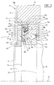
- la figure 3 est une variante de la figure 2.
- Figure 1 is an axial sectional view of one end of an electric motor equipped with a rolling device according to one aspect of the invention;
- Figure 2 is a detail view of Figure 1; and
- FIG. 3 is a variant of FIG. 2.
Comme on peut le voir sur les figures 1 et 2, le roulement 1
comprend une bague extérieure non tournante 2 pourvue sur son
alésage 2a d'un chemin de roulement toroïdal 3, une bague intérieure
tournante 4 pourvue sur sa surface extérieure 4a d'un chemin de
roulement toroïdal 5, et une rangée d'éléments roulants 6, ici des
billes, disposés entre le chemin de roulement 3 de la bague extérieure
2 et le chemin de roulement 5 de la bague intérieure 4. Les éléments
roulants 6 sont maintenus à espacements circonférentiels réguliers par
une cage 7 réalisée en matériau synthétique. En variante, la cage peut
être métallique. Bien entendu, on pourrait utiliser à la place des billes
des rouleaux ou des aiguilles. Les bagues intérieure 4 et extérieure 2,
massives, sont obtenues par usinage conventionnel d'une ébauche en
acier, et présentent une excellente rigidité. Pour des raisons de
compacité axiale, la bague extérieure est moins longue axialement que
la bague intérieure 4, mais plus haute radialement.As can be seen in Figures 1 and 2, bearing 1
includes a non-rotating
La bague extérieure 2 est pourvue de deux surfaces latérales
radiales 2b, 2c opposées et d'une surface extérieure cylindrique 2d.
Dans la variante représentée, la bague extérieure 2 est dépourvue de
rainures de fixation de joints. La bague intérieure 4 est également
pourvue d'un alésage 4d et de deux surfaces latérales radiales 4b, 4c
opposées, la surface latérale 4c étant dans le même plan radial que la
surface radiale 2c et d'un alésage 4d.The
La bague extérieure 2 est disposée dans un boítier 8 de forme
générale annulaire, réalisé en tôle d'acier emboutie, et comprenant une
portion radiale extérieure 9, une portion tubulaire 10 et une portion
radiale intérieure 11. La portion radiale extérieure 9 est disposée à une
extrémité de la portion tubulaire 10 et s'étend vers l'extérieur, tandis
que la portion radiale intérieure 11 est disposée à l'extrémité opposée
de la portion tubulaire 10 et s'étend en direction de l'axe géométrique
12 du dispositif.The
La surface extérieure 2d de la bague extérieure 2 est en contact
avec la portion tubulaire 10 et la surface radiale 2c est en contact avec
la portion radiale intérieure 11. La bague extérieure 2 est ainsi
positionnée par rapport au boítier 8 et immobilisée axialement dans un
sens. Ladite portion radiale intérieure 11 s'étend au-delà de la bague
extérieure 2 en direction de la bague intérieure 4 avec laquelle elle
forme un passage étroit assurant l'étanchéité du roulement d'un côté
des éléments roulants 6. En d'autres termes, la portion radiale
intérieure 11 obture en majeure partie l'espace annulaire radial entre
la surface extérieure 4a de la bague intérieure 4 et l'alésage 2a de la
bague extérieure 2.The
Le boítier 8 est fixé à un support tel qu'un carter 13 de moteur
électrique, la surface extérieure de la portion tubulaire 10 du boítier 8
venant dans l'alésage 13a du carter 13, tandis que la portion radiale
extérieure 9 est en contact avec une surface radiale d'extrémité 13b du
carter 13. La fixation du boítier 8 sur le carter 13 est assurée par une
pluralité de vis dont une référencée 14 est représentée
schématiquement en traits pointillés sur la figure 1 passant dans un
trou traversant lisse 15 de la portion radiale extérieure 9 du boítier 8
et venant en prise dans un trou fileté 16 ménagé dans le boítier 13 à
partir de sa surface radiale 13b.The
Le roulement 1 est monté sur l'extrémité 17 d'un arbre tournant
18 du moteur électrique. L'extrémité 17 de l'arbre 18 comprend une
surface cylindrique 19, limitée du côté extérieur par une surface
extérieure cylindrique 20 filetée de diamètre inférieur à celui de la
surface cylindrique 19. Un épaulement est donc formé entre la surface
cylindrique 19 et la surface extérieure cylindrique 20. La surface
cylindrique 19 est limitée du côté opposé par un épaulement 21.The
La bague intérieure 4 est emmanchée sur la surface extérieure
cylindrique 19 de l'extrémité 17 de l'arbre 18. La surface latérale
radiale 4c de la bague intérieure 4 est en contact avec l'épaulement
radial 21 de l'arbre 18. The
Une rondelle entretoise annulaire 22, de section rectangulaire,
est disposée en contact avec la surface radiale 4b opposée à la surface
4c et en contact avec la surface cylindrique extérieure 19. La rondelle
entretoise 22 fait légèrement saillie axialement au-delà de la surface
extérieure cylindrique 19. Un écrou 23 est vissé sur la surface
extérieure filetée 20 et vient appuyer axialement sur la rondelle
entretoise 22 du côté opposé à la bague intérieure 4. En d'autres
termes, la bague intérieure 4 est serrée axialement entre l'épaulement
21 et la rondelle 22, elle-même serrée par l'écrou 23. On assure ainsi
la solidarisation axiale et circonférentielle de la bague intérieure
tournante 4 et de l'arbre 18. La rondelle 22 présente un diamètre
extérieur inférieur à celui de la bague intérieure 4 pour augmenter
l'espace radial disponible pour un codeur 25.An
En variante, la rondelle 22 peut être monobloc avec la bague
intérieure 4. Dans une autre variante, la rondelle 22 peut être fixée à la
bague intérieure 4 préalablement au montage du roulement, par
exemple par collage ou soudage.As a variant, the
Le roulement 1 comprend en outre un ensemble capteur
d'informations 24 équipé d'un codeur tournant 25 et d'un bloc capteur
26. Le codeur 25 comprend un support annulaire métallique 27 en tôle
dont une portion tubulaire de faible diamètre 27a est emmanchée sur la
surface extérieure 4a de la bague intérieure 4 du côté de la cale 22 et
dont une portion de grand diamètre 27b s'étend à proximité de la
surface radiale 2b de la bague extérieure 2.The
On rappellera ici que la bague intérieure 4 est plus large
axialement que la bague extérieure 2, ce qui permet, d'une part, de
supporter le codeur 25 par emmanchement et, d'autre part, de faire
voisiner la portion de grand diamètre 27b du support 27 et la surface
radiale 2b de la bague extérieure 2. Le codeur 25 comprend également
une partie active 28 surmoulée sur la portion de grand diamètre 27b,
du côté opposé à la bague extérieure 2 et radialement au niveau de
ladite bague extérieure 2, en étant sensiblement alignée avec la surface
radiale 4b de la bague intérieure 4. La partie active 28 est de type
magnétique multipolaire et peut être réalisée en plastoferrite ou en
élastoferrite magnétisée.It will be recalled here that the
Le bloc capteur 26 comprend un élément capteur 29, une carte
de circuit imprimé 30, un anneau métallique 31 et un flasque 32.The
L'anneau métallique 31 présente une surface extérieure 31a en
contact avec l'alésage de la portion tubulaire 10 du boítier 2, une
surface radiale 31b en contact avec la surface radiale 2b de la bague
extérieure 2, un alésage 31c entourant radialement l'extrémité de
grand diamètre du codeur 25, un redan 31d limitant l'alésage 31c, et
un autre alésage 31e au-delà du redan 31d vers l'extérieur. L'autre
alésage 31e présente un diamètre supérieur à celui de l'alésage 31c.The
La fixation de l'anneau 31 dans le boítier 8 est assurée par
soudure sous la forme d'un cordon 33 formé entre la surface extérieure
31a de l'anneau 31 et la jonction entre la portion radiale extérieure 9
et la portion tubulaire 10 du boítier 8. Ainsi, la bague extérieure 2 est
maintenue axialement d'un côté par la portion radiale intérieure 11 du
boítier 8 et du côté opposé par l'anneau 31 fixé rigidement au boítier 8
par soudure. La bague extérieure 2 sera emmanchée dans le boítier 8
de préférence avec un certain serrage et, lors de la soudure, une
précontrainte axiale pourra être exercée sur l'anneau 31 afin de
renforcer la solidarisation en rotation de la bague extérieure 2 et du
boítier 8. L'anneau métallique 31 peut être réalisé en acier. Le bloc
capteur 26 coopère ainsi avec le boítier 8 pour assurer l'immobilisation
axiale du roulement dans un sens. L'immobilisation axiale dans l'autre
sens est assurée par la portion radiale intérieure 11 du boítier 8.The fixing of the
La bague extérieure 2 et le boítier 8 étant réalisés tous deux en
acier ont un coefficient de dilatation quasi identique, ce qui élimine
les risques de glissement accidentel en rotation de la bague extérieure
2 dans le boítier 8 lors des élévations de température (pas de
dilatations différentielles des pièces dans la zone de contact).The
La carte de circuit imprimé 30 présente une forme radiale
annulaire, est montée autour de l'alésage 31e et vient en contact avec
le redan 31 de l'anneau 30 en s'étendant radialement vers l'intérieur à
partir dudit redan 31d à faible distance du codeur 25. L'élément
capteur 29 est supporté par la carte de circuit imprimé 30 du côté du
codeur 25 en étant disposé avec un faible entrefer axial par rapport à
la partie active 28 dudit codeur 25.The printed
Le flasque 32 se présente sous la forme d'un disque en tôle de
faible épaisseur pourvu de courts rebords radiaux à ses deux
extrémités. Le flasque 32 est emmanché par son rebord radial extérieur
32a sur l'alésage 31e de l'anneau 31 en maintenant la carte de circuit
imprimé 30 en contact contre le redan 31d. Le rebord axial de petit
diamètre 32b du flasque 32 est dirigé vers la bague intérieure 4 tout en
entourant la rondelle entretoise 22 à faible distance pour former un
passage étroit avec ladite rondelle 22, garantissant ainsi l'étanchéité
du roulement et du capteur.The
Le défilement à rotation de la partie active 28 du codeur 25 en
regard du capteur 29 magnétosensible, par exemple une cellule à effet
Hall, permet de détecter les paramètres de rotation recherchés, tels que
la vitesse et le déplacement angulaire de l'arbre sur lequel est montée
la bague tournante du roulement.The scrolling scrolling of the
Un câble de transmission de signaux 34 peut être relié à la
carte de circuit imprimé 30 et au codeur 29 pour la transmission de
signaux vers les éléments de traitement, non représentés. Le câble 34
peut passer par une encoche 36 ménagée dans l'anneau 32 axialement
au niveau de l'alésage 32e.A
Le cordon de soudure 33 peut être réalisé par un faisceau laser
et assure la retenue axiale dans un sens du roulement et de l'ensemble
capteur dans le boítier 8.The
Dans le mode de réalisation illustré sur la figure 3, les
éléments semblables portent les mêmes références. Ce mode de
réalisation se distingue du précédent par le fait que le cordon de
soudure est remplacé par une déformation radiale 35 de la portion
tubulaire 10 du boítier 8 pour former une saillie dirigée vers
l'intérieur, assurant la retenue de l'anneau 31 du bloc capteur 26 et la
retenue de la bague extérieure 2 du roulement. La déformation radiale
35 peut être réalisée facilement au moyen d'une molette. In the embodiment illustrated in FIG. 3, the
similar elements have the same references. This mode of
achievement is distinguished from the previous one by the fact that the cord of
weld is replaced by a
On réalise ainsi, grâce à l'invention, un dispositif permettant la fixation d'un roulement instrumenté sur un élément fixe et présentant de nombreux avantages. Le dispositif est extrêmement rigide et compact et permet de supporter, sans jeu axial entre le roulement et l'élément fixe, une charge axiale importante dans les deux sens. L'ensemble constitué par le roulement instrumenté et le boítier est facile à réaliser et à mettre en place. Enfin, le dispositif suivant l'invention permet de réduire considérablement les risques de rotation accidentelle de la bague fixe lors d'une élévation en température.This makes it possible, thanks to the invention, a device allowing the attachment of an instrumented bearing to a fixed element having many advantages. The device is extremely rigid and compact and supports, without axial play between the bearing and the fixed element, a significant axial load in both directions. The assembly consisting of the instrumented bearing and the housing is easy to make and set up. Finally, the following device the invention considerably reduces the risks of rotation accidental fixed ring during a rise in temperature.
En variante, la bague extérieure 2 peut être tournante et la bague
intérieure 4 peut être non tournante.Alternatively, the
Claims (13)
Applications Claiming Priority (2)
| Application Number | Priority Date | Filing Date | Title |
|---|---|---|---|
| FR0305421 | 2003-05-02 | ||
| FR0305421A FR2854443B1 (en) | 2003-05-02 | 2003-05-02 | INSTRUMENT BEARING DEVICE |
Publications (1)
| Publication Number | Publication Date |
|---|---|
| EP1473570A1 true EP1473570A1 (en) | 2004-11-03 |
Family
ID=32982357
Family Applications (1)
| Application Number | Title | Priority Date | Filing Date |
|---|---|---|---|
| EP04291087A Withdrawn EP1473570A1 (en) | 2003-05-02 | 2004-04-27 | Rolling bearing with integrated speed sensing device |
Country Status (2)
| Country | Link |
|---|---|
| EP (1) | EP1473570A1 (en) |
| FR (1) | FR2854443B1 (en) |
Cited By (1)
| Publication number | Priority date | Publication date | Assignee | Title |
|---|---|---|---|---|
| WO2016192752A1 (en) * | 2015-05-29 | 2016-12-08 | Aktiebolaget Skf | Rolling bearing assembly with pre-stressing element and sensor unit |
Citations (5)
| Publication number | Priority date | Publication date | Assignee | Title |
|---|---|---|---|---|
| US5942890A (en) * | 1997-07-23 | 1999-08-24 | Precision, Inc. | Rotating shaft monitoring device with a universal attaching mechanism |
| US6352370B1 (en) * | 1999-04-14 | 2002-03-05 | The Torrington Company | Bearing with built-in encoder |
| FR2824367A1 (en) * | 2001-05-04 | 2002-11-08 | Roulements Soc Nouvelle | ASSEMBLY COMPRISING AN INSTRUMENT BEARING AND A HOUSING ASSOCIATED BY A SLEEVE PIECE |
| FR2826413A1 (en) * | 2001-06-20 | 2002-12-27 | Skf Ab | INSTRUMENT BEARING |
| DE20302129U1 (en) * | 2002-02-18 | 2003-04-24 | Papst-Motoren GmbH & Co. KG, 78112 St. Georgen | Electronically commutated internal rotor motor |
Family Cites Families (1)
| Publication number | Priority date | Publication date | Assignee | Title |
|---|---|---|---|---|
| FR2835542B1 (en) * | 2002-02-06 | 2004-07-02 | Skf Ab | DRUM MACHINE HAVING A DRUM ROTATION PARAMETER SENSOR ASSEMBLY |
-
2003
- 2003-05-02 FR FR0305421A patent/FR2854443B1/en not_active Expired - Fee Related
-
2004
- 2004-04-27 EP EP04291087A patent/EP1473570A1/en not_active Withdrawn
Patent Citations (5)
| Publication number | Priority date | Publication date | Assignee | Title |
|---|---|---|---|---|
| US5942890A (en) * | 1997-07-23 | 1999-08-24 | Precision, Inc. | Rotating shaft monitoring device with a universal attaching mechanism |
| US6352370B1 (en) * | 1999-04-14 | 2002-03-05 | The Torrington Company | Bearing with built-in encoder |
| FR2824367A1 (en) * | 2001-05-04 | 2002-11-08 | Roulements Soc Nouvelle | ASSEMBLY COMPRISING AN INSTRUMENT BEARING AND A HOUSING ASSOCIATED BY A SLEEVE PIECE |
| FR2826413A1 (en) * | 2001-06-20 | 2002-12-27 | Skf Ab | INSTRUMENT BEARING |
| DE20302129U1 (en) * | 2002-02-18 | 2003-04-24 | Papst-Motoren GmbH & Co. KG, 78112 St. Georgen | Electronically commutated internal rotor motor |
Cited By (1)
| Publication number | Priority date | Publication date | Assignee | Title |
|---|---|---|---|---|
| WO2016192752A1 (en) * | 2015-05-29 | 2016-12-08 | Aktiebolaget Skf | Rolling bearing assembly with pre-stressing element and sensor unit |
Also Published As
| Publication number | Publication date |
|---|---|
| FR2854443B1 (en) | 2006-05-26 |
| FR2854443A1 (en) | 2004-11-05 |
Similar Documents
| Publication | Publication Date | Title |
|---|---|---|
| EP1452753B1 (en) | Roller bearing with integrated sensor | |
| EP1037051B1 (en) | Instrumented roller bearing | |
| EP0821240A1 (en) | Roller bearing with measuring sensor | |
| EP0875683B1 (en) | Rolling contact bearing with an information sensor | |
| FR2813644A1 (en) | BEARING DEVICE WITH INSTRUMENT BEARING, IN PARTICULAR FOR CONTROL WHEEL | |
| WO2000067038A1 (en) | Roller bearing with information sensor | |
| EP1366370B1 (en) | Roller device with instrumented ball bearing | |
| FR2991412A1 (en) | BEARING BEARING DEVICE FOR STEERING COLUMN. | |
| FR2762056A1 (en) | ROLLING BEARING WITH INFORMATION SENSOR | |
| EP1088236B1 (en) | Ball bearing with incorporated encoder | |
| EP1397690B1 (en) | Roller bearing equipped with an angular velocity sensor | |
| FR2993332A1 (en) | CAGE FOR BEARING BEARING, BEARING BEARING AND ELECTRIC DIRECTION OF MOTOR VEHICLE | |
| FR2835580A1 (en) | Ball bearing for electric motor etc. with outer race fitting within cylindrical seat | |
| EP1252524B1 (en) | Instrumented antifriction bearing device with temporary angular pre-indexing of the encoder relative to the sensor | |
| EP1266228A1 (en) | Instrumented antifriction bearing provided with a sealing device | |
| EP1433968B1 (en) | Compact locked antifriction roller bearing | |
| EP1693677A1 (en) | Device for detecting the rotation parameters of two elements | |
| FR2823811A1 (en) | Wheel hub for motorcycles has stress bearing ABS sensor | |
| FR2792427A1 (en) | Neutral point setting device for steering wheel with no axis comprises circular plate attached to two springs setting rotation of plate or of rotating ring | |
| EP1473570A1 (en) | Rolling bearing with integrated speed sensing device | |
| EP1619478A2 (en) | Detector of a wheel rotation parameter, particularly a vehicle wheel | |
| FR3119427A1 (en) | Plain or rolling bearing fitted with a sealing device with a seal seat close to the axis of revolution | |
| FR2886693A1 (en) | ANTI-ROTATION DEVICE FOR ROLLING BEARING, AND BEARING AND MACHINE THEREFOR | |
| EP1359423B1 (en) | Roller assembly having a roller bearing being equipped with an angular speed sensor | |
| EP1245959A1 (en) | Roller bearing assembly equipped with a sensor |
Legal Events
| Date | Code | Title | Description |
|---|---|---|---|
| PUAI | Public reference made under article 153(3) epc to a published international application that has entered the european phase |
Free format text: ORIGINAL CODE: 0009012 |
|
| AK | Designated contracting states |
Kind code of ref document: A1 Designated state(s): AT BE BG CH CY CZ DE DK EE ES FI FR GB GR HU IE IT LI LU MC NL PL PT RO SE SI SK TR |
|
| AX | Request for extension of the european patent |
Extension state: AL HR LT LV MK |
|
| RIN1 | Information on inventor provided before grant (corrected) |
Inventor name: HUHN, ELKE Inventor name: HUHN, NORBERT Inventor name: NIARFEIX, FRANEOIS |
|
| 17P | Request for examination filed |
Effective date: 20050309 |
|
| AKX | Designation fees paid |
Designated state(s): AT BE BG CH CY CZ DE DK EE ES FI FR GB GR HU IE IT LI LU MC NL PL PT RO SE SI SK TR |
|
| STAA | Information on the status of an ep patent application or granted ep patent |
Free format text: STATUS: THE APPLICATION IS DEEMED TO BE WITHDRAWN |
|
| 18D | Application deemed to be withdrawn |
Effective date: 20091102 |