EP1473559A2 - Method of simulating rolling tire - Google Patents
Method of simulating rolling tire Download PDFInfo
- Publication number
- EP1473559A2 EP1473559A2 EP04009551A EP04009551A EP1473559A2 EP 1473559 A2 EP1473559 A2 EP 1473559A2 EP 04009551 A EP04009551 A EP 04009551A EP 04009551 A EP04009551 A EP 04009551A EP 1473559 A2 EP1473559 A2 EP 1473559A2
- Authority
- EP
- European Patent Office
- Prior art keywords
- tire
- model
- speed
- tire model
- road
- Prior art date
- Legal status (The legal status is an assumption and is not a legal conclusion. Google has not performed a legal analysis and makes no representation as to the accuracy of the status listed.)
- Granted
Links
Images


Classifications
-
- B—PERFORMING OPERATIONS; TRANSPORTING
- B60—VEHICLES IN GENERAL
- B60C—VEHICLE TYRES; TYRE INFLATION; TYRE CHANGING; CONNECTING VALVES TO INFLATABLE ELASTIC BODIES IN GENERAL; DEVICES OR ARRANGEMENTS RELATED TO TYRES
- B60C11/00—Tyre tread bands; Tread patterns; Anti-skid inserts
- B60C11/03—Tread patterns
- B60C11/0318—Tread patterns irregular patterns with particular pitch sequence
-
- B—PERFORMING OPERATIONS; TRANSPORTING
- B60—VEHICLES IN GENERAL
- B60C—VEHICLE TYRES; TYRE INFLATION; TYRE CHANGING; CONNECTING VALVES TO INFLATABLE ELASTIC BODIES IN GENERAL; DEVICES OR ARRANGEMENTS RELATED TO TYRES
- B60C19/00—Tyre parts or constructions not otherwise provided for
-
- B—PERFORMING OPERATIONS; TRANSPORTING
- B60—VEHICLES IN GENERAL
- B60C—VEHICLE TYRES; TYRE INFLATION; TYRE CHANGING; CONNECTING VALVES TO INFLATABLE ELASTIC BODIES IN GENERAL; DEVICES OR ARRANGEMENTS RELATED TO TYRES
- B60C99/00—Subject matter not provided for in other groups of this subclass
- B60C99/006—Computer aided tyre design or simulation
-
- G—PHYSICS
- G01—MEASURING; TESTING
- G01M—TESTING STATIC OR DYNAMIC BALANCE OF MACHINES OR STRUCTURES; TESTING OF STRUCTURES OR APPARATUS, NOT OTHERWISE PROVIDED FOR
- G01M17/00—Testing of vehicles
- G01M17/007—Wheeled or endless-tracked vehicles
- G01M17/02—Tyres
-
- G—PHYSICS
- G06—COMPUTING OR CALCULATING; COUNTING
- G06F—ELECTRIC DIGITAL DATA PROCESSING
- G06F30/00—Computer-aided design [CAD]
- G06F30/10—Geometric CAD
- G06F30/15—Vehicle, aircraft or watercraft design
-
- G—PHYSICS
- G06—COMPUTING OR CALCULATING; COUNTING
- G06F—ELECTRIC DIGITAL DATA PROCESSING
- G06F30/00—Computer-aided design [CAD]
- G06F30/20—Design optimisation, verification or simulation
- G06F30/23—Design optimisation, verification or simulation using finite element methods [FEM] or finite difference methods [FDM]
-
- Y—GENERAL TAGGING OF NEW TECHNOLOGICAL DEVELOPMENTS; GENERAL TAGGING OF CROSS-SECTIONAL TECHNOLOGIES SPANNING OVER SEVERAL SECTIONS OF THE IPC; TECHNICAL SUBJECTS COVERED BY FORMER USPC CROSS-REFERENCE ART COLLECTIONS [XRACs] AND DIGESTS
- Y02—TECHNOLOGIES OR APPLICATIONS FOR MITIGATION OR ADAPTATION AGAINST CLIMATE CHANGE
- Y02T—CLIMATE CHANGE MITIGATION TECHNOLOGIES RELATED TO TRANSPORTATION
- Y02T90/00—Enabling technologies or technologies with a potential or indirect contribution to GHG emissions mitigation
Definitions
- the present invention relates to a method of simulating rolling tire which is capable of analyzing vibration characteristics during rolling on a road with high accuracy.
- a computer simulation is used for development of a tire.
- the computer simulation enables performance to some extent to be predicted without experimentally manufacturing the tire.
- a rolling simulation in which a tire model is made to roll on a road model.
- Each model is consisting of the finite elements.
- the vibration characteristic of the tire can be predicted by obtaining a time history of vertical force inputted into a tire axis of the rolling tire model.
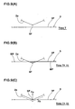
- FIG. 14 is a side view partly showing a visualized tire model.
- Small three-dimensional elements e ... are sequentially arranged in a tire circumferential direction at a tread surface a of the tire model.
- Each of the three-dimensional elements e ... consists of a tetrahedral or hexahedral solid element or the like.
- the surface of each of the elements is flat. Therefore, the tread surface "a" of the tire model and a belt model, not shown, defined inside thereof are not formed into a perfect circle but a regular polygonal shape, as viewed from the side.
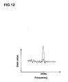
- FIG. 11B is a graph showing results of a simulation, in which the above-described tire model is made to roll on a road model at a constant running speed.
- This graph shows the results of a frequency-analysis of the time history of the vertical force inputted into the tire axis of the tire model, wherein the horizontal axis designates a frequency while a vertical axis designates gain value thereof.
- the simulation results include a peak vibration component NP, which should not have been generated in an actual tire.
- the peak vibration component NP is considered to be generated by summing forces for periodically lifting up vertexes "et" of the polygonal shape defined by the tread surface "a" of the tire model from the surface of the road every time the vertex collides with a road model.
- reference character "N” is the number of elements, which have a great rigidity and are arranged in the tire circumferential direction, of the tire model exemplified by an element made of tread rubber or an element consisting of a belt layer; and reference character “R” is a rotating speed per second of the tire model determined by a running speed V and an outer diameter of the tire model.
- the tire model can be more formed into a perfect circle by increasing the number "N" of elements of the tire circumferential direction.
- such a method only transfers the frequency Ft to a high frequency region.
- the increase in the number "N" of elements markedly prolongs a calculation time of the simulation.
- a principal object of the present invention is to provide a method of simulating rolling tire capable of reducing a peak vibration component (noise) dependent on the number of elements of a tire model from an analysis result.
- a method of simulating rolling tire according to the present invention comprises the steps of: modeling the tire in finite elements to make a tire model; modeling the surface of the road in finite elements to make a road model; executing a simulation in which the tire model is made to roll on the road model at a predetermined speed; and obtaining information about the tire model; the speed of the tire model being varied by repeating an increase and a decrease based on a predetermined reference speed.
- the speed of the tire model should be varied as a function of a time in a sin wave or zigzag manner. Moreover, it is desirable that the speed of the tire model should be increased or decreased within ⁇ 20% of the reference speed. It is further desirable that the information includes at least a vertical force inputted into the tire axis of the tire model. Additionally, it is desirable that the above-described tire simulation method should further comprise the steps of: frequency-analyzing a waveform as a time history of the vertical force; and calculating at least one of a gain level, a peak frequency and a gain value of a waveform obtained by the frequency-analysis.
- FIG. 1 shows a computer apparatus 1 for carrying out a simulation method according to the present invention.
- the computer apparatus 1 includes a main unit 1a, a keyboard 1b and a mouse 1c serving as input means, and a display 1d serving as output means.
- the main unit 1a is appropriately provided with a central processing unit (abbreviated as "a CPU"), a ROM, a working memory, a large-capacity storage device such as a magnetic disk, and drives 1a1 and 1a2 for a CD-ROM or a flexible disk.
- the large-capacity storage device stores therein processing procedures (i.e., programs) for executing a method, described later.
- An Engineering Work Station and the like are preferably used as the computer apparatus 1.
- FIG. 2 illustrates one example of processing procedures in the present preferred embodiment.
- a tire model 2 is first modeled (step S1).
- FIG. 3 shows one example of the tire model 2 visually in a three-dimensional fashion.
- FIG. 4 schematically shows a part of a cross section of the tire model 2 cut along a tire equator.
- the tire model 2 is modeled by dividing a tire to be analyzed (irrespective of the actual presence) into the finite elements 2a, 2b, 2c ... .
- Each of the elements can be defined in such a manner as to be numerically analyzed.
- the numeric analysis signifies to freely carry out modification calculation by at least one numerically analyzing method.
- the numerically analyzing methods include, for example, an infinite element method, an infinite volume method, calculus of finite differences and a boundary element method.
- a coordinate value of a point in a X-Y-Z coordinate system the shape of the element, the properties of a material (e.g., a density, a modulus of elasticity, a loss tangent and a damping coefficient) and the like are defined with respect to each of the elements 2a, 2b, 2c ... . Consequently, the substance of the tire model 2 is expressed by numerical data which can be operated in the computer apparatus 1.
- a two-dimensional element or a three-dimensional element is used as each of the elements 2a, 2b, 2c ... .
- the two-dimensional elements include, for example, a triangular membrane element and a quadrilateral membrane element.
- the three-dimensional elements include, for example, tetrahedral to hexahedral solid elements.
- the tire model 2 in the present preferred embodiment is comprises a tire body 2A constituting the inside structure of the tire; and a tread rubber 2B disposed outside of the tire body 2A.
- the tire body 2A includes a belt model 6 shown in FIG. 5B which models a belt layer 5 shown in FIG. 5A, and a body unit 7 which models a portion (such as a carcass, a side wall or a bead) located in a tire radial direction more inward of the belt layer 5.
- the tread rubber 2B in the present preferred embodiment forms a portion in the tire radial direction more outward of the belt model 6.
- the belt layer 5 of the actual tire is constituted by a plurality of belt plies 5A and 5B (two plies in the present preferred embodiment) formed into a ring shape. Furthermore, as shown in FIG. 6A, each of the belt plies 5A and 5B comprises a cord arrangement c, in which belt cords c1 are arranged with an inclination of an angle as small as about 20° with respect to the tire equator, and the topping rubber t covering the cord arrangement c.
- the belt model 6 shown in FIG. 5B is modeled in a ring form by sequentially arranging a plurality of quadrilateral flat elements 6a ... around the tire axis CL.
- each element 6a is a same size and an angle ? around the tire axis between adjacent elements 6a, 6a in the tire circumferential direction is constant. Consequently, assuming that the number of elements arranged in the tire circumferential direction is designated by N, the belt model 6 is formed into a regular N-polygonal shape, as viewed from the side.
- the number N of elements of the belt model 6 arranged in the tire circumferential direction is not particularly limited, analysis accuracy is liable to be degraded if the number is too small while a measuring time is prolonged if the number is too great. From the viewpoint of this, the number N of elements is preferably determined within a range of 10 to 1,000, more preferably, within a range of 50 to 100.
- an actual reinforcing cord ply 5 is such that parallel cords (c) are rubberized with topping rubber (t). Therefore, as shown in Fig. 6(B), a ply of cords (c) is modeled by quadrilateral membrane elements (6a1, 6a2), and a layer of topping rubber (t) is modeled by hexahedral solid elements 6a2.
- the quadrilateral membrane elements for such a cord ply are defined as an orthotropic material in which the rigidity in the cord longitudinal direction differs from the rigidity in the normal direction thereto and the rigidity in each direction is homogeneous.
- reinforcing cord plies disposed inside of the tire such as a carcass ply and/or a band ply also can be modeled in the same manner as that with respect to the belt ply.
- the modeling may be carried out in other manners.
- the tread rubber 2B is formed by arranging, for example, three-dimensional solid elements 2B1 ... in the tire circumferential direction and the axial direction.
- the tread rubber 2B has a smooth surface without any tread grooves such as a longitudinal groove or a lateral groove.
- a tread pattern may be provided, as required.
- the tread rubber 2A in the present preferred embodiment is particularly modeled by increasing the number of divisions in the tire circumferential direction more than in the belt model 2, the outer surface as viewed from the side is a regular N-polygonal shape substantially similar to the surface of the belt model 6, as shown in FIG. 4.
- the belt model 6 normally has a highest rigidity in the material constituting the tire model 2. Therefore, when the tire model 2 rolls, vibration is generated, as described above, every time the vertex of the polygonal shape of the belt model 6 is located at a surface in contact with a road model. If the rubber hardness of the tread rubber 2B is determined to be greater than that of the element of the belt model, the number of elements of the tread rubber 2B may cause noise in place of the belt model 6 or together with the belt model 6.
- the road model 3 is modeled in the present preferred embodiment (step S2).
- the road model 3 is a road on which the tire model 2 rolls in a rolling simulation, described later.
- FIG. 7 shows one example of the road model 3.
- the road model 3 is modeled by one or more rigid surface elements, which comprise a single flat surface. Since the road model 3 is formed of a rigid surface, the road model 3 cannot be deformed even if external force acts on the road model 3. Moreover, unevenness (for example, irregular steps, grooves, undulation, ruts or the like) may be provided at the road model 3, as required. Additionally, the road model 3 may be formed into a cylindrical surface by connecting flat surfaces to each other.
- boundary conditions include at least one of, for example, the shape when the tire model 2 is disposed in a rim, a tire inflation pressure, a tire load, a slip angle, a camber angle, a moving speed V, and a frictional coefficient between the tire model 2 and the road model 3.
- the speed of the tire model 2 is set with variations by repeatedly increasing and decreasing a predetermined reference speed Va.
- the moving speed of the tire model is kept substantially constant as a speed to be evaluated.
- a peak vibration component is generated, as illustrated in FIG. 11B, if the time history of vertical force of the tire model 2 is frequency-analyzed, it is difficult to analyze the vibration of the tire model.
- the speed of the tire model 2 is increased or decreased in reference to the predetermined reference speed.
- the reference speed is determined as, for example, a speed which is to be subjected to vibration evaluation.
- the frequency of vibration generated when the polygonal vertex of belt ply or the tread surface collides with the road model also is varied in proportion to the speed. That is to say, the frequency of vibration is dispersed in a wide frequency band. Consequently, the same frequency components seldom overlap with each other. This gives satisfaction to prevent any inclusion of the peak vibration component, which should not have been generated in the actual tire, in the simulation result.
- the peak vibration component often appears at about 250 (Hz) in the conventional simulation, as indicated by a chain line in FIG. 12.
- the speed of the tire model 2 is preferable in such a manner that the increase or decrease is repeated in a sin wave manner within a predetermined variation margin as a function of a time.
- the frequency Ft is sequentially varied, to be dispersed more effectively.
- the period can be defined freely.
- the deformation and/or displacement of the tire model 2 are calculated per minute time increment ?t (about 9.0 ⁇ 10 -7 sec. in one example). Therefore, in the actual simulation in the computer apparatus 1, there is sequentially used a speed expressed by an amplitude obtained by pulse-modulating the sin wave sequentially drawn, as shown in FIG. 8A, per minute time ?t.
- the speed is intermittently varied.
- the variation in speed is set at a frequency of 2.5 (Hz).
- the speed of the tire model 2 may be repeatedly increased and decreased in a zigzag manner.
- the speed of the tire model 2 repeats an increase and decrease within a range of ⁇ 20% of the reference speed Va.
- a speed to be evaluated is normally set as the reference speed Va.
- Va a minimum speed at the time of decreasing
- Va2 a maximum speed at the time of increasing
- Va2 a variation margin
- Va-Va1 or Va2-Va should be set to 3% to 20% of the reference speed Va, preferably, to 5% to 20%, and more preferably, to 10% to 20%. Consequently, it is possible to obtain vibration characteristics substantially approximate to actual evaluation of the reference speed Va, thereby achieving a vibration analysis with higher accuracy.
- the vibration characteristics of the tire model 2 at the reference speed Va is liable to include an error; in contrast, if the variation margin is too small, the elimination of the peak component of the variation is liable to be insufficient.
- the moving speed is set as the speed of the tire model 2, it is sufficient that the speed of the tire model 2 is finally varied according to the present invention. As a consequence, it may be designed such that the rotating speed of the tire model 2 is increased and decreased.
- the rolling simulation is executed by contacting the tire model 2 with the road model 3 (step S4).
- Methods for making the tire model 2 to roll on the road model 3 include a method in which the tire model 2 having the tire axis rotatably supported is brought into contact with the road model 3, so that frictional force is applied by moving the road model 3; and a method in which the tire model 2 with the application of the rotating speed and a translational speed is rolled on the road model 3 while the road model 3 is fixed.
- the speed is increased or decreased within a range in which the moving speed of the road model 3 is set, and therefore, the moving speed of the tire model 2 is varied accordingly.
- the rolling simulation is executed by the finite element method.
- the procedures of giving the various kinds of boundary conditions to a model to be analyzed and calculating the force, displacement or the like of the entire system based on the finite element method can be performed in accordance with known examples.
- the mass matrix, rigidity matrix and damping matrix of the element are produced based on the shape of the element or the material properties (such as a density, a Young's modulus and a damping coefficient).
- the matrix of the entire system to be simulated is produced by combining the matrices with each other.
- an equation is made by applying the boundary conditions to the matrix, and then, a modification simulation can be conducted by sequentially calculating the equation per minute time increment ?t in the computer apparatus 1.
- a contact is considered between the tire model 2 and the road model 3 at all times. That is to say, as illustrated in FIGS. 9A to 9C, the position of each of the elements 2a ... of the rotating tire model 2 is calculated per time increment ?t. At this time, it is always judged as to whether or not the element 2a and the road model 3 are brought into contact with each other. The judgment of the contact is achieved by calculating the position of a contact point of the tire model 2 with respect to the surface of the road model 3. As illustrated in FIG.
- the reaction force includes a vertical force Fa acting in a direction perpendicular to the element plane 3P of the road model 3 and a horizontal force Fb acting in a direction parallel to the element plane 3P, which are given to the contact point SP.
- the force Fb may include a frictional force generated between the element plane of the road model 3 and the tire model 2. Based on the above-described judgment of the contact, the vertical force is exerted on the tire axis of the tire model 2.
- the information includes the time history of the vertical force inputted into the tire axis of the tire model 2 (step S5).
- the information may include a traction force, a braking force or lateral force, as required.
- a frequency analysis illustrated in FIG. 11A should be carried out by subjecting a waveform of the time history of the vertical force to Fourier transform (step S6) .
- At least one of the gain level, peak frequency and gain value of the waveform should be calculated based on the result of the frequency analysis.
- FIG. 13 shows processing procedures in another preferred embodiment according to the present invention.
- steps S1 to S3 are the same as those in the above-described preferred embodiment.
- a frequency band ⁇ of vibration to be evaluated and a reference speed of the tire model 2 are set in step S10.
- this processing may be included in step S3, in which the boundary conditions are set.
- the frequency band ⁇ should be preferably determined within a constant range, it may be determined as one frequency value without any range.
- a frequency Ft of the peak vibration component dependent on the polygonal shape and rotating speed of the tire model 2 is calculated in accordance with the above-described equation (1) (step S11). Thereafter, it is judged as to whether or not the frequency Ft of the peak vibration component is included in the evaluation frequency band (step S12). Incidentally, in the case where a difference between the frequency and the peak frequency Ft is a predetermined value or less when the frequency band ⁇ is determined as one frequency value, a judgment in step S12 is true (Y), followed by the processing.
- step S12 If the result in step S12 is true (Y), a maximum speed, a minimum speed and a change in time history are set in such a manner that the speed of the tire model 2 is repeatedly increased and decreased in reference to the reference speed (step S13). As a result, the rolling simulation of the tire model 2 is executed in the above-described method (step S14). In contrast, if the result in step S12 is false (N), the rolling simulation of the tire model 2 is executed at the constant reference speed (step S15).
- the predicted frequency Ft of the peak vibration component is calculated by the use of the set tire model and boundary conditions. Only in the case where the peak frequency Ft is included in the frequency band of the vibration to be evaluated (in other words, only in the case where an analysis is interfered by the peak frequency Ft appearing in the frequency band ⁇ to be analyzed), the rolling simulation is executed under the condition where the speed of the tire model 2 is repeatedly increased and decreased. When the frequency Ft of the peak vibration component is not included in the frequency band to be evaluated, the rolling simulation is executed at the constant traveling speed of the tire model 2 since the peak frequency Ft never interferes with the analysis. Thus, there is produced an advantage in making a calculation cost efficient by fixing or varying the speed of the tire model 2 according to the situation.
- a tire model in this example, the tire model had 23,705 nodes and 32,882 elements. Further, no tread pattern was formed on the tread surface.
- the modeled tire is a 195/65R15 passenger car tire.
- the number "N" of elements in the tire circumferential direction is 60. The same tire model was used in Example and Comparative Example.
- Example 2 the reference speed was set to 60 (km/H), and then, the rolling simulation was executed by increasing or decreasing the speed in a sin wave manner within a range of ⁇ 10 km/h. In contrast, in Comparative Example, the rolling simulation was executed at a constant speed of 60 (km/H).
- a static frictional coefficient and a dynamic frictional coefficient between the road model and the tire model was 1.0.
- a bead of the tire model was restricted by a rim width, a uniform load as the tire inflation pressure (230 kPa) was inflated, and then, a condition of rotatably pivoting the tire axis of the tire model was applied.
- the tire model was contacted with the road model with a vertical tire load (4.2 kN), and further, the tire model was rotated by moving the road model.
- FIGS. 10A, 10B, 11A and 11B The test results are shown in FIGS. 10A, 10B, 11A and 11B.
- FIGS. 10A and 10B are graphs showing the relationship between the vertical force inputted into the tire axis of the tire model and the time; and
- FIG. 11A and 11B are graphs showing the results of the frequency analysis thereof.
- FIGS. 10A and 11A show Example; in contrast, FIGS. 10B and 11B show Comparative Example. In Comparative Example, a great peak appears near 520 (Hz) in Fig. 11(B).
Landscapes
- Engineering & Computer Science (AREA)
- Physics & Mathematics (AREA)
- Theoretical Computer Science (AREA)
- Geometry (AREA)
- General Physics & Mathematics (AREA)
- Mechanical Engineering (AREA)
- Computer Hardware Design (AREA)
- General Engineering & Computer Science (AREA)
- Evolutionary Computation (AREA)
- Automation & Control Theory (AREA)
- Aviation & Aerospace Engineering (AREA)
- Computational Mathematics (AREA)
- Mathematical Analysis (AREA)
- Mathematical Optimization (AREA)
- Pure & Applied Mathematics (AREA)
- Tires In General (AREA)
Abstract
Description
Claims (5)
- A method of simulating a tire rolling on a road comprising the steps of:modeling the tire in finite elements to make a tire model;modeling the surface of the road in finite elements to make a road model;executing a simulation in which the tire model is made to roll on the road model at a predetermined speed; andobtaining information about the tire model;the speed of the tire model being varied by repeating an increase and a decrease based on a predetermined reference speed.
- The method according to claim 1, wherein the speed of the tire model is varied as a function of a time in a sin wave or zigzag manner.
- The method according to claim 1, wherein the speed of the tire model is increased or decreased within ±20% of the reference speed.
- The method according to claim 1, wherein said information includes at least a vertical force inputted into the tire axis of the tire model.
- The method according to claim 4, wherein further comprising the steps of:frequency-analyzing a waveform as a time history of said vertical force; andcalculating at least one of a gain level, a peak frequency and a gain value of a waveform obtained by the frequency-analysis.
Applications Claiming Priority (2)
| Application Number | Priority Date | Filing Date | Title |
|---|---|---|---|
| JP2003124129 | 2003-04-28 | ||
| JP2003124129A JP3940093B2 (en) | 2003-04-28 | 2003-04-28 | Tire simulation method |
Publications (3)
| Publication Number | Publication Date |
|---|---|
| EP1473559A2 true EP1473559A2 (en) | 2004-11-03 |
| EP1473559A3 EP1473559A3 (en) | 2006-01-25 |
| EP1473559B1 EP1473559B1 (en) | 2007-07-18 |
Family
ID=32985568
Family Applications (1)
| Application Number | Title | Priority Date | Filing Date |
|---|---|---|---|
| EP04009551A Expired - Lifetime EP1473559B1 (en) | 2003-04-28 | 2004-04-22 | Method of simulating rolling tires |
Country Status (4)
| Country | Link |
|---|---|
| US (1) | US7066018B2 (en) |
| EP (1) | EP1473559B1 (en) |
| JP (1) | JP3940093B2 (en) |
| DE (1) | DE602004007575T2 (en) |
Cited By (4)
| Publication number | Priority date | Publication date | Assignee | Title |
|---|---|---|---|---|
| EP1674848A1 (en) * | 2004-12-21 | 2006-06-28 | Sumitomo Rubber Industries, Ltd. | Method of simulating rolling tire |
| EP1777634A1 (en) * | 2005-10-24 | 2007-04-25 | Sumitomo Rubber Industries, Ltd. | Method for tire rolling simulation on sand |
| EP1939774A1 (en) | 2006-12-26 | 2008-07-02 | Sumtiomo Rubber Industries Ltd | Method for modeling a tire model and simulation method |
| CN101639409A (en) * | 2008-07-29 | 2010-02-03 | 住友橡胶工业株式会社 | Method of simulating rolling tire |
Families Citing this family (15)
| Publication number | Priority date | Publication date | Assignee | Title |
|---|---|---|---|---|
| JP4465506B2 (en) * | 2004-10-14 | 2010-05-19 | 株式会社神戸製鋼所 | Tire HIL simulator |
| JP4656952B2 (en) * | 2005-01-21 | 2011-03-23 | 株式会社ブリヂストン | Fluctuation amount calculation device |
| JP4641836B2 (en) * | 2005-03-16 | 2011-03-02 | 株式会社豊田中央研究所 | Vehicle design method including tires |
| JP4747798B2 (en) * | 2005-11-22 | 2011-08-17 | 東洋ゴム工業株式会社 | Tire wear test method |
| JP4528293B2 (en) * | 2005-12-13 | 2010-08-18 | 住友ゴム工業株式会社 | Pneumatic tire simulation method |
| JP4745845B2 (en) * | 2006-02-02 | 2011-08-10 | 東洋ゴム工業株式会社 | Simulation method for radiation noise from tires |
| JP4792049B2 (en) * | 2008-01-09 | 2011-10-12 | 住友ゴム工業株式会社 | Tire noise performance simulation method and tire manufacturing method |
| FR2948764B1 (en) * | 2009-07-28 | 2011-08-26 | Michelin Soc Tech | METHOD FOR PREDICTING A BEARING NOISE OF A TIRE |
| FR2948765B1 (en) | 2009-07-28 | 2013-10-18 | Michelin Soc Tech | METHOD FOR PREDICTING A PHYSICAL EFFECT OF INTERACTION BETWEEN A PNEUMATIC TIRE AND A ROAD COVER |
| US20220031925A1 (en) | 2010-11-19 | 2022-02-03 | Dsm Ip Assets B.V. | Centrifuge |
| JP5662971B2 (en) * | 2012-07-11 | 2015-02-04 | 住友ゴム工業株式会社 | Tire simulation method |
| JP6138631B2 (en) * | 2013-08-28 | 2017-05-31 | 東洋ゴム工業株式会社 | Apparatus, method and computer program for predicting tire vibration |
| JP6393027B2 (en) * | 2013-08-28 | 2018-09-19 | 住友ゴム工業株式会社 | Tire simulation method |
| JP6424543B2 (en) * | 2014-09-26 | 2018-11-21 | 横浜ゴム株式会社 | Tire simulation method and tire performance evaluation method |
| FR3087387B1 (en) * | 2018-10-19 | 2021-10-08 | Michelin & Cie | PROCESS FOR SIMULATION OF THE TIME EVOLUTION OF A PHYSICAL SYSTEM IN REAL TIME |
Family Cites Families (12)
| Publication number | Priority date | Publication date | Assignee | Title |
|---|---|---|---|---|
| JP3686107B2 (en) * | 1993-10-06 | 2005-08-24 | 株式会社ブリヂストン | Pneumatic tire design method |
| US5880362A (en) * | 1995-09-06 | 1999-03-09 | Engineering Technology Associates, Inc. | Method and system for simulating vehicle and roadway interaction |
| JP3224089B2 (en) * | 1997-03-25 | 2001-10-29 | 日立金属株式会社 | Wheel drum durability evaluation method |
| EP0919941B1 (en) * | 1997-11-25 | 2005-09-21 | Sumitomo Rubber Industries Limited | Method of and apparatus for simulating rolling tyre |
| JP3431817B2 (en) | 1998-01-19 | 2003-07-28 | 住友ゴム工業株式会社 | Simulation method of tire performance |
| ATE381004T1 (en) * | 1998-04-07 | 2007-12-15 | Pirelli | METHOD FOR DETERMINING THE ROAD BEHAVIOR OF A VEHICLE TIRE |
| EP1014074A3 (en) * | 1998-12-22 | 2002-07-31 | PIRELLI PNEUMATICI Società per Azioni | Method for determining preselected performance characteristics of a tread of a tyre and tyre provided with a tread having optimal characteristics with reference to said performance characteristcs |
| JP4272317B2 (en) * | 1999-10-25 | 2009-06-03 | 株式会社ブリヂストン | Tire design method, tire vulcanization mold design method, tire vulcanization mold manufacturing method, pneumatic tire manufacturing method, and recording medium recording a tire design program |
| EP1297975B1 (en) * | 2000-06-14 | 2010-04-07 | Sumitomo Rubber Industries, Ltd. | Vehicle/tire performances simulating method |
| JP3650342B2 (en) * | 2001-05-28 | 2005-05-18 | 住友ゴム工業株式会社 | Tire and wheel performance simulation method and apparatus |
| DE60205187T2 (en) * | 2001-09-18 | 2006-06-14 | Sumitomo Rubber Ind | Method for simulating a rolling tire |
| JP3927080B2 (en) | 2002-06-12 | 2007-06-06 | 住友ゴム工業株式会社 | Tire simulation method |
-
2003
- 2003-04-28 JP JP2003124129A patent/JP3940093B2/en not_active Expired - Fee Related
-
2004
- 2004-04-22 EP EP04009551A patent/EP1473559B1/en not_active Expired - Lifetime
- 2004-04-22 DE DE602004007575T patent/DE602004007575T2/en not_active Expired - Fee Related
- 2004-04-27 US US10/832,289 patent/US7066018B2/en not_active Expired - Fee Related
Cited By (8)
| Publication number | Priority date | Publication date | Assignee | Title |
|---|---|---|---|---|
| EP1674848A1 (en) * | 2004-12-21 | 2006-06-28 | Sumitomo Rubber Industries, Ltd. | Method of simulating rolling tire |
| US7415871B2 (en) | 2004-12-21 | 2008-08-26 | Sumitomo Rubber Industries, Ltd. | Method of simulating rolling tire |
| EP1777634A1 (en) * | 2005-10-24 | 2007-04-25 | Sumitomo Rubber Industries, Ltd. | Method for tire rolling simulation on sand |
| US7343788B2 (en) | 2005-10-24 | 2008-03-18 | Sumitomo Rubber Industries, Ltd. | Method for tire rolling simulation on sand |
| EP1939774A1 (en) | 2006-12-26 | 2008-07-02 | Sumtiomo Rubber Industries Ltd | Method for modeling a tire model and simulation method |
| US7908128B2 (en) | 2006-12-26 | 2011-03-15 | Sumitomo Rubber Industries, Ltd. | Method for modeling a tire model and simulation method |
| CN101639409A (en) * | 2008-07-29 | 2010-02-03 | 住友橡胶工业株式会社 | Method of simulating rolling tire |
| CN101639409B (en) * | 2008-07-29 | 2013-11-27 | 住友橡胶工业株式会社 | Method of simulating rolling tire |
Also Published As
| Publication number | Publication date |
|---|---|
| US7066018B2 (en) | 2006-06-27 |
| EP1473559B1 (en) | 2007-07-18 |
| DE602004007575D1 (en) | 2007-08-30 |
| US20040243340A1 (en) | 2004-12-02 |
| EP1473559A3 (en) | 2006-01-25 |
| JP3940093B2 (en) | 2007-07-04 |
| JP2004322971A (en) | 2004-11-18 |
| DE602004007575T2 (en) | 2008-04-17 |
Similar Documents
| Publication | Publication Date | Title |
|---|---|---|
| EP1473559B1 (en) | Method of simulating rolling tires | |
| US6199026B1 (en) | Method of and apparatus for simulating rolling tire | |
| US7308390B2 (en) | Method and apparatus for estimating tire/wheel performance by simulation | |
| EP1939774B1 (en) | Method for modeling a tire model and simulation method | |
| JP4608306B2 (en) | Tire simulation method | |
| JP3927080B2 (en) | Tire simulation method | |
| JP4715902B2 (en) | Tire vibration characteristic evaluation method, tire vibration characteristic evaluation computer program, and tire manufacturing method | |
| JP2005186900A (en) | Tire simulation method | |
| JP3431818B2 (en) | Simulation method of tire performance | |
| JPH11153520A (en) | Method and apparatus for simulating tire performance | |
| JP3431817B2 (en) | Simulation method of tire performance | |
| JP4233473B2 (en) | Tire vibration characteristic evaluation method, tire vibration characteristic evaluation computer program, and tire manufacturing method | |
| EP1798648B1 (en) | Method for pneumatic tire simulation | |
| JP3314082B2 (en) | How to create a tire finite element model | |
| JP2007186190A (en) | Pneumatic tire simulation method | |
| JP2020163897A (en) | Tire simulation method | |
| JP3363442B2 (en) | Simulation method of tire performance | |
| JP4116337B2 (en) | Tire performance simulation method and apparatus | |
| JP3363443B2 (en) | Simulation method of tire performance | |
| JP7487567B2 (en) | Tire simulation method and tire simulation device | |
| JP2012148653A (en) | Simulation method of tire and computer program for simulation of tire | |
| JP2024071990A (en) | How to simulate tires |
Legal Events
| Date | Code | Title | Description |
|---|---|---|---|
| PUAI | Public reference made under article 153(3) epc to a published international application that has entered the european phase |
Free format text: ORIGINAL CODE: 0009012 |
|
| AK | Designated contracting states |
Kind code of ref document: A2 Designated state(s): AT BE BG CH CY CZ DE DK EE ES FI FR GB GR HU IE IT LI LU MC NL PL PT RO SE SI SK TR |
|
| AX | Request for extension of the european patent |
Extension state: AL HR LT LV MK |
|
| PUAL | Search report despatched |
Free format text: ORIGINAL CODE: 0009013 |
|
| AK | Designated contracting states |
Kind code of ref document: A3 Designated state(s): AT BE BG CH CY CZ DE DK EE ES FI FR GB GR HU IE IT LI LU MC NL PL PT RO SE SI SK TR |
|
| AX | Request for extension of the european patent |
Extension state: AL HR LT LV MK |
|
| RIC1 | Information provided on ipc code assigned before grant |
Ipc: B60C 19/00 19680901ALI20051208BHEP Ipc: G06F 17/50 19950101ALI20051208BHEP Ipc: G01M 17/02 19680901AFI20040812BHEP |
|
| 17P | Request for examination filed |
Effective date: 20060209 |
|
| AKX | Designation fees paid |
Designated state(s): DE FR GB |
|
| RTI1 | Title (correction) |
Free format text: METHOD OF SIMULATING ROLLING TIRES |
|
| GRAP | Despatch of communication of intention to grant a patent |
Free format text: ORIGINAL CODE: EPIDOSNIGR1 |
|
| GRAS | Grant fee paid |
Free format text: ORIGINAL CODE: EPIDOSNIGR3 |
|
| GRAA | (expected) grant |
Free format text: ORIGINAL CODE: 0009210 |
|
| AK | Designated contracting states |
Kind code of ref document: B1 Designated state(s): DE FR GB |
|
| REG | Reference to a national code |
Ref country code: GB Ref legal event code: FG4D |
|
| REF | Corresponds to: |
Ref document number: 602004007575 Country of ref document: DE Date of ref document: 20070830 Kind code of ref document: P |
|
| ET | Fr: translation filed | ||
| PLBE | No opposition filed within time limit |
Free format text: ORIGINAL CODE: 0009261 |
|
| STAA | Information on the status of an ep patent application or granted ep patent |
Free format text: STATUS: NO OPPOSITION FILED WITHIN TIME LIMIT |
|
| 26N | No opposition filed |
Effective date: 20080421 |
|
| PGFP | Annual fee paid to national office [announced via postgrant information from national office to epo] |
Ref country code: DE Payment date: 20090420 Year of fee payment: 6 Ref country code: FR Payment date: 20090417 Year of fee payment: 6 |
|
| PGFP | Annual fee paid to national office [announced via postgrant information from national office to epo] |
Ref country code: GB Payment date: 20090422 Year of fee payment: 6 |
|
| GBPC | Gb: european patent ceased through non-payment of renewal fee |
Effective date: 20100422 |
|
| REG | Reference to a national code |
Ref country code: FR Ref legal event code: ST Effective date: 20101230 |
|
| PG25 | Lapsed in a contracting state [announced via postgrant information from national office to epo] |
Ref country code: DE Free format text: LAPSE BECAUSE OF NON-PAYMENT OF DUE FEES Effective date: 20101103 |
|
| PG25 | Lapsed in a contracting state [announced via postgrant information from national office to epo] |
Ref country code: GB Free format text: LAPSE BECAUSE OF NON-PAYMENT OF DUE FEES Effective date: 20100422 |
|
| PG25 | Lapsed in a contracting state [announced via postgrant information from national office to epo] |
Ref country code: FR Free format text: LAPSE BECAUSE OF NON-PAYMENT OF DUE FEES Effective date: 20100430 |