JP2012148653A - Simulation method of tire and computer program for simulation of tire - Google Patents
Simulation method of tire and computer program for simulation of tire Download PDFInfo
- Publication number
- JP2012148653A JP2012148653A JP2011008111A JP2011008111A JP2012148653A JP 2012148653 A JP2012148653 A JP 2012148653A JP 2011008111 A JP2011008111 A JP 2011008111A JP 2011008111 A JP2011008111 A JP 2011008111A JP 2012148653 A JP2012148653 A JP 2012148653A
- Authority
- JP
- Japan
- Prior art keywords
- tire
- region
- model
- analysis
- rigidity
- Prior art date
- Legal status (The legal status is an assumption and is not a legal conclusion. Google has not performed a legal analysis and makes no representation as to the accuracy of the status listed.)
- Pending
Links
Images


Landscapes
- Tires In General (AREA)
Abstract
Description
本発明は、コンピュータを用いてタイヤを解析する技術に関する。 The present invention relates to a technique for analyzing a tire using a computer.
コンピュータを用いた解析によってタイヤの様々な性能、又はこれに関する物理量を有限要素法等の数値解析により予測することは、性能向上や開発の効率化に有用である。このうち、タイヤの性能を予測するシミュレーションとしては、タイヤの剛性を検出するシミュレーションがある。例えば、特許文献1には、タイヤトレッド部の少なくとも一部を有限個の要素でモデル化したトレッドモデルを用いて変形シミュレーションを行うタイヤトレッド部のシミュレーション方法が記載されている。このシミュレーション方法は、複数個の要素からなる略直方体状、かつ、少なくとも向き合う一対の主側面が該主側面に表れる節点を同じ位置に設けてモデル化された前記トレッドモデルを設定し、主側面に周期境界条件を与えて変形シミュレーションを行い、その変形シミュレーションの結果からタイヤトレッド部の剛性を算出している。 Predicting various performances of tires or physical quantities related thereto by numerical analysis such as a finite element method by analysis using a computer is useful for improving performance and improving development efficiency. Among these, simulation for predicting tire performance includes simulation for detecting tire rigidity. For example, Patent Document 1 describes a tire tread portion simulation method in which a deformation simulation is performed using a tread model in which at least a part of a tire tread portion is modeled with a finite number of elements. This simulation method sets the tread model, which is formed in a substantially rectangular parallelepiped shape composed of a plurality of elements, and at least a pair of main sides facing each other at the same position, and is modeled by providing nodes at the same position. A deformation simulation is performed by giving a periodic boundary condition, and the rigidity of the tire tread portion is calculated from the result of the deformation simulation.
しかしながら、特許文献1の方法は、タイヤトレッド部に周期境界条件を与えて解析を行っているが、タイヤトレッド部に作用する力は一定ではない場合もあり、解析精度に限界がある。具体的には、接地時のタイヤトレッド部は、その位置や接地圧により種々の形状に変形するが周期境界条件ではこれらの形状の変化を考慮することが困難である。 However, although the method of Patent Document 1 performs analysis by giving a periodic boundary condition to the tire tread portion, the force acting on the tire tread portion may not be constant, and the analysis accuracy is limited. Specifically, the tire tread portion at the time of contact is deformed into various shapes depending on the position and contact pressure, but it is difficult to consider changes in these shapes under periodic boundary conditions.
本発明は、上記に鑑みてなされたものであって、コンピュータを用いたタイヤのシミュレーションにおいて、高い精度でタイヤの所望の領域の剛性を算出することを目的とする。 The present invention has been made in view of the above, and an object of the present invention is to calculate the rigidity of a desired region of a tire with high accuracy in a tire simulation using a computer.
上述した課題を解決し、目的を達成するために、本発明は、タイヤのシミュレーション方法であって、コンピュータが、解析対象のタイヤに基づき、前記タイヤのタイヤモデルを少なくとも含む解析モデルを作成するモデル作成ステップと、前記コンピュータが、前記解析モデルを、剛性を評価する第1領域と、前記第1領域以外の第2領域との境界を設定する分割ステップと、前記コンピュータが、前記解析モデルの変形計算を行う変形計算ステップと、前記コンピュータが、前記変形計算ステップの結果に基づいて変形させた前記解析モデルの、少なくとも前記第1領域と前記第2領域との境界を含み、かつ、前記第1領域を含まない領域を実質的に剛体とする剛性設定ステップと、前記コンピュータが、剛体設定ステップで変換した前記解析モデルを解析し第1領域の剛性を算出する解析ステップと、を含むことを特徴とする。これにより、第1領域の変形を考慮しつつ、かつ、剛性算出時には、第1領域の剛性を適切に算出することができる。このため、高い精度でタイヤの第1領域の剛性を算出することができる。 In order to solve the above-described problems and achieve the object, the present invention is a tire simulation method, in which a computer creates an analysis model including at least a tire model of the tire based on a tire to be analyzed A creating step; a dividing step in which the computer sets a boundary between a first region for evaluating rigidity and a second region other than the first region; and the computer transforms the analytical model. A deformation calculation step for performing calculation, and the computer includes at least a boundary between the first region and the second region of the analysis model deformed based on a result of the deformation calculation step; A rigidity setting step in which a region not including the region is substantially rigid, and before the computer converts in the rigid body setting step An analysis step of calculating the stiffness of the first region by analyzing the analysis model, characterized in that it comprises a. Thereby, it is possible to appropriately calculate the rigidity of the first region while considering the deformation of the first region and calculating the rigidity. For this reason, the rigidity of the first region of the tire can be calculated with high accuracy.
ここで、前記解析ステップは、剛体設定ステップで変換した前記解析モデルに強制変位の入力を付与した解析を行い、反力と変位を検出する変位反力算出ステップと、前記変位反力算出ステップで算出した結果から第1領域の剛性を算出する剛性算出ステップと、を有することが好ましい。これにより、適切に剛性を算出することができる。 Here, the analysis step includes a displacement reaction force calculation step for performing an analysis in which an input of forced displacement is applied to the analysis model converted in the rigid body setting step, and detecting a reaction force and a displacement, and the displacement reaction force calculation step. It is preferable to include a rigidity calculation step of calculating the rigidity of the first region from the calculated result. Thereby, rigidity can be calculated appropriately.
また、前記変形計算ステップは、前記タイヤを路面に接地させた場合に生じる変形を含む変形計算を行うことが好ましい。これにより、接地状態でのタイヤの所望の領域の剛性を適切に算出することができる。 In the deformation calculation step, it is preferable to perform deformation calculation including deformation that occurs when the tire is brought into contact with the road surface. Thereby, the rigidity of the desired area | region of the tire in a grounding state can be calculated appropriately.
また、前記第1領域は、前記路面に接地する領域のタイヤトレッド部の少なくとも一部を含むことが好ましい。これにより、路面に接地している部分の剛性を適切に算出することができる。 In addition, it is preferable that the first region includes at least a part of a tire tread portion in a region that contacts the road surface. Thereby, the rigidity of the part which is in contact with the road surface can be calculated appropriately.
また、前記タイヤモデルは、前記路面に接触しており、かつ、第1領域に含まれる領域の少なくとも一部に0より大きい摩擦係数が設定されていることが好ましい。これにより、路面との接触に対しての反力を考慮することができ、剛性を適切に算出することができる。 Further, it is preferable that the tire model is in contact with the road surface, and a friction coefficient larger than 0 is set in at least a part of the region included in the first region. Thereby, the reaction force with respect to the contact with the road surface can be taken into consideration, and the rigidity can be calculated appropriately.
また、前記解析ステップは、前記タイヤと前記路面とが接触する相対位置が異なる条件で変形計算を行った2つ以上の解析モデルを用いて前記第1領域の剛性を算出することが好ましい。これにより、使用時のタイヤの剛性を適切に算出することができる。 In the analysis step, it is preferable that the rigidity of the first region is calculated using two or more analysis models obtained by performing deformation calculation under conditions in which relative positions where the tire and the road surface are in contact with each other are different. Thereby, the rigidity of the tire at the time of use can be calculated appropriately.
また、前記解析ステップは、算出した第1領域の剛性に基づいて、接地域の接触接線方向の物理量の分布を取得するステップと、物理量の分布から、接地域内の複数の部分の寄与を算出するステップを有することが好ましい。これにより、タイヤの部分ごとの評価を適切に行うことができる。 The analysis step includes obtaining a physical quantity distribution in the contact tangential direction of the tangential area based on the calculated stiffness of the first area, and calculating contributions of a plurality of portions in the tangential area from the physical quantity distribution. It is preferable to have the step to do. Thereby, evaluation for every part of a tire can be performed appropriately.
上述した課題を解決し、目的を達成するために、本発明は、タイヤのシミュレーション用コンピュータプログラムであって、上記のいずれかに記載のタイヤのシミュレーション方法をコンピュータに実行させることを特徴とする。これにより、第1領域の変形を考慮しつつ、かつ、剛性算出時には、第1領域の剛性を適切に算出することができる。このため、高い精度でタイヤの第1領域の剛性を算出することができる。 In order to solve the above-mentioned problems and achieve the object, the present invention is a computer program for tire simulation, which causes a computer to execute the tire simulation method described above. Thereby, it is possible to appropriately calculate the rigidity of the first region while considering the deformation of the first region and calculating the rigidity. For this reason, the rigidity of the first region of the tire can be calculated with high accuracy.
本発明は、コンピュータを用いたタイヤのシミュレーションにおいて、高い精度でタイヤの所望の領域の剛性を算出することができる。 The present invention can calculate the rigidity of a desired region of a tire with high accuracy in a tire simulation using a computer.
以下、本発明を実施するための形態(実施形態)につき、図面を参照しつつ詳細に説明する。なお、以下の実施形態に記載した内容により本発明が限定されるものではない。また、以下に記載した構成要素には、当業者が容易に想定できるもの、実質的に同一のものが含まれる。さらに、以下の実施形態に記載した構成要素は適宜組み合わせることが可能である。 DESCRIPTION OF EMBODIMENTS Hereinafter, modes (embodiments) for carrying out the present invention will be described in detail with reference to the drawings. In addition, this invention is not limited by the content described in the following embodiment. The constituent elements described below include those that can be easily assumed by those skilled in the art and those that are substantially the same. Furthermore, the constituent elements described in the following embodiments can be appropriately combined.
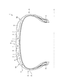
図1は、タイヤの子午断面図である。タイヤ1は、回転軸(Y軸)を中心として回転する環状構造体であり、回転軸の周りに、周方向に向かって同様の形状の子午断面が展開される。図1に示すように、タイヤ1の子午断面には、カーカス2、ベルト3、ベルトカバー4、ビードコア5が現れている。タイヤ1は、母材であるゴムを、補強材であるカーカス2、ベルト3、あるいはベルトカバー4等の補強コードによって補強した複合材料の構造体である。カーカス2、ベルト3、ベルトカバー4等の、金属繊維や有機繊維等のコード材料で構成される補強コードの層をコード層という。
FIG. 1 is a meridional sectional view of a tire. The tire 1 is an annular structure that rotates about a rotation axis (Y axis), and a meridional section having a similar shape is developed around the rotation axis in the circumferential direction. As shown in FIG. 1, a carcass 2, a
カーカス2は、タイヤ1に空気を充填した際に圧力容器としての役目を果たす強度メンバーであり、その内圧によって荷重を支え、走行中の動的荷重に耐えるようになっている。ベルト3は、キャップトレッド6とカーカス2との間に配置されたゴム引きコードを束ねた補強コードの層である。ラジアルタイヤにおいて、ベルト3は形状保持および強度メンバーとして重要な役割を担っている。
The carcass 2 is a strength member that serves as a pressure vessel when the tire 1 is filled with air. The carcass 2 supports a load by its internal pressure and withstands a dynamic load during traveling. The
ベルト3の踏面G側には、ベルトカバー4が配置されている。ベルトカバー4は、ベルト3の保護層としての役割や、ベルト3の補強層としての役割を持つ。ビードコア5は、内圧によってカーカス2に発生するコード張力を支えているスチールワイヤの束である。ビードコア5は、カーカス2、ベルト3、ベルトカバー4およびトレッドとともに、タイヤ1の強度部材となる。キャップトレッド(タイヤトレッド部)6の踏面G側には、溝(周溝、主溝)7が形成される。これによって、雨天走行時の排水性を向上させる。また、キャップトレッド6は、溝7とタイヤ幅方向に形成された溝(横溝)により分割され、ブロックが周方向に隣接した所定のパターンで形成される。また、タイヤ1の側部はサイドウォール8と呼ばれており、ビードコア5とキャップトレッド6との間を接続する。また、キャップトレッド6とサイドウォール8との間はショルダー部Shである。次に、本実施形態に係るタイヤのシミュレーション方法を実行する装置について説明する。
A belt cover 4 is disposed on the tread surface G side of the
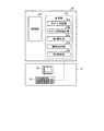
図2は、本実施形態に係るタイヤのシミュレーション方法を実行する解析装置を示す説明図である。本実施形態に係るタイヤのシミュレーション方法は、図2に示す解析装置50によって実現できる。解析装置50はコンピュータであり、図2に示すように、処理部52と記憶部54とで構成される。また、この解析装置50には、入出力装置51が電気的に接続されている。入出力装置51は、入力手段53を有している。この入力手段53は、タイヤを構成するゴムの物性値や補強コードの物性値、あるいは接地解析、剛性解析等に用いる境界条件等を処理部52や記憶部54へ入力する。
FIG. 2 is an explanatory diagram illustrating an analysis apparatus that executes the tire simulation method according to the present embodiment. The tire simulation method according to the present embodiment can be realized by the
入力手段53には、キーボード、マウス等の入力デバイスを使用することができる。記憶部54には、タイヤの解析(接地解析や転動解析、あるいは振動解析等)や本実施形態に係るタイヤのシミュレーション方法を含むコンピュータプログラムが格納されている。記憶部54は、ハードディスク装置や光磁気ディスク装置、又はフラッシュメモリ等の不揮発性のメモリ(CD−ROM等のような読み出しのみが可能な記憶媒体)や、RAM(Random Access Memory)のような揮発性のメモリ、あるいはこれらの組み合わせにより構成することができる。
An input device such as a keyboard and a mouse can be used for the input means 53. The
上記コンピュータプログラムは、コンピュータシステムに既に記録されているコンピュータプログラムとの組み合わせによって、接地解析や転動解析、あるいは本実施形態に係るタイヤのシミュレーション方法を実現できるものであってもよい。ここでいう「コンピュータシステム」とは、OS(Operating System)や周辺機器などのハードウェアを含むものとする。 The computer program may be capable of realizing the ground contact analysis, the rolling analysis, or the tire simulation method according to the present embodiment, in combination with a computer program already recorded in the computer system. The “computer system” here includes hardware such as an OS (Operating System) and peripheral devices.
処理部52は、モデル作成部52aと、モデル領域設定部52bと、第1解析部52cと、剛体設定部52dと、第2解析部52eと、を含む。モデル作成部52aは、解析対象のタイヤを、複数の節点を有する複数の要素に分割して、解析に供する解析モデルを作成し、記憶部54に保存する。なお、モデル作成部52aは、剛性を解析する条件、モデルに基づいて決定される種々の部材をモデル化する。例えば、解析対象のタイヤのモデル(タイヤモデル)や、タイヤに嵌め込むホイールのモデル(ホイールモデル)、タイヤが接触する路面のモデル(路面モデル)を作成する。また、解析対象のタイヤのモデルは、タイヤ全体のモデルを作成する。具体的には、タイヤの路面接触時の剛性を検出する場合も、タイヤの接触領域、例えばタイヤトレッド部のブロックだけではなく、接触していない領域の部分も備えるモデルを作成する。
The
モデル領域設定部52bは、モデル作成部52aで作成したタイヤモデルを、解析対象とする領域と、その他の領域と、に分ける境界を設定する。なお、モデル領域設定部52bが設定する境界は、作成された解析モデルに対してユーザが操作を入力することで決定しても、予め設定された条件に基づいて決定してもよい。
The model region setting unit 52b sets a boundary that divides the tire model created by the
第1解析部52cは、モデル作成部52aが作成した解析モデルを記憶部54から読み出し、所定の条件の下で変形解析を実行する。なお、変形解析としては、作成したタイヤモデルが変形する種々の要因の変形解析が対象となる。具体的には、第1解析部52cは、タイヤを路面に接触させることで発生する変形を解析したり、タイヤをインフレートさせることで発生する変形を解析したり、タイヤをホイールに装着させることで発生する変形を解析したりする。
The
剛体設定部52dは、モデル領域設定部52bで設定した領域に基づいて、第1解析部52cで変形解析した解析モデルのタイヤモデルのその他の領域の少なくとも一部を略剛体として設定する。つまり、剛体設定部52dは、第1解析部52cで算出した形状のタイヤモデルを対象として、その他の領域の少なくとも一部の弾性体を剛体に置き換える処理を行う。ここで、剛体設定部52dは、タイヤモデルの解析対象となる領域とその他の領域との境界線を少なくとも含む領域を剛体に置き換える。なお、タイヤモデルの所定の領域を略剛体に変換する方法としては、弾性率をゴム材料に対して非常に高いものに変更する処置、該当する節点集合の相対変位が変わらないようにする処理等が例示される。
Based on the region set by the model region setting unit 52b, the rigid
第2解析部52eは、第1解析部52cで算出された変形後の形状であり、かつ、剛体設定部52dで少なくとも一部が剛体に置き換えられたタイヤモデルを含む解析モデルを解析して、解析対象の領域の剛性を算出する。具体的には、第2解析部52eは、解析モデルのタイヤモデルに相対変位および外力を与え、その状態でタイヤモデルの各要素に発生する反力および変位を算出する。その後、算出した各要素に発生する反力および変位に基づいて解析対象の領域の剛性を算出する。
The
なお、モデル作成部52aとモデル領域設定部52bと第1解析部52cと、剛体設定部52dと第2解析部52eとは、解析モデルや条件や解析結果を算出、毛低したら、決定した各結果を記憶部54の所定領域に格納する。また、各部は、記憶部54に格納された各結果を用いて、解析、作成を実行する。
The
処理部52は、例えば、メモリおよびCPU(Central Processing Unit)により構成されている。解析時においては、モデル作成部52aが作成した解析モデルや入力データ等に基づいて、処理部52が前記プログラムを処理部52に組み込まれたメモリに読み込んで演算する。その際に処理部52は、記憶部54へ演算途中の数値を適宜格納し、また記憶部54へ格納した数値を取り出して演算を進める。なお、この処理部52は、前記コンピュータプログラムの代わりに専用のハードウェアによって、その機能を実現するものであってもよい。
The
表示手段55は、例えば、液晶表示装置等の表示用デバイスである。記憶部54は、他の装置(例えばデータベースサーバ)内にあってもよい。例えば、解析装置50は、入出力装置51を備えた端末装置から通信により処理部52や記憶部54にアクセスするものであってもよい。次に、本実施形態に係るタイヤのシミュレーション方法を説明する。なお、本実施形態に係るタイヤのシミュレーション方法は、上述した解析装置50により実現できる。
The display means 55 is a display device such as a liquid crystal display device. The
次に、図3から図5を用いて本実施形態のシミュレーション方法についてより詳細に説明する。図3は、本実施形態に係るタイヤのシミュレーション方法の手順を示すフローチャートである。図4は、解析モデルに含まれるタイヤモデルの一例を示す部分斜視図である。図5は、本実施形態に係るタイヤのシミュレーション方法の手順を模式的に示す説明図である。なお、図3から5に示すシミュレーション方法は、上述した処理部52の各部で処理を実行することで実現される。また、処理部52は、記憶部54に記憶されたプログラムや条件、入力手段53で検出した入力を用いて各処理を実行する。また、図3から図5に示すシミュレーション方法は、タイヤを路面に接地(接触)させた場合のタイヤの接触領域の剛性を解析する例である。
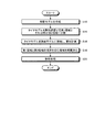
Next, the simulation method of the present embodiment will be described in more detail with reference to FIGS. FIG. 3 is a flowchart showing the procedure of the tire simulation method according to the present embodiment. FIG. 4 is a partial perspective view showing an example of a tire model included in the analysis model. FIG. 5 is an explanatory diagram schematically showing a procedure of the tire simulation method according to the present embodiment. The simulation method shown in FIGS. 3 to 5 is realized by executing processing in each unit of the
まず、図2に示す解析装置50の処理部52は、ステップS12として、モデル作成部52aにより解析モデルを作成する。モデル作成部52aは、作成した解析モデルを記憶部54の所定領域に保存する。具体的には、解析対象であるタイヤのモデルを含む解析モデルを作成する。ここで、解析モデルは、有限要素法(Finite Element Method:FEM)や有限差分法(Finite Differences Method:FDM)等の数値解析手法を用いてコンピュータが変形解析および剛性解析を実行するために用いるモデルであって、コンピュータで解析可能である。解析モデルは、数学的モデルや数学的離散化モデルを含む。ステップS12で作成される解析モデルのうちタイヤモデルは、図4に示すタイヤモデル62である。なお、図4に示すようにタイヤモデル62は、外周面にタイヤトレッド部72が形成されている。上述したように、タイヤトレッド部72は、走行時に路面と接触する面であり、本実施形態では、主溝および横溝により複数に分割された複数のブロックが形成されている。本実施形態では、解析モデルの解析に有限要素法を使用するので、解析モデルは、有限要素法に基づいて作成される。
First, the
本実施形態に係る解析に適用できる解析手法は有限要素法に限られず、有限差分法や境界要素法(Boundary Element Method:BEM)等の解析手法も使用できる。また、境界条件等によって最も適当な解析手法を選択し、又は複数の解析手法を組み合わせて使用することもできる。なお、有限要素法は、構造解析に適した解析手法なので、特にタイヤのような構造体に対して好適である。 An analysis method applicable to the analysis according to the present embodiment is not limited to the finite element method, and an analysis method such as a finite difference method or a boundary element method (BEM) can also be used. Further, the most appropriate analysis method can be selected according to the boundary condition or the like, or a plurality of analysis methods can be used in combination. The finite element method is an analysis method suitable for structural analysis, and is particularly suitable for a structure such as a tire.
モデル作成部52aは、例えば、解析対象のタイヤのCAD(Computer Aided Design)用のデータから、解析モデルを作成する。有限要素法に基づいて解析モデルが作成される場合、モデル作成部52aは、CAD用データによって特定されるタイヤを、複数かつ有限個の要素に分割して、解析モデル10を作成する。本実施形態では、解析モデルのタイヤモデルを、それぞれ3次元形状の解析モデルとして作成する。
For example, the
解析モデルが有する要素は、例えば、3次元の解析モデルでは四面体ソリッド要素、五面体ソリッド要素、六面体ソリッド要素等のソリッド要素や三角形シェル要素、四角形シェル要素等のシェル要素、面要素等、コンピュータで取り扱い得る要素とすることが望ましい。このようにして分割された要素は、解析の過程においては、3次元の解析モデルでは3次元座標や円筒座標を用いて逐一特定される。 The elements of the analysis model include, for example, solid elements such as tetrahedral solid elements, pentahedral solid elements, hexahedral solid elements, shell elements such as triangular shell elements, quadrilateral shell elements, plane elements, etc. It is desirable to make it an element that can be handled with. In the process of analysis, the elements divided in this way are identified one by one using three-dimensional coordinates and cylindrical coordinates in a three-dimensional analysis model.
解析装置50の処理部52は、ステップS12で解析モデルを作成したら、ステップS14として、モデル領域設定部52bによりタイヤモデルを剛性評価する第1領域と、それ以外の第2領域とに分割する。つまり、モデル領域設定部52bは、作成した解析モデルのタイヤモデルを解析対象の領域と、その他の領域とに分ける。具体的に、タイヤモデルの接地領域およびその近傍を第1領域とし、タイヤモデルのその他の領域を第2領域として、第1領域と第2領域の境界を設定する。モデル領域設定部52bは、設定した境界の情報を記憶部54の所定領域に保存する。
After creating the analysis model in step S12, the
解析装置50の処理部52は、ステップS14でタイヤモデルを第1領域と第2領域とに分割したら、ステップS16として、第1解析部52cによりタイヤモデルを路面モデルに接地させ、変形計算(変形解析)を行う。つまり、第1解析部52cは、タイヤモデルが路面モデルに接地した場合にタイヤモデルに発生する変形を計算する、つまり接地解析を行う。なお、接地圧等の接地条件は予め設定されている。第1解析部52cは、解析結果(各節点の座標や物理量等)を記憶部54の所定領域に保存する。接地解析とは、タイヤモデルと路面との動的、又は静的な接触状態において、少なくともタイヤモデルの変形やひずみ、あるいは応力の状態を解析するものである。
When the tire model is divided into the first region and the second region in step S14, the
解析装置50の処理部52は、ステップS16で接地状態の変形計算を行ったら、ステップS18として剛体設定部52dにより第1領域と第2領域との境界を含む部分を略剛体化する。つまり、剛体設定部52dは、第1解析部52cで算出した接地により変形したタイヤモデルの一部を、モデル領域設定部52bで設定した領域および境界の情報に基づいて略剛体化する。具体的には、タイヤモデルのうち、第1領域に含まれず、かつ、少なくとも第1領域と第2領域との境界を含む領域を略剛体に置換する。
When the
解析装置50の処理部52は、ステップS18で少なくとも境界を含む領域を略剛体としたら、ステップS20として、第2解析部52eにより解析処理を行う。具体的には、第2解析部52eは、ステップS18で一部を略剛体としたタイヤモデルに相対変位・外力を付与し、相対変位・外力を付与することで、発生するタイヤモデルの各部(第1領域の各部)の反力・変位を算出する。第2解析部52eは、算出したタイヤモデルの各部の反力・変位に基づいて各部の剛性を算出する。解析装置50の処理部52は、解析処理を行い、剛性を算出したら、本処理を終了する。
When the
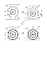
以下、図5を用いてシミュレーション方法による解析モデルの遷移状態を説明する。処理部52は、タイヤモデル62と路面モデル64とを含む解析モデル60aを作成する。タイヤモデル62は、タイヤの全体(全周)を模したモデルであり、路面と接触する領域であるタイヤトレッド部72(単に「トレッド部」ともいう。)と、タイヤトレッド部72よりもタイヤ径方向内側の領域であるタイヤサイド部(単に「サイド部」ともいう。)74と、を有する。
Hereinafter, the transition state of the analysis model according to the simulation method will be described with reference to FIG. The
処理部52は、解析モデル60aに示すように、解析対象の領域を特定し、タイヤモデルを解析対象の領域(第1領域)と、その他の領域(第2領域)とに分ける。ここで、図5に示す例は、タイヤトレッド部72の接地領域の剛性を算出する場合の例である。処理部52は、タイヤトレッド部72を、路面モデル64と接触する部分とその周辺部分とを含む領域76と、それ以外の領域(路面モデル64から離れている領域)78と、に分ける。また、サイド部74は、全ての領域が解析対象ではない領域となる。処理部52は、以上のようにしてタイヤモデル62を解析対象の第1領域である領域76と第2領域である領域78およびサイド部74とに分ける。なお、処理部52は、領域76と領域78との間および領域76とサイド部74との間に境界を設けることで、領域76とその他の領域とを分ける。
As shown in the
処理部52は、解析対象の領域を特定し、当該領域とその他の領域とを境界で分けたら、解析モデル60bに示すように、タイヤモデル62を路面モデル64に接地させた状態とし、路面モデル64に接触したタイヤモデル62の変形計算を行う。なお、タイヤモデル62は、領域76の一部が路面モデル64と接触している。
When the
処理部52は、接触解析を行ったら、解析モデル60cに示すように、接触解析を行ったタイヤモデル62を、第1領域82と第2領域84とに分け、第2領域84を略剛体とする。なお、第1領域82の設定は変更しない。ここで、第1領域82は、タイヤトレッド部72でありゴム等で構成されているため弾性体となる。
After performing the contact analysis, the
処理部52は、第2領域84を略剛体としたら、解析モデル60dに示すように、路面モデル64に変位86を与え、タイヤモデル62と路面モデル64の相対位置を変化させ、その際に、第1領域82の各部に生じる反力および変位を算出する。その後、処理部52は、算出した第1領域82の反力および変位に基づいて、第1領域82の各部の剛性を算出する。なお、処理部52は、種々の単位で剛性を算出することができ、例えば、第1領域82の要素毎、一定要素単位、タイヤトレッド部のブロック単位、第1領域82全体を、算出の単位として剛性を算出することができる。また、剛性は、例えば変位と力の関係から算出することができる。
If the
解析装置50は、本実施形態のシミュレーション方法により第1領域82を弾性体のままとしつつ、第2領域84を略剛性とすることで、解析対象の第1領域82の剛性を適切に評価することができる。つまり、第2領域を略剛体とすることで、剛性算出時に第2領域に変形、反力が生じることを抑制できるため、第1領域82の剛性を適切に算出することができる。
The
なお、図5に示す実施形態では、第2領域84の全域を剛体としたが、少なくとも第1領域と第2領域との境界を略剛体とすればよい。つまり、第1領域と第2領域との境界を含み、かつ、第1領域を含まない領域を剛体とすればよい。このように少なくとも境界を剛体とすることで、第1領域の剛性を的確に算出することができる。つまり、第1領域と第2領域との境界を略剛体とすることで、第2領域の剛性が第1領域に影響することを抑制することができ、第1領域の剛性を的確に算出することができる。
In the embodiment shown in FIG. 5, the entire region of the
解析装置50は、本実施形態のシミュレーション方法によりタイヤモデルの変形を算出した後に少なくとも境界を含む領域を剛体とすることで、解析対象である第1領域をより的確な形状とした後に、剛性を算出することができる。例えば、第1領域のみをモデル化して剛性を解析する場合は、第1領域以外の領域から受ける影響を加味することなく、形状を算出することになるため、実際の形状とは異なる形状となる恐れがある。これに対して、解析装置50は、変形計算をした後に境界を含む所定領域を剛体とすることで、解析対象の条件の場合の第1領域の形状をより正確に算出することができる。第1領域をより正確な形状にできるため、計測条件に対応した第1領域の剛性をより正確に算出することができる。
The
また、解析装置50は、上記実施形態のように、第2領域の全域を略剛体とすることが好ましい。第2領域の全域を略剛体とすることで、剛性の算出時の計算対象を第1領域のみとすることができる。これにより、計算量をより少なくすることができる。また、解析装置50は、剛性の計算時は、第1領域のみを計算の対象としてもよい。
Moreover, as for the
また、解析装置50は、少なくとも境界を含む領域を略剛体とする方法としては、種々の方法を用いることができるが、力を与えてタイヤモデルを変形させ、弾性率を変えて略剛体にする場合、力を変位に換算して、変位を与える処理を行うことが好ましい。これにより、変形させたタイヤの変形状態が剛性算出時に変形することを抑制することができる。
The
また、上記実施形態では、タイヤモデルの全体を変形解析の対象としたがこれにも限定されない。解析装置50は、第2領域の少なくとも一部と、第1領域とを対象として変形解析を行えばよい。このように、解析装置50は、タイヤの一部を変形させても、タイヤの全体を変形させてもよい。
Moreover, in the said embodiment, although the whole tire model was made into the object of a deformation | transformation analysis, it is not limited to this. The
また、第1領域であり、かつ、路面モデルと接触領域の少なくとも一部に摩擦係数を設定する(摩擦係数を0より大きくする)ことが好ましい。これにより剛性を適切に算出することができる。なお、摩擦係数を設定する領域は、第1領域の全体でも、一部でもよい。また、第2領域は、摩擦係数を設定しない(摩擦係数を0)とすることで、解析対象から外すことができる。 In addition, it is preferable that the friction coefficient is set in at least a part of the road surface model and the contact area (the friction coefficient is made larger than 0) in the first area. Thereby, rigidity can be calculated appropriately. The region for setting the friction coefficient may be the entire first region or a part thereof. Further, the second region can be excluded from the analysis target by not setting the friction coefficient (the friction coefficient is 0).
また、図5に示す例のように、第1領域にタイヤトレッド部の接地領域を含むことで、接地したタイヤのパターン剛性を知ることができる。なお、タイヤトレッド部の第2領域に含まれる領域78は、タイヤトレッド部の第1領域に含まれる領域76よりも簡略化したモデル化をしてもよい。これにより計算量を低減することができる。また、第2領域のタイヤトレッド部を簡略化した場合も第1領域の変形計算は、高精度に実行することができる。また、タイヤトレッド部は周方向主溝のみをモデル化してもよく、詳細なパターンをモデル化してもよい。
Further, as in the example shown in FIG. 5, the pattern rigidity of the grounded tire can be known by including the ground contact area of the tire tread portion in the first area. The
また、図5に示す例では、剛性の算出時に付与する相対変位を一方向の変位としたが、相対変位の方向は複数あってもよい。また、図5に示す例では、相対変位を付与して剛性を算出したが、剛性の算出方法はこれに限定されない。例えば、タイヤモデルの外力を付与して、その際の反力、変位を算出し、その結果に基づいて剛性を算出してもよい。 In the example shown in FIG. 5, the relative displacement applied at the time of calculating the stiffness is assumed to be one-direction displacement, but there may be a plurality of relative displacement directions. In the example shown in FIG. 5, the rigidity is calculated by applying a relative displacement, but the rigidity calculation method is not limited to this. For example, the external force of the tire model may be applied, the reaction force and displacement at that time may be calculated, and the stiffness may be calculated based on the result.
また、路面モデルは、平板のモデルに限定されない。路面モデルは、凹凸を有してもよく、ドラム形状を模した形状でもよい。また、タイヤモデルと路面モデルと変形解析時および剛性の解析時の摩擦条件は、固着とする設定でも、摩擦係数としてクーロン摩擦あるいは圧力やすべり依存を有する設定としてもよい。また、剛性の解析時は、剛性を評価しない部分、つまり、第2領域については、摩擦を考慮しなくてもよい。 The road surface model is not limited to a flat plate model. The road surface model may have irregularities and may have a shape imitating a drum shape. Further, the friction conditions during the tire model, the road surface model, the deformation analysis, and the stiffness analysis may be set to be fixed, or may be set to have a Coulomb friction or a pressure or slip dependency as a friction coefficient. Further, at the time of analyzing the stiffness, it is not necessary to consider the friction for the portion where the stiffness is not evaluated, that is, the second region.
また、図5に示す例では、解析モデルをタイヤモデルと路面モデルとを含む構成としたが、これに限定されない。例えば、ホイールモデルを設け、タイヤモデルとホイールモデルとを組み合わせた構成としてもよい。なお、タイヤモデルとホイールモデルと組み合わせる前は、変形解析として、接地変形の前にタイヤモデルとホイールモデルの嵌合による変形計算、タイヤのインフレートによる変形計算を行ってもよい。このように、タイヤモデルとホイールモデルの嵌合や、タイヤのインフレートに基づく変形を考慮することで、剛性の解析時のタイヤモデルの解析対象の領域の形状をより正確な形状とすることができる。 In the example shown in FIG. 5, the analysis model includes a tire model and a road surface model, but is not limited thereto. For example, a wheel model may be provided and a tire model and a wheel model may be combined. Before the tire model and the wheel model are combined, as a deformation analysis, a deformation calculation by fitting the tire model and the wheel model or a deformation calculation by inflation of the tire may be performed before the ground deformation. In this way, by considering the fitting between the tire model and the wheel model and the deformation based on the inflation of the tire, it is possible to make the shape of the analysis target region of the tire model more accurate when analyzing the rigidity. it can.
なお、上記実施形態では、タイヤトレッド部の接地領域を第1領域としたが、本発明はこれに限定されない。第1領域としてはタイヤの種々の部分を設定することができる。例えば、タイヤのタイヤトレッド部全体を第1領域としてもよいし、タイヤのサイド部の全部または一部を第1領域としてもよい。また、上記実施形態ではタイヤをタイヤトレッド部とサイド部の2つに分けた場合としたが、タイヤの領域の分割方法は特に限定されず剛性の解析の用途等に応じて適宜領域を設定すればよい。また、タイヤ幅方向の領域によって、第1領域と第2領域を分けておよい。例えば、タイヤトレッド部の接地領域のうち、センター側のブロックのみを第1領域(剛性を算出する部分)としてもよいし、ショルダー部のブロックのみを第1領域としてもよい。また、リブごとの第1領域か否かを設定しても、パターンを構成する一部の要素毎に第1領域か否かを設定してもよい。 In the above embodiment, the ground contact area of the tire tread portion is the first area, but the present invention is not limited to this. Various portions of the tire can be set as the first region. For example, the entire tire tread portion of the tire may be the first region, or all or part of the side portion of the tire may be the first region. In the above embodiment, the tire is divided into the tire tread portion and the side portion. However, the method for dividing the tire region is not particularly limited, and the region may be appropriately set according to the use of the stiffness analysis. That's fine. Further, the first region and the second region may be divided according to the region in the tire width direction. For example, in the ground contact area of the tire tread portion, only the center side block may be set as the first area (a part for calculating rigidity), or only the shoulder block may be set as the first area. Moreover, even if it is set whether it is the 1st area | region for every rib, you may set whether it is the 1st area | region for every one part element which comprises a pattern.
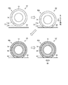
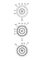
次に、図6を用いて、シミュレーション方法の他の実施形態について説明する。ここで、図6は、本実施形態に係るタイヤのシミュレーション方法の手順を模式的に示す説明図である。なお、図6に示すシミュレーション方法は、タイヤサイド部を第1領域とした場合の実施形態である。まず、処理部52は、タイヤモデル104と路面モデル106とホイールモデル108とを含む解析モデル102aを作成する。タイヤモデル104は、タイヤの全体(全周)を模したモデルであり、路面と接触する領域であるタイヤトレッド部110と、タイヤトレッド部110よりもタイヤ径方向内側の領域であるタイヤサイド部112と、径方向内側の端部でありホイールモデル108と接触するリム接触部114と、を有する。つまりタイヤモデルは、タイヤ径方向外側から内側にタイヤトレッド部110、タイヤサイド部112、リム接触部114の順で形成されている。またリム接触部114がホイールモデル108と接触する。また、解析モデル102aは、タイヤモデル104とホイールモデル108とのタイヤ径方向の中心を参照点116とする。
Next, another embodiment of the simulation method will be described with reference to FIG. Here, FIG. 6 is an explanatory view schematically showing the procedure of the tire simulation method according to the present embodiment. Note that the simulation method shown in FIG. 6 is an embodiment in which the tire side portion is the first region. First, the
処理部52は、解析モデル102aに示すように、解析対象の領域を特定し、タイヤモデルを解析対象の領域(第1領域)と、その他の領域(第2領域)とに分ける。ここで、図5に示す実施形態は、タイヤトレッド部110のタイヤサイド部112の剛性を算出する場合の実施形態である。処理部52は、タイヤサイド部112を解析対照の領域と設定し、タイヤトレッド部110とリム接触部114とを解析対象ではない領域と設定する。処理部52は、以上のようにしてタイヤモデル104を解析対象の第1領域であるタイヤサイド部112と第2領域であるタイヤトレッド部110及びリム接触部114とに分ける。なお、処理部52は、タイヤトレッド部110とタイヤサイド部112の間およびタイヤサイド部112とリム接触部114との間に境界を設けることで、タイヤサイド部112とその他の領域とを分ける。
As shown in the
処理部52は、解析対象の領域を特定し、当該領域とその他の領域とを境界で分けたら、解析モデル102bに示すように、タイヤモデル104を路面モデル106に接地させた状態とし、路面モデル106に接触したタイヤモデル104の変形計算を行う。また、処理部52は、路面モデル106に接触したタイヤモデル104の変形計算を行う前に、タイヤモデル104とホイールモデルの嵌合により生じる変形計算や、タイヤモデル104をインフレートさせた場合に生じる変形計算を行ってもよい。
The
処理部52は、接触解析を行ったら、解析モデル102cに示すように、接触解析を行ったタイヤモデル104を、第1領域と第2領域とに分け、第1領域と第2領域との境界を略剛体とする。なお、第1領域の設定は変更しない。ここで、本実施形態では、処理部52は、タイヤサイド部112が第1領域をとし、その他の領域を第2領域とする。また、処理部52は、タイヤトレッド部110のうち、タイヤサイド部112との境界を含む領域120を略剛体とし、リム接触部114の全域を含む領域122を略剛体とする。なお、第1領域は、タイヤサイド部112でありゴム等で構成されているため弾性体となる。
After performing the contact analysis, the
処理部52は、領域120と領域122とを略剛体としたら、解析モデル102dに示すように、タイヤモデル104の参照点116に対して変位126を与え、タイヤモデル104とホイールモデル108との相対位置を変化させ、その際に、第1領域(タイヤサイド部112)の各部に生じる反力および変位を算出する。その後、処理部52は、算出した第1領域の反力および変位に基づいて、第1領域の各部の剛性を算出する。
If the
解析装置50は、図6に示すように、タイヤが路面に接地した状態のおけるタイヤサイド部の剛性を算出することもできる。この場合も、タイヤモデルの変形計算を行った後に、第1領域と第2領域の境界である領域120と領域122とを略剛体とすることで、第1領域であるタイヤサイド部の剛性をより高い精度で解析することができる。
As shown in FIG. 6, the
なお、図6に示す実施形態では、第2領域のうち、境界を含む一部のみを略剛体としたが、全域を剛体としてもよい。 In the embodiment shown in FIG. 6, only a part of the second region including the boundary is substantially rigid, but the entire region may be rigid.
次に、図7および図8を用いて、シミュレーション方法の他の実施形態について説明する。ここで、図7は、本実施形態に係るタイヤのシミュレーション方法の手順を示すフローチャートである。図8は、本実施形態に係るタイヤのシミュレーション方法の手順を模式的に示す説明図である。なお、図7および図8に示すシミュレーション方法は、変形計算として路面との接触により生じる変形以外の変形を対象とした場合の実施形態である。 Next, another embodiment of the simulation method will be described with reference to FIGS. FIG. 7 is a flowchart showing the procedure of the tire simulation method according to this embodiment. FIG. 8 is an explanatory diagram schematically showing a procedure of the tire simulation method according to the present embodiment. The simulation method shown in FIGS. 7 and 8 is an embodiment in the case where deformation other than deformation caused by contact with the road surface is targeted for deformation calculation.
まず、解析装置50の処理部52は、ステップS32として、モデル作成部52aにより解析モデルを作成する。モデル作成部52aは、作成した解析モデルを記憶部54の所定領域に保存する。解析装置50の処理部52は、ステップS32で解析モデルを作成したら、ステップS34として、モデル領域設定部52bによりタイヤモデルを剛性評価する第1領域と、それ以外の第2領域とに分割する。モデル領域設定部52bは、設定した境界の情報を記憶部54の所定領域に保存する。
First, the
解析装置50の処理部52は、ステップS34でタイヤモデルを第1領域と第2領域とに分割したら、ステップS36として、第1解析部52cによりタイヤモデルの変形計算(変形解析)を行う。ここで、第1解析部52cは、変形計算として、タイヤモデルをホイールモデルに嵌め込む(嵌合させる)ことで生じる変形や、タイヤモデルをインフレートさせることで生じる変形を計算する。第1解析部52cは、解析結果(各節点の座標や物理量等)を記憶部54の所定領域に保存する。
When the
解析装置50の処理部52は、ステップS36で変形計算を行ったら、ステップS38として剛体設定部52dにより第1領域と第2領域との境界を含む部分を略剛体化する。つまり、剛体設定部52dは、第1解析部52cで算出した接地により変形したタイヤモデルの一部を、モデル領域設定部52bで設定した領域および境界の情報に基づいて略剛体化する。
After performing the deformation calculation in step S36, the
解析装置50の処理部52は、ステップS38で少なくとも境界を含む領域を略剛体としたら、ステップS20として、第2解析部52eにより解析処理を行う。具体的には、第2解析部52eは、ステップS38で一部を略剛体としたタイヤモデルに相対変位・外力を付与し、相対変位・外力を付与することで、発生するタイヤモデルの各部(第1領域の各部)の反力・変位を算出する。第2解析部52eは、算出したタイヤモデルの各部の反力・変位に基づいて各部の剛性を算出する。解析装置50の処理部52は、解析処理を行い、剛性を算出したら、本処理を終了する。
When the
以下、図8を用いてシミュレーション方法による解析モデルの遷移状態を説明する。まず、処理部52は、タイヤモデル134とホイールモデル136とを含む解析モデル132aを作成する。タイヤモデル134は、タイヤの全体(全周)を模したモデルであり、路面と接触する領域であるタイヤトレッド部140と、タイヤトレッド部140よりもタイヤ径方向内側の領域であるタイヤサイド部142と、径方向内側の端部でありホイールモデル136と接触するリム接触部144と、を有する。つまりタイヤモデルは、タイヤ径方向外側から内側にタイヤトレッド部140、タイヤサイド部142、リム接触部144の順で形成されている。またリム接触部144がホイールモデル136と接触する。また、解析モデル132aは、タイヤモデル134とホイールモデル136とのタイヤ径方向の中心を参照点146とする。
Hereinafter, the transition state of the analysis model according to the simulation method will be described with reference to FIG. First, the
処理部52は、解析モデル132aに示すように、解析対象の領域を特定し、タイヤモデルを解析対象の領域(第1領域)と、その他の領域(第2領域)とに分ける。ここで、図8に示す実施形態は、タイヤトレッド部140のタイヤサイド部142の剛性を算出する場合の実施形態である。処理部52は、タイヤサイド部142を解析対照の領域と設定し、タイヤトレッド部140とリム接触部144とを解析対象ではない領域と設定する。処理部52は、以上のようにしてタイヤモデル134を解析対象の第1領域であるタイヤサイド部142と第2領域であるタイヤトレッド部140とリム接触部144とに分ける。なお、処理部52は、タイヤトレッド部140とタイヤサイド部142の間およびタイヤサイド部142とリム接触部144との間に境界を設けることで、タイヤサイド部142とその他の領域とを分ける。
As shown in the
処理部52は、解析対象の領域を特定し、当該領域とその他の領域とを境界で分けたら、タイヤモデル134の変形計算を行う。タイヤモデル134の変形計算としては、タイヤモデル134とホイールモデルの嵌合により生じる変形計算や、タイヤモデル134をインフレートさせた場合に生じる変形計算等が例示される。タイヤモデル134の変形計算を行うことで、タイヤサイド部142は、変形したり付与される力が変化したりする。
The
処理部52は、変形計算を行ったら、解析モデル132bに示すように、変形計算を行ったタイヤモデル134を、第1領域と第2領域とに分け、第1領域と第2領域との境界を略剛体とする。なお、第1領域の設定は変更しない。ここで、本実施形態では、処理部52は、タイヤサイド部142が第1領域をとし、その他の領域を第2領域とする。また、処理部52は、タイヤトレッド部140のうち、タイヤサイド部142との境界を含む領域150を略剛体とし、リム接触部144の全域を含む領域152を略剛体とする。なお、第1領域は、タイヤサイド部142でありゴム等で構成されているため弾性体となる。
When the deformation calculation is performed, the
処理部52は、領域150と領域152とを略剛体としたら、解析モデル132cに示すように、タイヤモデル134の参照点146に対して変位156を与え、タイヤモデル134とホイールモデル136との相対位置を変化させ、その際に、第1領域(タイヤサイド部142)の各部に生じる反力および変位を算出する。その後、処理部52は、算出した第1領域の反力および変位に基づいて、第1領域の各部の剛性を算出する。
When the
解析装置50は、図8に示すように、タイヤが路面に接地していない状態のおけるタイヤサイド部の剛性を算出することもできる。このように、接地していない場合であってもタイヤモデルの変形計算で第1領域の形状をより正確に算出したタイヤモデルを用いて剛性の解析を行うことで、より正確な剛性を算出することができる。
As shown in FIG. 8, the
次に、図9及び図10を用いて、第1領域の設定の他の実施形態を説明する。ここで、図9および図10は、それぞれタイヤの解析対象の領域の設定の他の例を示す説明図である。図9および図10は、タイヤモデルのタイヤトレッド部の幅方向の位置によって、第1領域と第2領域とを分ける場合の実施形態である。また、図9および図10は、タイヤモデルのタイヤトレッド部のうち、路面モデルと接触する領域を示している。 Next, another embodiment of setting the first region will be described with reference to FIGS. 9 and 10. Here, FIG. 9 and FIG. 10 are explanatory diagrams showing other examples of setting the analysis target region of the tire. 9 and 10 show an embodiment in which the first region and the second region are divided according to the position in the width direction of the tire tread portion of the tire model. 9 and 10 show a region in contact with the road surface model in the tire tread portion of the tire model.
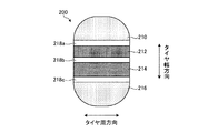
図9に示すタイヤモデル200は、タイヤトレッド部の接触領域が、陸部(ブロック部)210、212、214、216と、溝218a、218b、218cと、で構成されている。ここで、溝218a、218b、218cは、タイヤ周方向に延在する凹部であり、タイヤトレッド部の陸部を複数のブロックに分割している。陸部210は、タイヤ幅方向の一方の端部に配置されたブロックであり、タイヤ幅方向において、タイヤ中心側の端面が溝218aと接している。また、陸部212は、タイヤ幅方向において、一方の端面が溝218aと接し、他方の端部が溝218bと接している。このように陸部のうち溝218aと溝218bとで囲まれた部分が陸部212となる。また、陸部214は、タイヤ幅方向において、一方の端面が溝218bと接し、他方の端部が溝218cと接している。このように陸部のうち溝218bと溝218cとで囲まれた部分が陸部214となる。陸部216は、タイヤ幅方向の他方の端部に配置されたブロックであり、タイヤ幅方向において、タイヤ中心側の端面が溝218cと接している。このようにタイヤモデル200は、接触領域の陸部が陸部210、212、214、216の4つの陸部で構成される。
In the
このように陸部が複数のブロックで構成される場合、解析装置50は、タイヤモデルの陸部のブロック毎に、解析対象とするか否かを設定することができる。例えば、図9示すタイヤモデル200のように、陸部210と陸部216とを第1領域とし、陸部212と陸部214とを第2領域と設定することができる。また、この場合、陸部210と陸部216とは、路面モデルとの間の摩擦係数を0より大きい値とし、陸部212と陸部214とは、路面モデルとの間の摩擦係数を0とする。これにより、第1領域の陸部210と陸部216との剛性を好適に算出することができる。
When the land portion is configured by a plurality of blocks as described above, the
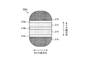
また、解析装置50は、図10に示すタイヤモデル200aのように、陸部212と陸部214とを第1領域とし、陸部210と陸部216とを第2領域と設定することもできる。なお、タイヤモデル200aは、第1領域および第2領域の設定がことなるのみで、モデルの形状は、タイヤモデル200と同様である。また、この場合、陸部212と陸部214とは、路面モデルとの間の摩擦係数を0より大きい値とし、陸部210と陸部216とは、路面モデルとの間の摩擦係数を0とする。これにより、第1領域の陸部212と陸部214との剛性を好適に算出することができる。
Moreover, the
このように、タイヤ幅方向の位置に応じて領域および境界を設定することで、より目的に応じた解析を効率よく行うことができる。例えば、タイヤ幅方向の特定の位置(特定のブロック)の剛性のみを知りたい場合は、そのブロックのみを第1領域とし、その他の領域を第2領域とすることで、当該ブロックの剛性を解析することができる。また、剛性解析時に第1領域の解析に必要な部分以外の第2の領域の要素については解析を実行しないことで、計算量も少なくすることができる。 As described above, by setting the region and the boundary according to the position in the tire width direction, it is possible to efficiently perform the analysis according to the purpose. For example, if you want to know only the rigidity of a specific position (specific block) in the tire width direction, analyze only the block as the first area and the other area as the second area. can do. Further, the amount of calculation can be reduced by not performing the analysis on the elements of the second region other than the portion necessary for the analysis of the first region during the rigidity analysis.
ここで、解析装置50は、タイヤトレッド部の摩耗による形状変化や経時変化による弾性率の変化を考慮したモデルを複数作成し計算することが好ましい。このように、複数のモデルを計算し、それぞれのモデルの剛性を算出することで、対象領域のタイヤトレッド部の剛性をより適切に実際の使用に則して評価することができる。
Here, it is preferable that the
また、解析装置50は、タイヤと路面とが接触する相対位置が異なる条件で変形計算を行った2つ以上の解析モデルを用いて、第1領域の剛性を算出することが好ましい。これにより、解析モデルの第1領域の剛性をより正確に算出することができる。例えば、タイヤが周方向の主溝以外の溝を有する場合、接地形状と溝位置の関係によって接地面の絵柄が変わり、タイヤトレッド部の剛性は変化する。このような場合に、タイヤと路面との相対位置を変化させた(タイヤトレッド部のパターンの長さより短い距離分相対位置を変化させた)複数の解析モデルを作成し、それぞれの解析モデルを比較した結果に基づいて、当該第1領域の剛性を算出することでより正確な剛性を算出することができる。解析装置50は、このように複数の解析モデルを用いる場合、複数の解析モデルのそれぞれについて変形計算を行い、その変形計算した結果に基づいて、解析モデルの変形状態を決定し、その決定した形状の解析モデルを用いて、剛性を算出すればよい。なお、2つ以上のタイヤ接地計算の結果は、平均、最大最小の幅、分散などを用いることができる。平均を用いることで、接地面のタイヤトレッド部の絵柄による影響を除いた剛性を知ることができる。また、最大最小の幅ないし分散を用いれば、接地面でのトレッド面の絵柄の変化による剛性変化を知ることができる。また、解析装置50は、作成したそれぞれの解析モデルについての剛性を算出し、算出した剛性を比較して、第1領域の剛性を算出してもよい。つまり、基準となる解析モデルを作成し、その解析モデルから一部の条件、例えば相対位置等を変更した解析モデルも作成し、それぞれの解析モデルについて剛性を算出し、算出した剛性に基づいて基準とした解析モデルの剛性を算出することが好ましい。
Moreover, it is preferable that the
また、解析装置は、剛性の解析として、算出した第1領域の剛性に基づいて、接地域の接触接線方向の物理量の分布を取得し、物理量の分布から、接地域内の複数の部分の寄与を算出することが好ましい。これにより、部分ごとに計算を繰り返さなくても、接地域内全体としての特性を求める計算を行うだけで、部分ごとを評価することができる。なお、接触接線方向の物理量としては、接触接線力、接触せん断力、接触せん断応力などが挙げられる。また、物理量の分布は、タイヤトレッド部の画像に重ねて表示することが好ましい。これにより、視覚的に寄与を見ることができる。 Further, as an analysis of rigidity, the analysis apparatus acquires a physical quantity distribution in the contact tangent direction of the tangent area based on the calculated rigidity of the first area, and contributes a plurality of parts in the tangential area from the distribution of the physical quantity. Is preferably calculated. Thereby, even if it does not repeat calculation for every part, every part can be evaluated only by performing the calculation which calculates | requires the characteristic as the whole in contact area. The physical quantity in the contact tangent direction includes contact tangential force, contact shear force, contact shear stress, and the like. Moreover, it is preferable that the physical quantity distribution is displayed so as to be superimposed on the tire tread image. Thereby, the contribution can be seen visually.
(評価例)
次に、図11Aから図11Dおよび図12を用いて、本実施形態のシミュレーション方法を実行した評価例について説明する。ここで、図11Aから図11Dは、それぞれ本実施形態に係るタイヤのシミュレーション方法の解析結果の一例を示す説明図である。また、図12は、本実施形態に係るタイヤのシミュレーション方法の解析結果の一例を示す説明図である。サイズが215/55R17、空気圧230kPaのタイヤモデルと、路面モデルの解析モデルを用いて、図3から図5に係るタイヤのシミュレーション方法を実行した。図11Aから図11Dに示すように、タイヤモデルは、解析結果242、244、246、248に示すようにタイヤのトレッド部に周方向に延在する主溝252が形成され、これにより接地面が分断された複数の陸部254となっている。この陸部254は、タイヤ幅方向に延在する横溝256により分断されている。これにより陸部254は、周方向に列状に配置された複数のブロック部258で構成される。タイヤモデルに負荷する荷重は、4.5kNとし、タイヤモデルと路面モデルとの摩擦係数は、1.0のクーロン摩擦とした。さらに、タイヤモデルのベルトより内側の節点の相対変位を拘束することで、第1領域と第2領域との境界を含む領域を略剛体化した。また、剛性の解析は、入力として路面モデルをタイヤモデルに対してタイヤ周方向に1mm変位させ、その際にタイヤモデルから路面モデルに生じる反力を出力として検出した。また、剛性は、路面の反力/路面に与えた変位(単位はN/mm)で算出した。
(Evaluation example)
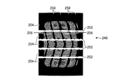
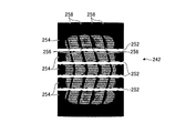
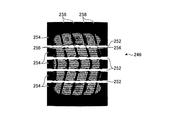
Next, an evaluation example in which the simulation method of this embodiment is executed will be described with reference to FIGS. 11A to 11D and FIG. Here, FIG. 11A to FIG. 11D are explanatory diagrams illustrating examples of analysis results of the tire simulation method according to the present embodiment, respectively. FIG. 12 is an explanatory diagram illustrating an example of an analysis result of the tire simulation method according to the present embodiment. The tire simulation method according to FIGS. 3 to 5 was executed using a tire model having a size of 215 / 55R17 and an air pressure of 230 kPa and an analysis model of a road surface model. As shown in FIGS. 11A to 11D, in the tire model, as shown in the analysis results 242, 244, 246, and 248, a
また、本評価例では、基準とする接地位置、基準からタイヤモデルと路面モデルとの相対位置をタイヤ周方向に1/4ピッチ分ずらした接地位置、基準からタイヤモデルと路面モデルとの相対位置をタイヤ周方向に2/4(1/2)ピッチ分ずらした接地位置、基準からタイヤモデルと路面モデルとの相対位置をタイヤ周方向に3/4ピッチ分ずらした接地位置の4つの場合について剛性を解析した。なお、ピッチとは、タイヤトレッド部に形成されるブロックの繰り返し単位の1つ分の長さである。解析結果を図11Aから図11Dに示す。なお、図11Aには、基準位置の解析結果242、図11Bは、1/4ピッチずらした位置の解析結果244、図11Cは、1/2ピッチずらした位置の解析結果246、図11Dには、3/4ピッチずらした位置の解析結果248を示す。また、図11Aから図11Dに示す解析結果242、244、246、248では、各部で検出された剛性を色によって示している。
Further, in this evaluation example, the contact position as a reference, the contact position obtained by shifting the relative position between the tire model and the road surface model from the reference by ¼ pitch in the tire circumferential direction, and the relative position between the tire model and the road surface model from the reference. Is the ground contact position shifted by 2/4 (1/2) pitch in the tire circumferential direction, and the ground contact position where the relative position between the tire model and the road surface model is shifted by 3/4 pitch in the tire circumferential direction from the reference. The stiffness was analyzed. In addition, a pitch is the length for one repeating unit of the block formed in a tire tread part. The analysis results are shown in FIGS. 11A to 11D. 11A shows the
図11Aから図11Dに示すように、本実施形態のシミュレーション方法によれば、路面モデルとタイヤモデルとの接触位置によって、検査される剛性が異なることがわかる。
具体的には、図11Aに示す解析結果242から算出されたブロック部の剛性は1313.5N/mmであり、図11Bに示す解析結果244から算出されたブロック部の剛性は1328.7N/mmであり、図11Cに示す解析結果246から算出されたブロック部の剛性は1334.7N/mmであり、図11Dに示す解析結果248から算出されたブロック部の剛性は1320.4N/mmである。また、4つの解析結果242、244、246、248から算出されたブロック部の剛性の平均値は、1324.3N/mmである。以上より、タイヤモデルの変形計算(接地解析)を行い、タイヤモデルを変形させ、その形状に基づいて剛性を解析することで、より正確な剛性を算出できることがわかる。
As shown in FIGS. 11A to 11D, according to the simulation method of the present embodiment, it can be seen that the inspected rigidity differs depending on the contact position between the road surface model and the tire model.
Specifically, the rigidity of the block portion calculated from the
また、解析した結果に基づいて、タイヤ周方向の接触せん断応力の分布を算出した結果を図12に示す。図12の解析結果280に示すように、本実施形態のシミュレーション方法を用いることで、タイヤ周方向の接触せん断応力の分布も好適に算出することができる。
Moreover, the result of having calculated the distribution of the contact shear stress of the tire circumferential direction based on the analyzed result is shown in FIG. As shown in the
1 タイヤ
50 解析装置
51 入出力装置
52 処理部
52a モデル作成部
52b モデル領域設定部
52c 第1解析部
52d 剛体設定部
52e 第2解析部
54 記憶部
60 解析モデル
62 タイヤモデル
64 路面モデル
72 タイヤトレッド部
74 タイヤサイド部
76、78 領域
82 第1領域
84 第2領域
DESCRIPTION OF SYMBOLS 1
Claims (8)
前記コンピュータが、前記解析モデルを、剛性を評価する第1領域と、前記第1領域以外の第2領域との境界を設定する分割ステップと、
前記コンピュータが、前記解析モデルの変形計算を行う変形計算ステップと、
前記コンピュータが、前記変形計算ステップの結果に基づいて変形させた前記解析モデルの、少なくとも前記第1領域と前記第2領域との境界を含み、かつ、前記第1領域を含まない領域を実質的に剛体とする剛性設定ステップと、
前記コンピュータが、剛体設定ステップで変換した前記解析モデルを解析し第1領域の剛性を算出する解析ステップと、を含むことを特徴とするタイヤのシミュレーション方法。 A model creation step in which a computer creates an analysis model including at least a tire model of the tire based on a tire to be analyzed;
A division step in which the computer sets a boundary between a first region for evaluating rigidity and a second region other than the first region in the analysis model;
A deformation calculation step in which the computer calculates a deformation of the analysis model; and
The analysis model deformed on the basis of the result of the deformation calculation step by the computer substantially includes an area including at least a boundary between the first area and the second area and not including the first area. A rigidity setting step for making the body into a rigid body,
An analysis step in which the computer analyzes the analysis model converted in the rigid body setting step and calculates the rigidity of the first region.
前記変位反力算出ステップで算出した結果から第1領域の剛性を算出する剛性算出ステップと、を有することを特徴とする請求項1に記載のタイヤのシミュレーション方法。 The analysis step performs a displacement reaction force calculation step of performing an analysis with an input of forced displacement applied to the analysis model converted in the rigid body setting step, and detecting a reaction force and a displacement;
2. The tire simulation method according to claim 1, further comprising: a stiffness calculation step of calculating a stiffness of the first region from a result calculated in the displacement reaction force calculation step.
物理量の分布から、接地域内の複数の部分の寄与を算出するステップを有することを特徴とする請求項4から6のいずれか一項に記載のタイヤのシミュレーション方法。 The analysis step includes obtaining a physical quantity distribution in the contact tangential direction of the contact area based on the calculated stiffness of the first area;
The tire simulation method according to any one of claims 4 to 6, further comprising a step of calculating contributions of a plurality of portions in the contact area from the physical quantity distribution.
Priority Applications (1)
| Application Number | Priority Date | Filing Date | Title |
|---|---|---|---|
| JP2011008111A JP2012148653A (en) | 2011-01-18 | 2011-01-18 | Simulation method of tire and computer program for simulation of tire |
Applications Claiming Priority (1)
| Application Number | Priority Date | Filing Date | Title |
|---|---|---|---|
| JP2011008111A JP2012148653A (en) | 2011-01-18 | 2011-01-18 | Simulation method of tire and computer program for simulation of tire |
Publications (1)
| Publication Number | Publication Date |
|---|---|
| JP2012148653A true JP2012148653A (en) | 2012-08-09 |
Family
ID=46791372
Family Applications (1)
| Application Number | Title | Priority Date | Filing Date |
|---|---|---|---|
| JP2011008111A Pending JP2012148653A (en) | 2011-01-18 | 2011-01-18 | Simulation method of tire and computer program for simulation of tire |
Country Status (1)
| Country | Link |
|---|---|
| JP (1) | JP2012148653A (en) |
Cited By (2)
| Publication number | Priority date | Publication date | Assignee | Title |
|---|---|---|---|---|
| JP2014097730A (en) * | 2012-11-14 | 2014-05-29 | Sumitomo Rubber Ind Ltd | Tire simulation method and simulation device |
| JP2014160321A (en) * | 2013-02-19 | 2014-09-04 | Msc Software Corp | Structure analysis device |
-
2011
- 2011-01-18 JP JP2011008111A patent/JP2012148653A/en active Pending
Cited By (2)
| Publication number | Priority date | Publication date | Assignee | Title |
|---|---|---|---|---|
| JP2014097730A (en) * | 2012-11-14 | 2014-05-29 | Sumitomo Rubber Ind Ltd | Tire simulation method and simulation device |
| JP2014160321A (en) * | 2013-02-19 | 2014-09-04 | Msc Software Corp | Structure analysis device |
Similar Documents
| Publication | Publication Date | Title |
|---|---|---|
| US8200463B2 (en) | Method of simulating rolling tire | |
| JP5829861B2 (en) | Prediction method for tire wear energy and tire design method | |
| JP5672797B2 (en) | Simulation model creation method, simulation method, simulation model creation device, and simulation device | |
| JP4635668B2 (en) | Tire performance prediction method, tire performance prediction computer program, and tire / wheel assembly model creation method | |
| JP4639912B2 (en) | Tire performance prediction method, tire performance prediction computer program, and tire / wheel assembly model creation method | |
| JP3431818B2 (en) | Simulation method of tire performance | |
| JP2004142571A (en) | Prediction method and device of physical quantity for tire wear, and computer program | |
| JP5585436B2 (en) | Tire simulation method | |
| JPH11153520A (en) | Method and apparatus for simulation of performance of tire | |
| JP4067934B2 (en) | Tire performance prediction method using tire model, tire performance prediction program, and input / output device | |
| JP5104042B2 (en) | Tire performance prediction method, tire performance prediction computer program, and tire design method | |
| JP2012148653A (en) | Simulation method of tire and computer program for simulation of tire | |
| JP5786289B2 (en) | Tire simulation method and tire simulation computer program | |
| JP4318971B2 (en) | Tire performance simulation method and tire design method | |
| JP3314082B2 (en) | How to create a tire finite element model | |
| JP5541045B2 (en) | Tire analysis method, tire analysis computer program, and analysis apparatus | |
| JP2001282873A (en) | Finite element method analyis model, tire model generation method, tire performance simulation method and device thereof | |
| JP5782684B2 (en) | Simulation model creation method, simulation method, simulation model creation device, and simulation device | |
| JP5811625B2 (en) | Simulation method and simulation apparatus | |
| JP5584004B2 (en) | Tire performance prediction method and tire performance prediction apparatus | |
| JP3363442B2 (en) | Simulation method of tire performance | |
| JP4116337B2 (en) | Tire performance simulation method and apparatus | |
| JP2012181600A (en) | Tire model creation method, tire model creation device, tire model creation program, and tire performance analysis method | |
| JP6163749B2 (en) | Tire simulation method, tire characteristic evaluation method, tire manufacturing method | |
| JP5678502B2 (en) | Tire model creation method, tire model creation computer program, tire simulation method, and tire model creation apparatus |