EP1473474B2 - A hub unit for an automobile - Google Patents
A hub unit for an automobile Download PDFInfo
- Publication number
- EP1473474B2 EP1473474B2 EP04015614A EP04015614A EP1473474B2 EP 1473474 B2 EP1473474 B2 EP 1473474B2 EP 04015614 A EP04015614 A EP 04015614A EP 04015614 A EP04015614 A EP 04015614A EP 1473474 B2 EP1473474 B2 EP 1473474B2
- Authority
- EP
- European Patent Office
- Prior art keywords
- taper
- rollers
- peripheral surface
- inner ring
- outer ring
- Prior art date
- Legal status (The legal status is an assumption and is not a legal conclusion. Google has not performed a legal analysis and makes no representation as to the accuracy of the status listed.)
- Expired - Lifetime
Links
Images


Classifications
-
- F—MECHANICAL ENGINEERING; LIGHTING; HEATING; WEAPONS; BLASTING
- F16—ENGINEERING ELEMENTS AND UNITS; GENERAL MEASURES FOR PRODUCING AND MAINTAINING EFFECTIVE FUNCTIONING OF MACHINES OR INSTALLATIONS; THERMAL INSULATION IN GENERAL
- F16C—SHAFTS; FLEXIBLE SHAFTS; ELEMENTS OR CRANKSHAFT MECHANISMS; ROTARY BODIES OTHER THAN GEARING ELEMENTS; BEARINGS
- F16C43/00—Assembling bearings
- F16C43/04—Assembling rolling-contact bearings
-
- F—MECHANICAL ENGINEERING; LIGHTING; HEATING; WEAPONS; BLASTING
- F16—ENGINEERING ELEMENTS AND UNITS; GENERAL MEASURES FOR PRODUCING AND MAINTAINING EFFECTIVE FUNCTIONING OF MACHINES OR INSTALLATIONS; THERMAL INSULATION IN GENERAL
- F16C—SHAFTS; FLEXIBLE SHAFTS; ELEMENTS OR CRANKSHAFT MECHANISMS; ROTARY BODIES OTHER THAN GEARING ELEMENTS; BEARINGS
- F16C19/00—Bearings with rolling contact, for exclusively rotary movement
- F16C19/22—Bearings with rolling contact, for exclusively rotary movement with bearing rollers essentially of the same size in one or more circular rows, e.g. needle bearings
- F16C19/34—Bearings with rolling contact, for exclusively rotary movement with bearing rollers essentially of the same size in one or more circular rows, e.g. needle bearings for both radial and axial load
- F16C19/38—Bearings with rolling contact, for exclusively rotary movement with bearing rollers essentially of the same size in one or more circular rows, e.g. needle bearings for both radial and axial load with two or more rows of rollers
- F16C19/383—Bearings with rolling contact, for exclusively rotary movement with bearing rollers essentially of the same size in one or more circular rows, e.g. needle bearings for both radial and axial load with two or more rows of rollers with tapered rollers, i.e. rollers having essentially the shape of a truncated cone
- F16C19/385—Bearings with rolling contact, for exclusively rotary movement with bearing rollers essentially of the same size in one or more circular rows, e.g. needle bearings for both radial and axial load with two or more rows of rollers with tapered rollers, i.e. rollers having essentially the shape of a truncated cone with two rows, i.e. double-row tapered roller bearings
- F16C19/386—Bearings with rolling contact, for exclusively rotary movement with bearing rollers essentially of the same size in one or more circular rows, e.g. needle bearings for both radial and axial load with two or more rows of rollers with tapered rollers, i.e. rollers having essentially the shape of a truncated cone with two rows, i.e. double-row tapered roller bearings in O-arrangement
-
- F—MECHANICAL ENGINEERING; LIGHTING; HEATING; WEAPONS; BLASTING
- F16—ENGINEERING ELEMENTS AND UNITS; GENERAL MEASURES FOR PRODUCING AND MAINTAINING EFFECTIVE FUNCTIONING OF MACHINES OR INSTALLATIONS; THERMAL INSULATION IN GENERAL
- F16C—SHAFTS; FLEXIBLE SHAFTS; ELEMENTS OR CRANKSHAFT MECHANISMS; ROTARY BODIES OTHER THAN GEARING ELEMENTS; BEARINGS
- F16C33/00—Parts of bearings; Special methods for making bearings or parts thereof
- F16C33/30—Parts of ball or roller bearings
- F16C33/46—Cages for rollers or needles
- F16C33/4617—Massive or moulded cages having cage pockets surrounding the rollers, e.g. machined window cages
- F16C33/4623—Massive or moulded cages having cage pockets surrounding the rollers, e.g. machined window cages formed as one-piece cages, i.e. monoblock cages
- F16C33/4635—Massive or moulded cages having cage pockets surrounding the rollers, e.g. machined window cages formed as one-piece cages, i.e. monoblock cages made from plastic, e.g. injection moulded window cages
-
- F—MECHANICAL ENGINEERING; LIGHTING; HEATING; WEAPONS; BLASTING
- F16—ENGINEERING ELEMENTS AND UNITS; GENERAL MEASURES FOR PRODUCING AND MAINTAINING EFFECTIVE FUNCTIONING OF MACHINES OR INSTALLATIONS; THERMAL INSULATION IN GENERAL
- F16C—SHAFTS; FLEXIBLE SHAFTS; ELEMENTS OR CRANKSHAFT MECHANISMS; ROTARY BODIES OTHER THAN GEARING ELEMENTS; BEARINGS
- F16C2326/00—Articles relating to transporting
- F16C2326/01—Parts of vehicles in general
- F16C2326/02—Wheel hubs or castors
-
- Y—GENERAL TAGGING OF NEW TECHNOLOGICAL DEVELOPMENTS; GENERAL TAGGING OF CROSS-SECTIONAL TECHNOLOGIES SPANNING OVER SEVERAL SECTIONS OF THE IPC; TECHNICAL SUBJECTS COVERED BY FORMER USPC CROSS-REFERENCE ART COLLECTIONS [XRACs] AND DIGESTS
- Y10—TECHNICAL SUBJECTS COVERED BY FORMER USPC
- Y10S—TECHNICAL SUBJECTS COVERED BY FORMER USPC CROSS-REFERENCE ART COLLECTIONS [XRACs] AND DIGESTS
- Y10S33/00—Geometrical instruments
- Y10S33/17—Piston ring and bearing race gauging
-
- Y—GENERAL TAGGING OF NEW TECHNOLOGICAL DEVELOPMENTS; GENERAL TAGGING OF CROSS-SECTIONAL TECHNOLOGIES SPANNING OVER SEVERAL SECTIONS OF THE IPC; TECHNICAL SUBJECTS COVERED BY FORMER USPC CROSS-REFERENCE ART COLLECTIONS [XRACs] AND DIGESTS
- Y10—TECHNICAL SUBJECTS COVERED BY FORMER USPC
- Y10T—TECHNICAL SUBJECTS COVERED BY FORMER US CLASSIFICATION
- Y10T29/00—Metal working
- Y10T29/49—Method of mechanical manufacture
- Y10T29/49481—Wheel making
- Y10T29/49492—Land wheel
- Y10T29/49533—Hub making
- Y10T29/49535—Hub making with assembling
-
- Y—GENERAL TAGGING OF NEW TECHNOLOGICAL DEVELOPMENTS; GENERAL TAGGING OF CROSS-SECTIONAL TECHNOLOGIES SPANNING OVER SEVERAL SECTIONS OF THE IPC; TECHNICAL SUBJECTS COVERED BY FORMER USPC CROSS-REFERENCE ART COLLECTIONS [XRACs] AND DIGESTS
- Y10—TECHNICAL SUBJECTS COVERED BY FORMER USPC
- Y10T—TECHNICAL SUBJECTS COVERED BY FORMER US CLASSIFICATION
- Y10T29/00—Metal working
- Y10T29/49—Method of mechanical manufacture
- Y10T29/49636—Process for making bearing or component thereof
- Y10T29/49643—Rotary bearing
- Y10T29/49679—Anti-friction bearing or component thereof
- Y10T29/49682—Assembling of race and rolling anti-friction members
-
- Y—GENERAL TAGGING OF NEW TECHNOLOGICAL DEVELOPMENTS; GENERAL TAGGING OF CROSS-SECTIONAL TECHNOLOGIES SPANNING OVER SEVERAL SECTIONS OF THE IPC; TECHNICAL SUBJECTS COVERED BY FORMER USPC CROSS-REFERENCE ART COLLECTIONS [XRACs] AND DIGESTS
- Y10—TECHNICAL SUBJECTS COVERED BY FORMER USPC
- Y10T—TECHNICAL SUBJECTS COVERED BY FORMER US CLASSIFICATION
- Y10T29/00—Metal working
- Y10T29/49—Method of mechanical manufacture
- Y10T29/49636—Process for making bearing or component thereof
- Y10T29/49696—Mounting
-
- Y—GENERAL TAGGING OF NEW TECHNOLOGICAL DEVELOPMENTS; GENERAL TAGGING OF CROSS-SECTIONAL TECHNOLOGIES SPANNING OVER SEVERAL SECTIONS OF THE IPC; TECHNICAL SUBJECTS COVERED BY FORMER USPC CROSS-REFERENCE ART COLLECTIONS [XRACs] AND DIGESTS
- Y10—TECHNICAL SUBJECTS COVERED BY FORMER USPC
- Y10T—TECHNICAL SUBJECTS COVERED BY FORMER US CLASSIFICATION
- Y10T29/00—Metal working
- Y10T29/49—Method of mechanical manufacture
- Y10T29/49636—Process for making bearing or component thereof
- Y10T29/497—Pre-usage process, e.g., preloading, aligning
-
- Y—GENERAL TAGGING OF NEW TECHNOLOGICAL DEVELOPMENTS; GENERAL TAGGING OF CROSS-SECTIONAL TECHNOLOGIES SPANNING OVER SEVERAL SECTIONS OF THE IPC; TECHNICAL SUBJECTS COVERED BY FORMER USPC CROSS-REFERENCE ART COLLECTIONS [XRACs] AND DIGESTS
- Y10—TECHNICAL SUBJECTS COVERED BY FORMER USPC
- Y10T—TECHNICAL SUBJECTS COVERED BY FORMER US CLASSIFICATION
- Y10T29/00—Metal working
- Y10T29/49—Method of mechanical manufacture
- Y10T29/49764—Method of mechanical manufacture with testing or indicating
- Y10T29/49771—Quantitative measuring or gauging
-
- Y—GENERAL TAGGING OF NEW TECHNOLOGICAL DEVELOPMENTS; GENERAL TAGGING OF CROSS-SECTIONAL TECHNOLOGIES SPANNING OVER SEVERAL SECTIONS OF THE IPC; TECHNICAL SUBJECTS COVERED BY FORMER USPC CROSS-REFERENCE ART COLLECTIONS [XRACs] AND DIGESTS
- Y10—TECHNICAL SUBJECTS COVERED BY FORMER USPC
- Y10T—TECHNICAL SUBJECTS COVERED BY FORMER US CLASSIFICATION
- Y10T29/00—Metal working
- Y10T29/49—Method of mechanical manufacture
- Y10T29/4981—Utilizing transitory attached element or associated separate material
Definitions
- the present invention relates to a method of assembling a hub unit for an automobile.
- a negative axial (axial direction) gap In a conventional double row taper-roller bearing, the control of a negative axial (axial direction) gap has hitherto involved such a construction that two pieces of inner rings are disposed side by side on a cylindrical member facing to one single outer ring having two tapered track surfaces, and a spacer is interposed between two inner rings. More specifically, so to speak, two sets of completed taper-roller bearings are disposed side by side in the axial direction, the spacer is interposed therebetween, a pre-load is controlled by fastening the two bearings from the axial direction, and the double row taper-roller bearing is assembled.
- the double row taper-roller bearing tends to be a part of an apparatus using this type of bearing rather than a single unit of bearing, wherein an inner ring and an outer ring of the bearing are being made integral with the members which have supported so far the inner ring and the outer ring.
- the conventional inner ring and outer ring be united into one unit integral with a flanged member formed with a bolt hole, which has hitherto supported the inner ring and the outer ring and fixedly joined to the wheel or the car body.
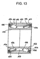
- FIG.13 shows a double rowtaper-roller bearing 100 which has been broadly used so far for supporting the wheel.
- This double row taper-roller bearing 100 is constructed in such a way that a pair of inner rings 103, 103 are each so supported by a plurality of taper-rollers 104, 104 as to be rotatable on a minor-diameter side of one single outer ring 102.
- Double row outer ring tracks 105, 105 each taking a configuration of tapered concave surface are formed along an inner peripheral surface of the outer ring 102
- inner ring tracks 106, 106 each assuming a configuration of tapered convex surface are formed along outer peripheral surfaces of the respective inner rings 103,103.
- the taper-rollers 104, 104 are sandwiched in between the outer ring tracks 105, 105 and the inner ring tracks 106, 106 in a state the rollers 104, 104 are so held by cages or holders 107,107 as to be reliable. Further, combined seal rings 108, 108 are attached between an inner peripheral surface at two side ends of the outer ring 102 and outer peripheral surfaces of side ends of the inner rings 103, 103, thereby closing openings at two axial side ends of an air space 109 in which the taper-rollers 104, 104 are set.
- the above-described double row taper-roller bearing 100 which has hitherto been widely used, is assembled in procedures shown in FIGS. 14 and 15 .
- the taper-rollers 104, 104 are arranged along circumferences of the inner rings 103, 103 in the state of being so held by the cages or holders 107, 107 as to be reliable.
- the inner rings 103, 103 are inserted inside of the outer ring 102 while remaining in this state, and, as shown in FIG. 15 , the taper-rollers 104, 104 are brought into contact with the outer ring tracks 105, 105 and the inner ring tracks 106, 106.
- the combined seal rings 108, 108 are attached between the outer peripheral surfaces of the side ends of the inner rings 103, 103 and the inner peripheral surface at the two side ends of the outer ring 102.
- the double row taper-roller bearing 100 itself which is shown in FIG. 13 , has no particular problem.
- a so-called third-generation hub unit structure has been contrived, wherein the double row taper-roller bearing for supporting the wheel is provided integrally with the hub for supporting and fixing the wheel.
- a flange for supporting the wheel is provided on an outer peripheral surface of one side end of the hub body, and a first inner ring track taking a configuration of tapered convex surface and serving to configure the taper-roller bearing of the first row, is formed directly along an outer peripheral surface of an intermediate portion.
- an inner ring having a second inner ring track taking a configuration of tapered convex surface, for configuring the taper-roller bearing of the second row, is fixedly fitted to an outer portion of small-diameter stepped portion formed on an outer peripheral surface of the other side end of the hub body.
- FIG.1 is an explanatory view showing a method of controlling an axial gap when assembling a taper-roller bearing of a hub unit for fitting a driving front wheel of an automobile.
- a hub 1 of the hub unit integrally includes, as the integral parts, a flange 11 for fixing a rim (not shown) of the front wheel, and a cylindrical member 12 extending in an axial direction, to be formed with the taper-roller bearing along an outer periphery thereof and to fix along an inner periphery thereof an axle (unillustrated).
- the flange 11 is formed with a proper number of bolt holes 13, and the rim of the wheel (not shown) is fixed by bolts 14.
- the axle is, as described above, inserted into a central hole 15 of the cylindrical member 12 extending in the axial direction, and the hub 11 is fixed to the axle by bolts (unillustrated) in a bolt hole 16 formed in the central portion of the hub 11.
- the hub and the wheel i.e., the wheel and the axle integrally rotate.
- the cylindrical member 12 serving as a first inner ring member extends in the axial direction, of which an outer periphery is formed with a first track surface 17 configuring a part of a tapered shape opened toward the flange.
- the cylindrical member 12 has a large collar portion 18 extending from a side end on a large-diameter-side of the first track surface 17.
- An outer ring 20 is disposed outside in the radial direction of the cylindrical member 12.
- the outer ring 20 is formed with a first inside track surface 21 constituting a part of the tapered shape, facing to the first track surface 17 formed along the cylindrical member 12 serving as a first inner ring member.
- a predetermined number of first taper-rollers 40 held by a first cage or holder 30 are interposed between the first track surface 17 of the first inner ring member defined as the cylindrical member 12 and the first inside track surface 21 of the outer ring 20.
- the first holder 30 and the first taper-rollers 40 are combined to constitute a first roller row.
- the outer ring 20 is formed with a second inside track surface 22 configuring a part of the tapered shape opened opposite to the first inside track surface 21, and spaced at a predetermined axial distance away from the first inside track surface described above.
- a first inner ring member constructed of the cylindrical member 12 has a small-diameter cylindrical portion 12a, formed at a portion facing in the axial direction to the second inside track surface 22 of the outer ring 20, of which an outer periphery is formed with a cylindrical surface with a substantially uniform diameter.
- a second inner ring member 12b is fixedly fitted to this small-diameter cylindrical portion 12a.
- An outer periphery of the second inner ring member 12b is formed with a second track surface 12c constituting a part of the tapered shape, facing to the second inside track surface 22 of the outer ring 20.
- a predetermined number of second taper-rollers 50 held by a second cage or holder 51 are interposed between the second inside track surface 22 of the outer ring 20 and the second track surface 12c of the second inner ring member 12b in such a way that the rollers 50 roll while being kept in contact with these track surfaces.
- the second taper-rollers 50 and the second holder 51 are combined to constitute a second roller row.
- the outer ring 20 has a flange 25 substantially at the center of the outer periphery thereof.
- the flange 25 is formed with a hole 26 through which a bolt (not shown) is inserted to fix the outer ring to a knuckle of a suspension system on the car body side.
- the hub unit is formed with the double row taper-roller bearing.
- the first roller row composed of the first taper-rollers 40 held by the first holder 30, is fitted onto the first track surface 17 of the first inner ring member 12, and then the outer ring 20 is fitted to the outer portion thereof.
- the second roller row composed of the second taper-rollers 50 held by the second holder 51 is so fitted as to come into contact with the second inside track surface 22 of the outer ring 20.
- a master member of the second inner ring member which has the known dimensions and a positive axial gap with respect to the assembled taper-roller bearing, is inserted into a space formed between the second roller row and the small-diameter cylindrical portion 12a.
- a tentative axial gap is measured, and, as a next step, dimensions of the second inner ring member for obtaining a negative axial gap on a desired specification are arithmetically obtained based on a measured result of the tentative axial gap.
- a second inner ring member 12b having proper dimensions is chosen out of a stocker of the second inner ring members, corresponding to this arithmetic result, and the second inner ring member selected as a substitute for the master member is incorporated, thereby obtaining the double row taper-roller bearing based on the desired specification.
- the second inner ring member 12b may be selected and incorporated either by a manual work or by an automatic operation.
- the negative axial gap of the double row taper-roller bearing which cannot be ensured after the assembly, can be controlled by use of the master member before the assembly.
- FIGS. 3-8 Illustrate an embodiment of the hub unit for the automobile accordingtothe present invention.
- the hub unit 10 for the automobile is constructed of a hub body 11 a, an Inner ring member 12 externally fitted to the hub body 11 a, an outer ring 20 disposed along the peripheries of the hub body 11 a and of the inner ring member 12b, a plurality of taper-rollers 40, 50 provided between outer peripheral surfaces of the hub body 11 a and of the inner ring member 12b and an inner peripheral surface of the outer ring 20, a first seal ring 15a for hermetically sealing between an inner peripheral surface of one side end of the outer ring 20 and an outer peripheral surface of an intermediate portion of the hub body 11a, and a second seal ring 15b for hermetically sealing between an inner peripheral surface of the other side end of the outer ring 20 and an outer peripheral surface of a side end ofthe inner ring member 12b.
- a single seal ring is used as the first seal ring 15a, and a combined seal ring
- the hub body 11 a among those components has a flange 11 for supporting the wheel on an outer peripheral surface of one side end (an outer side end in the widthwise direction in a state of being assembled to the car body, corresponding to a left side end in FIG. 1 ). Further, a first inner ring track 17, taking a configuration of tapered convex surface, for configuring the taper-roller bearing 18a of the first row, is formed directly on the outer peripheral surface of the intermediate portion of the hub body 11 a. Furthermore, a small-diameter stepped portion 12a is provided on the outer peripheral surface of the other side end (an inner side end in the widthwise direction in the state of being assembled to the car body, corresponding to a right side end in FIG.
- An outer peripheral surface of the small-diameter stepped portion 12a takes a cylindrical shape concentric with the hub body 11 a.
- the automobile hub unit 10 for supporting the driving wheel is provided, and hence a spline hole 21 a for spline-engaging with a side end of a drive axle is provided in a central portion of the hub body 11 a.
- the inner ring member 12b includes a second inner ring track 12c assuming a configuration of tapered convex surface and formed along the outer peripheral surface, for configuring the taper-roller bearing 22a of the second row, and fixedly fitted to an outer portion of the small-diameter stepped portion 12a of the hub body 11a.
- An inclined direction of the second inner ring track 12c is set opposite to an inclined direction of the first inner ring track 17.
- a proximal end (a right side end in FIG. 3 ) of the inner ring member 12b protrude slightly from the other side end surface (a right side end surface in FIG. 3 ) of the hub body 11 a in a state of letting a front side end surface (a left side end surface in FIG.
- the inner peripheral surface of the outer ring 20 is formed with first and second outer ring tracks 21, 22, each taking a configuration of tapered concave surface, for configuring the taper-roller bearings 18a, 22a of the first and second rows. Inclined directions of the first and second outer ring tracks 21, 22 are set opposite to each other, corresponding to the first and second inner ring tracks 17, 12c. Further, the axially intermediate portion of the outer peripheral surface of the outer ring 20 is provided with an outward-flange-like fitting portion 25 for fixing the outer ring 20 to an unillustrated suspension.
- taper-rollers 40, 40 (a left half in FIG. 3 ) among the plurality of taper-rollers 40, 50 are disposed between the first inner ring track 17 and the first outer ring track 21 in a state of being so held by the first holder as to be reliable.
- the remaining taper-rollers 50, 50 (a right half in FIG. 1 ) among the plurality of taper-rollers 40, 50 are disposed between the second inner ring track 12c and the second outer ring track 22 in a state being so held by the second holder 51 as to be reliable.
- the first holder 30 in a state of holding some taper-rollers 40, 40 among the plurality of taper-rollers 40, 50, prevents the respective taper-rollers 40, 40 from coming off inward in the diametrical direction. Therefore, in the embodiment illustrated, what takes a configuration as shown in FIGS. 5 and 6 is used as the first holder 30.
- the first holder 30 is formed in a partially tapered cylindrical shape on the whole by injection-molding a synthetic resin exhibiting elasticity, and has pockets 30b, 30b and columns 31, 31 which are provided alternately in the circumferential direction.
- the taper-rollers 40, 40 are so disposed in the pockets 30b, 30b as to be reliable.
- each of the columns 31, 31 is positioned more outwards in the diametrical direction than a pitch circle a of each of the taper-rollers 40, 40, and similarly an innerperipheral surface thereof is positioned more inwards than the pitch circle a. Then, widths, extending in the circumferential direction, of two major- and minor-diameter-side openings of the pockets 30b, 30b are set well smaller than a diameter of each of the taper-rollers 40, 40 on the major diameter side, and set slightly smaller than this diameter on the minor diameter side.
- an operation of setting the taper-rollers 40, 40 into the pockets 30b, 30b is performed while elastically deforming the columns 31, 31 in the circumferential direction from the minor-diameter side of the first holder 30.
- the columns 31, 31 adjacent to each other in the circumferential direction are, when the pockets accommodate the rollers, elastically deformed in such directions as to get apart from each other in the circumferential direction, and permit the taper-rollers 40, 40 to pass through.
- a spacing (corresponding to a circumference-directional width W 30 of each of the two minor-diameter-side openings of the pockets 30b, 30b) between the columns 31, 31 adjacent to each other in the circumferential direction, is smaller than a major diameter D 14 of each of the taper-rollers 40, 40.
- the first holder 30 prevents the taper-rollers 40, 40 from unexpectedly coming off inwards in the diametrical direction.
- the width W 30 and the major diameter D 14 gradually change in the axial direction of each of the taper-rollers 40, 40, however, the dimensional relationship described above is met in positions aligned with each other.
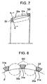
- the second holder 51 assumes a configuration as shown in FIGS. 7 and 8 , and, in the state of holding in a reliable manner the remaining taper-rollers 50, 50 among the plurality of taper-rollers 40, 50, prevents these taper-rollers 50, 50 from coming off outwards in the diametrical direction.
- the second holder51 itself is the same as the holder 107 incorporated into the proposed structure shown in FIGS. 13 - 15 .
- the second holder 51 is formed in a partially tapered cylindrical shape on the whole by injection-molding a synthetic resin, and has pockets 30a, 30a and columns 31 a, 31 a which are provided alternately in the circumferential direction.
- Both of the outer and inner peripheral surfaces of the columns 31 a, 31 a are positioned more outwards in the diametrical direction than a pitch circle ⁇ of each of the taper-rollers 50, 50. Then, widths, extending in the circumferential direction, of two major-diameter-side openings of the pockets 30a, 30a are set well smaller than a diameter of each of the taper-rollers 50, 50, and set larger than this diameter on the minor diameter side. Accordingly, an operation of setting the taper-rollers 50, 50 into the pockets 30a, 30a is carried out from the minor-diameter side ofthe second holder 51.
- the taper-rollers 50, 50 are set into the pockets 30a, 30a, and the inner ring 12b is inserted on the minor-diameter side of each of the taper-rollers 50, 50, in which state these taper-rollers 50, 50 are so held in the pockets 30a, 30a that these taper-rollers cannot come off.
- FIGS. 9 - 12 the method of assembling the automobile hub unit 10 having the construction described above will be explained with reference to FIGS. 9 - 12 in addition to FIGS. 3 - 8 .
- some taper-rollers 40, 40 among the plurality of taper-rollers 40, 50 are held by the first holder 30.
- these taper-rollers 40, 40 are held by the first holder 30 without being separated. It is therefore feasible to easily carry it in the factory.
- the taper-rollers 40, 40 in this state are, as illustrated in FIG. 10 , disposed inside the first outer ring track 21 on the inner peripheral surface of the outer ring 20.
- the first seal ring 15a is fixedly fitted to the inner peripheral surface of one side end of the outer ring 20. In this state, the taper-rollers 40, 40 and the first holder 30 are combined without being separated.
- some taper-rollers 40, 40 are disposed on the inner-diameter side of the outer ring 20, and the first seal ring 15a is fixedly fitted inside, in which state as shown in FIGS. 10 and 11 the hub body 11 a is inserted inside the outer ring 20.
- This inserting operation continues till there is attained a state where the first inner ring track 17 is positioned inwardly of some taper-rollers 40, 40 among the plurality of taper-rollers 40, 50, and the first seal ring 15a comes into contact with an entire periphery of an area, between the flange 11 and the first inner ring track 17, of the surface of the outer ring 20.
- the inner ring member 12b is inserted inside the outer ring 20 in a state where the remaining taper-rollers 50, 50 among the plurality of taper-rollers 40, 50 are held among the circumference of the second inner ring track 12c by the second holder 51. Then, with this inserting operation, the inner ring member 12b is fixedly fitted to the outer portion ofthe small-diameter stepped portion 12a of the hub body 11 a. Then, finally, as illustrated in FIGS. 12 and 3 , the second seal ring 15b is attached between the outer peripheral surface of the side end of the inner ring member 12b and the inner peripheral surface of the side end of the outer ring 20. Note that a pre-load applied to each of the taper-roller bearings 18a of the first and second rows may be arbitrarily readily adjusted by changing a grinding quantity of a part of the inner ring 12b.
- the costs for the automobile hub unit can be reduced by assembling the novel third-generation automobile hub unit at a high efficiency.
Landscapes
- Engineering & Computer Science (AREA)
- General Engineering & Computer Science (AREA)
- Mechanical Engineering (AREA)
- Rolling Contact Bearings (AREA)
- Automobile Manufacture Line, Endless Track Vehicle, Trailer (AREA)
Description
- The present invention relates to a method of assembling a hub unit for an automobile.
- In a conventional double row taper-roller bearing, the control of a negative axial (axial direction) gap has hitherto involved such a construction that two pieces of inner rings are disposed side by side on a cylindrical member facing to one single outer ring having two tapered track surfaces, and a spacer is interposed between two inner rings. More specifically, so to speak, two sets of completed taper-roller bearings are disposed side by side in the axial direction, the spacer is interposed therebetween, a pre-load is controlled by fastening the two bearings from the axial direction, and the double row taper-roller bearing is assembled.
- The double row taper-roller bearing, however, tends to be a part of an apparatus using this type of bearing rather than a single unit of bearing, wherein an inner ring and an outer ring of the bearing are being made integral with the members which have supported so far the inner ring and the outer ring. For example, in the double row taper-roller bearing for the hub unit for fitting a wheel of an automobile, it has been proposed that the conventional inner ring and outer ring be united into one unit integral with a flanged member formed with a bolt hole, which has hitherto supported the inner ring and the outer ring and fixedly joined to the wheel or the car body.
- What is proposed above is, however, unable to control in fact the negative axial gap and can be therefore neither assembled nor used.
-
FIG.13 shows a double rowtaper-roller bearing 100 which has been broadly used so far for supporting the wheel. This double row taper-roller bearing 100 is constructed in such a way that a pair ofinner rings rollers outer ring 102. Double rowouter ring tracks outer ring 102, andinner ring tracks rollers outer ring tracks inner ring tracks rollers seal rings outer ring 102 and outer peripheral surfaces of side ends of theinner rings air space 109 in which the taper-rollers - The above-described double row taper-roller bearing 100, which has hitherto been widely used, is assembled in procedures shown in
FIGS. 14 and15 . To be specific, at first, as shown inFIG. 14 , the taper-rollers inner rings holders inner rings outer ring 102 while remaining in this state, and, as shown inFIG. 15 , the taper-rollers outer ring tracks inner ring tracks seal rings inner rings outer ring 102. - The double row taper-roller bearing 100 itself, which is shown in
FIG. 13 , has no particular problem. In recent years, however, for the purpose of reducing the number of assembly steps by decreasing the number of parts, a so-called third-generation hub unit structure has been contrived, wherein the double row taper-roller bearing for supporting the wheel is provided integrally with the hub for supporting and fixing the wheel. If this type of third-generation hub unit structure is adopted, a flange for supporting the wheel is provided on an outer peripheral surface of one side end of the hub body, and a first inner ring track taking a configuration of tapered convex surface and serving to configure the taper-roller bearing of the first row, is formed directly along an outer peripheral surface of an intermediate portion. Then, an inner ring, having a second inner ring track taking a configuration of tapered convex surface, for configuring the taper-roller bearing of the second row, is fixedly fitted to an outer portion of small-diameter stepped portion formed on an outer peripheral surface of the other side end of the hub body. - In the case of this structure, the flange provided on the outer peripheral surface of the hub body becomes an obstacle, and the seal ring on the side of the flange cannot be attached afterward. Accordingly, it is required that this seal ring be, before assembling the hub body and the outer ring together, fixedly fitted inside the side end of the outer ring. Then, it is necessary for the taper-rollers constituting the taper-roller bearing of the first row to be inserted into the hub body on the minor-diameter side of the outer ring while being kept in the state of being disposed along the inner peripheral surface of the outerring. It might be required for smoothing this inserting operation that the taper-rollers do not shift on the minor-diameter side when performing the inserting operation. In the case of the proposed structure shown in
FIG. 13 , however, this problem does not occur, and therefore no contrivance against this problem is given. - It is an objective of the present invention to improve a method of assembling a hub unit for an automobile so as to be easily performed.
- This objective is solved according to the present invention by a method according to
claim 1. - In the following, the present invention is explained in greater detail in conjunction with the accompanying drawings, wherein:
-
FIG. 1 is an axially central sectional view showing a double row taper-roller bearing for a hub unit for an automobile; -
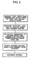
FIG. 2 is an explanatory flowchart showing steps of the assembly; -
FIG. 3 is a sectional view of the bearing; -
FIG. 4 is a view as viewed from rightward inFIG. 3 ; -
FIG. 5 is a partial sectional view showing a first holder taken out; -
FIG. 6 is a sectional view taken along the line 6-6 inFIG. 5 ; -
FiG. 7 is a partial sectional view showing a second holder taken out; -
FIG. 8 is a sectional view taken along the line 8-8 inFIG. 7 ; -
FIG. 9 is a sectional view of a first step in the assembling operation, showing a state where some taper-rollers are held by the first holder; -
FIG. 10 is a sectional view similarly showing a next step thereof; -
FIG. 11 is a sectional view similarly showing a subsequent step; -
FIG, 12 is a sectional view similarly showing a last step; -
FIG. 13 shows a proposed double row taper-roller bearing; -
FIG. 14 is a sectional view showing an assembling step; and -
FIG. 15 is a sectional view similarly showing a next step. - A double row taper-roller bearing for a hub unit for an automobile will hereinafter be described with reference to the accompanying drawings.
-
FIG.1 is an explanatory view showing a method of controlling an axial gap when assembling a taper-roller bearing of a hub unit for fitting a driving front wheel of an automobile. - A
hub 1 of the hub unit integrally includes, as the integral parts, aflange 11 for fixing a rim (not shown) of the front wheel, and acylindrical member 12 extending in an axial direction, to be formed with the taper-roller bearing along an outer periphery thereof and to fix along an inner periphery thereof an axle (unillustrated). - The
flange 11 is formed with a proper number ofbolt holes 13, and the rim of the wheel (not shown) is fixed bybolts 14. The axle is, as described above, inserted into acentral hole 15 of thecylindrical member 12 extending in the axial direction, and thehub 11 is fixed to the axle by bolts (unillustrated) in abolt hole 16 formed in the central portion of thehub 11. The hub and the wheel, i.e., the wheel and the axle integrally rotate. - The
cylindrical member 12 serving as a first inner ring member extends in the axial direction, of which an outer periphery is formed with afirst track surface 17 configuring a part of a tapered shape opened toward the flange. Thecylindrical member 12 has alarge collar portion 18 extending from a side end on a large-diameter-side of thefirst track surface 17. - An
outer ring 20 is disposed outside in the radial direction of thecylindrical member 12. Theouter ring 20 is formed with a firstinside track surface 21 constituting a part of the tapered shape, facing to thefirst track surface 17 formed along thecylindrical member 12 serving as a first inner ring member. A predetermined number of first taper-rollers 40 held by a first cage orholder 30 are interposed between thefirst track surface 17 of the first inner ring member defined as thecylindrical member 12 and the first insidetrack surface 21 of theouter ring 20. Thefirst holder 30 and the first taper-rollers 40 are combined to constitute a first roller row. - The
outer ring 20 is formed with a secondinside track surface 22 configuring a part of the tapered shape opened opposite to the first insidetrack surface 21, and spaced at a predetermined axial distance away from the first inside track surface described above. - On the other hand, a first inner ring member constructed of the
cylindrical member 12 has a small-diametercylindrical portion 12a, formed at a portion facing in the axial direction to the second insidetrack surface 22 of theouter ring 20, of which an outer periphery is formed with a cylindrical surface with a substantially uniform diameter. A secondinner ring member 12b is fixedly fitted to this small-diametercylindrical portion 12a. - An outer periphery of the second
inner ring member 12b is formed with asecond track surface 12c constituting a part of the tapered shape, facing to the second insidetrack surface 22 of theouter ring 20. A predetermined number of second taper-rollers 50 held by a second cage orholder 51 are interposed between the second insidetrack surface 22 of theouter ring 20 and thesecond track surface 12c of the secondinner ring member 12b in such a way that therollers 50 roll while being kept in contact with these track surfaces. The second taper-rollers 50 and thesecond holder 51 are combined to constitute a second roller row. Theouter ring 20 has aflange 25 substantially at the center of the outer periphery thereof. Theflange 25 is formed with ahole 26 through which a bolt (not shown) is inserted to fix the outer ring to a knuckle of a suspension system on the car body side. - Thus, the hub unit is formed with the double row taper-roller bearing.
- Next, the method of assembling the double row taper-roller bearing will be explained.
- To start with, the first roller row composed of the first taper-
rollers 40 held by thefirst holder 30, is fitted onto thefirst track surface 17 of the firstinner ring member 12, and then theouter ring 20 is fitted to the outer portion thereof. - Next, the second roller row composed of the second taper-
rollers 50 held by thesecond holder 51 is so fitted as to come into contact with the secondinside track surface 22 of theouter ring 20. - Subsequently, a master member of the second inner ring member, which has the known dimensions and a positive axial gap with respect to the assembled taper-roller bearing, is inserted into a space formed between the second roller row and the small-diameter
cylindrical portion 12a. - In this state, a tentative axial gap is measured, and, as a next step, dimensions of the second inner ring member for obtaining a negative axial gap on a desired specification are arithmetically obtained based on a measured result of the tentative axial gap.
- A second
inner ring member 12b having proper dimensions is chosen out of a stocker of the second inner ring members, corresponding to this arithmetic result, and the second inner ring member selected as a substitute for the master member is incorporated, thereby obtaining the double row taper-roller bearing based on the desired specification. - Note that the second
inner ring member 12b may be selected and incorporated either by a manual work or by an automatic operation. - In accordance with the above described, the negative axial gap of the double row taper-roller bearing, which cannot be ensured after the assembly, can be controlled by use of the master member before the assembly.
-
FIGS. 3-8 Illustrate an embodiment of the hub unit for the automobile accordingtothe present invention. Thehub unit 10 for the automobile is constructed of a hub body 11 a, anInner ring member 12 externally fitted to the hub body 11 a, anouter ring 20 disposed along the peripheries of the hub body 11 a and of theinner ring member 12b, a plurality of taper-rollers inner ring member 12b and an inner peripheral surface of theouter ring 20, afirst seal ring 15a for hermetically sealing between an inner peripheral surface of one side end of theouter ring 20 and an outer peripheral surface of an intermediate portion of the hub body 11a, and asecond seal ring 15b for hermetically sealing between an inner peripheral surface of the other side end of theouter ring 20 and an outer peripheral surface of a side end oftheinner ring member 12b. In the embodiment illustrated, a single seal ring is used as thefirst seal ring 15a, and a combined seal ring is used as thesecond seal ring 15b. - The hub body 11 a among those components has a
flange 11 for supporting the wheel on an outer peripheral surface of one side end (an outer side end in the widthwise direction in a state of being assembled to the car body, corresponding to a left side end inFIG. 1 ). Further, a firstinner ring track 17, taking a configuration of tapered convex surface, for configuring the taper-roller bearing 18a of the first row, is formed directly on the outer peripheral surface of the intermediate portion of the hub body 11 a. Furthermore, a small-diameter steppedportion 12a is provided on the outer peripheral surface of the other side end (an inner side end in the widthwise direction in the state of being assembled to the car body, corresponding to a right side end inFIG. 3 ) of the hub body 11 a. An outer peripheral surface of the small-diameter steppedportion 12a takes a cylindrical shape concentric with the hub body 11 a. Further, in the embodiment illustrated, theautomobile hub unit 10 for supporting the driving wheel is provided, and hence aspline hole 21 a for spline-engaging with a side end of a drive axle is provided in a central portion of the hub body 11 a. - Further, the
inner ring member 12b includes a secondinner ring track 12c assuming a configuration of tapered convex surface and formed along the outer peripheral surface, for configuring the taper-roller bearing 22a of the second row, and fixedly fitted to an outer portion of the small-diameter steppedportion 12a of the hub body 11a. An inclined direction of the secondinner ring track 12c is set opposite to an inclined direction of the firstinner ring track 17. Further, a proximal end (a right side end inFIG. 3 ) of theinner ring member 12b protrude slightly from the other side end surface (a right side end surface inFIG. 3 ) of the hub body 11 a in a state of letting a front side end surface (a left side end surface inFIG. 3 ) of theinner ring 12b impinge upon a steppedsurface 24 of the small-diameter steppedportion 12a. In the state of being assembled to the car body, a side end surface of a constant velocity joint or a stepped portion formed at the side end portion of the drive axle, impinge upon the side end surface of the proximal end of theinner ring 12b which thus protrudes from the hub body 11 a, thereby preventing theinner ring 12b from disengaging from the small-diameter steppedportion 12a. - Moreover, the inner peripheral surface of the
outer ring 20 is formed with first and second outer ring tracks 21, 22, each taking a configuration of tapered concave surface, for configuring the taper-roller bearings outer ring 20 is provided with an outward-flange-likefitting portion 25 for fixing theouter ring 20 to an unillustrated suspension. - Further, some taper-
rollers 40, 40 (a left half inFIG. 3 ) among the plurality of taper-rollers inner ring track 17 and the firstouter ring track 21 in a state of being so held by the first holder as to be reliable. - While on the other hand, the remaining taper-
rollers 50, 50 (a right half inFIG. 1 ) among the plurality of taper-rollers inner ring track 12c and the secondouter ring track 22 in a state being so held by thesecond holder 51 as to be reliable. - Then, the
first holder 30, in a state of holding some taper-rollers rollers rollers FIGS. 5 and 6 is used as thefirst holder 30. Thefirst holder 30 is formed in a partially tapered cylindrical shape on the whole by injection-molding a synthetic resin exhibiting elasticity, and haspockets columns rollers pockets - Further, an outer peripheral surface of each of the
columns rollers pockets rollers rollers pockets columns first holder 30. Thecolumns rollers - On the other hand, in the state where the
pockets rollers pockets columns rollers first holder 30 prevents the taper-rollers rollers - On the other hand, the
second holder 51 assumes a configuration as shown inFIGS. 7 and 8 , and, in the state of holding in a reliable manner the remaining taper-rollers rollers rollers holder 107 incorporated into the proposed structure shown inFIGS. 13 - 15 . Thesecond holder 51 is formed in a partially tapered cylindrical shape on the whole by injection-molding a synthetic resin, and haspockets columns columns rollers pockets rollers rollers pockets second holder 51. The taper-rollers pockets inner ring 12b is inserted on the minor-diameter side of each of the taper-rollers rollers pockets - Next, the method of assembling the
automobile hub unit 10 having the construction described above will be explained with reference toFIGS. 9 - 12 in addition toFIGS. 3 - 8 . To start with, as illustrated inFIG. 9 , some taper-rollers rollers first holder 30. In this state, these taper-rollers first holder 30 without being separated. It is therefore feasible to easily carry it in the factory. Then, the taper-rollers FIG. 10 , disposed inside the firstouter ring track 21 on the inner peripheral surface of theouter ring 20. Further, after some taper-rollers outer ring track 21, thefirst seal ring 15a is fixedly fitted to the inner peripheral surface of one side end of theouter ring 20. In this state, the taper-rollers first holder 30 are combined without being separated. - - Accordingly, it is still possible to facilitate the carrying operation in the factory.
- Thus, some taper-
rollers outer ring 20, and thefirst seal ring 15a is fixedly fitted inside, in which state as shown inFIGS. 10 and11 the hub body 11 a is inserted inside theouter ring 20. This inserting operation, as shown inFIG. 11 , continues till there is attained a state where the firstinner ring track 17 is positioned inwardly of some taper-rollers rollers first seal ring 15a comes into contact with an entire periphery of an area, between theflange 11 and the firstinner ring track 17, of the surface of theouter ring 20. During this inserting operation, some taper-rollers first holder 30 remain attached to the firstouter ring track 21 without coming off inwards in the diametrical direction of thefirst holder 30. Accordingly, the inserting operation can be smoothly executed with no necessity especially for such a laborious work as to press the taper-rollers - Next, as illustrated in
FIGS. 11 and12 , theinner ring member 12b is inserted inside theouter ring 20 in a state where the remaining taper-rollers rollers inner ring track 12c by thesecond holder 51. Then, with this inserting operation, theinner ring member 12b is fixedly fitted to the outer portion ofthe small-diameter steppedportion 12a of the hub body 11 a. Then, finally, as illustrated inFIGS. 12 and3 , thesecond seal ring 15b is attached between the outer peripheral surface of the side end of theinner ring member 12b and the inner peripheral surface of the side end of theouter ring 20. Note that a pre-load applied to each of the taper-roller bearings 18a of the first and second rows may be arbitrarily readily adjusted by changing a grinding quantity of a part of theinner ring 12b. - As discussed above, according to the automobile hub unit and the assembling method thereof, the costs for the automobile hub unit can be reduced by assembling the novel third-generation automobile hub unit at a high efficiency.
Claims (1)
- Method of assemblinga hub unit (1, 10) for an automobile, comprising:a hub body (11a);an inner ring member (12b) fixedly fitted on an outer portion of said hub body (11 a);an outer ring (20) disposed along circumferences of said hub body (11a) and of said inner ring member (12b);a plurality of taper-rollers (40, 50) provided between outer peripheral surfaces (17, 12c) of said hub body (11a) and of said inner ring member (12b), and an inner peripheral surface (21, 22) of said outer ring (20);a first seal ring (15a) for hermetically sealing between an inner peripheral surface of one side end of said outer ring (20) and an outer peripheral surface of an intermediate portion (18) of said hub body (11a); anda second seal ring (15b) for hermetically sealing between an inner peripheral surface of the other side end of said outer ring (20) and an outer peripheral surface of a side end of said inner ring member (12b),
wherein said hub body (11a) includes a flange (11), provided along an outer peripheral surface of one side end thereof, for supporting a wheel, a first inner ring track (17) taking a configuration of tapered convex surface anddirectly formed along an outer peripheral surface of an intermediate portion thereof, for configuring said taper-roller bearing (18a) of a first row, and a small-diameter stepped portion (12a) provided on an outer peripheral surface of the other side end thereof,said inner ring member (12b) includes a second inner ring track (12c), taking a configuration of tapered convex surface and formed along an outer peripheral surface thereof, for configuring said taper-roller bearing (18a) of a second row, and is fixedly fitted to an outer portion of said small-diameter stepped portion (12a),said outer ring (20) includes first and second outer ring tracks (21, 22), each taking a configuration of tapered concave surface and formed along an inner peripheral surface thereof, for configuring said taper-roller bearings (18a) of the first and second rows,some of said plurality of taper-rollers (40) are disposed between said first inner ring track (17) and said first outer ring track (21) in a state of so being held by said first holder (30) as to be reliable, and said remaining taper-rollers (50) are disposed between said second inner ring track (12c) and said second outer ring track (22) in a state of being so held by said second holder (51) as to be reliable,and wherein said first holder (30) prevents said respective taper-rollers (40) from coming off inwards in the diametrical direction in a state of holding some of said plurality of taper-rollers (40), and said second holder (51) prevents said respective taper-rollers (50) from coming off outwards in the diametrical direction in a state of holding said remaining taper-rollers (50) among said plurality of taper-rollers (40),
comprising the steps of:holding some of said plurality of taper-rollers (40) by said first holder (30) anddisposing said taper-rollers (40) inside of said first outer ring track (21) along said inner peripheral surface of said outer ring (20);inserting said hub body (11 a) inside of said outer ring (20) in a state of fixedly fitting said first seal ring (15a) to said inner peripheral surface of one side end of said outer ring (20) till said first inner ring track (17) is positioned inwardly of some of said plurality of taper-rollers (40);subsequently fitting said inner ring member (12b) to said outer portion of said small-diameter stepped portion (12a) of said hub body (11 a) while being inserted inside of said outer ring (20) in a state where said remaining taperrollers (50) among said plurality of taper-rollers (40) are held along a circumference of said second inner ring track (12c) by said second holder (51); andfinally attaching said second seal ring (15b) between said outer peripheral surface of an end of said inner ring member (12b) and said inner peripheral surface of said side end of said outer ring (20).
Applications Claiming Priority (5)
| Application Number | Priority Date | Filing Date | Title |
|---|---|---|---|
| JP24652698 | 1998-08-18 | ||
| JP24652698A JP4178612B2 (en) | 1998-08-18 | 1998-08-18 | Assembly method of double row tapered roller bearing |
| JP23793898 | 1998-08-24 | ||
| JP10237398A JP2000065049A (en) | 1998-08-24 | 1998-08-24 | Automotive hub unit and assembling method for it |
| EP99116237A EP0980985B1 (en) | 1998-08-18 | 1999-08-17 | Method of assembling a double row taper-bearing |
Related Parent Applications (1)
| Application Number | Title | Priority Date | Filing Date |
|---|---|---|---|
| EP99116237A Division EP0980985B1 (en) | 1998-08-18 | 1999-08-17 | Method of assembling a double row taper-bearing |
Publications (4)
| Publication Number | Publication Date |
|---|---|
| EP1473474A2 EP1473474A2 (en) | 2004-11-03 |
| EP1473474A3 EP1473474A3 (en) | 2005-01-12 |
| EP1473474B1 EP1473474B1 (en) | 2006-01-18 |
| EP1473474B2 true EP1473474B2 (en) | 2009-08-12 |
Family
ID=26533189
Family Applications (2)
| Application Number | Title | Priority Date | Filing Date |
|---|---|---|---|
| EP04015614A Expired - Lifetime EP1473474B2 (en) | 1998-08-18 | 1999-08-17 | A hub unit for an automobile |
| EP99116237A Expired - Lifetime EP0980985B1 (en) | 1998-08-18 | 1999-08-17 | Method of assembling a double row taper-bearing |
Family Applications After (1)
| Application Number | Title | Priority Date | Filing Date |
|---|---|---|---|
| EP99116237A Expired - Lifetime EP0980985B1 (en) | 1998-08-18 | 1999-08-17 | Method of assembling a double row taper-bearing |
Country Status (3)
| Country | Link |
|---|---|
| US (2) | US6287015B1 (en) |
| EP (2) | EP1473474B2 (en) |
| DE (2) | DE69929480T3 (en) |
Families Citing this family (26)
| Publication number | Priority date | Publication date | Assignee | Title |
|---|---|---|---|---|
| WO2002077475A1 (en) * | 2001-02-06 | 2002-10-03 | The Timken Company | Gauge and process for adjusting bearings |
| US6868609B1 (en) * | 2002-01-15 | 2005-03-22 | Torque-Traction Technologies, Inc. | Method and apparatus for preloading pinion bearings |
| US6659650B2 (en) | 2002-01-28 | 2003-12-09 | The Timken Company | Wheel bearing with improved cage |
| US6588119B1 (en) * | 2002-02-26 | 2003-07-08 | The Timken Company | Compact gauge and process for adjusting bearings |
| US6581288B1 (en) | 2002-04-17 | 2003-06-24 | The Timken Company | Method of assembling a package bearing and an assembly tool therefore |
| JP2004263722A (en) * | 2003-02-07 | 2004-09-24 | Koyo Seiko Co Ltd | Method of assembling rolling bearing device |
| JP4513295B2 (en) | 2003-02-07 | 2010-07-28 | 株式会社ジェイテクト | Method for assembling rolling bearing device |
| JP2004340242A (en) * | 2003-05-15 | 2004-12-02 | Ntn Corp | Tapered roller bearing device for wheel |
| DE602006018399D1 (en) | 2005-08-25 | 2011-01-05 | Ntn Toyo Bearing Co Ltd | Tapered roller bearings |
| WO2007083688A1 (en) * | 2006-01-20 | 2007-07-26 | Jtekt Corporation | Method for manufacturing hub unit and hub unit |
| JP4697006B2 (en) | 2006-03-30 | 2011-06-08 | 株式会社ジェイテクト | Roller bearing cage and tapered roller bearing |
| DE102007009918A1 (en) * | 2007-02-27 | 2008-09-04 | Ab Skf | Wheel bearing for bearing of wheels rotating around axis of rotation, has tapered roller bearing with tapered-roller row and inclined ball bearing with two ball races |
| JP4770760B2 (en) * | 2007-03-15 | 2011-09-14 | 株式会社ジェイテクト | Method and apparatus for assembling rolling bearing device |
| JP2009078603A (en) * | 2007-09-25 | 2009-04-16 | Jtekt Corp | Roller bearing device for wheel |
| DE102007049087A1 (en) | 2007-10-12 | 2009-04-23 | Rothe Erde Gmbh | Radially and axially loadable rolling bearing |
| JP5134340B2 (en) * | 2007-11-06 | 2013-01-30 | Ntn株式会社 | Wheel bearing device |
| DE102007060407A1 (en) | 2007-12-14 | 2009-06-18 | Schaeffler Kg | Bearing assembly and motor vehicle with a bearing assembly |
| JP2009143466A (en) * | 2007-12-17 | 2009-07-02 | Jtekt Corp | Rolling bearing device for wheel |
| US8845203B2 (en) * | 2008-11-06 | 2014-09-30 | Kyklos Bearing International, Inc. | Wheel bearing assembly |
| US20110135233A1 (en) * | 2009-12-04 | 2011-06-09 | Gm Global Technology Operations, Inc. | Apparatus with secondary load path for vehicle wheel bearing assembly |
| CN102500996A (en) * | 2011-09-30 | 2012-06-20 | 沈阳黎明航空发动机(集团)有限责任公司 | Assembling method for three-fulcrum bearing of aircraft engine |
| WO2014104132A1 (en) | 2012-12-25 | 2014-07-03 | 日本精工株式会社 | Tapered roller bearing |
| EP2982878B1 (en) | 2013-04-04 | 2018-08-08 | NSK Ltd. | Resin cage for tapered roller bearing and tapered roller bearing including the resin cage |
| DE102013212989B4 (en) * | 2013-07-03 | 2015-10-08 | Aktiebolaget Skf | engine assembly |
| CN104061388A (en) * | 2014-06-19 | 2014-09-24 | 德清恒丰机械有限公司 | Novel flange forge piece for automobile |
| JP2022052298A (en) | 2020-09-23 | 2022-04-04 | Ntn株式会社 | Assembling method and assembling device of hub bearing |
Citations (12)
| Publication number | Priority date | Publication date | Assignee | Title |
|---|---|---|---|---|
| DE607263C (en) † | 1933-10-04 | 1934-12-20 | Timken Roller Bearing Co | Tapered roller bearings |
| EP0007786A1 (en) † | 1978-07-24 | 1980-02-06 | The Timken Company | Wheel mounting and tapered roller bearing therefor |
| DE2928269A1 (en) † | 1979-07-13 | 1981-01-29 | Skf Kugellagerfabriken Gmbh | Roller bearings distance piece system - uses separate distance pieces located between rollers with tongues which snap into ring grooves to permit easy assembly of bearing |
| US4425011A (en) † | 1982-06-07 | 1984-01-10 | The Timken Company | Polymer cage for a high speed tapered roller bearing |
| DE3605812A1 (en) † | 1986-02-22 | 1987-08-27 | Kugelfischer G Schaefer & Co | CAEFIG FOR Tapered Roller Bearings that can be manufactured with the help of two axial slides |
| DE3141813C2 (en) † | 1980-03-31 | 1989-01-12 | The Timken Co., Canton, Ohio, Us | |
| DE8908581U1 (en) † | 1989-07-14 | 1989-08-31 | SKF GmbH, 8720 Schweinfurt | Pocket cage for rolling bearings |
| DE4016492A1 (en) † | 1989-05-22 | 1990-11-29 | Koyo Seiko Co | RADIAL ROLLER BEARING |
| US5037214A (en) † | 1988-02-29 | 1991-08-06 | The Timken Company | Double row tapered roller bearing assembly |
| DE4206861A1 (en) † | 1991-03-08 | 1992-09-10 | Skf Ind Spa | Conical roller cage for conical roller bearing - comprises inner and outer ring crowns, and rib crown for distancing rollers and connection of both crowns which have cylindrical edges |
| DE69402621T2 (en) † | 1993-06-24 | 1997-10-16 | Robert Bosch Technology Corp., Farmington Hills, Mich. | Vehicle wheel assembly |
| US6126322A (en) † | 1998-03-20 | 2000-10-03 | Ntn Corporation | Vehicle wheel supporting structure |
Family Cites Families (25)
| Publication number | Priority date | Publication date | Assignee | Title |
|---|---|---|---|---|
| US1761490A (en) * | 1927-06-03 | 1930-06-03 | Otto H Penner | Adjustable double roller bearing |
| US1916233A (en) * | 1932-06-16 | 1933-07-04 | Timken Roller Bearing Co | Bearing positioning means |
| US2071945A (en) * | 1933-03-06 | 1937-02-23 | American Steel Foundries | Wheel and axle assembly |
| US2003339A (en) * | 1934-02-07 | 1935-06-04 | Timken Roller Bearing Co | Axle bearing |
| US2118756A (en) * | 1937-03-29 | 1938-05-24 | Timken Roller Bearing Co | Apparatus for use in effecting adjustments of roller bearing parts |
| US2606799A (en) * | 1950-08-14 | 1952-08-12 | Timken Roller Bearing Co | Adjustable double roller bearing |
| US2627120A (en) * | 1950-11-15 | 1953-02-03 | Timken Roller Bearing Co | Spacer gauge for adjustable roller bearings |
| US2796658A (en) * | 1953-11-02 | 1957-06-25 | Sheffield Corp | Mjethod of gauging and selecting cooperating parts |
| NL140620B (en) * | 1968-04-10 | 1973-12-17 | Skf Svenska Kullagerfab Ab | AXLE CONSTRUCTION FOR A NON-DRIVEN WHEEL OF A MOTOR VEHICLE. |
| US3720450A (en) * | 1971-04-05 | 1973-03-13 | Timken Co | Tapered roller retainer and method of bearing assembly |
| US3733111A (en) * | 1971-06-29 | 1973-05-15 | Trw Inc | Tapered roller bearing assembly with antifriction molded cage |
| NL7710564A (en) * | 1977-09-28 | 1979-03-30 | Skf Ind Trading & Dev | REVERSING BEARING. |
| US4336641A (en) * | 1979-03-16 | 1982-06-29 | The Timken Company | Bearing setting process |
| DE3540224A1 (en) * | 1985-11-13 | 1987-05-14 | Kugelfischer G Schaefer & Co | Double row angular contact ball bearing |
| IT1182697B (en) * | 1985-11-22 | 1987-10-05 | Riv Officine Di Villar Perosa | TAPER ROLLER BEARING PARTICULARLY FOR RAILWAY USE |
| JPH0180503U (en) * | 1987-11-19 | 1989-05-30 | ||
| IT1259355B (en) * | 1992-03-20 | 1996-03-12 | Skf Ind Spa | ROLLING BEARING, IN PARTICULAR FOR A VEHICLE WHEEL GROUP |
| US5226737A (en) * | 1992-05-26 | 1993-07-13 | General Motors Corporation | Two row angular contact wheel bearing with improved load capacity |
| US5206993A (en) * | 1992-05-26 | 1993-05-04 | General Motors Corporation | Method of assembling two row angular contact bearing with improved axial end play |
| WO1995012072A1 (en) * | 1993-10-28 | 1995-05-04 | Ntn Corporation | Axle bearing device and method for measuring a bearing gap |
| US5494358A (en) * | 1994-02-09 | 1996-02-27 | The Timken Company | Package bearing |
| DE19602407C1 (en) * | 1996-01-24 | 1997-08-21 | Gkn Automotive Ag | Part which drives and forms bearing with vehicle wheel |
| JP3699249B2 (en) * | 1997-07-28 | 2005-09-28 | Ntn株式会社 | Hub unit bearing and manufacturing method thereof |
| US6058767A (en) * | 1998-02-27 | 2000-05-09 | The Timken Company | Measurement of wheel bearing end play |
| JP2000211310A (en) * | 1999-01-21 | 2000-08-02 | Ntn Corp | Wheel support structure |
-
1999
- 1999-08-17 EP EP04015614A patent/EP1473474B2/en not_active Expired - Lifetime
- 1999-08-17 DE DE69929480T patent/DE69929480T3/en not_active Expired - Lifetime
- 1999-08-17 DE DE69928051T patent/DE69928051T2/en not_active Expired - Lifetime
- 1999-08-17 EP EP99116237A patent/EP0980985B1/en not_active Expired - Lifetime
- 1999-08-18 US US09/376,488 patent/US6287015B1/en not_active Expired - Lifetime
-
2001
- 2001-04-30 US US09/843,953 patent/US6502307B2/en not_active Expired - Lifetime
Patent Citations (12)
| Publication number | Priority date | Publication date | Assignee | Title |
|---|---|---|---|---|
| DE607263C (en) † | 1933-10-04 | 1934-12-20 | Timken Roller Bearing Co | Tapered roller bearings |
| EP0007786A1 (en) † | 1978-07-24 | 1980-02-06 | The Timken Company | Wheel mounting and tapered roller bearing therefor |
| DE2928269A1 (en) † | 1979-07-13 | 1981-01-29 | Skf Kugellagerfabriken Gmbh | Roller bearings distance piece system - uses separate distance pieces located between rollers with tongues which snap into ring grooves to permit easy assembly of bearing |
| DE3141813C2 (en) † | 1980-03-31 | 1989-01-12 | The Timken Co., Canton, Ohio, Us | |
| US4425011A (en) † | 1982-06-07 | 1984-01-10 | The Timken Company | Polymer cage for a high speed tapered roller bearing |
| DE3605812A1 (en) † | 1986-02-22 | 1987-08-27 | Kugelfischer G Schaefer & Co | CAEFIG FOR Tapered Roller Bearings that can be manufactured with the help of two axial slides |
| US5037214A (en) † | 1988-02-29 | 1991-08-06 | The Timken Company | Double row tapered roller bearing assembly |
| DE4016492A1 (en) † | 1989-05-22 | 1990-11-29 | Koyo Seiko Co | RADIAL ROLLER BEARING |
| DE8908581U1 (en) † | 1989-07-14 | 1989-08-31 | SKF GmbH, 8720 Schweinfurt | Pocket cage for rolling bearings |
| DE4206861A1 (en) † | 1991-03-08 | 1992-09-10 | Skf Ind Spa | Conical roller cage for conical roller bearing - comprises inner and outer ring crowns, and rib crown for distancing rollers and connection of both crowns which have cylindrical edges |
| DE69402621T2 (en) † | 1993-06-24 | 1997-10-16 | Robert Bosch Technology Corp., Farmington Hills, Mich. | Vehicle wheel assembly |
| US6126322A (en) † | 1998-03-20 | 2000-10-03 | Ntn Corporation | Vehicle wheel supporting structure |
Also Published As
| Publication number | Publication date |
|---|---|
| DE69929480D1 (en) | 2006-04-06 |
| EP0980985A2 (en) | 2000-02-23 |
| DE69928051T2 (en) | 2006-04-20 |
| DE69929480T3 (en) | 2009-11-19 |
| US6502307B2 (en) | 2003-01-07 |
| DE69929480T2 (en) | 2006-07-13 |
| DE69928051D1 (en) | 2005-12-08 |
| EP0980985B1 (en) | 2005-11-02 |
| US6287015B1 (en) | 2001-09-11 |
| US20010016092A1 (en) | 2001-08-23 |
| EP1473474A3 (en) | 2005-01-12 |
| EP1473474B1 (en) | 2006-01-18 |
| EP1473474A2 (en) | 2004-11-03 |
| EP0980985A3 (en) | 2001-01-03 |
Similar Documents
| Publication | Publication Date | Title |
|---|---|---|
| EP1473474B2 (en) | A hub unit for an automobile | |
| EP0849481B1 (en) | Expandable bearing retainer | |
| KR101078550B1 (en) | Method for mounting an opposed path joint | |
| JP3735926B2 (en) | Wheel support hub unit | |
| EP1607646B1 (en) | Method for assembling rolling bearing device | |
| JPH11303882A (en) | Constant speed joint | |
| JP2002227849A (en) | Tapered roller bearing retainer and double row tapered roller bearing unit | |
| JP4501324B2 (en) | Assembly method of double row tapered roller bearing unit | |
| JP2000065049A (en) | Automotive hub unit and assembling method for it | |
| JP4078945B2 (en) | Rolling bearing device | |
| JP4244955B2 (en) | Assembly method for automotive hub unit | |
| JP4042528B2 (en) | Rolling bearing device | |
| JP4239542B2 (en) | Rolling bearing device | |
| JP2000094902A (en) | Hub unit for automobile and assembly method therefor | |
| JP2000145805A (en) | Constant velocity universal joint and automobile hub unit with constant velocity universal joint | |
| JP2001163003A (en) | Bearing unit for driving wheel and method for manufacturing connecting member therefor | |
| JP4178612B2 (en) | Assembly method of double row tapered roller bearing | |
| JP2003056580A (en) | Bearing device for axle | |
| JP3893933B2 (en) | Rotating support device for wheel and assembling method thereof | |
| JP4123579B2 (en) | How to assemble constant velocity joints | |
| JP2004263722A (en) | Method of assembling rolling bearing device | |
| JP4815712B2 (en) | Axle bearing device | |
| JPH10281152A (en) | Double row angular ball bearing | |
| JP2005083496A (en) | Conical roller bearing device for wheel and its assembling method | |
| JP2004176747A (en) | Double row tapered roller bearing unit for supporting wheel |
Legal Events
| Date | Code | Title | Description |
|---|---|---|---|
| PUAI | Public reference made under article 153(3) epc to a published international application that has entered the european phase |
Free format text: ORIGINAL CODE: 0009012 |
|
| AC | Divisional application: reference to earlier application |
Ref document number: 0980985 Country of ref document: EP Kind code of ref document: P |
|
| AK | Designated contracting states |
Kind code of ref document: A2 Designated state(s): DE |
|
| PUAL | Search report despatched |
Free format text: ORIGINAL CODE: 0009013 |
|
| AK | Designated contracting states |
Kind code of ref document: A3 Designated state(s): DE |
|
| RIC1 | Information provided on ipc code assigned before grant |
Ipc: 7F 16C 33/48 B Ipc: 7B 60B 27/00 B Ipc: 7F 16C 43/04 B Ipc: 7F 16C 25/06 B Ipc: 7F 16C 19/38 A |
|
| 17P | Request for examination filed |
Effective date: 20050204 |
|
| GRAP | Despatch of communication of intention to grant a patent |
Free format text: ORIGINAL CODE: EPIDOSNIGR1 |
|
| GRAP | Despatch of communication of intention to grant a patent |
Free format text: ORIGINAL CODE: EPIDOSNIGR1 |
|
| AKX | Designation fees paid |
Designated state(s): DE |
|
| GRAS | Grant fee paid |
Free format text: ORIGINAL CODE: EPIDOSNIGR3 |
|
| GRAA | (expected) grant |
Free format text: ORIGINAL CODE: 0009210 |
|
| RIN1 | Information on inventor provided before grant (corrected) |
Inventor name: SHIBUYA, EISHI Inventor name: KOBAYASHI, KATSUMI Inventor name: KOMABA, MICHIO |
|
| AC | Divisional application: reference to earlier application |
Ref document number: 0980985 Country of ref document: EP Kind code of ref document: P |
|
| AK | Designated contracting states |
Kind code of ref document: B1 Designated state(s): DE |
|
| REF | Corresponds to: |
Ref document number: 69929480 Country of ref document: DE Date of ref document: 20060406 Kind code of ref document: P |
|
| PLBI | Opposition filed |
Free format text: ORIGINAL CODE: 0009260 |
|
| PLAB | Opposition data, opponent's data or that of the opponent's representative modified |
Free format text: ORIGINAL CODE: 0009299OPPO |
|
| PLAX | Notice of opposition and request to file observation + time limit sent |
Free format text: ORIGINAL CODE: EPIDOSNOBS2 |
|
| 26 | Opposition filed |
Opponent name: KOHL, THOMAS |
|
| R26 | Opposition filed (corrected) |
Opponent name: SKF GMBH Effective date: 20061017 |
|
| PLBB | Reply of patent proprietor to notice(s) of opposition received |
Free format text: ORIGINAL CODE: EPIDOSNOBS3 |
|
| PUAH | Patent maintained in amended form |
Free format text: ORIGINAL CODE: 0009272 |
|
| STAA | Information on the status of an ep patent application or granted ep patent |
Free format text: STATUS: PATENT MAINTAINED AS AMENDED |
|
| 27A | Patent maintained in amended form |
Effective date: 20090812 |
|
| AK | Designated contracting states |
Kind code of ref document: B2 Designated state(s): DE |
|
| PGFP | Annual fee paid to national office [announced via postgrant information from national office to epo] |
Ref country code: DE Payment date: 20180807 Year of fee payment: 20 |
|
| REG | Reference to a national code |
Ref country code: DE Ref legal event code: R071 Ref document number: 69929480 Country of ref document: DE |