EP1473465A1 - Compressor - Google Patents
Compressor Download PDFInfo
- Publication number
- EP1473465A1 EP1473465A1 EP04251692A EP04251692A EP1473465A1 EP 1473465 A1 EP1473465 A1 EP 1473465A1 EP 04251692 A EP04251692 A EP 04251692A EP 04251692 A EP04251692 A EP 04251692A EP 1473465 A1 EP1473465 A1 EP 1473465A1
- Authority
- EP
- European Patent Office
- Prior art keywords
- inlet
- tubular wall
- compressor
- upstream
- impeller wheel
- Prior art date
- Legal status (The legal status is an assumption and is not a legal conclusion. Google has not performed a legal analysis and makes no representation as to the accuracy of the status listed.)
- Granted
Links
- 238000011144 upstream manufacturing Methods 0.000 claims abstract description 37
- 239000000411 inducer Substances 0.000 claims abstract description 13
- 230000004323 axial length Effects 0.000 description 5
- 230000007423 decrease Effects 0.000 description 2
- 238000012986 modification Methods 0.000 description 2
- 230000004048 modification Effects 0.000 description 2
- 230000000712 assembly Effects 0.000 description 1
- 238000000429 assembly Methods 0.000 description 1
- 238000005266 casting Methods 0.000 description 1
- 230000003247 decreasing effect Effects 0.000 description 1
- 238000010348 incorporation Methods 0.000 description 1
- 238000004519 manufacturing process Methods 0.000 description 1
- 238000000034 method Methods 0.000 description 1
Images


Classifications
-
- F—MECHANICAL ENGINEERING; LIGHTING; HEATING; WEAPONS; BLASTING
- F04—POSITIVE - DISPLACEMENT MACHINES FOR LIQUIDS; PUMPS FOR LIQUIDS OR ELASTIC FLUIDS
- F04D—NON-POSITIVE-DISPLACEMENT PUMPS
- F04D29/00—Details, component parts, or accessories
- F04D29/40—Casings; Connections of working fluid
- F04D29/42—Casings; Connections of working fluid for radial or helico-centrifugal pumps
- F04D29/4206—Casings; Connections of working fluid for radial or helico-centrifugal pumps especially adapted for elastic fluid pumps
- F04D29/4213—Casings; Connections of working fluid for radial or helico-centrifugal pumps especially adapted for elastic fluid pumps suction ports
-
- H—ELECTRICITY
- H02—GENERATION; CONVERSION OR DISTRIBUTION OF ELECTRIC POWER
- H02J—CIRCUIT ARRANGEMENTS OR SYSTEMS FOR SUPPLYING OR DISTRIBUTING ELECTRIC POWER; SYSTEMS FOR STORING ELECTRIC ENERGY
- H02J7/00—Circuit arrangements for charging or depolarising batteries or for supplying loads from batteries
- H02J7/34—Parallel operation in networks using both storage and other dc sources, e.g. providing buffering
- H02J7/35—Parallel operation in networks using both storage and other dc sources, e.g. providing buffering with light sensitive cells
-
- F—MECHANICAL ENGINEERING; LIGHTING; HEATING; WEAPONS; BLASTING
- F04—POSITIVE - DISPLACEMENT MACHINES FOR LIQUIDS; PUMPS FOR LIQUIDS OR ELASTIC FLUIDS
- F04D—NON-POSITIVE-DISPLACEMENT PUMPS
- F04D29/00—Details, component parts, or accessories
- F04D29/66—Combating cavitation, whirls, noise, vibration or the like; Balancing
- F04D29/68—Combating cavitation, whirls, noise, vibration or the like; Balancing by influencing boundary layers
- F04D29/681—Combating cavitation, whirls, noise, vibration or the like; Balancing by influencing boundary layers especially adapted for elastic fluid pumps
- F04D29/685—Inducing localised fluid recirculation in the stator-rotor interface
-
- H—ELECTRICITY
- H02—GENERATION; CONVERSION OR DISTRIBUTION OF ELECTRIC POWER
- H02J—CIRCUIT ARRANGEMENTS OR SYSTEMS FOR SUPPLYING OR DISTRIBUTING ELECTRIC POWER; SYSTEMS FOR STORING ELECTRIC ENERGY
- H02J7/00—Circuit arrangements for charging or depolarising batteries or for supplying loads from batteries
- H02J7/0047—Circuit arrangements for charging or depolarising batteries or for supplying loads from batteries with monitoring or indicating devices or circuits
-
- F—MECHANICAL ENGINEERING; LIGHTING; HEATING; WEAPONS; BLASTING
- F05—INDEXING SCHEMES RELATING TO ENGINES OR PUMPS IN VARIOUS SUBCLASSES OF CLASSES F01-F04
- F05D—INDEXING SCHEME FOR ASPECTS RELATING TO NON-POSITIVE-DISPLACEMENT MACHINES OR ENGINES, GAS-TURBINES OR JET-PROPULSION PLANTS
- F05D2270/00—Control
- F05D2270/01—Purpose of the control system
- F05D2270/10—Purpose of the control system to cope with, or avoid, compressor flow instabilities
- F05D2270/101—Compressor surge or stall
-
- Y—GENERAL TAGGING OF NEW TECHNOLOGICAL DEVELOPMENTS; GENERAL TAGGING OF CROSS-SECTIONAL TECHNOLOGIES SPANNING OVER SEVERAL SECTIONS OF THE IPC; TECHNICAL SUBJECTS COVERED BY FORMER USPC CROSS-REFERENCE ART COLLECTIONS [XRACs] AND DIGESTS
- Y10—TECHNICAL SUBJECTS COVERED BY FORMER USPC
- Y10S—TECHNICAL SUBJECTS COVERED BY FORMER USPC CROSS-REFERENCE ART COLLECTIONS [XRACs] AND DIGESTS
- Y10S415/00—Rotary kinetic fluid motors or pumps
- Y10S415/914—Device to control boundary layer
Definitions
- the present invention relates to a compressor.
- the invention relates to the inlet arrangement of a centrifugal compressor such as, for example, the compressor of a turbocharger.
- a compressor comprises an impeller wheel, carrying a plurality of blades (or vanes) mounted on a shaft for rotation within a compressor housing. Rotation of the impeller wheel causes gas (e.g. air) to be drawn into the impeller wheel and delivered to an outlet chamber or passage.
- gas e.g. air
- the outlet passage is in the form of a volute defined by the compressor housing around the impeller wheel and in the case of an axial compressor the gas is discharged axially.
- the impeller wheel is mounted to one end of a turbocharger shaft and is rotated by an exhaust driven turbine wheel mounted within a turbine housing at the other end of the turbocharger shaft.
- the shaft is mounted for rotation on bearing assemblies housed within a bearing housing positioned between the compressor and turbine housings.
- the compressor inlet has a structure that has become known as a "a map width enhanced” (MWE) structure.
- MWE map width enhanced
- An MWE structure is described for instance in US patent number 4, 743,161.
- the inlet of such an MWE compressor comprises two coaxial tubular inlet sections, an outer inlet section or wall forming the compressor intake and inner inlet section wall defining the compressor inducer, or main inlet.
- the inner inlet section is shorter than the outer inlet section and has an inner surface which is an extension of a surface of an inner wall of the compressor housing which is swept by edges of the impeller wheel blades.
- the arrangement is such that an annular flow path is defined between the two tubular inlet sections which is open at its upstream end and which is provided with apertures at its downstream end which communicate with the inner surface of the compressor housing which faces the impeller wheel.
- the pressure within the annular flow passage surrounding the compressor inducer is normally lower than atmospheric pressure and during high gas flow and high speed operation of the impeller wheel the pressure in the area swept by the impeller wheel is less than that in the annular passage.
- air flows inward from the annular passage to the impeller wheel thereby increasing the amount of air reaching the impeller wheel, and increasing the maximum flow capacity of the compressor.
- the flow through the impeller wheel drops, or as the speed of the impeller wheel drops, so the amount of air drawn into the impeller wheel through the annular passage decreases until equilibrium is reached.
- a further drop in the impeller wheel flow or speed results in the pressure in the area swept by the impeller wheel increasing above that within the annular passage and thus there is a reversal in the direction of air flow through the annular passage. That is, under such conditions air flows outward from the impeller wheel to the upstream end of the annular passage and is returned to the compressor intake for re-circulation. Increase in compressor gas flow or speed of the impeller wheel causes the reverse to happen, i.e. a decrease in the amount of air returned to the intake through the annular passage, followed by equilibrium, in turn followed by reversal of the air flow through the annular passage so that air is drawn in to the impeller wheel via the apertures communicating between the annular passage and the impeller.
- Compressor operation is extremely unstable under surge conditions due to large fluctuations in pressure and mass flow rate through the compressor. For many applications, such as in a turbocharger where the compressor supplies air to a reciprocating engine, these fluctuations in mass flow rate are unacceptable. As a result there is a continuing requirement to extend the useable flow range of compressors by improving the surge margin.
- a compressor for compressing a gas comprising:
- the present invention provides an improvement in surge margin by extending the length of the inner tubular wall/annular flow passage (with a conventional MWE compressor the dimensions L1/D and L2/D do not exceed 0.6 and 0.5 respectively). The most significant dimension is thought to be L2/D since this is effectively the length of the annular passage through which the air will flow at surge.
- compressors are often designed to be compact and occupy the smallest possible space so that the length of the inlet tends to be minimised.
- conventional casting techniques used to manufacture compressor housings favour shorter inlet dimensions. In other words the prior art has generally been moving towards shortened inlet dimensions.
- the compressor according to the present invention is suited for inclusion in a turbocharger.
- the illustrated MWE compressor is a centrifugal compressor comprising an impeller wheel 1 mounted within a compressor housing 2 on one end of a rotating shaft (not shown) which extends along compressor axis 3.
- the impeller wheel 1 has a plurality of vanes 4 each of which has an outer edge 4a which sweeps across an inner housing surface 5 when the impeller wheel 1 rotates about the axis 3.
- the compressor housing 2 defines an outlet volute 6 surrounding the impeller wheel, and an MWE inlet structure comprising an outer tubular wall 7 extending outwardly upstream of the impeller 1 and defining an intake 8 for gas such as air, and an inner tubular wall 9 which extends part way in to the intake 8 and defines the compressor inducer 10.
- the inner surface of the inner wall 9 is an upstream extension of the housing wall surface 5 which is swept by the outside edges 4a of the impeller blades 4.
- An annular flow passage 11 is defined around the inducer 10 between the inner and outer walls 9 and 8 respectively.
- the flow passage 11 is open to the intake portion 8 of the inlet at its upstream end and is closed at its downstream end by an annular wall 12 of the housing 2, but communicates with the impeller wheel 1 via apertures 13 formed through the housing.
- the apertures 13 communicate between a downstream portion of the annular flow passage 11 and the inner surface 5 of the housing 2 which is swept by the outer edges 4a of the impeller wheel blades 4.
- the apertures 13 are typically defined by an annular slot bridged by circumferentially spaced web portions. There may for instance be four such web portions so that each aperture 13 extends approximately 90° around the impeller wheel 4.
- the apertures could however have other forms, for example comprising an annular array of relatively small diameter bores.
- the flow passage 11 thus has an overall axial length L1 defined between its upstream end (defined where the passage 11 opens to inlet) and its downstream end (the axially innermost point of the passage 11).
- the annular passage also has an axial length L2 defined between its upstream end and the axial location of the apertures 13, which corresponds to the axial length of the portion of the inner tubular wall extending upstream of the apertures 13.
- the conventional MWE compressor illustrated in Figure 1 operates as is described above in the introduction to this specification.
- air passes axially along the annular flow path 11 towards the impeller wheel 1, flowing to the impeller wheel 1 through the apertures 13.
- the direction of air flow through the annular flow passage 11 is reversed so that air passes from the impeller wheel, through the apertures 13, and through the annular flow passage 11 in an upstream direction and is reintroduced into the air intake 8 for re-circulation through the compressor.
- Figure 2 illustrates a modification of the conventional MWE compressor of Figure 1 in accordance with a first embodiment of the present invention.
- Components which correspond to those of the compressor of Figure 1 are identified by the same reference numerals as used in Figure 1.
- the illustrated compressor in accordance with the present invention is identical to the conventional MWE compressor of Figure 1 except that the axial length of the inlet is extended.
- the inner tubular wall 9 extends upstream of the compressor to greater extent than is conventional, and the length of the outer tubular wall 7 is similarly extended to accommodate the longer inner wall 9.
- the overall axial length L1 of the annular flow passage 11 is extended, as is the length L2.
- the present inventors have found that extending the length of the annular passage to the extent that L1/D > 0.65 and/or L2/D > 0.6, where D is the internal diameter of the inner tubular wall, greatly increases the surge margin of the compressor.
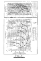
- the lower plot is the performance map which, as is well known, plots air flow rate through the compressor against the pressure ratio from the compressor inlet to outlet for a variety of impeller rotational speeds.
- the left hand line of the map represents the flow rates at which the compressor will surge for various turbocharger speeds and is known as the surge line.
- the compressor according to the present invention has a significantly improved surge margin, providing up to a 25% improvement on the surge margin of the conventional MWE compressor.
- the maximum flow (choke flow) is largely unaffected (shown by the right hand line of the map) as is the compressor efficiency (as shown by the upper plot of Figure 3 which plots the compressor efficiency as a function of air flow).
- the embodiment of the invention has a slightly increased pressure ratio capability compared to the conventional MWE compressor.
- the present invention relates to the length of the inlet and other aspects of the compressor and inlet structure may be entirely conventional. Moreover, the inlet need not be straight but could have one or more bends. Examples of embodiments of the present invention having curved inlet structures are illustrated in Figures 4a and 4b (which show the housing with impeller wheel omitted). In each case the inner and outer tubular walls 9 and 7 have extension portions 9a and 7a respectively which have axes that curve away from the axis 3 of the impeller (not shown). The two structures differ from each other only in the length and angle of curvature A of the curved portions 7a and 9a. With such embodiments the lengths L1 and L2 are measured along the axis of the tubular portions 7/7a and 9/9a which in these examples comprise both straight and curved portions. In other embodiments the lengths may be entirely curved.
- the diameter of the inner tubular wall may vary along its length.
- the value of D taken for determination of the lengths L1 and L2 is preferably the diameter of the downstream portion of the inner tubular wall.
- Compressors in accordance with the present invention may have many applications and in particular are suitable for incorporation in turbochargers.
Abstract
Description
- The present invention relates to a compressor. In particular, the invention relates to the inlet arrangement of a centrifugal compressor such as, for example, the compressor of a turbocharger.
- A compressor comprises an impeller wheel, carrying a plurality of blades (or vanes) mounted on a shaft for rotation within a compressor housing. Rotation of the impeller wheel causes gas (e.g. air) to be drawn into the impeller wheel and delivered to an outlet chamber or passage. In the case of a centrifugal compressor the outlet passage is in the form of a volute defined by the compressor housing around the impeller wheel and in the case of an axial compressor the gas is discharged axially.
- In a conventional turbocharger the impeller wheel is mounted to one end of a turbocharger shaft and is rotated by an exhaust driven turbine wheel mounted within a turbine housing at the other end of the turbocharger shaft. The shaft is mounted for rotation on bearing assemblies housed within a bearing housing positioned between the compressor and turbine housings.
- In some turbochargers the compressor inlet has a structure that has become known as a "a map width enhanced" (MWE) structure. An MWE structure is described for instance in US
patent number 4, 743,161. The inlet of such an MWE compressor comprises two coaxial tubular inlet sections, an outer inlet section or wall forming the compressor intake and inner inlet section wall defining the compressor inducer, or main inlet. The inner inlet section is shorter than the outer inlet section and has an inner surface which is an extension of a surface of an inner wall of the compressor housing which is swept by edges of the impeller wheel blades. The arrangement is such that an annular flow path is defined between the two tubular inlet sections which is open at its upstream end and which is provided with apertures at its downstream end which communicate with the inner surface of the compressor housing which faces the impeller wheel. - In operation, the pressure within the annular flow passage surrounding the compressor inducer is normally lower than atmospheric pressure and during high gas flow and high speed operation of the impeller wheel the pressure in the area swept by the impeller wheel is less than that in the annular passage. Thus, under such conditions air flows inward from the annular passage to the impeller wheel thereby increasing the amount of air reaching the impeller wheel, and increasing the maximum flow capacity of the compressor. However, as the flow through the impeller wheel drops, or as the speed of the impeller wheel drops, so the amount of air drawn into the impeller wheel through the annular passage decreases until equilibrium is reached. A further drop in the impeller wheel flow or speed results in the pressure in the area swept by the impeller wheel increasing above that within the annular passage and thus there is a reversal in the direction of air flow through the annular passage. That is, under such conditions air flows outward from the impeller wheel to the upstream end of the annular passage and is returned to the compressor intake for re-circulation. Increase in compressor gas flow or speed of the impeller wheel causes the reverse to happen, i.e. a decrease in the amount of air returned to the intake through the annular passage, followed by equilibrium, in turn followed by reversal of the air flow through the annular passage so that air is drawn in to the impeller wheel via the apertures communicating between the annular passage and the impeller.
- It is well known that this arrangement stabilises the performance of the compressor increasing the maximum flow capacity and improving the surge margin, i.e. decreasing the flow at which the compressor surges. This is known as increasing the width of the compressor "map", which is a plot of the compressor characteristic. All of this is well known to the skilled person.
- Compressor operation is extremely unstable under surge conditions due to large fluctuations in pressure and mass flow rate through the compressor. For many applications, such as in a turbocharger where the compressor supplies air to a reciprocating engine, these fluctuations in mass flow rate are unacceptable. As a result there is a continuing requirement to extend the useable flow range of compressors by improving the surge margin.
- It is therefore an object of the present invention to provide a compressor inlet structure which improves upon the surge margin of a conventional MWE compressor.
- According to the present invention there is provided a compressor for compressing a gas, the compressor comprising:
- a housing defining an inlet and an outlet;
- an impeller wheel including a plurality of vanes rotatably mounted within the housing;
- the housing having an inner wall defining a surface located in close proximity to radially outer edges of impeller vanes which sweep across said surface as the impeller wheel rotates about its axis; wherein the inlet comprises:
- an outer tubular wall extending away from the impeller wheel in an upstream direction and forming a gas intake portion of the inlet;
- an inner tubular wall of diameter D extending away from the impeller wheel in an upstream direction within the outer tubular wall and defining an inducer portion of the inlet;
- an annular gas flow passage defined between the inner and outer tubular walls and having an upstream end and a downstream end separated by a length L1 measured along its axis, the upstream end of the annular passage communicating with the intake or inducer portions of the inlet through at least one upstream aperture;
- at least one downstream aperture communicating between a downstream portion of the annular flow passage and said surface of the housing swept by the impeller vanes;
- the inner tubular wall extending upstream of said at least one downstream aperture by a length L2 measured along its axis;
-
- The present invention provides an improvement in surge margin by extending the length of the inner tubular wall/annular flow passage (with a conventional MWE compressor the dimensions L1/D and L2/D do not exceed 0.6 and 0.5 respectively). The most significant dimension is thought to be L2/D since this is effectively the length of the annular passage through which the air will flow at surge.
- Whereas much work has previously been carried out to optimise the location of the apertures communicating between the annular flow passage and the impeller wheel, the significance of the length of the flow passage/inducer portion of the inlet has not previously been appreciated. Indeed, compressors are often designed to be compact and occupy the smallest possible space so that the length of the inlet tends to be minimised. In addition conventional casting techniques used to manufacture compressor housings favour shorter inlet dimensions. In other words the prior art has generally been moving towards shortened inlet dimensions.
- Tests have shown that improvements are particularly significant when L1/D is greater than 0.9 and/or L2/D is greater than 0.97.
- The compressor according to the present invention is suited for inclusion in a turbocharger.
- Other preferred and advantageous features of the invention will be apparent from the following description.
- A specific embodiment of the present invention will now be described, with reference to the accompanying drawings, in which:
- Figure 1 is a cross-section of part of a conventional MWE compressor;
- Figure 2 is a cross-section through part of an MWE compressor modified in accordance with a first embodiment of the present invention;
- Figure 3 is an over-plot comparing the performance map of a conventional MWE compressor as illustrated in Figure 1 with the performance map of a compressor according to the present invention as illustrated in Figure 2; and
- Figures 4a and 4b illustrate two further embodiments of the present invention.
-
- Referring to Figure 1 the illustrated MWE compressor is a centrifugal compressor comprising an
impeller wheel 1 mounted within acompressor housing 2 on one end of a rotating shaft (not shown) which extends alongcompressor axis 3. Theimpeller wheel 1 has a plurality ofvanes 4 each of which has an outer edge 4a which sweeps across aninner housing surface 5 when theimpeller wheel 1 rotates about theaxis 3. Thecompressor housing 2 defines anoutlet volute 6 surrounding the impeller wheel, and an MWE inlet structure comprising an outertubular wall 7 extending outwardly upstream of theimpeller 1 and defining anintake 8 for gas such as air, and an innertubular wall 9 which extends part way in to theintake 8 and defines thecompressor inducer 10. The inner surface of theinner wall 9 is an upstream extension of thehousing wall surface 5 which is swept by the outside edges 4a of theimpeller blades 4. - An
annular flow passage 11 is defined around theinducer 10 between the inner andouter walls flow passage 11 is open to theintake portion 8 of the inlet at its upstream end and is closed at its downstream end by anannular wall 12 of thehousing 2, but communicates with theimpeller wheel 1 viaapertures 13 formed through the housing. Theapertures 13 communicate between a downstream portion of theannular flow passage 11 and theinner surface 5 of thehousing 2 which is swept by the outer edges 4a of theimpeller wheel blades 4. Theapertures 13 are typically defined by an annular slot bridged by circumferentially spaced web portions. There may for instance be four such web portions so that eachaperture 13 extends approximately 90° around theimpeller wheel 4. The apertures could however have other forms, for example comprising an annular array of relatively small diameter bores. - The
flow passage 11 thus has an overall axial length L1 defined between its upstream end (defined where thepassage 11 opens to inlet) and its downstream end (the axially innermost point of the passage 11). The annular passage also has an axial length L2 defined between its upstream end and the axial location of theapertures 13, which corresponds to the axial length of the portion of the inner tubular wall extending upstream of theapertures 13. - The conventional MWE compressor illustrated in Figure 1 operates as is described above in the introduction to this specification. In summary, when the flow rate through the compressor is high, air passes axially along the
annular flow path 11 towards theimpeller wheel 1, flowing to theimpeller wheel 1 through theapertures 13. When the flow through the compressor is low, the direction of air flow through theannular flow passage 11 is reversed so that air passes from the impeller wheel, through theapertures 13, and through theannular flow passage 11 in an upstream direction and is reintroduced into theair intake 8 for re-circulation through the compressor. This stabilises the performance of the compressor improving both the compressor surge margin and choke flow. - Figure 2 illustrates a modification of the conventional MWE compressor of Figure 1 in accordance with a first embodiment of the present invention. Components which correspond to those of the compressor of Figure 1 are identified by the same reference numerals as used in Figure 1. Thus, it will be seen that the illustrated compressor in accordance with the present invention is identical to the conventional MWE compressor of Figure 1 except that the axial length of the inlet is extended.
- Referring to Figure 2 in more detail, the inner
tubular wall 9 extends upstream of the compressor to greater extent than is conventional, and the length of the outertubular wall 7 is similarly extended to accommodate the longerinner wall 9. Thus the overall axial length L1 of theannular flow passage 11 is extended, as is the length L2. Specifically, the present inventors have found that extending the length of the annular passage to the extent that L1/D > 0.65 and/or L2/D > 0.6, where D is the internal diameter of the inner tubular wall, greatly increases the surge margin of the compressor. - The improvement in performance provided by the present invention is illustrated by Figure 3 which is an over-plot of the performance of a compressor according to the present invention (shown in dotted lines), with L1/D = 1.41 and L2/D = 1.33, in comparison with the performance of a conventional MWE compressor (shown in solid lines) with L1/D = 0.35. The lower plot is the performance map which, as is well known, plots air flow rate through the compressor against the pressure ratio from the compressor inlet to outlet for a variety of impeller rotational speeds. The left hand line of the map represents the flow rates at which the compressor will surge for various turbocharger speeds and is known as the surge line. It can be seen the compressor according to the present invention has a significantly improved surge margin, providing up to a 25% improvement on the surge margin of the conventional MWE compressor. The maximum flow (choke flow) is largely unaffected (shown by the right hand line of the map) as is the compressor efficiency (as shown by the upper plot of Figure 3 which plots the compressor efficiency as a function of air flow). It can however be seen that the embodiment of the invention has a slightly increased pressure ratio capability compared to the conventional MWE compressor.
- The present invention relates to the length of the inlet and other aspects of the compressor and inlet structure may be entirely conventional. Moreover, the inlet need not be straight but could have one or more bends. Examples of embodiments of the present invention having curved inlet structures are illustrated in Figures 4a and 4b (which show the housing with impeller wheel omitted). In each case the inner and outer
tubular walls extension portions axis 3 of the impeller (not shown). The two structures differ from each other only in the length and angle of curvature A of thecurved portions tubular portions 7/7a and 9/9a which in these examples comprise both straight and curved portions. In other embodiments the lengths may be entirely curved. - In some embodiments the diameter of the inner tubular wall may vary along its length. In this instance, the value of D taken for determination of the lengths L1 and L2 is preferably the diameter of the downstream portion of the inner tubular wall.
- Other possible modifications to the embodiments of the invention described above will be readily apparent to the appropriately skilled person.
- Compressors in accordance with the present invention may have many applications and in particular are suitable for incorporation in turbochargers.
Claims (11)
- A compressor for compressing a gas, the compressor comprising:wherein the inlet comprises:a housing defining an inlet and an outlet;an impeller wheel including a plurality of vanes rotatably mounted within the housing;the housing having an inner wall defining a surface located in close proximity to radially outer edges of impeller vanes which sweep across said surface as the impeller wheel rotates about its axis;wherein L1/D > 0.65 and/or L2/D > 0.6.an outer tubular wall extending away from the impeller wheel in an upstream direction and forming a gas intake portion of the inlet;an inner tubular wall of diameter D extending away from the impeller wheel in an upstream direction within the outer tubular wall and defining an inducer portion of the inlet;an annular gas flow passage defined between the inner and outer tubular walls and having an upstream end and a downstream end separated by a length L1 measured along its axis, the upstream end of the annular passage communicating with the intake or inducer portions of the inlet through at least one upstream aperture;at least one downstream aperture communicating between a downstream portion of the annular flow passage and said surface of the housing swept by the impeller vanes;the inner tubular wall extending upstream of said at least one downstream aperture by a length L2 measured along its axis;
- A compressor according to claim 1, wherein L1/D> 0.9 and/or L2/D> 0.97
- A compressor according to claim 1 or claim 2, wherein the annular flow passage is open at its upstream end, such that said at least one upstream aperture is an annular opening defined at the upstream end of the inner tubular wall between the inner and outer tubular walls.
- A compressor according to any preceding claim, wherein the inner tubular wall and the annular passage wall are co-axial having an axis which is a continuation of the impeller wheel axis.
- A compressor according to any preceding claim, wherein the lengths L1 and L2 are entirely straight.
- A compressor according to any one of claims 1 to 4, wherein the lengths L1 and L2 are at least in part curved.
- A compressor according to any preceding claim, wherein said diameter D is constant along substantially the entire length L2 of the inner tubular wall.
- A compressor according to any on of claims 1 to 7, wherein said diameter D is the minimum diameter of the inner tubular wall along its length L2.
- A compressor according to any one of claims 1 to 7, wherein said diameter D is the maximum diameter of the inner tubular wall along its length L2.
- A compressor according to any one of claims 1 to 7, wherein the diameter D is the average diameter of the inner tubular wall along its length L2.
- A turbocharger comprising a compressor, wherein the compressor comprises:wherein the inlet comprises:a housing defining an inlet and an outlet;an impeller wheel including a plurality of vanes rotatably mounted within the housing;the housing having an inner wall defining a surface located in close proximity to radially outer edges of impeller vanes which sweep across said surface as the impeller wheel rotates about its axis;wherein L1/D > 0.65 and/or L2/D > 0.6.an outer tubular wall extending away from the impeller wheel in an upstream direction and forming a gas intake portion of the inlet;an inner tubular wall of diameter D extending away from the impeller wheel in an upstream direction within the outer tubular wall and defining an inducer portion of the inlet;an annular gas flow passage defined between the inner and outer tubular walls and having an upstream end and a downstream end separated by a length L1 measured along its axis, the upstream end of the annular passage communicating with the intake or inducer portions of the inlet through at least one upstream aperture;at least one downstream aperture communicating between a downstream portion of the annular flow passage and said surface of the housing swept by the impeller vanes;the inner tubular wall extending upstream of said at least one downstream aperture by a length L2 measured along its axis;
Applications Claiming Priority (2)
| Application Number | Priority Date | Filing Date | Title |
|---|---|---|---|
| GB0309892 | 2003-04-30 | ||
| GB0309892 | 2003-04-30 |
Publications (3)
| Publication Number | Publication Date |
|---|---|
| EP1473465A1 true EP1473465A1 (en) | 2004-11-03 |
| EP1473465B1 EP1473465B1 (en) | 2015-01-14 |
| EP1473465B2 EP1473465B2 (en) | 2018-08-01 |
Family
ID=32982444
Family Applications (1)
| Application Number | Title | Priority Date | Filing Date |
|---|---|---|---|
| EP04251692.2A Expired - Lifetime EP1473465B2 (en) | 2003-04-30 | 2004-03-24 | Compressor |
Country Status (5)
| Country | Link |
|---|---|
| US (1) | US7229243B2 (en) |
| EP (1) | EP1473465B2 (en) |
| JP (1) | JP2004332734A (en) |
| KR (1) | KR101178213B1 (en) |
| CN (1) | CN100394038C (en) |
Cited By (6)
| Publication number | Priority date | Publication date | Assignee | Title |
|---|---|---|---|---|
| WO2007078667A1 (en) * | 2005-12-15 | 2007-07-12 | Honeywell International Inc. | Ported shroud with filtered external ventilation |
| FR2904375A1 (en) * | 2006-07-26 | 2008-02-01 | Renault Sas | Air intake device for turbo-compressor of air supercharged oil engine, has buffer volume with passage section larger than that of upstream section of duct to create boundary of surface of passage section by considering air flow direction |
| WO2008087432A1 (en) * | 2007-01-19 | 2008-07-24 | Cummins Turbo Technologies Limited | Compressor |
| WO2011082942A3 (en) * | 2009-12-16 | 2011-12-01 | Piller Industrieventilatoren Gmbh | Turbo compressor |
| WO2017160200A1 (en) | 2016-03-17 | 2017-09-21 | Scania Cv Ab | A compressor arrangement supplying charged air to a combustion engine |
| WO2021096920A1 (en) * | 2019-11-12 | 2021-05-20 | Fca Us Llc | Bifurcated air induction system for turbocharged engines |
Families Citing this family (38)
| Publication number | Priority date | Publication date | Assignee | Title |
|---|---|---|---|---|
| DE602004019986D1 (en) * | 2004-06-15 | 2009-04-23 | Honeywell Int Inc | COMPRISED WITH A COMPRESSOR HOUSING SILENCER |
| US7407364B2 (en) * | 2005-03-01 | 2008-08-05 | Honeywell International, Inc. | Turbocharger compressor having ported second-stage shroud, and associated method |
| KR101184465B1 (en) | 2005-12-20 | 2012-09-19 | 두산인프라코어 주식회사 | Turbo-Charger for compress a Blow-by Gas of an engine |
| US7698894B2 (en) * | 2006-05-22 | 2010-04-20 | International Engine Intellectual Property Company, Llc | Engine intake air compressor and method |
| US8857053B2 (en) * | 2007-08-29 | 2014-10-14 | Caterpillar Inc. | Compressor housing remanufacturing method and apparatus |
| GB0718846D0 (en) * | 2007-09-27 | 2007-11-07 | Cummins Turbo Tech Ltd | Compressor |
| AU2009291507B2 (en) * | 2008-09-11 | 2013-06-13 | Hunter Pacific International Pty Ltd | Extraction fan and rotor |
| US8210794B2 (en) * | 2008-10-30 | 2012-07-03 | Honeywell International Inc. | Axial-centrifugal compressor with ported shroud |
| KR20110091528A (en) * | 2008-11-18 | 2011-08-11 | 보르그워너 인코퍼레이티드 | Compressor of an exhaust-gas turbocharger |
| DE102009052162B4 (en) * | 2009-11-06 | 2016-04-14 | Mtu Friedrichshafen Gmbh | Compressor arrangement and method for producing such |
| US9816522B2 (en) | 2010-02-09 | 2017-11-14 | Ihi Corporation | Centrifugal compressor having an asymmetric self-recirculating casing treatment |
| JP5430683B2 (en) * | 2010-02-09 | 2014-03-05 | 株式会社Ihi | Centrifugal compressor with non-axisymmetric self-circulating casing treatment |
| JP5430685B2 (en) | 2010-02-09 | 2014-03-05 | 株式会社Ihi | Centrifugal compressor with non-axisymmetric self-circulating casing treatment |
| WO2011099417A1 (en) * | 2010-02-09 | 2011-08-18 | 株式会社Ihi | Centrifugal compressor using an asymmetric self-recirculating casing treatment |
| CN102892995B (en) * | 2010-06-04 | 2015-11-25 | 博格华纳公司 | The compressor of exhaust turbine supercharger |
| US9091232B2 (en) | 2010-09-02 | 2015-07-28 | Borgwarner Inc. | Compressor recirculation into annular volume |
| JP5895343B2 (en) * | 2011-01-24 | 2016-03-30 | 株式会社Ihi | Centrifugal compressor and method for manufacturing centrifugal compressor |
| JP5948892B2 (en) | 2012-01-23 | 2016-07-06 | 株式会社Ihi | Centrifugal compressor |
| JP5853721B2 (en) | 2012-01-23 | 2016-02-09 | 株式会社Ihi | Centrifugal compressor |
| JP2014198999A (en) | 2012-02-23 | 2014-10-23 | 三菱重工業株式会社 | Compressor |
| JP5920127B2 (en) * | 2012-09-06 | 2016-05-18 | トヨタ自動車株式会社 | Supercharger deposit remover |
| CN102927060B (en) * | 2012-11-02 | 2015-12-02 | 江苏大学 | A kind of suction port improving cavitation performance of centrifugal pump |
| US9726185B2 (en) | 2013-05-14 | 2017-08-08 | Honeywell International Inc. | Centrifugal compressor with casing treatment for surge control |
| US10107296B2 (en) * | 2013-06-25 | 2018-10-23 | Ford Global Technologies, Llc | Turbocharger systems and method to prevent compressor choke |
| WO2015013100A1 (en) * | 2013-07-24 | 2015-01-29 | Borgwarner Inc. | Turbocharger combining axial flow turbine with a compressor stage utilizing active casing treatment |
| CN104019058B (en) * | 2014-06-27 | 2016-03-09 | 哈尔滨工程大学 | The centrifugal-flow compressor casing bleed recirculation structure of variable geometry |
| US10267214B2 (en) | 2014-09-29 | 2019-04-23 | Progress Rail Locomotive Inc. | Compressor inlet recirculation system for a turbocharger |
| US9719518B2 (en) * | 2014-11-10 | 2017-08-01 | Honeywell International Inc. | Adjustable-trim centrifugal compressor with ported shroud, and turbocharger having same |
| US10648702B2 (en) * | 2015-08-11 | 2020-05-12 | Carrier Corporation | Low capacity, low-GWP, HVAC system |
| CN109563778A (en) * | 2016-06-22 | 2019-04-02 | 史蒂文·顿·阿诺德 | Improved entrance system for radial-flow compressor |
| US10436211B2 (en) * | 2016-08-15 | 2019-10-08 | Borgwarner Inc. | Compressor wheel, method of making the same, and turbocharger including the same |
| CN110520630B (en) * | 2017-04-25 | 2021-06-25 | 株式会社Ihi | Centrifugal compressor |
| US10309417B2 (en) | 2017-05-12 | 2019-06-04 | Borgwarner Inc. | Turbocharger having improved ported shroud compressor housing |
| US10316859B2 (en) | 2017-05-12 | 2019-06-11 | Borgwarner Inc. | Turbocharger having improved ported shroud compressor housing |
| DE102017110642A1 (en) * | 2017-05-16 | 2018-11-22 | Ebm-Papst Mulfingen Gmbh & Co. Kg | Blower arrangement with flow dividing nozzle |
| CN110185631A (en) * | 2019-04-18 | 2019-08-30 | 西安热工研究院有限公司 | The symmetrical overcritical working medium closed centrifugal compressor set of partial admission and method |
| CN112628161A (en) * | 2020-11-18 | 2021-04-09 | 靳普 | Air-cooled compressor |
| CN112503004A (en) * | 2020-11-18 | 2021-03-16 | 靳普 | Back-to-back type compressor |
Citations (3)
| Publication number | Priority date | Publication date | Assignee | Title |
|---|---|---|---|---|
| US4743161A (en) * | 1985-12-24 | 1988-05-10 | Holset Engineering Company Limited | Compressors |
| EP0547535A1 (en) * | 1991-12-14 | 1993-06-23 | Alcatel SEL Aktiengesellschaft | Radial fan for the delivery of a combustible gas mixture |
| GB2319809A (en) * | 1996-10-12 | 1998-06-03 | Holset Engineering Co | An enhanced map width compressor |
Family Cites Families (15)
| Publication number | Priority date | Publication date | Assignee | Title |
|---|---|---|---|---|
| US3504986A (en) † | 1968-03-12 | 1970-04-07 | Bendix Corp | Wide range inducer |
| US4375937A (en) † | 1981-01-28 | 1983-03-08 | Ingersoll-Rand Company | Roto-dynamic pump with a backflow recirculator |
| US4834611A (en) * | 1984-06-25 | 1989-05-30 | Rockwell International Corporation | Vortex proof shrouded inducer |
| CH675279A5 (en) * | 1988-06-29 | 1990-09-14 | Asea Brown Boveri | |
| US4930978A (en) * | 1988-07-01 | 1990-06-05 | Household Manufacturing, Inc. | Compressor stage with multiple vented inducer shroud |
| DE4027174A1 (en) * | 1990-08-28 | 1992-03-05 | Kuehnle Kopp Kausch Ag | MAP STABILIZATION WITH A RADIAL COMPRESSOR |
| US5246335A (en) * | 1991-05-01 | 1993-09-21 | Ishikawajima-Harimas Jukogyo Kabushiki Kaisha | Compressor casing for turbocharger and assembly thereof |
| JP3038398B2 (en) * | 1991-09-02 | 2000-05-08 | 石川島播磨重工業株式会社 | Centrifugal compressor |
| US5304033A (en) * | 1992-07-20 | 1994-04-19 | Allied-Signal Inc. | Rotary compressor with stepped cover contour |
| US5295785A (en) † | 1992-12-23 | 1994-03-22 | Caterpillar Inc. | Turbocharger having reduced noise emissions |
| GB9918072D0 (en) † | 1999-07-30 | 1999-10-06 | Alliedsignal Ltd | Turbocharger |
| US6623239B2 (en) * | 2000-12-13 | 2003-09-23 | Honeywell International Inc. | Turbocharger noise deflector |
| DE10105456A1 (en) * | 2001-02-07 | 2002-08-08 | Daimler Chrysler Ag | Compressors, in particular for an internal combustion engine |
| DE602004001908T2 (en) * | 2003-04-30 | 2007-04-26 | Holset Engineering Co. Ltd., Huddersfield | compressor |
| US6945748B2 (en) * | 2004-01-22 | 2005-09-20 | Electro-Motive Diesel, Inc. | Centrifugal compressor with channel ring defined inlet recirculation channel |
-
2004
- 2004-03-24 EP EP04251692.2A patent/EP1473465B2/en not_active Expired - Lifetime
- 2004-04-06 US US10/818,640 patent/US7229243B2/en active Active
- 2004-04-28 KR KR1020040029333A patent/KR101178213B1/en active IP Right Grant
- 2004-04-30 CN CNB2004100434280A patent/CN100394038C/en not_active Expired - Lifetime
- 2004-04-30 JP JP2004135795A patent/JP2004332734A/en active Pending
Patent Citations (3)
| Publication number | Priority date | Publication date | Assignee | Title |
|---|---|---|---|---|
| US4743161A (en) * | 1985-12-24 | 1988-05-10 | Holset Engineering Company Limited | Compressors |
| EP0547535A1 (en) * | 1991-12-14 | 1993-06-23 | Alcatel SEL Aktiengesellschaft | Radial fan for the delivery of a combustible gas mixture |
| GB2319809A (en) * | 1996-10-12 | 1998-06-03 | Holset Engineering Co | An enhanced map width compressor |
Cited By (14)
| Publication number | Priority date | Publication date | Assignee | Title |
|---|---|---|---|---|
| US8511083B2 (en) | 2005-12-15 | 2013-08-20 | Honeywell International, Inc. | Ported shroud with filtered external ventilation |
| WO2007078667A1 (en) * | 2005-12-15 | 2007-07-12 | Honeywell International Inc. | Ported shroud with filtered external ventilation |
| FR2904375A1 (en) * | 2006-07-26 | 2008-02-01 | Renault Sas | Air intake device for turbo-compressor of air supercharged oil engine, has buffer volume with passage section larger than that of upstream section of duct to create boundary of surface of passage section by considering air flow direction |
| WO2008087432A1 (en) * | 2007-01-19 | 2008-07-24 | Cummins Turbo Technologies Limited | Compressor |
| US8256218B2 (en) | 2007-01-19 | 2012-09-04 | Cummins Turbo Technologies Limited | Compressor |
| US8820073B2 (en) | 2007-01-19 | 2014-09-02 | Cummins Turbo Technologies Limited | Compressor |
| CN101663489B (en) * | 2007-01-19 | 2013-03-13 | 康明斯涡轮增压技术有限公司 | Compressor |
| WO2011082942A3 (en) * | 2009-12-16 | 2011-12-01 | Piller Industrieventilatoren Gmbh | Turbo compressor |
| CN102695881A (en) * | 2009-12-16 | 2012-09-26 | 德国琵乐风机公司 | Turbo compressor |
| US8926264B2 (en) | 2009-12-16 | 2015-01-06 | Piller Industrieventilatoren Gmbh | Turbo compressor having a flow diversion channel |
| CN102695881B (en) * | 2009-12-16 | 2016-03-09 | 琵乐鼓风机压缩机有限责任公司 | Turbocompressor |
| WO2017160200A1 (en) | 2016-03-17 | 2017-09-21 | Scania Cv Ab | A compressor arrangement supplying charged air to a combustion engine |
| EP3430269A4 (en) * | 2016-03-17 | 2019-11-13 | Scania CV AB | A compressor arrangement supplying charged air to a combustion engine |
| WO2021096920A1 (en) * | 2019-11-12 | 2021-05-20 | Fca Us Llc | Bifurcated air induction system for turbocharged engines |
Also Published As
| Publication number | Publication date |
|---|---|
| US20050008484A1 (en) | 2005-01-13 |
| EP1473465B2 (en) | 2018-08-01 |
| CN100394038C (en) | 2008-06-11 |
| JP2004332734A (en) | 2004-11-25 |
| CN1542289A (en) | 2004-11-03 |
| KR20040094329A (en) | 2004-11-09 |
| EP1473465B1 (en) | 2015-01-14 |
| US7229243B2 (en) | 2007-06-12 |
| KR101178213B1 (en) | 2012-08-29 |
Similar Documents
| Publication | Publication Date | Title |
|---|---|---|
| EP1473465B1 (en) | Compressor | |
| EP1473463B1 (en) | Compressor | |
| EP1566549B1 (en) | Compressor | |
| EP2024643B1 (en) | Inclined rib ported shroud compressor housing | |
| JP2004332734A5 (en) | ||
| US5228832A (en) | Mixed flow compressor | |
| US20190264710A1 (en) | Turbocharger compressor having adjustable trim mechanism including vortex reducers | |
| US7575412B2 (en) | Anti-stall casing treatment for turbo compressors | |
| US9874224B2 (en) | Centrifugal compressor and turbocharger | |
| US11808283B2 (en) | Turbocharger having adjustable-trim centrifugal compressor including air inlet wall having cavities for suppression of noise and flow fluctuations | |
| JP2019007425A (en) | Centrifugal compressor and turbocharger | |
| CN106662119B (en) | Improved scroll for a turbomachine, turbomachine comprising said scroll and method of operation | |
| CN109563839A (en) | Centrifugal compressor with the diffuser with throat | |
| JP7463498B2 (en) | Concentric introduction of wastegate mass flow into a flow-optimized axial diffuser | |
| JP7123029B2 (en) | centrifugal compressor | |
| US7942626B2 (en) | Compressor |
Legal Events
| Date | Code | Title | Description |
|---|---|---|---|
| PUAI | Public reference made under article 153(3) epc to a published international application that has entered the european phase |
Free format text: ORIGINAL CODE: 0009012 |
|
| AK | Designated contracting states |
Kind code of ref document: A1 Designated state(s): AT BE BG CH CY CZ DE DK EE ES FI FR GB GR HU IE IT LI LU MC NL PL PT RO SE SI SK TR |
|
| AX | Request for extension of the european patent |
Extension state: AL HR LT LV MK |
|
| 17P | Request for examination filed |
Effective date: 20050322 |
|
| AKX | Designation fees paid |
Designated state(s): DE FR GB |
|
| 17Q | First examination report despatched |
Effective date: 20080825 |
|
| GRAP | Despatch of communication of intention to grant a patent |
Free format text: ORIGINAL CODE: EPIDOSNIGR1 |
|
| INTG | Intention to grant announced |
Effective date: 20140730 |
|
| GRAS | Grant fee paid |
Free format text: ORIGINAL CODE: EPIDOSNIGR3 |
|
| GRAA | (expected) grant |
Free format text: ORIGINAL CODE: 0009210 |
|
| AK | Designated contracting states |
Kind code of ref document: B1 Designated state(s): DE FR GB |
|
| REG | Reference to a national code |
Ref country code: GB Ref legal event code: FG4D |
|
| REG | Reference to a national code |
Ref country code: DE Ref legal event code: R096 Ref document number: 602004046499 Country of ref document: DE Effective date: 20150226 |
|
| REG | Reference to a national code |
Ref country code: FR Ref legal event code: PLFP Year of fee payment: 12 |
|
| REG | Reference to a national code |
Ref country code: DE Ref legal event code: R026 Ref document number: 602004046499 Country of ref document: DE |
|
| PLBI | Opposition filed |
Free format text: ORIGINAL CODE: 0009260 |
|
| 26 | Opposition filed |
Opponent name: BOSCH MAHLE TURBO SYSTEMS GMBH & CO. KG Effective date: 20151013 |
|
| PLAX | Notice of opposition and request to file observation + time limit sent |
Free format text: ORIGINAL CODE: EPIDOSNOBS2 |
|
| PLAF | Information modified related to communication of a notice of opposition and request to file observations + time limit |
Free format text: ORIGINAL CODE: EPIDOSCOBS2 |
|
| REG | Reference to a national code |
Ref country code: FR Ref legal event code: PLFP Year of fee payment: 13 |
|
| PLBB | Reply of patent proprietor to notice(s) of opposition received |
Free format text: ORIGINAL CODE: EPIDOSNOBS3 |
|
| REG | Reference to a national code |
Ref country code: FR Ref legal event code: PLFP Year of fee payment: 14 |
|
| REG | Reference to a national code |
Ref country code: FR Ref legal event code: PLFP Year of fee payment: 15 |
|
| PUAH | Patent maintained in amended form |
Free format text: ORIGINAL CODE: 0009272 |
|
| STAA | Information on the status of an ep patent application or granted ep patent |
Free format text: STATUS: PATENT MAINTAINED AS AMENDED |
|
| 27A | Patent maintained in amended form |
Effective date: 20180801 |
|
| AK | Designated contracting states |
Kind code of ref document: B2 Designated state(s): DE FR GB |
|
| REG | Reference to a national code |
Ref country code: DE Ref legal event code: R102 Ref document number: 602004046499 Country of ref document: DE |
|
| PGFP | Annual fee paid to national office [announced via postgrant information from national office to epo] |
Ref country code: FR Payment date: 20230327 Year of fee payment: 20 |
|
| PGFP | Annual fee paid to national office [announced via postgrant information from national office to epo] |
Ref country code: GB Payment date: 20230327 Year of fee payment: 20 Ref country code: DE Payment date: 20230329 Year of fee payment: 20 |
|
| P01 | Opt-out of the competence of the unified patent court (upc) registered |
Effective date: 20230510 |
|
| REG | Reference to a national code |
Ref country code: DE Ref legal event code: R071 Ref document number: 602004046499 Country of ref document: DE |
|
| REG | Reference to a national code |
Ref country code: GB Ref legal event code: PE20 Expiry date: 20240323 |