EP1473142A1 - Verfahren zum Ausgleichen eines Fügespaltes - Google Patents
Verfahren zum Ausgleichen eines Fügespaltes Download PDFInfo
- Publication number
- EP1473142A1 EP1473142A1 EP04009488A EP04009488A EP1473142A1 EP 1473142 A1 EP1473142 A1 EP 1473142A1 EP 04009488 A EP04009488 A EP 04009488A EP 04009488 A EP04009488 A EP 04009488A EP 1473142 A1 EP1473142 A1 EP 1473142A1
- Authority
- EP
- European Patent Office
- Prior art keywords
- distance
- shell
- surface area
- gap
- area
- Prior art date
- Legal status (The legal status is an assumption and is not a legal conclusion. Google has not performed a legal analysis and makes no representation as to the accuracy of the status listed.)
- Granted
Links
- 238000005304 joining Methods 0.000 title claims description 56
- 238000000034 method Methods 0.000 title claims description 45
- 239000000463 material Substances 0.000 claims abstract description 39
- 239000000945 filler Substances 0.000 claims abstract description 11
- 229910052751 metal Inorganic materials 0.000 claims abstract description 8
- 239000002184 metal Substances 0.000 claims abstract description 8
- 239000004033 plastic Substances 0.000 claims abstract description 7
- 229920003023 plastic Polymers 0.000 claims abstract description 7
- 238000005094 computer simulation Methods 0.000 claims description 9
- 239000004918 carbon fiber reinforced polymer Substances 0.000 claims description 4
- 238000006243 chemical reaction Methods 0.000 claims description 4
- 229910052782 aluminium Inorganic materials 0.000 claims description 3
- XAGFODPZIPBFFR-UHFFFAOYSA-N aluminium Chemical compound [Al] XAGFODPZIPBFFR-UHFFFAOYSA-N 0.000 claims description 3
- 235000011837 pasties Nutrition 0.000 claims description 3
- 239000011347 resin Substances 0.000 claims description 2
- 229920005989 resin Polymers 0.000 claims description 2
- 238000004364 calculation method Methods 0.000 claims 1
- 230000003028 elevating effect Effects 0.000 claims 1
- 239000007769 metal material Substances 0.000 claims 1
- 239000000843 powder Substances 0.000 abstract 1
- 230000003014 reinforcing effect Effects 0.000 abstract 1
- 238000005516 engineering process Methods 0.000 description 10
- 238000011156 evaluation Methods 0.000 description 6
- 238000012545 processing Methods 0.000 description 5
- 238000004519 manufacturing process Methods 0.000 description 4
- 239000000853 adhesive Substances 0.000 description 3
- 230000001070 adhesive effect Effects 0.000 description 3
- 230000000284 resting effect Effects 0.000 description 3
- 229910000838 Al alloy Inorganic materials 0.000 description 2
- 229920000049 Carbon (fiber) Polymers 0.000 description 2
- 239000004917 carbon fiber Substances 0.000 description 2
- 238000001514 detection method Methods 0.000 description 2
- 238000011161 development Methods 0.000 description 2
- 230000018109 developmental process Effects 0.000 description 2
- 238000003825 pressing Methods 0.000 description 2
- 230000002787 reinforcement Effects 0.000 description 2
- 238000012546 transfer Methods 0.000 description 2
- 229920002430 Fibre-reinforced plastic Polymers 0.000 description 1
- 102100025490 Slit homolog 1 protein Human genes 0.000 description 1
- 101710123186 Slit homolog 1 protein Proteins 0.000 description 1
- 238000009825 accumulation Methods 0.000 description 1
- 230000000295 complement effect Effects 0.000 description 1
- 239000012141 concentrate Substances 0.000 description 1
- 238000010276 construction Methods 0.000 description 1
- 239000011151 fibre-reinforced plastic Substances 0.000 description 1
- -1 for example Inorganic materials 0.000 description 1
- 239000003292 glue Substances 0.000 description 1
- 238000011835 investigation Methods 0.000 description 1
- VNWKTOKETHGBQD-UHFFFAOYSA-N methane Chemical compound C VNWKTOKETHGBQD-UHFFFAOYSA-N 0.000 description 1
- 230000006855 networking Effects 0.000 description 1
- 238000002360 preparation method Methods 0.000 description 1
- 238000005070 sampling Methods 0.000 description 1
- 239000007787 solid Substances 0.000 description 1
- 238000003860 storage Methods 0.000 description 1
- 238000013517 stratification Methods 0.000 description 1
- 238000003466 welding Methods 0.000 description 1
Images


Classifications
-
- B—PERFORMING OPERATIONS; TRANSPORTING
- B29—WORKING OF PLASTICS; WORKING OF SUBSTANCES IN A PLASTIC STATE IN GENERAL
- B29C—SHAPING OR JOINING OF PLASTICS; SHAPING OF MATERIAL IN A PLASTIC STATE, NOT OTHERWISE PROVIDED FOR; AFTER-TREATMENT OF THE SHAPED PRODUCTS, e.g. REPAIRING
- B29C65/00—Joining or sealing of preformed parts, e.g. welding of plastics materials; Apparatus therefor
- B29C65/48—Joining or sealing of preformed parts, e.g. welding of plastics materials; Apparatus therefor using adhesives, i.e. using supplementary joining material; solvent bonding
- B29C65/50—Joining or sealing of preformed parts, e.g. welding of plastics materials; Apparatus therefor using adhesives, i.e. using supplementary joining material; solvent bonding using adhesive tape, e.g. thermoplastic tape; using threads or the like
- B29C65/5057—Joining or sealing of preformed parts, e.g. welding of plastics materials; Apparatus therefor using adhesives, i.e. using supplementary joining material; solvent bonding using adhesive tape, e.g. thermoplastic tape; using threads or the like positioned between the surfaces to be joined
-
- B—PERFORMING OPERATIONS; TRANSPORTING
- B29—WORKING OF PLASTICS; WORKING OF SUBSTANCES IN A PLASTIC STATE IN GENERAL
- B29C—SHAPING OR JOINING OF PLASTICS; SHAPING OF MATERIAL IN A PLASTIC STATE, NOT OTHERWISE PROVIDED FOR; AFTER-TREATMENT OF THE SHAPED PRODUCTS, e.g. REPAIRING
- B29C65/00—Joining or sealing of preformed parts, e.g. welding of plastics materials; Apparatus therefor
- B29C65/48—Joining or sealing of preformed parts, e.g. welding of plastics materials; Apparatus therefor using adhesives, i.e. using supplementary joining material; solvent bonding
- B29C65/50—Joining or sealing of preformed parts, e.g. welding of plastics materials; Apparatus therefor using adhesives, i.e. using supplementary joining material; solvent bonding using adhesive tape, e.g. thermoplastic tape; using threads or the like
- B29C65/5064—Joining or sealing of preformed parts, e.g. welding of plastics materials; Apparatus therefor using adhesives, i.e. using supplementary joining material; solvent bonding using adhesive tape, e.g. thermoplastic tape; using threads or the like of particular form, e.g. being C-shaped, T-shaped
- B29C65/5078—Joining or sealing of preformed parts, e.g. welding of plastics materials; Apparatus therefor using adhesives, i.e. using supplementary joining material; solvent bonding using adhesive tape, e.g. thermoplastic tape; using threads or the like of particular form, e.g. being C-shaped, T-shaped and being composed by several elements
-
- B—PERFORMING OPERATIONS; TRANSPORTING
- B29—WORKING OF PLASTICS; WORKING OF SUBSTANCES IN A PLASTIC STATE IN GENERAL
- B29C—SHAPING OR JOINING OF PLASTICS; SHAPING OF MATERIAL IN A PLASTIC STATE, NOT OTHERWISE PROVIDED FOR; AFTER-TREATMENT OF THE SHAPED PRODUCTS, e.g. REPAIRING
- B29C65/00—Joining or sealing of preformed parts, e.g. welding of plastics materials; Apparatus therefor
- B29C65/48—Joining or sealing of preformed parts, e.g. welding of plastics materials; Apparatus therefor using adhesives, i.e. using supplementary joining material; solvent bonding
- B29C65/52—Joining or sealing of preformed parts, e.g. welding of plastics materials; Apparatus therefor using adhesives, i.e. using supplementary joining material; solvent bonding characterised by the way of applying the adhesive
-
- B—PERFORMING OPERATIONS; TRANSPORTING
- B29—WORKING OF PLASTICS; WORKING OF SUBSTANCES IN A PLASTIC STATE IN GENERAL
- B29C—SHAPING OR JOINING OF PLASTICS; SHAPING OF MATERIAL IN A PLASTIC STATE, NOT OTHERWISE PROVIDED FOR; AFTER-TREATMENT OF THE SHAPED PRODUCTS, e.g. REPAIRING
- B29C66/00—General aspects of processes or apparatus for joining preformed parts
- B29C66/01—General aspects dealing with the joint area or with the area to be joined
- B29C66/02—Preparation of the material, in the area to be joined, prior to joining or welding
-
- B—PERFORMING OPERATIONS; TRANSPORTING
- B29—WORKING OF PLASTICS; WORKING OF SUBSTANCES IN A PLASTIC STATE IN GENERAL
- B29C—SHAPING OR JOINING OF PLASTICS; SHAPING OF MATERIAL IN A PLASTIC STATE, NOT OTHERWISE PROVIDED FOR; AFTER-TREATMENT OF THE SHAPED PRODUCTS, e.g. REPAIRING
- B29C66/00—General aspects of processes or apparatus for joining preformed parts
- B29C66/01—General aspects dealing with the joint area or with the area to be joined
- B29C66/05—Particular design of joint configurations
- B29C66/10—Particular design of joint configurations particular design of the joint cross-sections
- B29C66/11—Joint cross-sections comprising a single joint-segment, i.e. one of the parts to be joined comprising a single joint-segment in the joint cross-section
- B29C66/112—Single lapped joints
-
- B—PERFORMING OPERATIONS; TRANSPORTING
- B29—WORKING OF PLASTICS; WORKING OF SUBSTANCES IN A PLASTIC STATE IN GENERAL
- B29C—SHAPING OR JOINING OF PLASTICS; SHAPING OF MATERIAL IN A PLASTIC STATE, NOT OTHERWISE PROVIDED FOR; AFTER-TREATMENT OF THE SHAPED PRODUCTS, e.g. REPAIRING
- B29C66/00—General aspects of processes or apparatus for joining preformed parts
- B29C66/01—General aspects dealing with the joint area or with the area to be joined
- B29C66/05—Particular design of joint configurations
- B29C66/10—Particular design of joint configurations particular design of the joint cross-sections
- B29C66/11—Joint cross-sections comprising a single joint-segment, i.e. one of the parts to be joined comprising a single joint-segment in the joint cross-section
- B29C66/112—Single lapped joints
- B29C66/1122—Single lap to lap joints, i.e. overlap joints
-
- B—PERFORMING OPERATIONS; TRANSPORTING
- B29—WORKING OF PLASTICS; WORKING OF SUBSTANCES IN A PLASTIC STATE IN GENERAL
- B29C—SHAPING OR JOINING OF PLASTICS; SHAPING OF MATERIAL IN A PLASTIC STATE, NOT OTHERWISE PROVIDED FOR; AFTER-TREATMENT OF THE SHAPED PRODUCTS, e.g. REPAIRING
- B29C66/00—General aspects of processes or apparatus for joining preformed parts
- B29C66/01—General aspects dealing with the joint area or with the area to be joined
- B29C66/05—Particular design of joint configurations
- B29C66/10—Particular design of joint configurations particular design of the joint cross-sections
- B29C66/13—Single flanged joints; Fin-type joints; Single hem joints; Edge joints; Interpenetrating fingered joints; Other specific particular designs of joint cross-sections not provided for in groups B29C66/11 - B29C66/12
- B29C66/131—Single flanged joints, i.e. one of the parts to be joined being rigid and flanged in the joint area
-
- B—PERFORMING OPERATIONS; TRANSPORTING
- B29—WORKING OF PLASTICS; WORKING OF SUBSTANCES IN A PLASTIC STATE IN GENERAL
- B29C—SHAPING OR JOINING OF PLASTICS; SHAPING OF MATERIAL IN A PLASTIC STATE, NOT OTHERWISE PROVIDED FOR; AFTER-TREATMENT OF THE SHAPED PRODUCTS, e.g. REPAIRING
- B29C66/00—General aspects of processes or apparatus for joining preformed parts
- B29C66/50—General aspects of joining tubular articles; General aspects of joining long products, i.e. bars or profiled elements; General aspects of joining single elements to tubular articles, hollow articles or bars; General aspects of joining several hollow-preforms to form hollow or tubular articles
- B29C66/51—Joining tubular articles, profiled elements or bars; Joining single elements to tubular articles, hollow articles or bars; Joining several hollow-preforms to form hollow or tubular articles
- B29C66/52—Joining tubular articles, bars or profiled elements
- B29C66/524—Joining profiled elements
-
- B—PERFORMING OPERATIONS; TRANSPORTING
- B29—WORKING OF PLASTICS; WORKING OF SUBSTANCES IN A PLASTIC STATE IN GENERAL
- B29C—SHAPING OR JOINING OF PLASTICS; SHAPING OF MATERIAL IN A PLASTIC STATE, NOT OTHERWISE PROVIDED FOR; AFTER-TREATMENT OF THE SHAPED PRODUCTS, e.g. REPAIRING
- B29C66/00—General aspects of processes or apparatus for joining preformed parts
- B29C66/50—General aspects of joining tubular articles; General aspects of joining long products, i.e. bars or profiled elements; General aspects of joining single elements to tubular articles, hollow articles or bars; General aspects of joining several hollow-preforms to form hollow or tubular articles
- B29C66/51—Joining tubular articles, profiled elements or bars; Joining single elements to tubular articles, hollow articles or bars; Joining several hollow-preforms to form hollow or tubular articles
- B29C66/53—Joining single elements to tubular articles, hollow articles or bars
- B29C66/532—Joining single elements to the wall of tubular articles, hollow articles or bars
-
- B—PERFORMING OPERATIONS; TRANSPORTING
- B29—WORKING OF PLASTICS; WORKING OF SUBSTANCES IN A PLASTIC STATE IN GENERAL
- B29C—SHAPING OR JOINING OF PLASTICS; SHAPING OF MATERIAL IN A PLASTIC STATE, NOT OTHERWISE PROVIDED FOR; AFTER-TREATMENT OF THE SHAPED PRODUCTS, e.g. REPAIRING
- B29C66/00—General aspects of processes or apparatus for joining preformed parts
- B29C66/50—General aspects of joining tubular articles; General aspects of joining long products, i.e. bars or profiled elements; General aspects of joining single elements to tubular articles, hollow articles or bars; General aspects of joining several hollow-preforms to form hollow or tubular articles
- B29C66/61—Joining from or joining on the inside
-
- B—PERFORMING OPERATIONS; TRANSPORTING
- B29—WORKING OF PLASTICS; WORKING OF SUBSTANCES IN A PLASTIC STATE IN GENERAL
- B29C—SHAPING OR JOINING OF PLASTICS; SHAPING OF MATERIAL IN A PLASTIC STATE, NOT OTHERWISE PROVIDED FOR; AFTER-TREATMENT OF THE SHAPED PRODUCTS, e.g. REPAIRING
- B29C66/00—General aspects of processes or apparatus for joining preformed parts
- B29C66/70—General aspects of processes or apparatus for joining preformed parts characterised by the composition, physical properties or the structure of the material of the parts to be joined; Joining with non-plastics material
- B29C66/72—General aspects of processes or apparatus for joining preformed parts characterised by the composition, physical properties or the structure of the material of the parts to be joined; Joining with non-plastics material characterised by the structure of the material of the parts to be joined
- B29C66/721—Fibre-reinforced materials
-
- B—PERFORMING OPERATIONS; TRANSPORTING
- B29—WORKING OF PLASTICS; WORKING OF SUBSTANCES IN A PLASTIC STATE IN GENERAL
- B29C—SHAPING OR JOINING OF PLASTICS; SHAPING OF MATERIAL IN A PLASTIC STATE, NOT OTHERWISE PROVIDED FOR; AFTER-TREATMENT OF THE SHAPED PRODUCTS, e.g. REPAIRING
- B29C66/00—General aspects of processes or apparatus for joining preformed parts
- B29C66/90—Measuring or controlling the joining process
- B29C66/96—Measuring or controlling the joining process characterised by the method for implementing the controlling of the joining process
- B29C66/967—Measuring or controlling the joining process characterised by the method for implementing the controlling of the joining process involving special data inputs or special data outputs, e.g. for monitoring purposes
-
- B—PERFORMING OPERATIONS; TRANSPORTING
- B29—WORKING OF PLASTICS; WORKING OF SUBSTANCES IN A PLASTIC STATE IN GENERAL
- B29C—SHAPING OR JOINING OF PLASTICS; SHAPING OF MATERIAL IN A PLASTIC STATE, NOT OTHERWISE PROVIDED FOR; AFTER-TREATMENT OF THE SHAPED PRODUCTS, e.g. REPAIRING
- B29C65/00—Joining or sealing of preformed parts, e.g. welding of plastics materials; Apparatus therefor
- B29C65/48—Joining or sealing of preformed parts, e.g. welding of plastics materials; Apparatus therefor using adhesives, i.e. using supplementary joining material; solvent bonding
-
- B—PERFORMING OPERATIONS; TRANSPORTING
- B29—WORKING OF PLASTICS; WORKING OF SUBSTANCES IN A PLASTIC STATE IN GENERAL
- B29C—SHAPING OR JOINING OF PLASTICS; SHAPING OF MATERIAL IN A PLASTIC STATE, NOT OTHERWISE PROVIDED FOR; AFTER-TREATMENT OF THE SHAPED PRODUCTS, e.g. REPAIRING
- B29C65/00—Joining or sealing of preformed parts, e.g. welding of plastics materials; Apparatus therefor
- B29C65/48—Joining or sealing of preformed parts, e.g. welding of plastics materials; Apparatus therefor using adhesives, i.e. using supplementary joining material; solvent bonding
- B29C65/4805—Joining or sealing of preformed parts, e.g. welding of plastics materials; Apparatus therefor using adhesives, i.e. using supplementary joining material; solvent bonding characterised by the type of adhesives
- B29C65/483—Reactive adhesives, e.g. chemically curing adhesives
- B29C65/4835—Heat curing adhesives
-
- B—PERFORMING OPERATIONS; TRANSPORTING
- B29—WORKING OF PLASTICS; WORKING OF SUBSTANCES IN A PLASTIC STATE IN GENERAL
- B29C—SHAPING OR JOINING OF PLASTICS; SHAPING OF MATERIAL IN A PLASTIC STATE, NOT OTHERWISE PROVIDED FOR; AFTER-TREATMENT OF THE SHAPED PRODUCTS, e.g. REPAIRING
- B29C66/00—General aspects of processes or apparatus for joining preformed parts
- B29C66/70—General aspects of processes or apparatus for joining preformed parts characterised by the composition, physical properties or the structure of the material of the parts to be joined; Joining with non-plastics material
- B29C66/72—General aspects of processes or apparatus for joining preformed parts characterised by the composition, physical properties or the structure of the material of the parts to be joined; Joining with non-plastics material characterised by the structure of the material of the parts to be joined
- B29C66/721—Fibre-reinforced materials
- B29C66/7212—Fibre-reinforced materials characterised by the composition of the fibres
-
- B—PERFORMING OPERATIONS; TRANSPORTING
- B29—WORKING OF PLASTICS; WORKING OF SUBSTANCES IN A PLASTIC STATE IN GENERAL
- B29K—INDEXING SCHEME ASSOCIATED WITH SUBCLASSES B29B, B29C OR B29D, RELATING TO MOULDING MATERIALS OR TO MATERIALS FOR MOULDS, REINFORCEMENTS, FILLERS OR PREFORMED PARTS, e.g. INSERTS
- B29K2307/00—Use of elements other than metals as reinforcement
-
- B—PERFORMING OPERATIONS; TRANSPORTING
- B29—WORKING OF PLASTICS; WORKING OF SUBSTANCES IN A PLASTIC STATE IN GENERAL
- B29L—INDEXING SCHEME ASSOCIATED WITH SUBCLASS B29C, RELATING TO PARTICULAR ARTICLES
- B29L2031/00—Other particular articles
- B29L2031/30—Vehicles, e.g. ships or aircraft, or body parts thereof
- B29L2031/3076—Aircrafts
Definitions
- the invention relates to a method for balancing a joint gap according to the preamble of the claim 1.
- the invention is based on the object a method for compensating a joint gap
- a method for compensating a joint gap provide the bearing surfaces of each other include positioned thick (wall) joining partners be, with the largely very large gaps balance, thereby creating the conditions for a quality-oriented implementation of an indissoluble, cohesive connection of the partner to be joined be created.
- the proposed measures should in comparison with known joining technologies cost-reducing and time-saving act and a subsequent rational joining of the components influence.
- the shell 2 refers to a Skin panel (see Figures 3, 3a, 4, 4a and 7), the (in Aircraft construction with) a component of the structure (eg. an airplane). If the shell 2 respectively the skin field at a predefined location or within a predefined area of the skin Stringer 3 is mechanically connected by joining is a stiffening of the structure with the obtained Product (semis) possible, so the latter as stiffening profile for integral reinforcement of the structure to use.
- Joining partners can certainly also from one Light metal, for example, aluminum or a Aluminum alloy, consist.
- Light metal for example, aluminum or a Aluminum alloy, consist.
- T-as also considered H-shaped stringers.
- these two joining partners in the Range of their circulation under exercise of pressure and when subjected to a temperature with each other a fixed and (at the joint) mechanically insoluble Make contact; a stratification of additional material added between the Bearing surfaces of both joining partners is arranged, which could favorably affect the joint This procedure is not excluded.
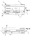
- FIGS. 3, 3a, 4, 4a and 7 give a corresponding impression of the arrangement of interest for the method and in particular the location of the procedural relevant Objects.
- the stringer 3 is an upper and a lower belt 4, 5 is integrated, which are arranged horizontally and together with a perpendicular to them web 6 make the stringer 3 [a spar or a carrier], can be both as a belt support surface 8 (geng.) designated bearing surface of the upper belt 4 or lower belt 5 one (generally designated) selected surface area 13 of the shell surface. 9 the shell 2 (of the considered skin field) lie flat in accordance with the surface, with the other Considerations of a horizontal position of the two Run out of bearing surfaces.
- the upper and lower strap 4, 5 are also known in practice as "stringer foot” and equally the web 6 referred to as "stringer web” (See Figures 3, 3a, 4, 4a and 7). With the final positioning of the relevant Belt support surface 8 on the selected Surface area 13 would be the prerequisites for intended joining of these bearing surfaces completed.
- This detected scanner result is then done by the evaluation logic after electronic conversion (according to the example of FIG. 2) to the mentioned control unit 12 for implementation subordinate procedural steps transmitted.
- Control unit 12 the (not desired) joint gap 1 for each scanned gap s between the selected surface area 13 (the shell surface 9) and the belt support surface 8 (of the lower belt 5) computationally (by supporting a Computer simulation) is determined.
- the fissured Distance s, the surface supports of the lower belt. 5 and the selected surface area 13 is shown in Figures 3 and 3a.
- the y-coordinate direction refers to the vertical distance from one of the low points e, f or the high points i, j of the curved (curved) Deepening or increasing the surface of the Surface support of the selected surface area 13 to the perpendicular low e, f or High point i, j of the curved (curved) depression or increasing the surface of the belt support surface 8, this vertical distance with the (in the three coordinate directions x, y, z changing) vertical fissile distance s will correlate.
- control unit 12 the (at a glance on the figures 3 and 3a detected) vertical fissile distance s between or beside (located) the relevant bearing surfaces on a fictitious (only assumed) defined distance line L, the Horizontally located the selected surface area 13 of the shell surface 9 and the Gurtauflage Chemistry 8 of spans lower belt 5.
- This fictitious distance line L becomes (after the model Fig. 3) in the y-coordinate direction vertically (highest) (punctual or areal) first and second contact area BB, ZZ, the selected surface area 13 and the Belt support surface 8 (ie: the contact surfaces) of both Objects lying on top of each other (shell 2 and lower Strap 5 of the stringer 3) at the point of their touch limit, tangent.
- the aforementioned step can be possibly also with the control unit 12, the (on the model of Fig. 2) information technology via a further signal line 11 with a Computer unit 16 is connected, so implement, after which (with a view of Fig. 4) with the latter in the context of a computer simulation first a first vertical distance c is determined, which is between a simulated (technically: imitated) second Distance line A and a first low point e, the this second distance line A vertically spaced is located and on the selected surface area 13 of the shell surface 9 is located.
- a second vertical Distance d to be determined which is between a simulated (technically: imitated) third Distance line B and a second perpendicular to the third Distance line B spaced trough f area-related geometric deviation of Belt support surface 8 is located.
- the latter will be the Take control unit 12 with the detection logic, wherein the computer unit 16 (possibly on request) the informative vertical distances c, d of the Provide and transfer the control unit digitally becomes.
- Control unit 12 is an addition of the vertical Distances c, d for each scanned surface area perform computationally, this (the changing) fissile distance s by an addition the vertical distance c and the vertical distance Determine d for each laser beam swept deviation becomes.
- this control unit 12 (after the Model of Fig. 3a) a fictitious distance line L take into account the in y coordinate direction vertically located (punctual or areal) third contact area YY, the raised Bearing surfaces (the elevations) of the selected one Surface area 13 of the shell surface 9 and the Belt support surface 8 (ie: the contact surfaces) of both Objects lying on top of each other (shell 2 and lower Belt 5 of the stringer 3) at the point (s) of their Narrow the touch, tangent.
- this aforementioned step can be possibly with the control unit 12, the (after the example of FIG. 2) information technology over the another signal line 11 with the computer unit 16 connected, so also implement, according to which (with a view of Fig. 4a) with the latter in the frame the mentioned computer simulation initially a third vertical distance g is determined, which is between a first high point i of the area-related geometric Deviation of the surface area 13 of Shell surface 9, which simulated on a (technical imitated) fourth distance line C, and a perpendicular to the fourth distance line C spaced located first plane point k of the surface area 13 of the shell surface 9 is located.
- a fourth vertical distance h which determines between a second high point j (the area-related geometric Deviation of the Gurtauflage Structure 8), on a simulated fifth distance line D, and a perpendicular to the fifth distance line D spaced located second plane point 1 of the belt support surface. 8 lies.
- both the (vertical) third as also the fourth vertical distance g, h, which is (both) over the two coordinate directions x, z in Change the direction of the y-coordinate direction, the mentioned area-related geometric deviation the surface area 12 of the shell surface 9 and the Gurtauflage Materials 8 correspond, which the Control unit 12 with the integrated Capture logic separately.
- the first and second high point i, j and the first and second Layer point k, 1, the control unit 12 with the Record acquisition logic, the computer system 16 (if necessary on request) the informative vertical Distances g, h of the control unit 12 digital provide and transfer.
- the two simulated distance lines C, D correspond a simulated (technically imitated) horizontally lying line, each of the width b of selected surface area 13 and the Be spanning belt support surface 8 and the geometrically deviating from a regularity raised support surfaces (the elevations) of the objects, those next to each other a second and third Joint gap 11, 12 is adjacent, tangentially become. Subsequently, the addition of this vertical distances g, h for each scanned Surface area are determined by computer technology.
- each one Area (pad) area of one of the two objects will not deviate from a regularity, - the Determining the first or second vertical distance c, d and the third or fourth vertical distance g, h will be useful.
- the Determining the first or second vertical distance c, d and the third or fourth vertical distance g, h will be useful.
- the situation after Fig. 4 will be a recess of the selected Surface area 13 of the shell surface 9 or the contemplated Gurtauflage Chemistry 4, 5
- an increase in Bearing surfaces of the two objects (shell 2 and lower or upper belt 4, 5) of the consideration is based.
- the control unit 12 is based on her known (and possibly in a her integrated Storage unit stored) information with the evaluation logic the computational determination of a Fill the product 14, which is to compensate for the relevant joint gap 1, 11, 12 (according to the figures 3, 3a) is needed.
- This filling material 14 is regarding its quantity, geometry and volume through the Control unit 12 computationally determined, wherein (with a view of Fig. 2) the Determination result via an additional signal line 11 to a filling (metering) device 15 transmitted becomes. The latter is with an ultrasonic cutter objectified.
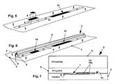
- Fig. 5 gives the Viewers a view according to the filling 14th for example, the filling slot 1 of the selected Surface area 13, as shown in FIG. 7 clearer shown already filled.
- Fig. 6 is a Stringer 3, who (in this situation) the selected surface area 13 of the shell surface. 9 is spaced apart.
- the Gurtauflage Chemistry 8 of lower belt 5 will later conform to the surface selected surface area 13 of the shell surface. 9 the shell 2 (the skin panel) lying on the model of Fig. 7 stored on the contents 14.
- contents 14 and / or used Patches 14a of a force-transmitting plastic-like material preferably made of GFK, CFK or a similar material, wherein a additional networking of the filling pieces 14a (off Haftrichn) with a resin film would be conceivable.
- the Gurtauflage Structure 8 should advantageously on the selected surface area 13 of the Tray surface 9 are positioned so that the Filling material 14 or the filling pieces 14 a the gapy Distance s of the first Artspaltes 1 between the Bearing surfaces of both objects (shell 2, lower or upper belt 4, 5) completely fill and equally this joint gap 1 perfect be included. Otherwise, the (by Increases of the Gurtauflage composition 8) divided selected surface area 13 from outside the Joining partner before and behind [thus: beside the Elevations) along the extended support surface (s) the objects] with the contents 14 or the filling pieces 14a be relined.
- the two thick (wall) joining partners are made of one plastic-like and in particular from a carbon fiber reinforced plastic material, wherein the stringer 3 or the shell 2 (the zu stiffening skin field) certainly also from one Light metal, for example, an aluminum or made of aluminum alloys.
- the carbon fiber reinforced materials will be on a Refer to CFK or GFK or similar material.
- the intended joining surfaces on the shell 2 and on (Strap 4, 5 of the) Stringer (s) 3 are fully automatic on existing geometric deviations from one Regularity studied.
- This joining surfaces correlates with the compensation of these Deviations that are generally determined by the finding of various slit patterns with one different slot-like depression or of various (possibly wavy) mountain patterns with geometrically deviating from a regularity) raised support surface (s) of the objects expresses.
- one is in practice at the available Foreseen joining partners usually (at least) the Arrangement with a first or (only) a second and / or (only) a third joining slot 1, 11, 12 encountered, the examined joining surfaces in their Pad to include each other, with the noted Deviations with a filling material (filling 14, Filled pieces 14a) of the specified type are balanced, just to the then intended joining of the two to realize specified joining partners problem-free.
- the required filling material is supported an ultrasonic cutter or a metering device Fully automatic according to quantity, volume and scope provided and to compensate for the joining gaps 1, 11, 12 used. The filler compensation can Hand-distributed or transported loaded happen.
Landscapes
- Engineering & Computer Science (AREA)
- Mechanical Engineering (AREA)
- Lining Or Joining Of Plastics Or The Like (AREA)
- Length Measuring Devices By Optical Means (AREA)
- Length Measuring Devices With Unspecified Measuring Means (AREA)
- Moulds For Moulding Plastics Or The Like (AREA)
- Application Of Or Painting With Fluid Materials (AREA)
- Paper (AREA)
- Separation By Low-Temperature Treatments (AREA)
- Adhesives Or Adhesive Processes (AREA)
- Automatic Assembly (AREA)
Abstract
Description
- Fig. 1
- eine Anordnung mit einer Scannereinheit zum Scannen einer Schalenfläche;
- Fig. 2
- eine Anordnung mit einer Scannereinheit zum Scannen der Gurtoberfläche eines Stringers und eine Darstellung weiterer Einheiten zur Umsetzung des Verfahrens, die der Scannereinheit verbunden sind;
- Fig. 3
- die Anordnung der aufliegenden Fügepartner mit Darstellung eines ersten auszugleichenden Fügespaltes;
- Fig. 3a
- die Anordnung der aufliegenden Fügepartner mit Darstellung eines zweiten und dritten auszugleichenden Fügespaltes;
- Fig. 4
- die Anordnung von beabstandeten Fügepartnern mit einer Darstellung von deren nach innen gewölbten Auflagefläche;
- Fig. 4a
- die Anordnung von beabstandeten Fügepartnern mit einer Darstellung von deren erhobenen (nach außen gewölbten) Auflagefläche;
- Fig. 5
- die Darstellung einer Schalenfläche mit deren nach innen gewölbten und mit einem Füllgut ausgeglichenen Vertiefung inmitten eines ausgewählten Oberflächenbereiches der Schalenfläche;
- Fig. 6
- die Darstellung des ausgewählten Oberflächenbereiches nach Fig. 5 mit einem dem Oberflächenbereich beabstandet angeordneten Stringer;
- Fig. 7
- die Anordnung nach Fig. 3 mit Darstellung des mit dem Füllgut ausgeglichenen Fügespaltes.
Claims (19)
- Verfahren zum Ausgleichen eines Fügespaltes (1), den zwei aufeinander liegende Flächen von einer Schale (2) und einem Stringer (3) einschließen, bei dem eine Auflagefläche eines oberen oder unteren Gurtes (4, 5), die horizontal angeordnet werden und zusammen mit einem zu ihnen senkrecht stehenden Steg (6) den Stringer (3) bilden, auf einer Schalenfläche (9) der horizontal angeordneten Schale (2) positioniert wird, die durch Fügen miteinander verbunden werden, und bei dem durch eine Scannereinheit (7) bestehende geometrische Abweichungen von einer Ebenmäßigkeit einer Gurtauflagefläche (8) des oberen oder unteren Gurtes (4, 5) und der Schalenfläche (9) durch horizontale oder vertikale und punkt- oder zeilenweise Abtastung der Gurtauflagefläche (8) oder der Schalenfläche (9) mit einem Lichtstrahl (10) erfasst und darauf folgend elektronisch gewandelt werden, wobei das erfasste Scannerergebnis nach geschehener Wandlung über eine Signalleitung (11) an eine Kontrolleinheit (12) weitergeleitet wird, gekennzeichnet durch folgende Schritte, nach denena) zuerst ein ausgewählter Oberflächenbereich (13) der Schalenfläche (9), auf dem die betreffende Gurtauflagefläche (8) später positioniert wird, und danach die Oberfläche dieser Gurtauflagefläche (8) vollständig mit dem Lichtstrahl (10) abgetastet wird oder in einer umgekehrten Reihenfolge,b) dann durch die Kontrolleinheit (12) der Fügespalt (1) für jeden abgetasteten spaltigen Abstand (s) zwischen dem ausgewählten Oberflächenbereich (13) der Schalenfläche (9) und der Gurtauflagefläche (8) des betreffenden Gurtes (4, 5) rechentechnisch ermittelt wird, wobei die Kontrolleinheit (12) den vertikalen spaltigen Abstand (s) zwischen den betreffenden Auflageflächen auf eine fiktiv definierte Abstandslinie (L) beziehen wird, die horizontal gelegen den ausgewählten Oberflächenbereich (13) der Schalenfläche (9) und die Gurtauflagefläche (8) überspannt und einem betreffenden horizontal gelegenen Berührungsbereich (BB, YY, ZZ), den die Auflageflächen beider aufeinander liegenden Objekte an der Stelle ihrer Berührung eingrenzen, tangential anliegt,c) danach ein Füllgut (14), das zum Ausgleichen des Fügespaltes (1, 11, 12) benötigt wird, hinsichtlich dessen Menge, Geometrie und Volumen durch die Kontrolleinheit (12) rechentechnisch ermittelt wird, wobei das Ermittlungsergebnis über eine weitere Signalleitung (11) an eine Füllmasseneinrichtung (15) übermittelt wird,d) darauffolgend das ermittelte Volumen des Füllgutes (14), das die Füllmasseneinrichtung (15) bereitstellen wird, in Korrelation von dessen Geometrie dem ausgewählten Oberflächenbereich (13) der Schalenfläche (9) aufgefüllt wird, sofern ein spaltiger Abstand (s) nach dem Schritt b ermittelt wird,e) anschließend die Gurtauflagefläche (8) auf dem ausgewählten Oberflächenbereich (13) der Schalenfläche (9) positioniert wird, wodurch der spaltige Abstand (s) zwischen oder neben den Auflageflächen mit dem Füllgut (14) ausgeglichen wird.
- Verfahren nach Anspruch 1, dadurch gekennzeichnet, daß der Schritt b) mit einer der Kontrolleinheit (12) informationstechnisch verbundenen Computereinheit (16) realisiert wird, mit der im Rahmen einer Computersimulation zunächst ein erster vertikaler Abstand (c) ermittelt wird, der zwischen einer simulierten zweiten Abstandslinie (A) und einem ersten lotrecht der zweiten Abstandslinie (A) beabstandet gelegenen Tiefpunkt (e) der flächenbezogenen geometrischen Abweichung des Oberflächenbereiches (13) der Schalenfläche (9) liegt, und danach ein zweiter vertikaler Abstand (d) ermittelt wird, der zwischen einer simulierten dritten Abstandslinie (B) und einem zweiten lotrecht der dritten Abstandslinie (B) beabstandet gelegenen Tiefpunkt (f) der flächenbezogenen geometrischen Abweichung der Gurtauflagefläche (8) liegt, wobei die beiden simulierten Abstandslinien (A, B) einer horizontal gelegenen Linie entsprechen werden, welche jeweils die Breite des ausgewählten Oberflächenbereiches (13) und der Gurtauflagefläche (8) überspannen werden und breitenseitlich eines ersten Fügespaltes (1) den geometrisch nicht von einer Ebenmäßigkeit abweichenden Auflageflächen der Objekte tangential anliegen werden, und darauffolgend die Addition dieser vertikalen Abstände (c, d) für jeden abgescannten Flächenbereich rechentechnisch ermittelt werden.
- Verfahren nach Anspruch 1, dadurch gekennzeichnet, daß der Schritt b) mit einer der Kontrolleinheit (12) informationstechnisch verbundenen Computereinheit (16) realisiert wird, mit der im Rahmen einer Computersimulation zunächst ein dritter vertikaler Abstand (g) ermittelt wird, der zwischen einem ersten Hochpunkt (i) der flächenbezogenen geometrischen Abweichung des Oberflächenbereiches (13) der Schalenfläche (9), der auf einer simulierten vierten Abstandslinie (C) liegt, und einem lotrecht der vierten Abstandslinie (C) beabstandet gelegenen ersten Ebenenpunkt (k) des Oberflächenbereiches (13) der Schalenfläche (9) liegt, und danach ein vierter vertikaler Abstand (h) ermittelt wird, der zwischen einem zweiten Hochpunkt (j) der flächenbezogenen geometrischen Abweichung der Gurtauflagefläche (8) liegt, der auf einer simulierten fünften Abstandslinie (D) liegt und einem lotrecht der fünften Abstandslinie (D) beabstandet gelegenen zweiten Ebenenpunkt (1) der Gurtauflagefläche (8) liegt, wobei die beiden simulierten Abstandslinien (C, D) einer horizontal gelegenen Linie entsprechen werden, welche jeweils die Breite des ausgewählten Oberflächenbereiches (13) und der Gurtauflagefläche (8) überspannen werden und den geometrisch von einer Ebenmäßigkeit abweichenden erhobenen Auflageflächen der Objekte, denen nebengelegen jeweils ein zweiter und dritter Fügespalt (11, 12) angrenzen wird, tangential anliegen werden, und darauffolgend die Addition dieser vertikalen Abstände (g, h) für jeden abgescannten Flächenbereich rechentechnisch ermittelt werden.
- Verfahren nach Anspruch 2, dadurch gekennzeichnet, daß entweder der erste oder der zweite vertikale Abstand (c, d) ermittelt wird, wobei die Ermittlung von einem dieser beiden Abstände (c, d) entfallen wird, da entweder der Oberflächenbereich (13) der Schalenfläche (9) oder die Gurtauflagefläche (8) des betreffenden Gurtes (4, 5) geometrisch nicht von einer Ebenmäßigkeit abweichen wird.
- Verfahren nach Anspruch 3, dadurch gekennzeichnet, daß entweder der dritte oder der vierte vertikale Abstand (g, h) ermittelt wird, wobei die Ermittlung von einem dieser beiden Abstände (g, h) entfallen wird, da entweder der Oberflächenbereich (13) der Schalenfläche (9) oder die Gurtauflagefläche (8) des betreffenden Gurtes (4, 5) geometrisch nicht von einer Ebenmäßigkeit abweichen wird.
- Verfahren nach den Ansprüchen 4 und 5, dadurch gekennzeichnet, daß ein sich mit dem dritten vertikalen Abstand (g) erhebender Objektteil der Schale (2) oder ein sich mit dem vierten vertikalen Abstand (h) erhebender Objektteil des betreffenden Gurtes (4, 5) dem ersten Fügespalt (1), der mit einer flächenweise vorhandenen Vertiefung des ausgewählten Oberflächenbereiches (13) der Schalenfläche (9) oder der Gurtauflagefläche (8) des betreffenden Gurtes (4, 5) vorhanden ist, fixiert wird, unter der Voraussetzung, dass der betreffende erhebende Objektteil mit dem ersten Fügespalt (1) korrespondieren wird.
- Verfahren nach den Ansprüchen 2 bis 6, dadurch gekennzeichnet, daß der spaltige Abstand (s) des ersten Fügespaltes (1) durch eine Addition des ersten vertikalen Abstandes (c) und des vertikalen Abstandes (d) oder derjenige des zweiten und des dritten Fügespaltes (11, 12) durch die Addition des dritten vertikalen Abstandes (g) und des vierten vertikalen Abstandes (h) für jede abgetastete Abweichung ermittelt wird, wobei der spaltige Abstand (s) im Ausnahmefall nur durch den ersten oder zweiten und durch den dritten oder vierten vertikalen Abstand (c, d) für jede abgetastete Abweichung ermittelt wird.
- Verfahren nach Anspruch 1, dadurch gekennzeichnet, daß mit dem Lichtstrahl (10) ein rechteckförmiger Oberflächenbereich (13) auf der Schalenfläche (9) abgetastet wird, wobei die Maßhaltigkeit des Oberflächenbereiches (13) und der Gurtauflagefläche (8) hinsichtlich der Breitenund Längenmaße der Objekte aufeinander abgestimmt werden.
- Verfahren nach Anspruch 1, dadurch gekennzeichnet, daß als Füllgut (14) Füllstücke (14a) verwendet werden, deren Anzahl und Geometrie auf Basis des ermittelten Füllgut-Volumens durch die Kontrolleinheit (12) bestimmt wird.
- Verfahren nach den Ansprüchen 1 und 9, dadurch gekennzeichnet, daß ein Ultraschallcutter als Füllmasseneinrichtung (15) verwendet wird, der das bereitgestellte Füllgut (14) zu Füllstücke (14a) verarbeiten wird.
- Verfahren nach Anspruch 10, dadurch gekennzeichnet, daß mit einem dem Ultraschallcutter integrierten Ultraschallmesser aus dem bereitgestellten Füllgut (14) die Füllstücke (14a) zugeschnitten und / oder geometrisch geformt werden.
- Verfahren nach den Ansprüchen 1 und 9, dadurch gekennzeichnet, daß einer als Dosiereinrichtung verwendeten Füllmasseneinrichtung (15) ein pulverförmiges oder pastöses Füllgut (14) bereitgestellt wird, das nach Schritt e von ihr dem spaltigen Abstand (s) dosiert wird, mit dem der spaltige Abstand (s) ausgeglichen wird.
- Verfahren nach Anspruch 1, dadurch gekennzeichnet, daß die geometrischen Abweichungen von einer Ebenmäßigkeit der Schalen- oder Gurtauflagefläche (8, 9) auf eine konturenbezogene Vertiefung oder Erhöhung der Flächen bezogen wird.
- Verfahren nach den Ansprüchen 1 und 13, dadurch gekennzeichnet, daß das Füllgut (14) entweder handverlesen oder durch die Füllmasseneinrichtung (15) der Vertiefung des Oberflächenbereiches (13) aufgefüllt und angehäuft wird.
- Verfahren nach Anspruch 1, dadurch gekennzeichnet, daß dicke und starre Stringer (3) aus einem Kunststoff oder einem Metall sowie dickwandige und starre Schalen (2) aus einem Kunststoff oder einem Metall, die sich auf ein zu versteifendes Hautfeld beziehen und auf denen die Gurtauflagefläche (8) des Stringers (3) positioniert wird, verwendet werden.
- Verfahren nach Anspruch 15, dadurch gekennzeichnet, daß ein kohlenfaserverstärkter Kunststoff-Werkstoff, vorzugsweise ein CFK- oder GFK- oder artähnlicher Werkstoff und anstelle des Metalls ein Leichtmetall-Werkstoff, vorzugsweise ein Aluminium-Werkstoff, verwendet wird.
- Verfahren nach Anspruch 11, dadurch gekennzeichnet, daß das Füllgut (14) mit mehreren Füllstücken (14a), die aus einem kraftübertragenden Werkstoff, vorzugsweise aus GFK oder CFK, bestehen und zusätzlich mit einem Harzfilm versetzt werden, realisiert wird.
- Verfahren nach den Ansprüchen 1, 3 und 9, dadurch gekennzeichnet, daß nach dem Schritt e) die Gurtauflagefläche (8) auf dem ausgewählten Oberflächenbereich (13) der Schalenfläche (9) dermaßen positioniert wird, dass das Füllgut (14) oder die Füllstücke (14a) den spaltigen Abstand (s) zwischen oder neben den Auflageflächen beider Objekte vollständig ausfüllen und gleichermaßen dem betroffenen Fügespalt (1, 11, 12) vollkommen eingeschlossen werden.
- Verfahren nach Anspruch 1, dadurch gekennzeichnet, daß der Lichtstrahl (10) von einer der Scannereinheit (7) integrierten Laserquelle bereitgestellt wird, mit dem die Gurtauflagefläche (8) und danach der ausgewählte Oberflächenbereich (13) oder in umgekehrter Reihenfolge abgetastet wird.
Applications Claiming Priority (2)
| Application Number | Priority Date | Filing Date | Title |
|---|---|---|---|
| DE10319926A DE10319926B4 (de) | 2003-05-02 | 2003-05-02 | Verfahren zum Ausgleichen eines Fügespaltes |
| DE10319926 | 2003-05-02 |
Publications (2)
| Publication Number | Publication Date |
|---|---|
| EP1473142A1 true EP1473142A1 (de) | 2004-11-03 |
| EP1473142B1 EP1473142B1 (de) | 2006-05-24 |
Family
ID=32981212
Family Applications (1)
| Application Number | Title | Priority Date | Filing Date |
|---|---|---|---|
| EP04009488A Expired - Lifetime EP1473142B1 (de) | 2003-05-02 | 2004-04-22 | Verfahren zum Ausgleichen eines Fügespaltes |
Country Status (7)
| Country | Link |
|---|---|
| US (2) | US7208057B2 (de) |
| EP (1) | EP1473142B1 (de) |
| JP (1) | JP4427381B2 (de) |
| AT (1) | ATE327090T1 (de) |
| CA (2) | CA2736941C (de) |
| DE (2) | DE10319926B4 (de) |
| ES (1) | ES2264063T3 (de) |
Cited By (9)
| Publication number | Priority date | Publication date | Assignee | Title |
|---|---|---|---|---|
| WO2007034197A1 (en) * | 2005-09-22 | 2007-03-29 | Airbus Uk Limited | Assembly of aircraft components |
| WO2007068949A1 (en) * | 2005-12-16 | 2007-06-21 | Airbus Uk Limited | Assembly of aircraft components |
| WO2009044362A3 (en) * | 2007-10-03 | 2009-06-11 | Alenia Aeronautica Spa | A method of manufacturing wing structures. |
| ES2396327A1 (es) * | 2010-06-10 | 2013-02-20 | Airbus Operations, S.L. | Procedimiento para la fabricación de piezas grandes de material compuesto controlando el espesor de sus bordes |
| WO2013164101A1 (de) * | 2012-05-03 | 2013-11-07 | Dürr Systems GmbH | Rotorblattherstellvorrichtung und zugehöriges verfahren |
| EP2203793B1 (de) * | 2007-10-23 | 2014-08-06 | Airbus Operations Limited | Tragflächenstruktur und verfahren zur herstellung einer rippe für eine tragflächenstruktur |
| CN108151660A (zh) * | 2017-12-29 | 2018-06-12 | 西北工业大学 | 一种飞机部件对接间隙和阶差的测量装备、方法及系统 |
| CN109945847A (zh) * | 2019-03-20 | 2019-06-28 | 武汉建工集团股份有限公司 | 一种基于标线仪的墙面监测方法及系统 |
| CN112060630A (zh) * | 2020-07-15 | 2020-12-11 | 成都飞机工业(集团)有限责任公司 | 一种基于自动铺丝技术的铺层理论厚度测算方法 |
Families Citing this family (26)
| Publication number | Priority date | Publication date | Assignee | Title |
|---|---|---|---|---|
| US7080805B2 (en) * | 2004-05-05 | 2006-07-25 | The Boeing Company | Stiffened structures and associated methods |
| US7756321B2 (en) * | 2007-02-28 | 2010-07-13 | The Boeing Company | Method for fitting part assemblies |
| US7787979B2 (en) * | 2007-03-14 | 2010-08-31 | The Boeing Company | Splicing fuselage sections without shims |
| GB0720702D0 (en) * | 2007-10-23 | 2007-12-05 | Airbus Uk Ltd | A shim for arrangement against a structural component and a method making a shim |
| US9034128B2 (en) * | 2007-12-17 | 2015-05-19 | The Boeing Company | Fitting doublers using gap mapping |
| DE102008012055B3 (de) * | 2008-02-29 | 2009-10-01 | Airbus Deutschland Gmbh | Verfahren zum Toleranzausgleich zwischen zwei Faserverbundbauteilen |
| DE102010010686A1 (de) | 2009-03-19 | 2011-01-05 | Fraunhofer-Gesellschaft zur Förderung der angewandten Forschung e.V. | Verfahren und Vorrichtung zum klebtechnischen Fügen großflächiger Komponenten im Fahrzeugbau |
| DE102010010685A1 (de) * | 2009-03-19 | 2011-02-03 | Airbus Operations Gmbh | Verfahren zur toleranzangepassten Klebstoffapplikation im Fahrzeugbau |
| SG194130A1 (en) * | 2011-04-12 | 2013-11-29 | Pixeloptics Inc | Adhesive dispensing profile enhancement |
| US8756792B2 (en) * | 2011-06-08 | 2014-06-24 | The Boeing Company | Digitally designed shims for joining parts of an assembly |
| US8865487B2 (en) * | 2011-09-20 | 2014-10-21 | General Electric Company | Large area hermetic encapsulation of an optoelectronic device using vacuum lamination |
| DE102012104024A1 (de) | 2012-05-08 | 2013-11-14 | SaarGummi technologies S.à.r.l. | Verfahren zur Bildung einer Dichtung oder Abdeckung an einer Öffnung einer Fahrzeugkarosserie |
| EP2703149B1 (de) * | 2012-09-04 | 2015-06-17 | Airbus Operations GmbH | Verfahren zur Herstellung einer Flugzeugstrukturkomponente mit einer Außenhaut mit einer glatten Außenfläche |
| US9358764B2 (en) * | 2013-12-17 | 2016-06-07 | The Boeing Company | System and method of joining components |
| US9990446B2 (en) * | 2014-04-15 | 2018-06-05 | The Boeing Company | Predictive shimming for flexible surfaces |
| DE102014013533A1 (de) * | 2014-09-12 | 2016-03-17 | Airbus Operations Gmbh | Zusammengefügte Faserverbundbauteile für Luft- oder Raumfahrzeuge und Verfahren zu Herstellung derselben |
| CN104634488B (zh) * | 2015-02-06 | 2017-04-19 | 西北工业大学 | 一种飞机复合材料长桁变形测量方法及装置 |
| US10350839B2 (en) * | 2015-05-21 | 2019-07-16 | The Boeing Company | Remote advanced repair guidance |
| US10350634B2 (en) * | 2015-07-31 | 2019-07-16 | Apple Inc. | Method for smoothing substrate surface |
| DE102015114359A1 (de) | 2015-08-28 | 2017-03-02 | Airbus Operations Gmbh | Spannsystem zum Positionieren eines ersten Bauteils und eines zweiten Bauteils zueinander sowie Verfahren zum Herstellen eines Maßausgleichs zwischen zwei Bauteilen |
| US10493705B2 (en) * | 2015-11-13 | 2019-12-03 | GM Global Technology Operations LLC | Additive manufacturing of a body component on a tube frame |
| DE102016110349A1 (de) * | 2016-06-03 | 2017-12-07 | Airbus Operations Gmbh | Verfahren und Vorrichtung zum Ermitteln einer Montageebene für ein Bauteil |
| CN107839333A (zh) * | 2017-10-27 | 2018-03-27 | 京东方科技集团股份有限公司 | 基板贴合方法及基板贴合设备 |
| GB201719790D0 (en) * | 2017-11-28 | 2018-01-10 | Airbus Operations Gmbh | Aircraft joint with a curable composite bushing |
| RU2753052C1 (ru) * | 2020-09-07 | 2021-08-11 | Российская Федерация, от имени которой выступает Министерство обороны Российской Федерации (Минобороны России) | Устройство капотирования элементов соединения стыков отсеков летательного аппарата |
| CN120773378A (zh) * | 2025-08-19 | 2025-10-14 | 沈阳飞机工业(集团)有限公司 | 一种缘条变曲率复合材料c型梁成型工装及成型方法 |
Citations (5)
| Publication number | Priority date | Publication date | Assignee | Title |
|---|---|---|---|---|
| US4980005A (en) * | 1987-03-13 | 1990-12-25 | The Boeing Company | Method for producing an aerospace structure having a cast-in-place noncompressible void filler |
| DE4136653A1 (de) * | 1991-11-07 | 1993-05-13 | Lenhardt Maschinenbau | Verfahren und vorrichtung zum fuellen der randfuge einer isolierglasscheibe mit einer dichtmasse |
| US5385050A (en) * | 1992-04-07 | 1995-01-31 | Northrop Grumman Corporation | Gap measurement for shim manufacture |
| EP1004361A2 (de) * | 1998-11-27 | 2000-05-31 | Rover Group Limited | Verfahren zur Abgabe von Klebstoff |
| US20020078545A1 (en) * | 1996-03-22 | 2002-06-27 | Munk Clayton L. | Determinant wing assembly |
Family Cites Families (10)
| Publication number | Priority date | Publication date | Assignee | Title |
|---|---|---|---|---|
| US3041231A (en) * | 1959-06-11 | 1962-06-26 | Ed Fountain Lumber Co | Method of making laminated boards from rotten grade wood |
| US4147576A (en) * | 1977-03-02 | 1979-04-03 | Beem Lewis W | Method of repairing a vehicle body |
| JPS58501582A (ja) * | 1981-09-30 | 1983-09-22 | ザ ボ−イング コンパニ− | 複合構造物における外板と桁部材とを接続する為の継ぎ手 |
| US5963660A (en) * | 1996-09-26 | 1999-10-05 | The Boeing Company | Method and apparatus for detecting and measuring laps and gaps in composite materials |
| US5879540A (en) * | 1997-07-25 | 1999-03-09 | Occidental Chemical Corporation | Process for reducing corrosion in a system for separating aromatic hydrocarbons from a mixture with aliphatic hydrocarbons |
| DE19739885A1 (de) * | 1997-09-11 | 1999-03-18 | Bernd Klose | Komparativer Oberflächenqualifizierer |
| US6174392B1 (en) * | 1999-03-04 | 2001-01-16 | Northrop Grumman Corporation | Composite structure repair process |
| BR0117299B1 (pt) * | 2000-03-03 | 2014-11-25 | Quickstep Technologies Pty Ltd | Métodos para unir componentes compósitos |
| US6385836B1 (en) * | 2000-06-30 | 2002-05-14 | Lockheed Martin Corporation | Method for composite material repair |
| US6849150B1 (en) * | 2001-01-16 | 2005-02-01 | Lockheed Martin Corporation | System and method of forming structural assemblies with 3-D woven joint pre-forms |
-
2003
- 2003-05-02 DE DE10319926A patent/DE10319926B4/de not_active Expired - Fee Related
-
2004
- 2004-04-22 AT AT04009488T patent/ATE327090T1/de not_active IP Right Cessation
- 2004-04-22 DE DE502004000607T patent/DE502004000607D1/de not_active Expired - Lifetime
- 2004-04-22 ES ES04009488T patent/ES2264063T3/es not_active Expired - Lifetime
- 2004-04-22 EP EP04009488A patent/EP1473142B1/de not_active Expired - Lifetime
- 2004-04-28 JP JP2004133218A patent/JP4427381B2/ja not_active Expired - Fee Related
- 2004-05-03 US US10/838,652 patent/US7208057B2/en not_active Expired - Fee Related
- 2004-05-03 CA CA2736941A patent/CA2736941C/en not_active Expired - Fee Related
- 2004-05-03 CA CA2466003A patent/CA2466003C/en not_active Expired - Fee Related
-
2006
- 2006-08-03 US US11/498,668 patent/US7279056B2/en not_active Expired - Fee Related
Patent Citations (5)
| Publication number | Priority date | Publication date | Assignee | Title |
|---|---|---|---|---|
| US4980005A (en) * | 1987-03-13 | 1990-12-25 | The Boeing Company | Method for producing an aerospace structure having a cast-in-place noncompressible void filler |
| DE4136653A1 (de) * | 1991-11-07 | 1993-05-13 | Lenhardt Maschinenbau | Verfahren und vorrichtung zum fuellen der randfuge einer isolierglasscheibe mit einer dichtmasse |
| US5385050A (en) * | 1992-04-07 | 1995-01-31 | Northrop Grumman Corporation | Gap measurement for shim manufacture |
| US20020078545A1 (en) * | 1996-03-22 | 2002-06-27 | Munk Clayton L. | Determinant wing assembly |
| EP1004361A2 (de) * | 1998-11-27 | 2000-05-31 | Rover Group Limited | Verfahren zur Abgabe von Klebstoff |
Cited By (14)
| Publication number | Priority date | Publication date | Assignee | Title |
|---|---|---|---|---|
| EP2216248A1 (de) * | 2005-09-22 | 2010-08-11 | Airbus Operations Limited | Anordnung von Flugzeugkomponenten |
| WO2007034197A1 (en) * | 2005-09-22 | 2007-03-29 | Airbus Uk Limited | Assembly of aircraft components |
| RU2485024C2 (ru) * | 2005-09-22 | 2013-06-20 | Эйрбас Оперейшнз Лимитед | Способ сборки частей летательного аппарата с образованием узла летательного аппарата (варианты), узел летательного аппарата и набор прокладок |
| US8479394B2 (en) | 2005-09-22 | 2013-07-09 | Airbus Operations Limited | Assembly of aircraft components |
| WO2007068949A1 (en) * | 2005-12-16 | 2007-06-21 | Airbus Uk Limited | Assembly of aircraft components |
| US8220131B2 (en) | 2005-12-16 | 2012-07-17 | Airbus Operations Limited | Assembly of aircraft components |
| CN101331060B (zh) * | 2005-12-16 | 2012-11-28 | 空中客车英国运营有限责任公司 | 飞机部件的组装 |
| WO2009044362A3 (en) * | 2007-10-03 | 2009-06-11 | Alenia Aeronautica Spa | A method of manufacturing wing structures. |
| EP2203793B1 (de) * | 2007-10-23 | 2014-08-06 | Airbus Operations Limited | Tragflächenstruktur und verfahren zur herstellung einer rippe für eine tragflächenstruktur |
| ES2396327A1 (es) * | 2010-06-10 | 2013-02-20 | Airbus Operations, S.L. | Procedimiento para la fabricación de piezas grandes de material compuesto controlando el espesor de sus bordes |
| WO2013164101A1 (de) * | 2012-05-03 | 2013-11-07 | Dürr Systems GmbH | Rotorblattherstellvorrichtung und zugehöriges verfahren |
| CN108151660A (zh) * | 2017-12-29 | 2018-06-12 | 西北工业大学 | 一种飞机部件对接间隙和阶差的测量装备、方法及系统 |
| CN109945847A (zh) * | 2019-03-20 | 2019-06-28 | 武汉建工集团股份有限公司 | 一种基于标线仪的墙面监测方法及系统 |
| CN112060630A (zh) * | 2020-07-15 | 2020-12-11 | 成都飞机工业(集团)有限责任公司 | 一种基于自动铺丝技术的铺层理论厚度测算方法 |
Also Published As
| Publication number | Publication date |
|---|---|
| DE10319926B4 (de) | 2006-09-28 |
| CA2466003A1 (en) | 2004-11-02 |
| JP4427381B2 (ja) | 2010-03-03 |
| ES2264063T3 (es) | 2006-12-16 |
| JP2004331054A (ja) | 2004-11-25 |
| US20070107826A1 (en) | 2007-05-17 |
| US20040236454A1 (en) | 2004-11-25 |
| EP1473142B1 (de) | 2006-05-24 |
| US7279056B2 (en) | 2007-10-09 |
| US7208057B2 (en) | 2007-04-24 |
| CA2466003C (en) | 2011-10-04 |
| CA2736941A1 (en) | 2004-11-02 |
| CA2736941C (en) | 2012-07-10 |
| ATE327090T1 (de) | 2006-06-15 |
| DE10319926A1 (de) | 2004-11-25 |
| DE502004000607D1 (de) | 2006-06-29 |
Similar Documents
| Publication | Publication Date | Title |
|---|---|---|
| EP1473142B1 (de) | Verfahren zum Ausgleichen eines Fügespaltes | |
| DE3711470C2 (de) | ||
| DE10112629B4 (de) | Verfahren und Einrichtung zur variablen Herstellung von Laminatstrukturen | |
| DE69735994T2 (de) | Verfahren zum Montieren von Tragflächenholmen und Rippen mit engen Toleranzen | |
| DE102018204143B4 (de) | Additives Fertigungsverfahren | |
| DE602005002300T2 (de) | Ein Verfahren zur Herstellung eines strukturellen Verbundträgers für Flugzeuge | |
| DE60002344T2 (de) | Stereolithografisches verfahren zur herstellung von gegenständen mit verschiedene dichten aufweisenden zonen | |
| DE2208112A1 (de) | Verfahren zum Erzeugen einer nach Maß gefertigten Form zur Benutzung bei der Herstellung eines Bekleidungsstücks | |
| DE4313875C3 (de) | Vorrichtung zum Herstellen von Einsteckhüllen oder Einbanddecken | |
| DE102007047326A1 (de) | Vorrichtung zum Herstellen eines dreidimensionalen Objektes | |
| DE102014012425A1 (de) | Verfahren zum Herstellen eines dreidimensionalen Objekts | |
| DE102009060706A1 (de) | Verfahren sowie Vorrichtung zur Herstellung einer Versteifungsstruktur für ein Flugzeugrumpfsegment sowie eine Versteifungsstruktur | |
| DE102009006293A1 (de) | Verfahren zur Verringerung von Bandquerkrümmung und Bandschwingungen sowie Verfahren zur Herstellung von tauchbeschichteten Band nach dem Bandstabilisierungsverfahren | |
| DE2843544A1 (de) | Verfahren und vorrichtung zum schneiden eines laufenden bahnfoermigen materials | |
| EP2745945B1 (de) | Verfahren und Vorrichtung zur berührungslosen geometrischen Vermessung eines blechförmigen Messobjektes | |
| EP2447521B1 (de) | Automatisierungsvorrichtung und Verfahren zum Fertigen eines Rotorblatts einer Windenergieanlage | |
| WO2021063837A1 (de) | Verfahren zum beladen einer tafelablagevorrichtung einer flachbettwerkzeugmaschine und flachbettwerkzeugmaschine | |
| EP2700511B1 (de) | Verfahren zur Herstellung von beidseitig mit Dekorpapier beschichteten Platten und Dekorpapier zur Herstellung solcher Platten | |
| WO2023025717A1 (de) | Verfahren zum erfassen einer dicke einer folie oder platte, sowie anlage zur herstellung einer solchen folie oder platte und verfahren zum betreiben einer solchen anlage | |
| EP1708828B1 (de) | Bestimmung von koordinaten eines werkstücks | |
| DE102009054604B4 (de) | Verfahren und Vorrichtung zum teilweisen Durchtrennen eines Werkstücks | |
| DE102019210125A1 (de) | Kalibrierverfahren und Erfassungseinrichtung für eine Beschichtungseinheit einer additiven Herstellvorrichtung | |
| DE102009039578A1 (de) | Verfahren zum Herstellen eines dreidimensionalen Objektes im Wege eines generativen Herstellungsprozesses nach dem LOM-Verfahren | |
| DE102005038573B4 (de) | Variable Schichtungs-Rapid Prototyping-Vorrichtung zum Herstellen von großdimensionierten dreidimensionalen Objekten | |
| DE2536266A1 (de) | Verfahren zur herstellung laminierter materialbahnen mit festem kantenstreifen |
Legal Events
| Date | Code | Title | Description |
|---|---|---|---|
| PUAI | Public reference made under article 153(3) epc to a published international application that has entered the european phase |
Free format text: ORIGINAL CODE: 0009012 |
|
| AK | Designated contracting states |
Kind code of ref document: A1 Designated state(s): AT BE BG CH CY CZ DE DK EE ES FI FR GB GR HU IE IT LI LU MC NL PL PT RO SE SI SK TR |
|
| AX | Request for extension of the european patent |
Extension state: AL HR LT LV MK |
|
| 17P | Request for examination filed |
Effective date: 20050503 |
|
| AKX | Designation fees paid |
Designated state(s): AT BE BG CH CY CZ DE DK EE ES FI FR GB GR HU IE IT LI LU MC NL PL PT RO SE SI SK TR |
|
| GRAP | Despatch of communication of intention to grant a patent |
Free format text: ORIGINAL CODE: EPIDOSNIGR1 |
|
| GRAS | Grant fee paid |
Free format text: ORIGINAL CODE: EPIDOSNIGR3 |
|
| GRAA | (expected) grant |
Free format text: ORIGINAL CODE: 0009210 |
|
| AK | Designated contracting states |
Kind code of ref document: B1 Designated state(s): AT BE BG CH CY CZ DE DK EE ES FI FR GB GR HU IE IT LI LU MC NL PL PT RO SE SI SK TR |
|
| PG25 | Lapsed in a contracting state [announced via postgrant information from national office to epo] |
Ref country code: FI Free format text: LAPSE BECAUSE OF FAILURE TO SUBMIT A TRANSLATION OF THE DESCRIPTION OR TO PAY THE FEE WITHIN THE PRESCRIBED TIME-LIMIT Effective date: 20060524 Ref country code: IT Free format text: LAPSE BECAUSE OF FAILURE TO SUBMIT A TRANSLATION OF THE DESCRIPTION OR TO PAY THE FEE WITHIN THE PRESCRIBED TIME-LIMIT;WARNING: LAPSES OF ITALIAN PATENTS WITH EFFECTIVE DATE BEFORE 2007 MAY HAVE OCCURRED AT ANY TIME BEFORE 2007. THE CORRECT EFFECTIVE DATE MAY BE DIFFERENT FROM THE ONE RECORDED. Effective date: 20060524 Ref country code: RO Free format text: LAPSE BECAUSE OF FAILURE TO SUBMIT A TRANSLATION OF THE DESCRIPTION OR TO PAY THE FEE WITHIN THE PRESCRIBED TIME-LIMIT Effective date: 20060524 Ref country code: SI Free format text: LAPSE BECAUSE OF FAILURE TO SUBMIT A TRANSLATION OF THE DESCRIPTION OR TO PAY THE FEE WITHIN THE PRESCRIBED TIME-LIMIT Effective date: 20060524 Ref country code: CZ Free format text: LAPSE BECAUSE OF FAILURE TO SUBMIT A TRANSLATION OF THE DESCRIPTION OR TO PAY THE FEE WITHIN THE PRESCRIBED TIME-LIMIT Effective date: 20060524 Ref country code: NL Free format text: LAPSE BECAUSE OF FAILURE TO SUBMIT A TRANSLATION OF THE DESCRIPTION OR TO PAY THE FEE WITHIN THE PRESCRIBED TIME-LIMIT Effective date: 20060524 Ref country code: PL Free format text: LAPSE BECAUSE OF FAILURE TO SUBMIT A TRANSLATION OF THE DESCRIPTION OR TO PAY THE FEE WITHIN THE PRESCRIBED TIME-LIMIT Effective date: 20060524 Ref country code: SK Free format text: LAPSE BECAUSE OF FAILURE TO SUBMIT A TRANSLATION OF THE DESCRIPTION OR TO PAY THE FEE WITHIN THE PRESCRIBED TIME-LIMIT Effective date: 20060524 Ref country code: IE Free format text: LAPSE BECAUSE OF FAILURE TO SUBMIT A TRANSLATION OF THE DESCRIPTION OR TO PAY THE FEE WITHIN THE PRESCRIBED TIME-LIMIT Effective date: 20060524 |
|
| REG | Reference to a national code |
Ref country code: GB Ref legal event code: FG4D Free format text: NOT ENGLISH |
|
| REG | Reference to a national code |
Ref country code: CH Ref legal event code: EP |
|
| REG | Reference to a national code |
Ref country code: IE Ref legal event code: FG4D Free format text: LANGUAGE OF EP DOCUMENT: GERMAN |
|
| REF | Corresponds to: |
Ref document number: 502004000607 Country of ref document: DE Date of ref document: 20060629 Kind code of ref document: P |
|
| PG25 | Lapsed in a contracting state [announced via postgrant information from national office to epo] |
Ref country code: DK Free format text: LAPSE BECAUSE OF FAILURE TO SUBMIT A TRANSLATION OF THE DESCRIPTION OR TO PAY THE FEE WITHIN THE PRESCRIBED TIME-LIMIT Effective date: 20060824 |
|
| REG | Reference to a national code |
Ref country code: SE Ref legal event code: TRGR |
|
| GBT | Gb: translation of ep patent filed (gb section 77(6)(a)/1977) |
Effective date: 20060906 |
|
| PG25 | Lapsed in a contracting state [announced via postgrant information from national office to epo] |
Ref country code: PT Free format text: LAPSE BECAUSE OF FAILURE TO SUBMIT A TRANSLATION OF THE DESCRIPTION OR TO PAY THE FEE WITHIN THE PRESCRIBED TIME-LIMIT Effective date: 20061024 |
|
| NLV1 | Nl: lapsed or annulled due to failure to fulfill the requirements of art. 29p and 29m of the patents act | ||
| REG | Reference to a national code |
Ref country code: ES Ref legal event code: FG2A Ref document number: 2264063 Country of ref document: ES Kind code of ref document: T3 |
|
| REG | Reference to a national code |
Ref country code: IE Ref legal event code: FD4D |
|
| ET | Fr: translation filed | ||
| PLBE | No opposition filed within time limit |
Free format text: ORIGINAL CODE: 0009261 |
|
| STAA | Information on the status of an ep patent application or granted ep patent |
Free format text: STATUS: NO OPPOSITION FILED WITHIN TIME LIMIT |
|
| 26N | No opposition filed |
Effective date: 20070227 |
|
| BERE | Be: lapsed |
Owner name: AIRBUS DEUTSCHLAND G.M.B.H. Effective date: 20070430 |
|
| PG25 | Lapsed in a contracting state [announced via postgrant information from national office to epo] |
Ref country code: BE Free format text: LAPSE BECAUSE OF NON-PAYMENT OF DUE FEES Effective date: 20070430 |
|
| PG25 | Lapsed in a contracting state [announced via postgrant information from national office to epo] |
Ref country code: GR Free format text: LAPSE BECAUSE OF FAILURE TO SUBMIT A TRANSLATION OF THE DESCRIPTION OR TO PAY THE FEE WITHIN THE PRESCRIBED TIME-LIMIT Effective date: 20060825 |
|
| PG25 | Lapsed in a contracting state [announced via postgrant information from national office to epo] |
Ref country code: BG Free format text: LAPSE BECAUSE OF FAILURE TO SUBMIT A TRANSLATION OF THE DESCRIPTION OR TO PAY THE FEE WITHIN THE PRESCRIBED TIME-LIMIT Effective date: 20060824 |
|
| PG25 | Lapsed in a contracting state [announced via postgrant information from national office to epo] |
Ref country code: EE Free format text: LAPSE BECAUSE OF FAILURE TO SUBMIT A TRANSLATION OF THE DESCRIPTION OR TO PAY THE FEE WITHIN THE PRESCRIBED TIME-LIMIT Effective date: 20060524 |
|
| PG25 | Lapsed in a contracting state [announced via postgrant information from national office to epo] |
Ref country code: AT Free format text: LAPSE BECAUSE OF NON-PAYMENT OF DUE FEES Effective date: 20070422 |
|
| PGRI | Patent reinstated in contracting state [announced from national office to epo] |
Ref country code: IT Effective date: 20080601 |
|
| REG | Reference to a national code |
Ref country code: CH Ref legal event code: PL |
|
| PG25 | Lapsed in a contracting state [announced via postgrant information from national office to epo] |
Ref country code: CH Free format text: LAPSE BECAUSE OF NON-PAYMENT OF DUE FEES Effective date: 20080430 Ref country code: LI Free format text: LAPSE BECAUSE OF NON-PAYMENT OF DUE FEES Effective date: 20080430 |
|
| PG25 | Lapsed in a contracting state [announced via postgrant information from national office to epo] |
Ref country code: MC Free format text: LAPSE BECAUSE OF NON-PAYMENT OF DUE FEES Effective date: 20070430 |
|
| PG25 | Lapsed in a contracting state [announced via postgrant information from national office to epo] |
Ref country code: LU Free format text: LAPSE BECAUSE OF NON-PAYMENT OF DUE FEES Effective date: 20070422 Ref country code: CY Free format text: LAPSE BECAUSE OF FAILURE TO SUBMIT A TRANSLATION OF THE DESCRIPTION OR TO PAY THE FEE WITHIN THE PRESCRIBED TIME-LIMIT Effective date: 20060524 |
|
| PG25 | Lapsed in a contracting state [announced via postgrant information from national office to epo] |
Ref country code: HU Free format text: LAPSE BECAUSE OF FAILURE TO SUBMIT A TRANSLATION OF THE DESCRIPTION OR TO PAY THE FEE WITHIN THE PRESCRIBED TIME-LIMIT Effective date: 20061125 Ref country code: TR Free format text: LAPSE BECAUSE OF FAILURE TO SUBMIT A TRANSLATION OF THE DESCRIPTION OR TO PAY THE FEE WITHIN THE PRESCRIBED TIME-LIMIT Effective date: 20060524 |
|
| PGFP | Annual fee paid to national office [announced via postgrant information from national office to epo] |
Ref country code: ES Payment date: 20110426 Year of fee payment: 8 Ref country code: SE Payment date: 20110414 Year of fee payment: 8 |
|
| PGFP | Annual fee paid to national office [announced via postgrant information from national office to epo] |
Ref country code: IT Payment date: 20110420 Year of fee payment: 8 |
|
| REG | Reference to a national code |
Ref country code: ES Ref legal event code: PC2A Owner name: AIRBUS OPERATIONS GMBH Effective date: 20110930 |
|
| REG | Reference to a national code |
Ref country code: FR Ref legal event code: CD Owner name: AIRBUS OPERATIONS GMBH Effective date: 20111118 |
|
| REG | Reference to a national code |
Ref country code: SE Ref legal event code: EUG |
|
| PG25 | Lapsed in a contracting state [announced via postgrant information from national office to epo] |
Ref country code: IT Free format text: LAPSE BECAUSE OF FAILURE TO SUBMIT A TRANSLATION OF THE DESCRIPTION OR TO PAY THE FEE WITHIN THE PRESCRIBED TIME-LIMIT Effective date: 20120422 Ref country code: SE Free format text: LAPSE BECAUSE OF NON-PAYMENT OF DUE FEES Effective date: 20120423 |
|
| REG | Reference to a national code |
Ref country code: ES Ref legal event code: FD2A Effective date: 20131023 |
|
| PG25 | Lapsed in a contracting state [announced via postgrant information from national office to epo] |
Ref country code: ES Free format text: LAPSE BECAUSE OF NON-PAYMENT OF DUE FEES Effective date: 20120423 |
|
| PGFP | Annual fee paid to national office [announced via postgrant information from national office to epo] |
Ref country code: GB Payment date: 20140422 Year of fee payment: 11 |
|
| PGFP | Annual fee paid to national office [announced via postgrant information from national office to epo] |
Ref country code: DE Payment date: 20140418 Year of fee payment: 11 Ref country code: FR Payment date: 20140422 Year of fee payment: 11 |
|
| REG | Reference to a national code |
Ref country code: DE Ref legal event code: R119 Ref document number: 502004000607 Country of ref document: DE |
|
| GBPC | Gb: european patent ceased through non-payment of renewal fee |
Effective date: 20150422 |
|
| PG25 | Lapsed in a contracting state [announced via postgrant information from national office to epo] |
Ref country code: GB Free format text: LAPSE BECAUSE OF NON-PAYMENT OF DUE FEES Effective date: 20150422 Ref country code: DE Free format text: LAPSE BECAUSE OF NON-PAYMENT OF DUE FEES Effective date: 20151103 |
|
| REG | Reference to a national code |
Ref country code: FR Ref legal event code: ST Effective date: 20151231 |
|
| PG25 | Lapsed in a contracting state [announced via postgrant information from national office to epo] |
Ref country code: FR Free format text: LAPSE BECAUSE OF NON-PAYMENT OF DUE FEES Effective date: 20150430 |