EP1473123A1 - System zum Erfassen, Beeinflussen und Ausnutzen von Roboterbewegungen - Google Patents
System zum Erfassen, Beeinflussen und Ausnutzen von Roboterbewegungen Download PDFInfo
- Publication number
- EP1473123A1 EP1473123A1 EP03009654A EP03009654A EP1473123A1 EP 1473123 A1 EP1473123 A1 EP 1473123A1 EP 03009654 A EP03009654 A EP 03009654A EP 03009654 A EP03009654 A EP 03009654A EP 1473123 A1 EP1473123 A1 EP 1473123A1
- Authority
- EP
- European Patent Office
- Prior art keywords
- robot
- measuring
- test table
- vehicle
- sensors
- Prior art date
- Legal status (The legal status is an assumption and is not a legal conclusion. Google has not performed a legal analysis and makes no representation as to the accuracy of the status listed.)
- Granted
Links
Images


Classifications
-
- B—PERFORMING OPERATIONS; TRANSPORTING
- B25—HAND TOOLS; PORTABLE POWER-DRIVEN TOOLS; MANIPULATORS
- B25J—MANIPULATORS; CHAMBERS PROVIDED WITH MANIPULATION DEVICES
- B25J9/00—Programme-controlled manipulators
- B25J9/16—Programme controls
- B25J9/1694—Programme controls characterised by use of sensors other than normal servo-feedback from position, speed or acceleration sensors, perception control, multi-sensor controlled systems, sensor fusion
-
- B—PERFORMING OPERATIONS; TRANSPORTING
- B25—HAND TOOLS; PORTABLE POWER-DRIVEN TOOLS; MANIPULATORS
- B25J—MANIPULATORS; CHAMBERS PROVIDED WITH MANIPULATION DEVICES
- B25J9/00—Programme-controlled manipulators
- B25J9/0096—Programme-controlled manipulators co-operating with a working support, e.g. work-table
-
- B—PERFORMING OPERATIONS; TRANSPORTING
- B25—HAND TOOLS; PORTABLE POWER-DRIVEN TOOLS; MANIPULATORS
- B25J—MANIPULATORS; CHAMBERS PROVIDED WITH MANIPULATION DEVICES
- B25J9/00—Programme-controlled manipulators
- B25J9/16—Programme controls
- B25J9/1628—Programme controls characterised by the control loop
- B25J9/1633—Programme controls characterised by the control loop compliant, force, torque control, e.g. combined with position control
-
- B—PERFORMING OPERATIONS; TRANSPORTING
- B25—HAND TOOLS; PORTABLE POWER-DRIVEN TOOLS; MANIPULATORS
- B25J—MANIPULATORS; CHAMBERS PROVIDED WITH MANIPULATION DEVICES
- B25J9/00—Programme-controlled manipulators
- B25J9/16—Programme controls
- B25J9/1679—Programme controls characterised by the tasks executed
- B25J9/1684—Tracking a line or surface by means of sensors
-
- B—PERFORMING OPERATIONS; TRANSPORTING
- B25—HAND TOOLS; PORTABLE POWER-DRIVEN TOOLS; MANIPULATORS
- B25J—MANIPULATORS; CHAMBERS PROVIDED WITH MANIPULATION DEVICES
- B25J9/00—Programme-controlled manipulators
- B25J9/16—Programme controls
- B25J9/1694—Programme controls characterised by use of sensors other than normal servo-feedback from position, speed or acceleration sensors, perception control, multi-sensor controlled systems, sensor fusion
- B25J9/1697—Vision controlled systems
-
- G—PHYSICS
- G05—CONTROLLING; REGULATING
- G05B—CONTROL OR REGULATING SYSTEMS IN GENERAL; FUNCTIONAL ELEMENTS OF SUCH SYSTEMS; MONITORING OR TESTING ARRANGEMENTS FOR SUCH SYSTEMS OR ELEMENTS
- G05B2219/00—Program-control systems
- G05B2219/30—Nc systems
- G05B2219/37—Measurements
- G05B2219/37067—Calibrate work surface, reference markings on object, work surface
-
- G—PHYSICS
- G05—CONTROLLING; REGULATING
- G05B—CONTROL OR REGULATING SYSTEMS IN GENERAL; FUNCTIONAL ELEMENTS OF SUCH SYSTEMS; MONITORING OR TESTING ARRANGEMENTS FOR SUCH SYSTEMS OR ELEMENTS
- G05B2219/00—Program-control systems
- G05B2219/30—Nc systems
- G05B2219/40—Robotics, robotics mapping to robotics vision
- G05B2219/40039—Robot mounted or sliding inside vehicle, on assembly line or for test, service
-
- G—PHYSICS
- G05—CONTROLLING; REGULATING
- G05B—CONTROL OR REGULATING SYSTEMS IN GENERAL; FUNCTIONAL ELEMENTS OF SUCH SYSTEMS; MONITORING OR TESTING ARRANGEMENTS FOR SUCH SYSTEMS OR ELEMENTS
- G05B2219/00—Program-control systems
- G05B2219/30—Nc systems
- G05B2219/40—Robotics, robotics mapping to robotics vision
- G05B2219/40041—Robot operates panel like car radio by pushing, turning buttons, knobs
-
- G—PHYSICS
- G05—CONTROLLING; REGULATING
- G05B—CONTROL OR REGULATING SYSTEMS IN GENERAL; FUNCTIONAL ELEMENTS OF SUCH SYSTEMS; MONITORING OR TESTING ARRANGEMENTS FOR SUCH SYSTEMS OR ELEMENTS
- G05B2219/00—Program-control systems
- G05B2219/30—Nc systems
- G05B2219/40—Robotics, robotics mapping to robotics vision
- G05B2219/40323—Modeling robot environment for sensor based robot system
Definitions
- the invention relates to a system for detecting, influencing and exploiting Robot movements according to claim 1.
- DE-C3-36 27 560 shows how and with what Manufacturing and assembly tasks can be solved economically.
- An important Application of robots is the control of movements, recently especially in Coupling with vision systems and sensors.
- Robot-assisted measurement technology uses the possibility of robots as sensorized Measuring tools, also for various measuring tasks and in automated production and Use test procedures, for example in the vehicle industry.
- DE-U1-200 03 381 a test device for movable optical measuring devices explained, the one or multi-axis and can be guided by a manipulator.
- Robot positioning errors included in the calibration are positioned using a Holder a reference sample - such as a hole, edge or the like. - temporarily, that a working point (tool center point, TCP) can be observed and displayed, the Calibration yourself without robot errors using an actuator or relative to it can be readjusted.
- Robotics also finds its place in the interface between humans and technology Field of application, for example sensory impressions in comprehensible and usable data implement.
- the active touch of technical devices and the direct contact with Controls affect the behavior of users who are comfortable and pleasant Adjustability of functional components. Therefore there is a need opportunities to develop foundations and standards for this interaction, that go beyond the purely subjective feeling.
- the invention aims to measure and test tasks in production and quality assurance through the use of robot technology using different types Solve sensors.
- states and sequences of movements should be reliable to be recorded so that their data for desired actions and controls can be used in many different ways.
- reproducible Assessment criteria should, among other things, make quick comparisons of in-house and third-party products be possible, especially with regard to the haptics in vehicle interiors.
- Important application goals of the measuring robot are the harmonization of the operating staff, so that all functionaries are interpreted harmoniously, and also one consistently high perceived value.
- Robot movements are during their course according to claim 1 location, location motion - dependent functions on selected bodies and surfaces, which in Range of a robot are arranged, measured with sensors guided by this or scanned, and the digitized measured values are e.g. in a computer stored and / or introduced into the control of the robot movements.
- Robot control can be used.
- the reliable measurement results are comparable to each other.
- the system is extremely versatile, for example when loading and unloading machine tools or measuring machines, in the manufacture of precision parts as well as in assembly and in general in handling technology. You can do it in research and development as well use as in production, in online control for quality assurance and in the overall vehicle analysis. It is also well suited for use on a single component, such as an air conditioning control unit, and in a defined functional space, e.g. on a vehicle center console. Harmonization is also possible on many or all operating components of a vehicle which are used in such a way Trap the selected bodies or surfaces. For example, Gaps, layer thicknesses, structure-borne noise, currents, temperatures, switching paths and - Measure, record or record times, insertion and pulling forces, closing torques etc. immediately use them as control variables in direct feedback.
- claim 3 provides that on the bodies and surfaces selected operating functions can be initiated and that during their Operating forces and moments depending on the actuation paths and - Measurable angles with the sensors and / or e.g. can be monitored by a camera are. The results are immediately available and can be changed if necessary feed into ongoing processes immediately.
- An important embodiment according to claim 4 is that with the or each Robot a recorded sensor can be guided on a programmed measurement curve, whereby the robot path is also assigned sensor measurement values or measurement fields at the same time. Thanks to the connection of the or each room point of the robot path with the sensor measurement data is an exact ascertainment of positions and / or at any moment Movements ensure what, if necessary, the comparison with target values or with previously obtained values in the simplest way possible. Then is a subtask solved, a sensor that is no longer required can be stored and used for the next job a new sensor can be picked up.
- multi-axis forces and Moment sensors and / or laser sensors, cameras and the like. are detachably attached, operating forces and moments can be applied to various components yourself Measure and evaluate confined spaces. Even complicated measuring and monitoring tasks are to be managed in this way, with measurement results as required for individual components and / or for entire systems are available.
- the measured values or measuring fields can be logged using PC programs and / or analyzable. This also allows the provision for statistical Purposes. Suitable software offers e.g. RobFlow under Windows NT or Linux. The robot and PC are connected via a network such as Ethernet, ARCNET, etc. in connection with each other. A test sequence can, for example, for one with Windows NT operated computers can be programmed in Visual Basic, C ++ or Delphi.
- the logged measurement values or measurement fields are in real time transferable to the robot controller, preferably according to claim 8 via a real-time kernel interface, a network connection, a parallel interface or the like., So that compared to the conventional technology a multiple of processing speed is achieved.
- a reference system that is fixed in itself, but altogether displaceable, arises, if according to claim 10 the or each robot in a vehicle, on or next to a test table, a measuring platform and the like. is fixed. Furthermore, in continuing education of claim 11 at least one test table, a measuring platform, a base plate or the like. be provided on which test table programmed by PC-controlled regulation and / or Robot positions can be precisely started, which is expedient in the teach-in process to be determined in advance. A whole number of parts to be measured leaves accommodate yourself comfortably, e.g. in individually buildable magazines of different sizes Size. In addition to ease of use, high flexibility and mobility are achieved because Interchangeable segment recordings quickly add new test parts including data carriers can be used and measured. The set-up times are therefore short, which means that System availability is increased significantly.
- a circularly delimited test table is particularly suitable according to claim 12 has acute-angled, individually insertable and removable segments. This is a very simple, clear configuration, since such segments round the Assemble the test table in the quick-change system from cake pieces.
- the storage information for automatically initiated Contains measurement processes.
- the components to be measured or tested can be segmented without additional interventions e.g. identified in scope and to be controlled. It is advantageous if the test table according to claim 14 step by step can be moved or rotated by a direct servo drive, whose drive axis specifically forms or assigns the seventh axis of an articulated arm robot is. It is preferably moved interpolating to the measuring points.
- the or each robot is on or next to a test table, one Measuring platform and the like can be assembled, as required in the laboratory, in a production robot cell, in a climate chamber, a vehicle or the like. It is particularly advantageous he for haptic testing according to claim 16 in a vehicle, in particular on the Vehicle floor can be fixed in place of the seat by the driver or front passenger to all to be able to move and / or measure operating elements accessible from there.
- Yet another specialization is according to claim 17 in the arrangement three module tables or stations within the reach of at least one robot, preferably in a space-saving star grouping.
- the robot is after Claim 18 arranged between or next to two module tables or stations and in particular linearly movable, so that one and the same robot several work fields served.
- FIG. 1 shows a star-shaped arrangement of three module tables or Stations I, II, III shown, which surround a central robot R. This is in Longitudinal direction L on a base plate Z movable. He wears one on arm A. (indicated) Sensor S.
- the system composed of modules can be a fixed system or mobile.
- the module station I is designed as a test table T, which has a number of segments W is provided or composed of these. These carry different test objects, with similar objects on a segment W in matching Distances are arranged so that the robot R can detect them with its sensor S. and, for example, to check for their condition, their surface condition or the like can.
- the robot R is located in the longitudinal direction L between the stations I and III a module table II. This station holds a larger one, with different components component that can be assembled.
- the module table III which can be a measuring platform M, are Assigned to supply stations V from which other objects can be picked up, to put them on platform M.
- All three module tables or stations I, II, III can be rotatably driven, such as is indicated by double arrows.
- Carriers Preferably on the perimeter of each table Carriers can be attached, which are scanned contactlessly by identification initiate programmatic operations on the elements on the table and perform. You can e.g. selected components based on their labeling bring in a predetermined arrangement on a segment W, this in the Insert test table T, check the components with a sensor S and check that they are correct Replace the result of the relevant segment W with a new one.
- the base plate Z is, for example, a polymer casting that has a number of Location holes for mounting a slide guide H of the robot R and Has rotary table bearings.
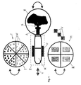
- Fig. 2 shows an articulated arm robot R in vertical Assignment to a test table T with individual segments W, each handle G to have. It can be seen that the segments W have a relatively small identification field on the circumference have as disk D. As soon as this with its segment W in the Control or measuring position has entered, the program step triggered thereby begins. At the end of the turntable moves to its next position.
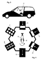
- Fig. 3 it can be seen that the robot R is conveniently in place in a car the removed driver's seat can be installed on the vehicle floor, what the test in the vehicle interior is the optimal positioning. So you can all electromechanical tests and measurements from Perform haptics, temperature, currents, rigidity, etc., but also test bench and Make control settings.
- Fig. 4 shows the arrangement of e.g. robot R pivotable in the direction of the arrow a slide guide H in the center of a hexagon test center with six stations can accommodate different test objects.
- Schematic and without limitation on these specific examples in Fig. 4 are a center console B, a cup holder C, a Group of cockpit control panels E, a turn signal lever system N, an air conditioning control device arrangement P and a group of door modules U drawn.
- One is particularly suitable for online product control in series production Test cell as shown schematically in Fig. 5.
- the measuring table M preferably has a transfer device Y, which is a coupling station KS (left in Fig. 5) is assigned to the supply and discharge of material.
- Robot R can use a 6-axis articulated robot that is controlled by the ST from (right in Fig. 5) controllable and with a gripper changing station and more suitable Sensor technology is equipped. In this way, test items 1, 2, 3, 4, 5 etc. can be control as conveniently as reliably.
- test cell product control is automated directly in the manufacturing process.
- the coupling station KS recognizes the test object from the coding of the tool carrier can then drive into a control station.
- the robot adapts depending on the task R automatically the necessary gripper or sensor and controls e.g. compliance given manufacturing tolerances.
- Processes initiated, for example the return of the test specimen to the assembly line.
- a robot-based test cell can also be used for measuring, testing and adjusting the type of Fig. 6 serve. It in turn has one glazed with Makrolon panes Safety enclosure X.
- a robot R controlled by a controller ST, for example a 6-axis articulated robot.
- he adapts e.g. from one Exchange station the required gripper or sensor for testing, testing and / or adjusting a test object, such as a cup holder C.
- the test cell has one for solving the particular problem Task suitable sensors and a 3D measuring table M with holes in Standard grid of e.g. 100 mm for variable robot and test specimen recordings.
- a 3D measuring table M with holes in Standard grid of e.g. 100 mm for variable robot and test specimen recordings.
- On the X cell enclosure preferably allows two sliding doors Safety switch for safe access inside.
- the industrial PC controls it Processes in the entire test cell, documents the results and provides them Further processing ready.
- the invention is not limited to any of the described embodiments and applications limited, but can be modified and used in a variety of ways.
- the system and the process steps associated with it are not just in development of operating devices and elements is extremely useful, for example for pre-series and Test series, but also for example in environmental simulation in climate chambers, in quality assurance and in the overall vehicle analysis.
- Test sequences can be designed flexibly, because from the continuous analysis of operator-dependent forces, torques, hysteresis switching points etc.. based on the electrical signal reactions and effects the further course of the examination follows. If a robot comes along from the outside Linear rail or retracted into a vehicle using a lifting station, so it can are based on specified calibration points and even independently actuation positions Find. The short set-up times are exceptional in production and assembly advantageous because it increases the availability and reusability of Robots can be increased very easily, which leads directly to cost reductions.
- Robot movements during their course depend on location, position and movement Functions on selected bodies K and surfaces F, which can be used for measuring, testing or Arranges handling purposes within reach of a robot R, with those guided by him or sensors S assigned to it can be measured or scanned in order to digitize Store measured values in particular in a computer (PC) and / or directly in the Control of robot movements.
- the robot R in question leads one sensor S each on programmed measuring curves, each robot station point RB [x (t), y (t), z (t)] at the same time assigned to a sensor measurement value or measurement field [SM (t)] selected operating functions on the bodies K and surfaces F.
- the measured values or fields [SM (t)] can be logged, for example, by PC programs, can be analyzed and / or - preferably in real time - to the robot controller transferable, especially via a real-time kernel interface.
Abstract
Description
- Fig. 1
- eine schematische Draufsicht auf eine Roboteranordnung mit drei Modulfeldern,
- Fig. 2
- eine Schrägansicht eines Prüftisches mit Meßroboter,
- Fig. 2a
- eine Schrägdraufsicht auf zwei Prüftisch-Segmente,
- Fig. 3
- eine schematische Darstellung der Anordnung eines Roboters in einem Kraftfahrzeug,
- Fig. 4
- eine schematische Draufsicht auf einen Roboter im Zentrum von Modultischen,
- Fig. 5
- eine schematische Seitenansicht einer Prüfzelle für On-Line-Produktkontrolle und
- Fig. 6
- eine schematische Seitenansicht einer anderen Prüfzelle.
- A
- Roboter-Arm
- B
- Mittelkonsole
- C
- Cupholder
- D
- Datenträger
- E
- Cockpit-Bedienfelder
- F
- Flächen
- G
- Griffe
- H
- Schlittenführung
- K
- Körper
- L
- Längsrichtung
- M
- Meßplattform / Meßtisch
- N
- Blinkerhebelsystem
- P
- Klimabediengeräte
- PC
- Computer
- R
- Roboter
- RB
- Roboterbahn
- S
- Sensoren
- SM
- Sensor-Meßwerk / -Meßfelder
- ST
- Controller
- T
- Prüftisch
- U
- Türmodule
- V
- Vorratsstation
- W
- Segmente
- X
- Einhausung
- Y
- Transfereinrichtung
- Z
- Grundplatte
- I, II, III
- Modultische / Stationen
Claims (18)
- System zum Erfassen, Beeinflussen und Ausnutzen von Roboterbewegungen, womit während ihres Ablaufs orts-, lage- und bewegungsabhängige Funktionen an ausgewählten Körpern und Flächen, die in Reichweite eines Roboters angeordnet sind, mit von diesem geführten Sensoren meßbar sind und womit die Meßwerte in digitalisierter Form insbesondere in einem Computer speicherbar und/oder in die Steuerung der Roboterbewegungen einbringbar sind.
- System nach Anspruch 1, gekennzeichnet durch Ausführbarkeit und Auswertung der Messungen in Echtzeit.
- System nach Anspruch 1 oder 2, dadurch gekennzeichnet, daß an den Körpern und Flächen ausgewählte Bedienfunktionen einleitbar sind, worauf während ihres Ablaufs Bedienkräfte und -momente in Abhängigkeit von Betätigungswegen und -winkeln mit den robotergeführten oder -zugeordneten Sensoren meßbar und/oder überwachbar sind, z.B. mittels einer Kamera.
- System nach einem der Ansprüche 1 bis 3, dadurch gekennzeichnet, daß mit dem bzw. jedem Roboter ein aufgenommener Sensor auf programmierter Meßkurve führbar ist, wobei die Roboterbahn RB [x(t), y(t), z(t)] gleichzeitig jeweils Sensor-Meßwerten oder -Meßfeldern [SM (t)] zugeordnet ist.
- System nach einem der Ansprüche 1 bis 4, dadurch gekennzeichnet, daß auf oder in Roboter-Armen mehrachsige Kräfte- und Momentensensoren und/oder Lasersensoren lösbar angebracht sind.
- System nach einem der Ansprüche 1 bis 5, dadurch gekennzeichnet, daß die Meßwerte bzw. Meßfelder [SM (t)] mit PC-Programmen protokollierbar und/oder analysierbar sind.
- System nach Anspruch 6, dadurch gekennzeichnet, daß die protokollierten Meßwerte bzw. Meßfelder [SM (t)] in Echtzeit an die Robotersteuerung übertragbar sind.
- System nach Anspruch 7, dadurch gekennzeichnet, daß zur Meßprotokoll-Übertragung ein Real-Time-Kernel-Interface, ein Netzwerkanschluß, eine parallele Schnittstelle o.dgl. vorhanden ist.
- System nach einem der Ansprüche 1 bis 8, dadurch gekennzeichnet, daß gleichartige Mittel und Hilfsmittel sowohl in der Entwicklung als auch in der Produktkontrolle einsetzbar sind, namentlich on-line.
- System nach einem der Ansprüche 1 bis 9, dadurch gekennzeichnet, daß der bzw. jeder Roboter in einem Fahrzeug, auf oder neben einem Prüftisch, einer Meßplattform u.dgl. fixierbar ist.
- System nach einem der Ansprüche 1 bis 10, dadurch gekennzeichnet, daß wenigstens ein Prüftisch (T), eine Meßplattform (M), eine Grundplatte (Z) o.dgl. vorhanden ist und daß programmierte Prüftisch- und/oder Roboter-Positionen durch PC-gesteuerte Regelung anlaufbar sind.
- System nach Anspruch 11, dadurch gekennzeichnet, daß ein kreisrund begrenzter Prüftisch (T) vorhanden ist, der spitzwinkelige, einzeln einsetz- und entnehmbare Segmente (W) aufweist.
- System nach Anspruch 12, dadurch gekennzeichnet, daß zumindest vorbestimmte Segmente (W) jeweils mit einem berührungslos abtastbaren Datenträger (D) versehen sind, der Speicherinformationen für automatisch einleitbare Meßvorgänge enthält.
- System nach einem der Ansprüche 10 bis 13, dadurch gekennzeichnet, daß der Prüftisch (T) schrittweise durch einen Servo-Direktantrieb verfahrund/oder verdrehbar ist, der eine Knickarmroboter-Achse bildet oder ihr zugeordnet ist.
- System nach einem der Ansprüche 10 bis 14, dadurch gekennzeichnet, daß der Roboter (R) auf oder neben einem Prüftisch, einer Meßplattform u.dgl. montierbar ist, bedarfsweise in einem Labor, einer Klimakammer, einer Produktions-Roboterzelle, einem Fahrzeug o.dgl.
- System nach Anspruch 15, dadurch gekennzeichnet, daß zumindest ein Roboter (R) in einem Fahrzeug namentlich auf dem Fahrzeugboden an der Stelle des Fahrer- oder Beifahrersitzes montierbar ist.
- System nach einem der Ansprüche 1 bis 16, dadurch gekennzeichnet, daß drei Modultische oder Stationen (I, II, III) innerhalb der Reichweite wenigstens eines Roboters (R) angeordnet sind, vorzugsweise in einer Stern-Gruppierung.
- System nach Anspruch 17, dadurch gekennzeichnet, daß der bzw. jeder Roboter (R) zwischen oder neben zwei Modultischen bzw. -stationen (I, III) angeordnet und insbesondere linear verfahrbar ist.
Priority Applications (1)
| Application Number | Priority Date | Filing Date | Title |
|---|---|---|---|
| EP03009654.9A EP1473123B1 (de) | 2003-04-30 | 2003-04-30 | System zum Erfassen, Beeinflussen und Ausnutzen von Roboterbewegungen |
Applications Claiming Priority (1)
| Application Number | Priority Date | Filing Date | Title |
|---|---|---|---|
| EP03009654.9A EP1473123B1 (de) | 2003-04-30 | 2003-04-30 | System zum Erfassen, Beeinflussen und Ausnutzen von Roboterbewegungen |
Publications (2)
| Publication Number | Publication Date |
|---|---|
| EP1473123A1 true EP1473123A1 (de) | 2004-11-03 |
| EP1473123B1 EP1473123B1 (de) | 2018-06-06 |
Family
ID=32981780
Family Applications (1)
| Application Number | Title | Priority Date | Filing Date |
|---|---|---|---|
| EP03009654.9A Expired - Lifetime EP1473123B1 (de) | 2003-04-30 | 2003-04-30 | System zum Erfassen, Beeinflussen und Ausnutzen von Roboterbewegungen |
Country Status (1)
| Country | Link |
|---|---|
| EP (1) | EP1473123B1 (de) |
Cited By (10)
| Publication number | Priority date | Publication date | Assignee | Title |
|---|---|---|---|---|
| DE102006006246A1 (de) * | 2006-02-10 | 2007-08-16 | Battenberg, Günther | Verfahren und Vorrichtung zur vollautomatischen Endkontrolle von Bauteilen und/oder deren Funktionseinheiten |
| WO2010085546A1 (en) | 2009-01-21 | 2010-07-29 | Highres Biosolutions | Instrument turntable and method for use |
| EP2322897A1 (de) | 2009-11-11 | 2011-05-18 | Günther Battenberg | Optisches und mechanisches Verfahren und Vorrichtung zum Vermessen von Werkstücken |
| WO2016066616A1 (de) * | 2014-10-27 | 2016-05-06 | Kuka Systems Gmbh | Verfahren und robotersystem zur nutzung eines industrieroboters für prüfaufgaben |
| CN106625780A (zh) * | 2017-01-19 | 2017-05-10 | 长安大学 | 一种足式仿生机器人姿态控制测试平台及测试方法 |
| CN107421755A (zh) * | 2017-08-11 | 2017-12-01 | 中汽研(天津)汽车工程研究院有限公司 | 一种汽车综合测量平台 |
| DE102012209317B4 (de) | 2012-06-01 | 2018-05-24 | Eberspächer Exhaust Technology GmbH & Co. KG | Abgasanlagenfertigungsstätte zum Fertigen von Abgasanlagen für Brennkraftmaschinen |
| DE102018202115A1 (de) * | 2018-02-12 | 2019-08-14 | Volkswagen Aktiengesellschaft | Robotermodul, Typspezifische Bodenplatte sowie Verfahren zum Ausführen von Arbeiten in einem Fahrzeuginnenraum bei der Fertigung eines Fahrzeugs an einem Fließband |
| CN113665841A (zh) * | 2021-07-27 | 2021-11-19 | 中航西安飞机工业集团股份有限公司 | 基于协作机器人的飞机驾驶舱方向盘操纵测试方法 |
| US11583999B2 (en) | 2020-10-05 | 2023-02-21 | Ford Global Technologies, Llc | Method and system for operating a transfer robot in a manufacturing environment |
Citations (9)
| Publication number | Priority date | Publication date | Assignee | Title |
|---|---|---|---|---|
| US4621332A (en) * | 1983-06-20 | 1986-11-04 | Hitachi, Ltd. | Method and apparatus for controlling a robot utilizing force, position, velocity, spring constant, mass coefficient, and viscosity coefficient |
| DE3627560C2 (de) | 1986-08-14 | 1988-11-17 | Audi Ag, 8070 Ingolstadt, De | |
| US4836742A (en) * | 1984-03-14 | 1989-06-06 | Toyota Jidosha Kabushiki Kaisha | System for controlling a robot in association with a rotary table |
| EP0336342A2 (de) * | 1988-04-01 | 1989-10-11 | Toyota Jidosha Kabushiki Kaisha | Echtzeitsteuersystem für einen industriellen Roboter zum Folgen eines Standardweges |
| US5125149A (en) * | 1989-04-28 | 1992-06-30 | Canon Kabushiki Kaisha | Method of accessing and assembling parts in an assembly apparatus incorporating mobile robots |
| US5386762A (en) * | 1992-09-14 | 1995-02-07 | Gokey; Phillip E. | Robotic chef |
| US5959425A (en) * | 1998-10-15 | 1999-09-28 | Fanuc Robotics North America, Inc. | Vision guided automatic robotic path teaching method |
| DE20003381U1 (de) | 2000-02-24 | 2001-07-05 | Kuka Schweissanlagen Gmbh | Prüfeinrichtung für bewegliche optische Messeinrichtungen |
| EP1202041A1 (de) * | 2000-10-31 | 2002-05-02 | Ford Global Technologies, Inc. | Verfahren und Vorrichtung zur Belastungsprüfung von elektrischen Systemen eines Kraftfahrzeugs |
-
2003
- 2003-04-30 EP EP03009654.9A patent/EP1473123B1/de not_active Expired - Lifetime
Patent Citations (9)
| Publication number | Priority date | Publication date | Assignee | Title |
|---|---|---|---|---|
| US4621332A (en) * | 1983-06-20 | 1986-11-04 | Hitachi, Ltd. | Method and apparatus for controlling a robot utilizing force, position, velocity, spring constant, mass coefficient, and viscosity coefficient |
| US4836742A (en) * | 1984-03-14 | 1989-06-06 | Toyota Jidosha Kabushiki Kaisha | System for controlling a robot in association with a rotary table |
| DE3627560C2 (de) | 1986-08-14 | 1988-11-17 | Audi Ag, 8070 Ingolstadt, De | |
| EP0336342A2 (de) * | 1988-04-01 | 1989-10-11 | Toyota Jidosha Kabushiki Kaisha | Echtzeitsteuersystem für einen industriellen Roboter zum Folgen eines Standardweges |
| US5125149A (en) * | 1989-04-28 | 1992-06-30 | Canon Kabushiki Kaisha | Method of accessing and assembling parts in an assembly apparatus incorporating mobile robots |
| US5386762A (en) * | 1992-09-14 | 1995-02-07 | Gokey; Phillip E. | Robotic chef |
| US5959425A (en) * | 1998-10-15 | 1999-09-28 | Fanuc Robotics North America, Inc. | Vision guided automatic robotic path teaching method |
| DE20003381U1 (de) | 2000-02-24 | 2001-07-05 | Kuka Schweissanlagen Gmbh | Prüfeinrichtung für bewegliche optische Messeinrichtungen |
| EP1202041A1 (de) * | 2000-10-31 | 2002-05-02 | Ford Global Technologies, Inc. | Verfahren und Vorrichtung zur Belastungsprüfung von elektrischen Systemen eines Kraftfahrzeugs |
Cited By (18)
| Publication number | Priority date | Publication date | Assignee | Title |
|---|---|---|---|---|
| DE102006006246A1 (de) * | 2006-02-10 | 2007-08-16 | Battenberg, Günther | Verfahren und Vorrichtung zur vollautomatischen Endkontrolle von Bauteilen und/oder deren Funktionseinheiten |
| WO2007090672A2 (de) * | 2006-02-10 | 2007-08-16 | Battenberg Guenther | Verfahren und vorrichtung zur vollautomatischen endkontrolle von bauteilen und/oder deren funktionseinheiten |
| WO2007090672A3 (de) * | 2006-02-10 | 2008-02-21 | Guenther Battenberg | Verfahren und vorrichtung zur vollautomatischen endkontrolle von bauteilen und/oder deren funktionseinheiten |
| EP2098933A1 (de) * | 2006-02-10 | 2009-09-09 | Günther Battenberg | Verfahren und Vorrichtung zur vollautomatischen Endkontrolle von Bauteilen und/oder deren Funktionseinheiten |
| EP2111953A1 (de) * | 2006-02-10 | 2009-10-28 | Günther Battenberg | System umfassend einen Roboter mit mindestens einem Lagesensor und mindestens einer Prüfvorrichtung |
| EP2389590A4 (de) * | 2009-01-21 | 2013-09-11 | Highres Biosolutions | Instrumentendrehtisch und verfahren zu seiner verwendung |
| EP2389590A1 (de) * | 2009-01-21 | 2011-11-30 | Highres Biosolutions | Instrumentendrehtisch und verfahren zu seiner verwendung |
| WO2010085546A1 (en) | 2009-01-21 | 2010-07-29 | Highres Biosolutions | Instrument turntable and method for use |
| EP2322897A1 (de) | 2009-11-11 | 2011-05-18 | Günther Battenberg | Optisches und mechanisches Verfahren und Vorrichtung zum Vermessen von Werkstücken |
| DE102012209317B4 (de) | 2012-06-01 | 2018-05-24 | Eberspächer Exhaust Technology GmbH & Co. KG | Abgasanlagenfertigungsstätte zum Fertigen von Abgasanlagen für Brennkraftmaschinen |
| WO2016066616A1 (de) * | 2014-10-27 | 2016-05-06 | Kuka Systems Gmbh | Verfahren und robotersystem zur nutzung eines industrieroboters für prüfaufgaben |
| CN106625780A (zh) * | 2017-01-19 | 2017-05-10 | 长安大学 | 一种足式仿生机器人姿态控制测试平台及测试方法 |
| CN106625780B (zh) * | 2017-01-19 | 2023-05-30 | 长安大学 | 一种足式仿生机器人姿态控制测试平台及测试方法 |
| CN107421755A (zh) * | 2017-08-11 | 2017-12-01 | 中汽研(天津)汽车工程研究院有限公司 | 一种汽车综合测量平台 |
| DE102018202115A1 (de) * | 2018-02-12 | 2019-08-14 | Volkswagen Aktiengesellschaft | Robotermodul, Typspezifische Bodenplatte sowie Verfahren zum Ausführen von Arbeiten in einem Fahrzeuginnenraum bei der Fertigung eines Fahrzeugs an einem Fließband |
| US11583999B2 (en) | 2020-10-05 | 2023-02-21 | Ford Global Technologies, Llc | Method and system for operating a transfer robot in a manufacturing environment |
| CN113665841A (zh) * | 2021-07-27 | 2021-11-19 | 中航西安飞机工业集团股份有限公司 | 基于协作机器人的飞机驾驶舱方向盘操纵测试方法 |
| CN113665841B (zh) * | 2021-07-27 | 2023-09-05 | 中航西安飞机工业集团股份有限公司 | 基于协作机器人的飞机驾驶舱方向盘操纵测试方法 |
Also Published As
| Publication number | Publication date |
|---|---|
| EP1473123B1 (de) | 2018-06-06 |
Similar Documents
| Publication | Publication Date | Title |
|---|---|---|
| DE102016004841B4 (de) | Verfahren und Vorrichtung zum Festlegen eines Bewegungsablaufs für einen Roboter | |
| Yamada et al. | Proposal of skill-assist: A system of assisting human workers by reflecting their skills in positioning tasks | |
| DE102016002812A1 (de) | Robotersystem, Verfahren zur Steuerung eines Robotersystems und Fließbearbeitungsvorrichtung | |
| EP1473123B1 (de) | System zum Erfassen, Beeinflussen und Ausnutzen von Roboterbewegungen | |
| DE202013105036U1 (de) | Erfassungseinrichtung | |
| DE102016114776A1 (de) | Werkteil-Haltevorrichtung, Montagesystem und Verfahren zum Platzieren und Festhalten eines Werkteils | |
| EP2392435A2 (de) | Werkzeug-Handhabungssystem und Verfahren zum Manipulieren von Werkstücken mittels kooperierender Manipulatoren | |
| DE102008062622A1 (de) | Verfahren und Vorrichtung zur Befehlseingabe in eine Steuerung eines Manipulators | |
| DE3627560C3 (de) | Programmgesteuerte und sensorgeführte Fertigungs- und/oder Montageeinheit, insbesondere Industrieroboter | |
| DE102019103557B4 (de) | Schwingungsanalysator und Schwingungsanalyseverfahren | |
| DE102007037077A1 (de) | Verfahren zur Einhaltung von Arbeitsraumgrenzen eines Arbeitsmittels eines Roboters | |
| EP1187700B1 (de) | Positioniervorrichtung für werkstückträger oder werkstücke | |
| DE3045094A1 (de) | Programmierbarer manipulator | |
| WO2019101908A1 (de) | Modularer endeffektor | |
| DE102015117458B4 (de) | Verfahren zur Reinigung einer Befestigungsfläche für ein Ausgleichselement an einem Fahrzeugrad | |
| DE3710688A1 (de) | Roboterfuehrbares werkzeug | |
| DE102012022190A1 (de) | Inverse Kinematik | |
| DE102016124892B4 (de) | Bearbeitungsvorrichtung mit einer programmtechnischen Steuerung | |
| EP3717187B1 (de) | Stanzbearbeitungsstation und verfahren zur fixierung eines mit einer lackierung versehenen polymeren kfz-stossfängers während eines stanzvorganges | |
| DE20321782U1 (de) | Robotersystem | |
| WO2015049136A2 (de) | Arbeitsvorrichtung und arbeitsverfahren | |
| EP3448623B1 (de) | Montagevorrichtung, verfahren zur steuerung der montagevorrichtung und verfahren zum herstellen in einer montagevorrichtung | |
| DE102016204258A1 (de) | Vorrichtung und Verfahren zum automatisierten Greifen und Handhaben von Werkstücken | |
| DE102019102798A1 (de) | Kombinieren zweier einzelner Robotermanipulatoren zu einem Robotersystem durch Kalibrieren | |
| EP1074338B1 (de) | Werkzeugmaschinenführungssystem bzw. Mehrachsenroboter für eine Mehrzahl von Werkzeugen |
Legal Events
| Date | Code | Title | Description |
|---|---|---|---|
| PUAI | Public reference made under article 153(3) epc to a published international application that has entered the european phase |
Free format text: ORIGINAL CODE: 0009012 |
|
| AK | Designated contracting states |
Kind code of ref document: A1 Designated state(s): AT BE BG CH CY CZ DE DK EE ES FI FR GB GR HU IE IT LI LU MC NL PT RO SE SI SK TR |
|
| AX | Request for extension of the european patent |
Extension state: AL LT LV MK |
|
| 17P | Request for examination filed |
Effective date: 20050503 |
|
| AKX | Designation fees paid |
Designated state(s): AT BE BG CH CY CZ DE DK EE ES FI FR GB GR HU IE IT LI LU MC NL PT RO SE SI SK TR |
|
| AXX | Extension fees paid |
Extension state: LV Payment date: 20050503 Extension state: AL Payment date: 20050503 Extension state: LT Payment date: 20050503 Extension state: MK Payment date: 20050503 |
|
| 17Q | First examination report despatched |
Effective date: 20081125 |
|
| GRAP | Despatch of communication of intention to grant a patent |
Free format text: ORIGINAL CODE: EPIDOSNIGR1 |
|
| STAA | Information on the status of an ep patent application or granted ep patent |
Free format text: STATUS: GRANT OF PATENT IS INTENDED |
|
| INTG | Intention to grant announced |
Effective date: 20171130 |
|
| GRAS | Grant fee paid |
Free format text: ORIGINAL CODE: EPIDOSNIGR3 |
|
| GRAA | (expected) grant |
Free format text: ORIGINAL CODE: 0009210 |
|
| STAA | Information on the status of an ep patent application or granted ep patent |
Free format text: STATUS: THE PATENT HAS BEEN GRANTED |
|
| AK | Designated contracting states |
Kind code of ref document: B1 Designated state(s): AT BE BG CH CY CZ DE DK EE ES FI FR GB GR HU IE IT LI LU MC NL PT RO SE SI SK TR |
|
| AX | Request for extension of the european patent |
Extension state: AL LT LV MK |
|
| REG | Reference to a national code |
Ref country code: GB Ref legal event code: FG4D Free format text: NOT ENGLISH |
|
| REG | Reference to a national code |
Ref country code: CH Ref legal event code: EP Ref country code: AT Ref legal event code: REF Ref document number: 1005543 Country of ref document: AT Kind code of ref document: T Effective date: 20180615 |
|
| REG | Reference to a national code |
Ref country code: IE Ref legal event code: FG4D Free format text: LANGUAGE OF EP DOCUMENT: GERMAN |
|
| REG | Reference to a national code |
Ref country code: DE Ref legal event code: R096 Ref document number: 50315759 Country of ref document: DE |
|
| REG | Reference to a national code |
Ref country code: RO Ref legal event code: EPE |
|
| REG | Reference to a national code |
Ref country code: NL Ref legal event code: MP Effective date: 20180606 |
|
| REG | Reference to a national code |
Ref country code: LT Ref legal event code: MG9D |
|
| PG25 | Lapsed in a contracting state [announced via postgrant information from national office to epo] |
Ref country code: ES Free format text: LAPSE BECAUSE OF FAILURE TO SUBMIT A TRANSLATION OF THE DESCRIPTION OR TO PAY THE FEE WITHIN THE PRESCRIBED TIME-LIMIT Effective date: 20180606 Ref country code: SE Free format text: LAPSE BECAUSE OF FAILURE TO SUBMIT A TRANSLATION OF THE DESCRIPTION OR TO PAY THE FEE WITHIN THE PRESCRIBED TIME-LIMIT Effective date: 20180606 Ref country code: FI Free format text: LAPSE BECAUSE OF FAILURE TO SUBMIT A TRANSLATION OF THE DESCRIPTION OR TO PAY THE FEE WITHIN THE PRESCRIBED TIME-LIMIT Effective date: 20180606 Ref country code: CY Free format text: LAPSE BECAUSE OF FAILURE TO SUBMIT A TRANSLATION OF THE DESCRIPTION OR TO PAY THE FEE WITHIN THE PRESCRIBED TIME-LIMIT Effective date: 20180606 |
|
| PG25 | Lapsed in a contracting state [announced via postgrant information from national office to epo] |
Ref country code: GR Free format text: LAPSE BECAUSE OF FAILURE TO SUBMIT A TRANSLATION OF THE DESCRIPTION OR TO PAY THE FEE WITHIN THE PRESCRIBED TIME-LIMIT Effective date: 20180907 |
|
| REG | Reference to a national code |
Ref country code: SK Ref legal event code: T3 Ref document number: E 28355 Country of ref document: SK |
|
| PG25 | Lapsed in a contracting state [announced via postgrant information from national office to epo] |
Ref country code: NL Free format text: LAPSE BECAUSE OF FAILURE TO SUBMIT A TRANSLATION OF THE DESCRIPTION OR TO PAY THE FEE WITHIN THE PRESCRIBED TIME-LIMIT Effective date: 20180606 |
|
| PG25 | Lapsed in a contracting state [announced via postgrant information from national office to epo] |
Ref country code: EE Free format text: LAPSE BECAUSE OF FAILURE TO SUBMIT A TRANSLATION OF THE DESCRIPTION OR TO PAY THE FEE WITHIN THE PRESCRIBED TIME-LIMIT Effective date: 20180606 |
|
| PG25 | Lapsed in a contracting state [announced via postgrant information from national office to epo] |
Ref country code: IT Free format text: LAPSE BECAUSE OF FAILURE TO SUBMIT A TRANSLATION OF THE DESCRIPTION OR TO PAY THE FEE WITHIN THE PRESCRIBED TIME-LIMIT Effective date: 20180606 |
|
| REG | Reference to a national code |
Ref country code: DE Ref legal event code: R097 Ref document number: 50315759 Country of ref document: DE |
|
| PLBE | No opposition filed within time limit |
Free format text: ORIGINAL CODE: 0009261 |
|
| STAA | Information on the status of an ep patent application or granted ep patent |
Free format text: STATUS: NO OPPOSITION FILED WITHIN TIME LIMIT |
|
| 26N | No opposition filed |
Effective date: 20190307 |
|
| PG25 | Lapsed in a contracting state [announced via postgrant information from national office to epo] |
Ref country code: DK Free format text: LAPSE BECAUSE OF FAILURE TO SUBMIT A TRANSLATION OF THE DESCRIPTION OR TO PAY THE FEE WITHIN THE PRESCRIBED TIME-LIMIT Effective date: 20180606 Ref country code: SI Free format text: LAPSE BECAUSE OF FAILURE TO SUBMIT A TRANSLATION OF THE DESCRIPTION OR TO PAY THE FEE WITHIN THE PRESCRIBED TIME-LIMIT Effective date: 20180606 |
|
| REG | Reference to a national code |
Ref country code: CH Ref legal event code: PL |
|
| REG | Reference to a national code |
Ref country code: BE Ref legal event code: MM Effective date: 20190430 |
|
| GBPC | Gb: european patent ceased through non-payment of renewal fee |
Effective date: 20190430 |
|
| PG25 | Lapsed in a contracting state [announced via postgrant information from national office to epo] |
Ref country code: LU Free format text: LAPSE BECAUSE OF NON-PAYMENT OF DUE FEES Effective date: 20190430 Ref country code: MC Free format text: LAPSE BECAUSE OF FAILURE TO SUBMIT A TRANSLATION OF THE DESCRIPTION OR TO PAY THE FEE WITHIN THE PRESCRIBED TIME-LIMIT Effective date: 20180606 |
|
| REG | Reference to a national code |
Ref country code: SK Ref legal event code: MM4A Ref document number: E 28355 Country of ref document: SK Effective date: 20190430 |
|
| PG25 | Lapsed in a contracting state [announced via postgrant information from national office to epo] |
Ref country code: LI Free format text: LAPSE BECAUSE OF NON-PAYMENT OF DUE FEES Effective date: 20190430 Ref country code: SK Free format text: LAPSE BECAUSE OF NON-PAYMENT OF DUE FEES Effective date: 20190430 Ref country code: GB Free format text: LAPSE BECAUSE OF NON-PAYMENT OF DUE FEES Effective date: 20190430 Ref country code: CH Free format text: LAPSE BECAUSE OF NON-PAYMENT OF DUE FEES Effective date: 20190430 Ref country code: CZ Free format text: LAPSE BECAUSE OF NON-PAYMENT OF DUE FEES Effective date: 20190430 Ref country code: BG Free format text: LAPSE BECAUSE OF NON-PAYMENT OF DUE FEES Effective date: 20191031 Ref country code: RO Free format text: LAPSE BECAUSE OF NON-PAYMENT OF DUE FEES Effective date: 20180606 |
|
| PG25 | Lapsed in a contracting state [announced via postgrant information from national office to epo] |
Ref country code: BE Free format text: LAPSE BECAUSE OF NON-PAYMENT OF DUE FEES Effective date: 20190430 |
|
| PG25 | Lapsed in a contracting state [announced via postgrant information from national office to epo] |
Ref country code: TR Free format text: LAPSE BECAUSE OF FAILURE TO SUBMIT A TRANSLATION OF THE DESCRIPTION OR TO PAY THE FEE WITHIN THE PRESCRIBED TIME-LIMIT Effective date: 20180606 |
|
| PG25 | Lapsed in a contracting state [announced via postgrant information from national office to epo] |
Ref country code: IE Free format text: LAPSE BECAUSE OF NON-PAYMENT OF DUE FEES Effective date: 20190430 |
|
| PG25 | Lapsed in a contracting state [announced via postgrant information from national office to epo] |
Ref country code: FR Free format text: LAPSE BECAUSE OF NON-PAYMENT OF DUE FEES Effective date: 20190430 Ref country code: PT Free format text: LAPSE BECAUSE OF FAILURE TO SUBMIT A TRANSLATION OF THE DESCRIPTION OR TO PAY THE FEE WITHIN THE PRESCRIBED TIME-LIMIT Effective date: 20181008 |
|
| PGFP | Annual fee paid to national office [announced via postgrant information from national office to epo] |
Ref country code: DE Payment date: 20200428 Year of fee payment: 18 |
|
| REG | Reference to a national code |
Ref country code: AT Ref legal event code: MM01 Ref document number: 1005543 Country of ref document: AT Kind code of ref document: T Effective date: 20190430 |
|
| PG25 | Lapsed in a contracting state [announced via postgrant information from national office to epo] |
Ref country code: AT Free format text: LAPSE BECAUSE OF NON-PAYMENT OF DUE FEES Effective date: 20190430 |
|
| PG25 | Lapsed in a contracting state [announced via postgrant information from national office to epo] |
Ref country code: HU Free format text: LAPSE BECAUSE OF FAILURE TO SUBMIT A TRANSLATION OF THE DESCRIPTION OR TO PAY THE FEE WITHIN THE PRESCRIBED TIME-LIMIT; INVALID AB INITIO Effective date: 20030430 |
|
| REG | Reference to a national code |
Ref country code: DE Ref legal event code: R119 Ref document number: 50315759 Country of ref document: DE |
|
| PG25 | Lapsed in a contracting state [announced via postgrant information from national office to epo] |
Ref country code: DE Free format text: LAPSE BECAUSE OF NON-PAYMENT OF DUE FEES Effective date: 20211103 |