EP1473052A2 - Medical device having releasable retainer - Google Patents
Medical device having releasable retainer Download PDFInfo
- Publication number
- EP1473052A2 EP1473052A2 EP04009922A EP04009922A EP1473052A2 EP 1473052 A2 EP1473052 A2 EP 1473052A2 EP 04009922 A EP04009922 A EP 04009922A EP 04009922 A EP04009922 A EP 04009922A EP 1473052 A2 EP1473052 A2 EP 1473052A2
- Authority
- EP
- European Patent Office
- Prior art keywords
- hub
- needle
- distal end
- tip
- retaining element
- Prior art date
- Legal status (The legal status is an assumption and is not a legal conclusion. Google has not performed a legal analysis and makes no representation as to the accuracy of the status listed.)
- Granted
Links
Images


Classifications
-
- A—HUMAN NECESSITIES
- A61—MEDICAL OR VETERINARY SCIENCE; HYGIENE
- A61M—DEVICES FOR INTRODUCING MEDIA INTO, OR ONTO, THE BODY; DEVICES FOR TRANSDUCING BODY MEDIA OR FOR TAKING MEDIA FROM THE BODY; DEVICES FOR PRODUCING OR ENDING SLEEP OR STUPOR
- A61M5/00—Devices for bringing media into the body in a subcutaneous, intra-vascular or intramuscular way; Accessories therefor, e.g. filling or cleaning devices, arm-rests
- A61M5/178—Syringes
- A61M5/31—Details
- A61M5/32—Needles; Details of needles pertaining to their connection with syringe or hub; Accessories for bringing the needle into, or holding the needle on, the body; Devices for protection of needles
- A61M5/34—Constructions for connecting the needle, e.g. to syringe nozzle or needle hub
- A61M5/346—Constructions for connecting the needle, e.g. to syringe nozzle or needle hub friction fit
-
- E—FIXED CONSTRUCTIONS
- E01—CONSTRUCTION OF ROADS, RAILWAYS, OR BRIDGES
- E01D—CONSTRUCTION OF BRIDGES, ELEVATED ROADWAYS OR VIADUCTS; ASSEMBLY OF BRIDGES
- E01D22/00—Methods or apparatus for repairing or strengthening existing bridges ; Methods or apparatus for dismantling bridges
-
- A—HUMAN NECESSITIES
- A61—MEDICAL OR VETERINARY SCIENCE; HYGIENE
- A61M—DEVICES FOR INTRODUCING MEDIA INTO, OR ONTO, THE BODY; DEVICES FOR TRANSDUCING BODY MEDIA OR FOR TAKING MEDIA FROM THE BODY; DEVICES FOR PRODUCING OR ENDING SLEEP OR STUPOR
- A61M5/00—Devices for bringing media into the body in a subcutaneous, intra-vascular or intramuscular way; Accessories therefor, e.g. filling or cleaning devices, arm-rests
- A61M5/178—Syringes
- A61M5/31—Details
- A61M5/32—Needles; Details of needles pertaining to their connection with syringe or hub; Accessories for bringing the needle into, or holding the needle on, the body; Devices for protection of needles
- A61M5/3205—Apparatus for removing or disposing of used needles or syringes, e.g. containers; Means for protection against accidental injuries from used needles
- A61M5/321—Means for protection against accidental injuries by used needles
- A61M5/3216—Caps placed transversally onto the needle, e.g. pivotally attached to the needle base
-
- E—FIXED CONSTRUCTIONS
- E01—CONSTRUCTION OF ROADS, RAILWAYS, OR BRIDGES
- E01D—CONSTRUCTION OF BRIDGES, ELEVATED ROADWAYS OR VIADUCTS; ASSEMBLY OF BRIDGES
- E01D2/00—Bridges characterised by the cross-section of their bearing spanning structure
- E01D2/02—Bridges characterised by the cross-section of their bearing spanning structure of the I-girder type
-
- A—HUMAN NECESSITIES
- A61—MEDICAL OR VETERINARY SCIENCE; HYGIENE
- A61B—DIAGNOSIS; SURGERY; IDENTIFICATION
- A61B17/00—Surgical instruments, devices or methods, e.g. tourniquets
- A61B17/20—Surgical instruments, devices or methods, e.g. tourniquets for vaccinating or cleaning the skin previous to the vaccination
- A61B17/205—Vaccinating by means of needles or other puncturing devices
-
- A—HUMAN NECESSITIES
- A61—MEDICAL OR VETERINARY SCIENCE; HYGIENE
- A61M—DEVICES FOR INTRODUCING MEDIA INTO, OR ONTO, THE BODY; DEVICES FOR TRANSDUCING BODY MEDIA OR FOR TAKING MEDIA FROM THE BODY; DEVICES FOR PRODUCING OR ENDING SLEEP OR STUPOR
- A61M5/00—Devices for bringing media into the body in a subcutaneous, intra-vascular or intramuscular way; Accessories therefor, e.g. filling or cleaning devices, arm-rests
- A61M5/178—Syringes
- A61M5/31—Details
- A61M5/32—Needles; Details of needles pertaining to their connection with syringe or hub; Accessories for bringing the needle into, or holding the needle on, the body; Devices for protection of needles
- A61M5/3205—Apparatus for removing or disposing of used needles or syringes, e.g. containers; Means for protection against accidental injuries from used needles
- A61M5/321—Means for protection against accidental injuries by used needles
- A61M5/3243—Means for protection against accidental injuries by used needles being axially-extensible, e.g. protective sleeves coaxially slidable on the syringe barrel
- A61M5/3269—Means for protection against accidental injuries by used needles being axially-extensible, e.g. protective sleeves coaxially slidable on the syringe barrel guided by means not coaxially aligned with syringe barrel, e.g. channel-like member formed on exterior surface of syringe barrel for guiding a pushing rod connected to and displacing needle safety sheath
-
- A—HUMAN NECESSITIES
- A61—MEDICAL OR VETERINARY SCIENCE; HYGIENE
- A61M—DEVICES FOR INTRODUCING MEDIA INTO, OR ONTO, THE BODY; DEVICES FOR TRANSDUCING BODY MEDIA OR FOR TAKING MEDIA FROM THE BODY; DEVICES FOR PRODUCING OR ENDING SLEEP OR STUPOR
- A61M5/00—Devices for bringing media into the body in a subcutaneous, intra-vascular or intramuscular way; Accessories therefor, e.g. filling or cleaning devices, arm-rests
- A61M5/178—Syringes
- A61M5/31—Details
- A61M5/32—Needles; Details of needles pertaining to their connection with syringe or hub; Accessories for bringing the needle into, or holding the needle on, the body; Devices for protection of needles
- A61M5/3205—Apparatus for removing or disposing of used needles or syringes, e.g. containers; Means for protection against accidental injuries from used needles
- A61M5/321—Means for protection against accidental injuries by used needles
- A61M5/3243—Means for protection against accidental injuries by used needles being axially-extensible, e.g. protective sleeves coaxially slidable on the syringe barrel
- A61M5/3275—Means for protection against accidental injuries by used needles being axially-extensible, e.g. protective sleeves coaxially slidable on the syringe barrel being connected to the needle hub or syringe by radially deflectable members, e.g. longitudinal slats, cords or bands
-
- A—HUMAN NECESSITIES
- A61—MEDICAL OR VETERINARY SCIENCE; HYGIENE
- A61M—DEVICES FOR INTRODUCING MEDIA INTO, OR ONTO, THE BODY; DEVICES FOR TRANSDUCING BODY MEDIA OR FOR TAKING MEDIA FROM THE BODY; DEVICES FOR PRODUCING OR ENDING SLEEP OR STUPOR
- A61M5/00—Devices for bringing media into the body in a subcutaneous, intra-vascular or intramuscular way; Accessories therefor, e.g. filling or cleaning devices, arm-rests
- A61M5/178—Syringes
- A61M5/31—Details
- A61M5/32—Needles; Details of needles pertaining to their connection with syringe or hub; Accessories for bringing the needle into, or holding the needle on, the body; Devices for protection of needles
- A61M5/34—Constructions for connecting the needle, e.g. to syringe nozzle or needle hub
- A61M5/347—Constructions for connecting the needle, e.g. to syringe nozzle or needle hub rotatable, e.g. bayonet or screw
-
- E—FIXED CONSTRUCTIONS
- E01—CONSTRUCTION OF ROADS, RAILWAYS, OR BRIDGES
- E01D—CONSTRUCTION OF BRIDGES, ELEVATED ROADWAYS OR VIADUCTS; ASSEMBLY OF BRIDGES
- E01D2101/00—Material constitution of bridges
- E01D2101/20—Concrete, stone or stone-like material
- E01D2101/24—Concrete
- E01D2101/26—Concrete reinforced
- E01D2101/268—Composite concrete-metal
-
- Y—GENERAL TAGGING OF NEW TECHNOLOGICAL DEVELOPMENTS; GENERAL TAGGING OF CROSS-SECTIONAL TECHNOLOGIES SPANNING OVER SEVERAL SECTIONS OF THE IPC; TECHNICAL SUBJECTS COVERED BY FORMER USPC CROSS-REFERENCE ART COLLECTIONS [XRACs] AND DIGESTS
- Y10—TECHNICAL SUBJECTS COVERED BY FORMER USPC
- Y10S—TECHNICAL SUBJECTS COVERED BY FORMER USPC CROSS-REFERENCE ART COLLECTIONS [XRACs] AND DIGESTS
- Y10S604/00—Surgery
- Y10S604/905—Aseptic connectors or couplings, e.g. frangible, piercable
Definitions
- the present invention relates to a medical device such as a hypodermic needle assembly which is adapted to releasably engage a fluid transfer device such as a syringe.
- a medical device such as a hypodermic needle assembly having a releasable retaining element for improving the connection between a needle assembly and a syringe.
- a hypodermic syringe consists of a cylindrical barrel, most commonly made of thermoplastic material or glass, with a distal end adapted to be connected to a hypodermic needle and a proximal end adapted to receive a stopper and plunger rod assembly.
- the stopper provides a relatively air-tight seal between itself and the syringe barrel so that movement of the stopper up and down the barrel will cause liquid, blood or other fluids to be drawn into or forced out of the syringe through the distal end.
- the stopper is moved along the syringe barrel by applying axial force on a rigid plunger rod which is connected to the stopper and is sufficiently long to be accessible outside of the barrel.
- Hypodermic needle assemblies typically including a cannula and a hub, are often removably attached to syringes for performing a variety of tasks such as the delivery of medication into patients and into devices, and for withdrawing fluid samples from patients and from fluid sources.
- the hub of the hypodermic needle assembly has tapered interior surface adapted to engage the tapered tip of the syringe barrel so that the two components are joined in a frictional interference fit.
- the tapered syringe tip and the complementarily tapered receptacle in the hub are referred to as standard luer fittings.
- a wide variety of other medical devices such as stopcocks and tubing sets have standard luer fittings which allow them to be engaged to a syringe tip.
- the frictional fit between the syringe tip and the needle hub or other medical device is strong enough to prevent accidental disengagement caused by the fluid pressures within the syringe and/or other factors such as forces applied to the needle hub when actuating safety needle shields connected to the hub. If the syringe tip becomes disengaged from the needle assembly, medication, blood or other fluids will be lost, and there is also potential for contamination.
- the prior art teaches many structures for improving the connection between medical devices having tapered luer fittings such as needle assemblies and syringes. These structures include complementary engaging structure on both the needle hub and syringe barrel tip such as projections and recess providing for a snap-fit arrangement. Manually releasable locking structures are provided to increase the connection between the needle hub and barrel tip while allowing reasonable forces for disconnections of these components. Also, enhancements to the luer tip of the syringe barrel such as coatings, sandblasting and mechanical collars have provided for improved connection between a needle hub and a syringe barrel tip. Many of the structures taught by the prior art do not contemplate the subsequent removal of the needle assembly from the syringe barrel.
- the medical device having a releasable retainer of the present invention for use with a fluid transfer device having a frusto-conically shaped tip includes a hub having an open proximal end with a frusto-conically shaped cavity therein, a distal end and a passageway therethrough. The cavity is part of the passageway.
- a retaining element is releasably connected to the hub.
- the retaining element includes an aperture therein and at least one protuberance projecting into the aperture for engaging the frusto-conically shaped tip of the fluid transfer device.
- the protuberance is shaped to offer less resistance to hub movement in a direction of engagement than in a direction of disengagement with the tip.
- the hub may also include a needle cannula having a proximal end, a sharp distal end and a lumen therethrough.
- the needle cannula is joined to the distal end of the hub so that the lumen in the cannula is in fluid communication with the passageway in the hub.
- the retaining element may include a plurality of protuberances on the retaining elements.
- the structure for connecting the retaining element to the hub may include a wide variety of interference fits or structures or additional elements including, but not limited to, frangible links and adhesive.
- the protuberance can extend for 360° around the retaining element.
- the retaining element need not extend completely around the passageway of the hub.
- the needle assembly may include a pivotable needle shield having a cavity therein hingedly connected to the hub and capable of pivoting from a needle exposing position which allows access to the distal end of the needle cannula and a needle protecting position wherein the distal end of the needle cannula is within the cavity of the needle shield.
- the medical device may be connected to a syringe barrel having an inside surface defining a chamber, an open proximal end and a distal end including an elongate frusto-conically shaped tip having a conduit therethrough.
- the needle assembly is connected to the syringe barrel so that the frusto-conically shaped tip is in fluid-tight engagement with the frusto-conically shaped cavity of the hub and the lumen is in fluid communication with the cavity.
- Another alternative embodiment of the needle assembly of the present invention further includes a guide element on the hub having an aperture therethrough.
- An elongate barrier arm having a proximal end and a distal end is positioned in the aperture for sliding axial movement therein.
- the distal end of the barrier arm includes a barrier element having a distal end, a proximal end and a needle passageway therethrough.
- the needle cannula is positioned at least partially within the needle passageway of the barrier element.
- the barrier arm is movable from at least a first retracted position wherein the distal end of the needle cannula passes completely through the barrier element so that the distal end of the needle cannula is exposed, to a second extended position wherein the barrier element surrounds the distal end of the needle cannula to prevent incidental contact with the distal end of the needle cannula.
- a finger contact surface on the barrier arm is provided to accept digital force to the barrier arm to move the barrier arm into the second extended position.
- Still another alternative embodiment of the needle assembly of the present invention further includes a needle guard having a proximal end, a distal end and a needle passageway therethrough.
- the needle guard is movable along the needle cannula from a first position substantially adjacent the proximal end of the needle cannula to a second position where a distal tip of the needle cannula is intermediate the opposed proximal and distal ends of the needle guard.
- a hinged arm having proximal and distal segments articulated to one another for movement between a first position wherein the segments are substantially collapsed onto one another and a second position where the segments are extended from one another is provided.
- the proximal segment of the hinged arm is articulated to a portion of the hub.
- the distal segment of the hinged arm is articulated to the needle guard.
- the proximal and distal segments of the hinged arm have respective lengths for permitting the guard to move from the first position to the second position on the needle cannula and for preventing the guard from moving distally beyond the second position.
- the components of the hinged arm may be integrally molded of thermoplastic material.
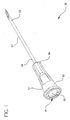
- Fig. 1 is a perspective view of a needle assembly of the present invention.
- Fig. 2 is an exploded perspective view of the needle assembly of Fig. 1.
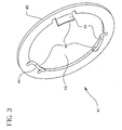
- Fig. 3 is a perspective view of the retaining element of the needle assembly.
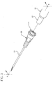
- Fig. 4 is a partial cross-sectional perspective view of the needle assembly.
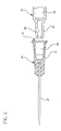
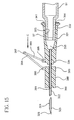
- Fig. 5 is an exploded perspective view illustrating the needle assembly and a syringe barrel having a frusto-conically shaped tip.
- Fig. 6 is a partial cross-sectional view of the needle assembly and syringe barrel of Fig. 5 taken along line 6-6.
- Fig. 7 illustrates the needle assembly and syringe barrel of Fig. 6 connected so that the lumen of the needle is in fluid communication with the chamber of the barrel.
- Fig. 8 is a perspective view of the distal end of the syringe barrel with retaining element attached thereto.
- Fig. 9 is a partial cross-sectional view illustrating the needle assembly of the present invention attached to a syringe barrel having a locking luer collar.
- Fig. 10 illustrates an alternative embodiment of the needle assembly of the present invention having a pivotable needle shield.
- Fig. 11 is an enlarged cross-sectional view of the syringe barrel and needle assembly of Fig. 10 taken along line 11-11.
- Fig. 12 is a perspective view of an alternative embodiment of the needle assembly of the present invention illustrated after frictional engagement with a syringe barrel tip.
- Fig. 13 is a cross-sectional view of the needle assembly and syringe barrel of Fig. 12 taken along line 13-13.
- Fig. 14 is a perspective view of another alterative embodiment of the needle assembly of the present invention illustrated after frictional engagement with a syringe barrel tip.
- Fig. 15 is a cross-sectional view of the needle assembly and syringe barrel of Fig. 14 taken along line 15-15.
- Fig. 16 is a perspective view of another alternative needle assembly of the present invention.
- Fig. 17 is an enlarged cross-sectional view of the needle assembly of Fig. 16 taken along line 17-17.
- a medical device such as needle assembly 20 includes a needle cannula 21 having a proximal end 22, a distal end 23 and a lumen 24 therethrough defining a longitudinal axis 25 .
- a hub 31 includes an open proximal end 32 with a cavity 33 therein, a distal end 34 and a passageway 35 therethrough. The cavity is part of the passageway.
- the proximal end of the needle cannula is joined to the distal end of the hub so that the lumen of the needle cannula is in fluid communication with the passageway of the hub.
- hub 31 may include radial projections 37 for engaging the locking-type collar of a syringe barrel or other fluid-delivery device.
- Needle cannula 21 is preferably made of metal such as stainless steel and can be held to the hub using various manufacturing methods with adhesives such as epoxy being preferred.
- the hub is preferably made of injection moldable plastic such as polypropylene, polyethylene, polycarbonate and combinations thereof.
- the needle cannula and hub may be integrally formed of thermoplastic material.
- the needle assembly can be used with a variety of fluid transfer devices having a frusto-conically shaped luer tip such as a hypodermic syringe.
- a syringe includes syringe barrel 51 having an inside surface 52 defining a chamber 53, an open proximal end 55 and a distal end 56 including an elongate frusto-conically shaped tip 57 having a conduit 58 therethrough.
- the needle assembly is connected to the syringe barrel so that the frusto-conically shaped tip is in fluid-tight engagement with the frusto-conically shaped cavity in the hub and the lumen is in fluid communication with the cavity.
- a concern with prior art needle assemblies and syringe barrels having complementary luer fittings is that the needle assembly may become loosened or disengaged from the syringe tip during use.
- any liquid medication inadvertently deposited on the barrel tip can change the frictional properties of the tip and increase the potential for unintended disengagement of the needle assembly.
- the present invention provides a medical device having a fluid transfer fitting, such as a needle hub, which can be used with any standard luer slip fitting to provide improved retention of the needle assembly to the luer slip fitting and to allow for more uniform removal force as will be explained in detail hereinafter.
- a fluid transfer fitting such as a needle hub
- This improvement is accomplished through the use of retaining element 41 which is releasably connected to hub 31 .
- Retaining element 41 includes aperture 43 therein and at least one protuberance 44 projecting into the aperture for engaging the frusto-conically shaped tip of a syringe barrel for up to 360° of the aperture.
- the retaining element need not extend entirely around the cavity and it can be a discrete single element.
- the term "aperture" as used herein can include an opening or cut-out.
- the protuberance is shaped to offer less resistance to hub movement in a direction of engagement than in a direction of disengagement from a luer slip fitting such as a barrel tip.
- the directional bias is accomplished by distally and inwardly facing end 45 of protuberance 44 .
- the distally-facing end portions of the protuberance will allow the needle assembly to be connected to the barrel tip with application of forces which are comparable to those using a hub without a retaining element.
- the end of the protuberance which deflects slightly upon installation of the needle assembly, tends to engage the needle hub to prevent unintended disengagement of the needle assembly during use.
- Various materials and protuberance shapes can be used to form a retaining element so long as the force of engagement of the retaining element to the barrel tip is less than the force required to remove the retaining element from the barrel tip.
- An important feature of the present invention lies in the fact that there can be a substantial difference between the engagement force of the retaining element and the force required to dislodge the retaining element since the force required to remove the needle assembly from the barrel tip is controlled by means for connecting the retaining element to the hub.
- the force required to disconnect the retaining element from the hub is controlled by an interference fit between outside diameter 46 of the retaining element and inside diameter 38 of recess 39 in the hub.
- the retaining element is desirably made of metal which is preferably stainless steel.
- the retaining element is formed from stainless steel sheet metal. It can be seen that the outside diameter of the retaining element could be formed in a fully or partial cylindrical shape to provide increased surface contact between the retaining element and the hub.
- interference or “interference fit” used to describe the connection between the retaining element and the hub is intended to include any manner of press-fit, snap-fit and variations thereof where the retaining element must overcome a physical engagement with the hub to release therefrom.
- Means for connecting as used herein is intended to include interferences and other means such as adhesives or frangible connections between the retaining element and hub which break upon application of the desired force.
- Means for connecting may also include a retaining element which is configured to engage an outside surface of the hub so that the interference is between the element and the outside of the hub. It may also include an additional element between the retaining element and the hub. All of these variations fall within the purview of the present invention and the interference fit of the metal retaining element to the hub is merely representative of these many possibilities.
- needle assembly 20 is connected to syringe barrel 51 by placing the elongate frusto-conically shaped barrel tip into the frusto-conically shaped cavity of the needle hub and applying an axial force sufficient to frictionally engage the surface of the hub cavity and the outside surface of the barrel tip as illustrated in Fig. 7.
- the retaining element slides down the barrel tip eventually contacting the barrel tip with enough force to engage the tip and make it more difficult to move the element in a distal direction than in a proximal direction.
- the element can provide additional retaining force.
- an axially distally directed force is applied to the needle hub until the retaining element disconnects from the hub and the needle assembly is allowed to move in a distal direction.
- the retaining element remains on the barrel tip after removal of the needle hub and needle combination.
- Additional needle assemblies such as the needle assembly of the present invention or a standard needle assembly can be subsequently connected to the syringe tip having the retaining element attached thereto because the installation force will move the retaining element in a proximal direction to make room for the subsequent needle assembly to frictionally engage the barrel tip.
- a syringe barrel 151 includes an inside surface 152 defining a chamber 153 , and a distal end 156 including an elongate frusto-conically shaped tip 157 having a conduit 158 therethrough.
- the distal end of the syringe barrel also includes a locking luer-type collar 159 concentrically surrounding tip 157 of the barrel.
- the luer collar has an internal thread 160 which engages radial projections 37 on the hub to hold it securely to the barrel.
- needle assembly 120 includes a needle cannula 121 having a proximal end 122 and a distal end 123 and a hub 131 .
- Hub 131 includes an open proximal end 132 with a frusto-conically shaped cavity 133, a distal end 134 , a passageway 135 therethrough. The cavity is part of the passageway.
- the proximal end of the needle cannula is joined to the distal end of the hub so that the lumen of the needle cannula is in fluid communication with the passageway.
- a retaining element 141 is releasably connected to hub 131 .
- the retaining element includes an aperture therein and at least one protuberance projecting into the aperture for engaging the frusto-conically shaped tip 57 of the barrel.
- the protuberance is shaped to offer less resistance to hub movement in a direction of engagement than in a direction of disengagement with the barrel tip.
- the retaining element is connected to the hub so that when the hub is in fluid-tight engagement with the tip, the force required to disengage the retaining element from the tip is greater than the force required to disengage the retaining element from the hub.
- Hub 131 further includes pivotable needle shield 161 which is hingedly connected to the hub and capable of pivoting from a needle exposing position, as illustrated in Figs.
- axel 163 rotatably engages axel housing 164 on the hub.
- the user pivots the needle shield into the needle protecting position by applying digital force to the needle shield.
- Such force has at least a component in direction A as illustrated in Fig. 10.
- the present invention is especially useful as a hinged needle shield needle assembly.
- Force A is another force which may contribute to the unintentional disconnection of the needle assembly from the barrel which is resisted by action of the retaining elements' engagement to the barrel tip.
- needle assembly 220 includes a needle cannula 221 having a proximal end 222 , a distal end 223 and a lumen therethrough.
- a hub 231 includes an open proximal end 232 with a frusto-conically shaped cavity 233 therein, a distal end 234 and a passageway 235 therethrough. The cavity is part of the passageway.
- the proximal end of the needle cannula is joined to the distal end of the hub so that the lumen is in fluid communication with the passageway.
- a retaining element 241 is releasably connected to the hub.
- the retaining element has at least one protuberance 244 for engaging frusto-conically shaped tip 57 of syringe barrel 51 .
- the protuberance is shaped to offer less resistance to hub movement in a direction of engagement with the syringe barrel tip than in a direction of disengagement with the tip.
- the retaining element of this embodiment functions substantially similarly to retaining element 41 of the embodiments of Figs. 1-8.
- Hub 231 further includes a guide element 276 having an aperture 277 therethrough.
- An elongate barrier arm 279 having a proximal end 280 and a distal end 281 includes a barrier element 282 on distal end 281 .
- the barrier element includes a proximal end 283 , a distal end 285 and a needle passageway 286 therethrough.
- the barrier arm is positioned within the aperture of the guide element and the needle cannula is positioned at least partially within the needle passageway of the barrier element.
- the barrier element is movable from at least a first retracted position, illustrated in Figs. 12-13, wherein the distal end of the needle cannula passes completely through the barrier element so that the distal end of the needle cannula is exposed, to a second extended position (not illustrated) wherein the barrier element surrounds the distal end of the needle cannula to prevent incidental contact with tip 226 on the distal end of the needle cannula.
- a finger contact surface 287 on the barrier arm is provided for applying digital force to the barrier arm to move the barrier arm into the second extended position. This is accomplished by applying a digital force to the finger contact surface having at least a component in direction B as illustrated in Fig. 13.
- the aperture in the guide element can be any shape, closed or open, which works cooperatively to guide the barrier arm between the first retracted position and the second extended position.
- the barrier arm may be curved or the aperture in the guide element angled so that the needle passageway misaligns with tip 326 on the needle cannula to help prevent movement of the barrier element from the second extended position.
- needle assembly 320 includes a needle cannula 321 having a proximal end 322, a distal end 323 and a hub 331.
- Hub 331 includes an open proximal end 332 with a frusto-conically shaped cavity 333 , a distal end 334 and a passageway 335 therethrough. The cavity is part of the passageway.
- the proximal end of the needle cannula is joined to the distal end of the hub so that the lumen of the needle cannula is in fluid communication with the passageway.
- a retaining element 341 is releasably connected to the hub.
- Retaining element includes at least one protuberance 344 for engaging frusto-conically shaped tip 57 of syringe barrel 51.
- Retaining element 341 functions similarly to retaining element 41 in the embodiment of Figs. 1-8.
- Needle assembly 320 further includes a needle guard 388 having a proximal end 389, a distal end 390 and a needle passageway 391 therethrough. The needle guard is movable along the needle cannula from a first position substantially adjacent to the proximal end of the needle cannula as illustrated in Figs. 14-15, to a second position where the distal tip 326 of the needle cannula is intermediate the opposed proximal and distal ends of needle guard 388 .
- a hinged arm 392 having a proximal segment 393 and a distal segment 394 which are articulated to one another for movement between a first position where the segments are substantially collapsed onto one another, as illustrated in Figs. 14-15, to a second position where the segments are extended from one another.
- the proximal segment of the hinged arm is articulated to a portion of the hub through a structure that allows such movement, such as hinged 395 in this embodiment.
- the distal segment of the hinged arm is articulated to needle guard 388 through hinge 396.
- Proximal segment 393 and distal segment 394 are articulated with respect to each other through hinge 397.
- the proximal and distal segments of the hinged arm have respective lengths for permitting the needle guard to move from the first position to the second position on the needle cannula and for preventing the guard from moving distally beyond the second position.
- the needle guard is moved to the second position through application of a digital force having at least a component in direction C as illustrated in Fig. 15.
- the hinges may be mechanical hinges or linkages or flexible connections such as living hinges.
- needle assembly 420 includes a needle 421 having a proximal end 422, a distal end 423 and a hub 431.
- Hub 431 includes an open proximal end 432 with a frusto-conically shaped cavity 433 , a distal end 434 and a passageway 435 therethrough. The cavity is part of the passageway.
- the proximal end of the needle is joined to the distal end of the hub so that the needle projects distally outwardly from the distal end of the hub.
- a retaining element 441 is releasably connected to the hub.
- Retaining element 441 includes at least one protuberance 444 for engaging a frusto-conically shaped tip of a fluid delivery device such as a syringe barrel.
- Release element 441 functions similarly to release element 41 in the embodiment of Figs. 1-8.
- Needle 421 does not have a functioning lumen and in this embodiment, has a bifurcated distal tip 426 .
- Solid needles such as the needle having a bifurcated tip are commonly used for administering vaccines, antigens, and other substances to the skin.
- the bifurcated tip is used to scratch or slightly pierce the skin of the patient so that the liquid substance, such as a vaccine, may be absorbed into the skin of the patient.
- the needle assembly of this embodiment can be attached to a syringe barrel, wherein the syringe barrel is used as a handle to control and guide the needle tip during the vaccination process.
Landscapes
- Health & Medical Sciences (AREA)
- Engineering & Computer Science (AREA)
- Public Health (AREA)
- Veterinary Medicine (AREA)
- Biomedical Technology (AREA)
- Heart & Thoracic Surgery (AREA)
- Hematology (AREA)
- Life Sciences & Earth Sciences (AREA)
- Animal Behavior & Ethology (AREA)
- General Health & Medical Sciences (AREA)
- Vascular Medicine (AREA)
- Anesthesiology (AREA)
- Environmental & Geological Engineering (AREA)
- Architecture (AREA)
- Civil Engineering (AREA)
- Structural Engineering (AREA)
- Infusion, Injection, And Reservoir Apparatuses (AREA)
- Media Introduction/Drainage Providing Device (AREA)
- Electrotherapy Devices (AREA)
- Measuring Pulse, Heart Rate, Blood Pressure Or Blood Flow (AREA)
- Measuring And Recording Apparatus For Diagnosis (AREA)
- External Artificial Organs (AREA)
Abstract
Description
Claims (14)
- A medical device for use with a fluid transfer device having a frusto-conically shaped tip comprising:a hub having an open proximal end with a frusto-conically-shaped cavity therein, a distal end and a passageway therethrough, said cavity being part of said passageway; and,a retaining element releasably connected to said hub, said element having an aperture therein and at least one protuberance projecting into said aperture for engaging said frusto-conically shaped tip, said protuberance being shaped to offer less resistance to hub movement in a direction of engagement than in a direction of disengagement with said tip, means for connecting said retaining element to said hub so that when said hub is in fluid-tight engagement with said tip, the force required to disengage said retaining element from said tip is greater than the force required to disengage said retaining element from said hub.
- The medical device of Claim 1 further including an elongate needle having a proximal end and a distal end, said proximal end of said needle being joined to said distal end of said hub.
- The medical device of Claim I wherein said at least one protuberance is three protuberances spaced around said aperture.
- The medical device of Claim I wherein said retaining element is positioned at a proximal end of said cavity in said hub.
- The medical device of Claim 1 wherein said means for connecting is an interference fit between said retaining element and said hub.
- The medical device of Claim 1 wherein said retaining element completely surrounds said passageway.
- The medical device of Claim 1 wherein said retaining element is made of metal.
- The medical device of Claim 1 wherein said hub is made of thermoplastic material.
- The medical device of Claim 2 wherein said hub includes a pivotable needle shield having a cavity therein hingedly connected to said hub and capable of pivoting from a needle exposing position which allows access to said distal end of said needle cannula and a needle protecting position wherein said distal end of said needle cannula is within the cavity of said needle shield.
- The medical device of Claim 2 further comprising:a guide element on said hub having an aperture therethrough;an elongate barrier arm having a proximal end and a distal end, said distal end of said barrier arm including a barrier element having a distal end, a proximal end and a needle passageway therethrough, said barrier arm positioned within said aperture of said guide element and said needle cannula positioned at least partially within said needle passageway of said barrier element, said barrier arm being movable from at least a first retracted position wherein said distal end of said needle cannula passes completely through said barrier element so that said distal end of said needle cannula is exposed, to a second extended position wherein said barrier element surrounds said distal end of said cannula to prevent incidental contact with said distal end of said needle cannula; andfinger contact surface on said barrier arm for applying digital force to said barrier arm to move said barrier arm into said second extended position.
- The medical device of Claim 2 further comprising:a needle guard having a proximal end, a distal end and a needle passageway therethrough, said needle guard being movable along said needle cannula from a first position substantially adjacent said proximal end of said needle cannula to a second position where distal tip of said distal end of said needle cannula is intermediate said opposed proximal and distal ends of said needle guard;a hinged arm having proximal and distal segments articulated to one another for movement between a first position where said segments are substantially collapsed onto one another and a second position where said segments are extended from one another, said proximal segment of said hinged arm being articulated to a portion of said hub, said distal segment of said hinged arm being articulated to said guard, said proximal and distal segments of said hinged arm having respective lengths for permitting said guard to move from said first position to said second position on said needle cannula, and for preventing said guard from moving distally beyond said second position.
- The medical device of Claim 2 further including a syringe barrel having an inside surface defining a chamber, an open proximal end and a distal end including an elongate frusto-conically shaped tip having a conduit therethrough, said needle assembly being connected to said syringe barrel so that said frusto-conically shaped tip is in fluid-tight engagement with said frusto-conically shaped cavity of said hub and said lumen is in fluid communication with said cavity.
- A needle assembly for use with a fluid transfer device having a frusto-conically shaped tip comprising:a needle cannula having a proximal end, a sharp distal end and a lumen therethrough;a hub having an open proximal end with a frusto-conically shaped cavity therein, a distal end and a passageway therethrough, said cavity being part of said passageway, said proximal end of said needle cannula being connected to said distal end of said hub so that said lumen is in fluid communication with said passageway; anda metal retaining element releasably connected to said hub at a proximal end of said cavity, said element having an aperture therein and a plurality of protuberances projecting into said aperture for engaging said frusto-conically shaped tip, said protuberances being shaped to offer less resistance to hub movement in a direction of engagement than in a direction of disengagement with said tip, said retaining element and said hub being configured to be held together by an interference fit so that when said hub is in fluid-tight engagement with said tip, the force required to disengage said retaining element from said tip is greater than the force required to disengage the retaining element from said hub.
- The needle assembly of Claim 13 further including a syringe barrel having an inside surface defining a chamber, an open proximal end and a distal end including an elongate frusto-conically shaped tip having a conduit therethrough, said.needle assembly being connected to said syringe barrel so that said frusto-conically shaped tip is in fluid-tight engagement with said frusto-conically shaped cavity of said hub and said lumen is in fluid communication with said cavity.
Applications Claiming Priority (2)
| Application Number | Priority Date | Filing Date | Title |
|---|---|---|---|
| US428648 | 2003-05-02 | ||
| US10/428,648 US7115114B2 (en) | 2003-05-02 | 2003-05-02 | Medical device having releasable retainer |
Publications (3)
| Publication Number | Publication Date |
|---|---|
| EP1473052A2 true EP1473052A2 (en) | 2004-11-03 |
| EP1473052A3 EP1473052A3 (en) | 2006-12-06 |
| EP1473052B1 EP1473052B1 (en) | 2009-06-17 |
Family
ID=32990486
Family Applications (1)
| Application Number | Title | Priority Date | Filing Date |
|---|---|---|---|
| EP04009922A Expired - Lifetime EP1473052B1 (en) | 2003-05-02 | 2004-04-27 | Medical device having releasable retainer |
Country Status (15)
| Country | Link |
|---|---|
| US (2) | US7115114B2 (en) |
| EP (1) | EP1473052B1 (en) |
| JP (1) | JP4478498B2 (en) |
| KR (1) | KR101068250B1 (en) |
| CN (2) | CN1550240A (en) |
| AT (1) | ATE433770T1 (en) |
| BR (1) | BRPI0401510B1 (en) |
| CA (1) | CA2464854C (en) |
| DE (1) | DE602004021530D1 (en) |
| DK (1) | DK1473052T3 (en) |
| ES (1) | ES2327733T3 (en) |
| MX (1) | MXPA04004048A (en) |
| NZ (1) | NZ532487A (en) |
| SG (1) | SG120156A1 (en) |
| ZA (1) | ZA200403182B (en) |
Families Citing this family (71)
| Publication number | Priority date | Publication date | Assignee | Title |
|---|---|---|---|---|
| US7115114B2 (en) * | 2003-05-02 | 2006-10-03 | Becton, Dickinson And Company | Medical device having releasable retainer |
| US7217258B2 (en) * | 2003-05-02 | 2007-05-15 | Becton, Dickinson And Company | Controlled release structure for attaching medical devices |
| JP3883527B2 (en) * | 2003-07-17 | 2007-02-21 | ニプロ株式会社 | Transfer needle |
| US7494481B2 (en) * | 2004-12-03 | 2009-02-24 | Medtronic Minimed, Inc. | Multi-position infusion set device and process |
| GB2414401B (en) | 2004-05-28 | 2009-06-17 | Cilag Ag Int | Injection device |
| GB2414399B (en) | 2004-05-28 | 2008-12-31 | Cilag Ag Int | Injection device |
| GB2414403B (en) | 2004-05-28 | 2009-01-07 | Cilag Ag Int | Injection device |
| GB2414402B (en) | 2004-05-28 | 2009-04-22 | Cilag Ag Int | Injection device |
| GB2414775B (en) | 2004-05-28 | 2008-05-21 | Cilag Ag Int | Releasable coupling and injection device |
| GB2414409B (en) | 2004-05-28 | 2009-11-18 | Cilag Ag Int | Injection device |
| GB2414406B (en) | 2004-05-28 | 2009-03-18 | Cilag Ag Int | Injection device |
| GB2414400B (en) | 2004-05-28 | 2009-01-14 | Cilag Ag Int | Injection device |
| US20060190079A1 (en) * | 2005-01-21 | 2006-08-24 | Naim Istephanous | Articulating spinal disc implants with amorphous metal elements |
| GB2425062B (en) | 2005-04-06 | 2010-07-21 | Cilag Ag Int | Injection device |
| GB2424835B (en) | 2005-04-06 | 2010-06-09 | Cilag Ag Int | Injection device (modified trigger) |
| GB2424836B (en) | 2005-04-06 | 2010-09-22 | Cilag Ag Int | Injection device (bayonet cap removal) |
| GB2427826B (en) | 2005-04-06 | 2010-08-25 | Cilag Ag Int | Injection device comprising a locking mechanism associated with integrally formed biasing means |
| GB2424838B (en) | 2005-04-06 | 2011-02-23 | Cilag Ag Int | Injection device (adaptable drive) |
| DE602005018480D1 (en) | 2005-08-30 | 2010-02-04 | Cilag Gmbh Int | Needle device for a prefilled syringe |
| US20110098656A1 (en) | 2005-09-27 | 2011-04-28 | Burnell Rosie L | Auto-injection device with needle protecting cap having outer and inner sleeves |
| US20070100296A1 (en) * | 2005-10-31 | 2007-05-03 | Becton, Dickinson And Company | Single-handedly actuatable shield for needles |
| GB2438590B (en) | 2006-06-01 | 2011-02-09 | Cilag Gmbh Int | Injection device |
| GB2438591B (en) | 2006-06-01 | 2011-07-13 | Cilag Gmbh Int | Injection device |
| GB2438593B (en) | 2006-06-01 | 2011-03-30 | Cilag Gmbh Int | Injection device (cap removal feature) |
| US7871397B2 (en) | 2006-12-26 | 2011-01-18 | Stat Medical Devices, Inc. | Pen needle tip |
| GB2461086B (en) | 2008-06-19 | 2012-12-05 | Cilag Gmbh Int | Injection device |
| GB2461087B (en) | 2008-06-19 | 2012-09-26 | Cilag Gmbh Int | Injection device |
| GB2461085B (en) | 2008-06-19 | 2012-08-29 | Cilag Gmbh Int | Injection device |
| GB2461084B (en) | 2008-06-19 | 2012-09-26 | Cilag Gmbh Int | Fluid transfer assembly |
| GB2461089B (en) | 2008-06-19 | 2012-09-19 | Cilag Gmbh Int | Injection device |
| US7850667B2 (en) * | 2008-06-27 | 2010-12-14 | Tyco Healthcare Group Lp | Low profile instrument access device |
| CA2743583C (en) * | 2008-12-02 | 2016-11-15 | Allergan, Inc. | Injection device |
| US8012132B2 (en) * | 2009-02-24 | 2011-09-06 | Becton, Dickinson And Company | Luer-snap connection and luer-snap syringe |
| US8915890B2 (en) | 2009-07-30 | 2014-12-23 | Becton, Dickinson And Company | Medical device assembly |
| US8343106B2 (en) | 2009-12-23 | 2013-01-01 | Alcon Research, Ltd. | Ophthalmic valved trocar vent |
| EP2515774B1 (en) | 2009-12-23 | 2014-03-19 | Alcon Research, Ltd. | Ophthalmic valved trocar cannula |
| WO2011085239A1 (en) * | 2010-01-08 | 2011-07-14 | Amylin Pharmaceuticals, Inc. | Hypodermic needle assembly having a transition hub for enhancing fluid dynamics and microsphere injectability |
| KR101008476B1 (en) * | 2010-10-05 | 2011-01-14 | 김정재 | The combination structure of catheter hub and connecting tube |
| US10463803B2 (en) * | 2010-11-12 | 2019-11-05 | Stat Medical Devices, Inc. | Pen needle with quick release and/or removal system |
| CN203494005U (en) * | 2011-02-09 | 2014-03-26 | 贝克顿·迪金森公司 | One-piece catheter and transfusion system |
| USD755371S1 (en) * | 2012-04-09 | 2016-05-03 | Becton, Dickinson And Company | Needle hub for medical syringe |
| USD752214S1 (en) * | 2012-04-09 | 2016-03-22 | Becton, Dickinson And Company | Needle hub for medical syringe |
| WO2014162583A1 (en) | 2013-04-05 | 2014-10-09 | テルモ株式会社 | Injection needle assembly and drug injection device |
| US20140350518A1 (en) | 2013-05-23 | 2014-11-27 | Allergan, Inc. | Syringe extrusion accessory |
| GB2517896B (en) | 2013-06-11 | 2015-07-08 | Cilag Gmbh Int | Injection device |
| GB2515038A (en) | 2013-06-11 | 2014-12-17 | Cilag Gmbh Int | Injection device |
| GB2515032A (en) | 2013-06-11 | 2014-12-17 | Cilag Gmbh Int | Guide for an injection device |
| GB2515039B (en) | 2013-06-11 | 2015-05-27 | Cilag Gmbh Int | Injection Device |
| KR101365780B1 (en) * | 2013-06-27 | 2014-02-20 | 문정희 | Hub contact type filter cap for syringe |
| US10118000B2 (en) | 2014-04-21 | 2018-11-06 | Stat Medical Devices, Inc. | Pen needle installation and removal safety cover and pen needle assembly utilizing the same |
| US10029048B2 (en) | 2014-05-13 | 2018-07-24 | Allergan, Inc. | High force injection devices |
| US10155091B2 (en) | 2014-07-11 | 2018-12-18 | Stat Medical Devices, Inc. | Pen needle tip and method of making and using the same |
| WO2016021552A1 (en) * | 2014-08-06 | 2016-02-11 | テルモ株式会社 | Medical instrument, injection needle assembly, and drug injection apparatus |
| US10226585B2 (en) | 2014-10-01 | 2019-03-12 | Allergan, Inc. | Devices for injection and dosing |
| BR112017019272A2 (en) | 2015-03-10 | 2018-05-02 | Allergan Pharmaceuticals Holdings Ireland Unlimited Company | multiple needle injector |
| USD765838S1 (en) | 2015-03-26 | 2016-09-06 | Tech Group Europe Limited | Syringe retention clip |
| CA3020146A1 (en) | 2016-04-08 | 2017-10-12 | Allergan, Inc. | Aspiration and injection device |
| JP6302990B2 (en) * | 2016-12-21 | 2018-03-28 | テルモ株式会社 | Connecting member |
| US20180272074A1 (en) * | 2017-03-24 | 2018-09-27 | Te-Peng HUANG | Needle protector and syringe having the same |
| USD867582S1 (en) | 2017-03-24 | 2019-11-19 | Allergan, Inc. | Syringe device |
| CN107952168A (en) * | 2017-12-22 | 2018-04-24 | 天津哈娜好医材有限公司 | Lock ring type screwed union and its application method |
| CN108272528A (en) * | 2018-02-26 | 2018-07-13 | 李鲲鹏 | A kind of animal immune injection external member |
| USD876619S1 (en) * | 2018-03-06 | 2020-02-25 | Jasperate, Inc. | Hollow needle |
| CN108420464A (en) * | 2018-03-26 | 2018-08-21 | 中山大学附属第医院 | Sampling device for biopsy |
| USD878551S1 (en) * | 2018-07-23 | 2020-03-17 | Milestone Scientific, Inc. | Injection device |
| USD888235S1 (en) * | 2018-08-31 | 2020-06-23 | Devicor Medical Products, Inc. | Tip protector |
| CN109771005B (en) * | 2019-01-18 | 2020-09-25 | 首都医科大学附属北京佑安医院 | Central venous trocar with multiple holes |
| KR102371545B1 (en) * | 2019-08-21 | 2022-03-07 | (주) 레보메드 | Bone marrow harvesting device |
| CN112933344B (en) * | 2021-01-27 | 2023-04-25 | 桂林市中西医结合医院 | Injection device |
| CN117835949A (en) * | 2021-08-12 | 2024-04-05 | 贝克顿·迪金森公司 | Syringe adapter with needle hub |
| CN117180556A (en) * | 2023-08-25 | 2023-12-08 | 上海新耀湃科医疗科技股份有限公司 | Protective prefilled syringe |
Citations (1)
| Publication number | Priority date | Publication date | Assignee | Title |
|---|---|---|---|---|
| US4369781A (en) | 1981-02-11 | 1983-01-25 | Sherwood Medical Industries Inc. | Luer connector |
Family Cites Families (57)
| Publication number | Priority date | Publication date | Assignee | Title |
|---|---|---|---|---|
| US791802A (en) | 1904-05-16 | 1905-06-06 | Justin De Lisle | Hypodermic syringe. |
| US1591762A (en) | 1926-04-03 | 1926-07-06 | Faichney Instr Corp | Fastener for needle mounts |
| US1683349A (en) * | 1926-10-04 | 1928-09-04 | George N Hein | Hypodermic syringe and means for retaining same |
| US1683350A (en) | 1926-10-04 | 1928-09-04 | George N Hein | Lock for hypodermic needles and the like |
| US2034294A (en) | 1934-04-27 | 1936-03-17 | George N Hein | Needle syringe equipment |
| US2020111A (en) | 1934-06-16 | 1935-11-05 | Eisele Logan | Detachable locking means for hypodermic syringe needles |
| US2088338A (en) | 1935-03-06 | 1937-07-27 | Isidor A Popper | Hypodermic needle and novel hub for the same |
| US2764978A (en) | 1953-11-13 | 1956-10-02 | S & R J Everett & Co Ltd | Locking device for hypodermic needles |
| US2902995A (en) | 1954-10-11 | 1959-09-08 | Abbott Lab | Hypodermic syringe and needle hub structure |
| US2834346A (en) | 1955-06-06 | 1958-05-13 | Becton Dickinson Co | Syringe and hub locking assembly |
| US2828743A (en) | 1957-06-17 | 1958-04-01 | American Home Prod | Snap-on cartridge-needle unit |
| US3043304A (en) | 1959-03-30 | 1962-07-10 | Brunswick Corp | Hypodermic needle mount |
| US3472227A (en) | 1965-08-18 | 1969-10-14 | Burron Medical Prod Inc | Hypodermic needle |
| US3469581A (en) | 1967-10-23 | 1969-09-30 | Burron Medical Prod Inc | Syringe and needle adapter assembly |
| US3527217A (en) | 1968-01-18 | 1970-09-08 | William A Gettig | Hypodermic hub |
| US4040421A (en) | 1975-04-04 | 1977-08-09 | Becton, Dickinson And Company | Hypodermic syringe and attached needle assembly |
| AT360139B (en) | 1978-10-16 | 1980-12-29 | Immuno Ag | COMBINED AMPOULE DISPOSABLE INJECTION SYRINGE |
| US4430080A (en) | 1982-06-09 | 1984-02-07 | Becton, Dickinson And Company | Syringe assembly with snap-fit components |
| US4676530A (en) * | 1983-04-07 | 1987-06-30 | Warner-Lambert Company | Coupling assembly for use in fluid flow systems |
| US4490142A (en) | 1983-08-22 | 1984-12-25 | Silvern Rubin D | Carpule syringe with rapidly acting mechanism for controllably _positively retaining the hub of a hypodermic needle |
| US4589871A (en) | 1985-03-29 | 1986-05-20 | Becton, Dickinson And Company | Syringe barrel |
| US4675020A (en) | 1985-10-09 | 1987-06-23 | Kendall Mcgaw Laboratories, Inc. | Connector |
| US4747839A (en) | 1986-12-17 | 1988-05-31 | Survival Technology, Inc. | Disposable hypodermic syringe with plastic snap-on needle hub and heat shrink seal therefor |
| US4822343A (en) | 1987-09-21 | 1989-04-18 | Louise Beiser | Blood collection device with ejectable tips |
| US5066287A (en) | 1988-07-27 | 1991-11-19 | Ryan Medical, Inc. | Safety multiple sample rear adapter assembly |
| DE8805331U1 (en) * | 1988-04-22 | 1988-09-08 | Mueller, Wolfgang, Dr.Med., 2308 Preetz, De | |
| WO1991003269A1 (en) * | 1989-08-28 | 1991-03-21 | Townsend Controls Pty. Ltd. | Safety syringe |
| US5047021A (en) | 1989-08-29 | 1991-09-10 | Utterberg David S | Male luer lock medical fitting |
| US5053015A (en) | 1989-08-30 | 1991-10-01 | The Kendall Company | Locking catheter adapter |
| US5405340A (en) | 1992-10-07 | 1995-04-11 | Abbott Laboratories | Threaded securing apparatus for flow connectors |
| US5451214A (en) | 1993-03-22 | 1995-09-19 | Hajishoreh; Kaveh-Karimi | Syringe apparatus |
| US5312377A (en) | 1993-03-29 | 1994-05-17 | Dalton Michael J | Tapered luer connector |
| US5344408A (en) * | 1993-08-06 | 1994-09-06 | Becton, Dickinson And Company | Break-away safety shield for needle cannula |
| US5520657A (en) * | 1993-08-09 | 1996-05-28 | Sellers; Jackie | Method and device for vessel location cannulation utilizing a unique needle and syringe device |
| US5348544A (en) | 1993-11-24 | 1994-09-20 | Becton, Dickinson And Company | Single-handedly actuatable safety shield for needles |
| US5466223A (en) | 1994-06-20 | 1995-11-14 | Becton, Dickinson And Company | Needle assembly having single-handedly activatable needle barrier |
| US5925020A (en) * | 1994-11-22 | 1999-07-20 | Becton, Dickinson And Company | Needle point barrier |
| US5616136A (en) | 1995-01-09 | 1997-04-01 | Med-Safe Systems, Inc. | Quick release needle removal apparatus |
| US5741084A (en) * | 1995-03-27 | 1998-04-21 | Del Rio; Eddy H. | Wear compensating axial connection |
| US5713876A (en) | 1995-06-07 | 1998-02-03 | Johnson & Johnson Medical, Inc. | Catheter release mechanism |
| US5851201A (en) | 1996-01-19 | 1998-12-22 | Acacia Laboratories, Inc. | Luer connector |
| US5722643A (en) | 1996-03-07 | 1998-03-03 | Avm, Inc. | Temperature compensated safety gas spring |
| US5836919A (en) | 1996-05-23 | 1998-11-17 | Solopak Pharmaceuticals, Inc. | Cap assembly |
| US5913846A (en) * | 1996-06-13 | 1999-06-22 | Becton, Dickinson And Company | Shielded needle assembly |
| US5681295A (en) | 1996-07-03 | 1997-10-28 | Becton, Dickinson And Company | Needle shield assembly having a single-use cannula lock |
| US5672161A (en) * | 1996-09-20 | 1997-09-30 | Becton, Dickinson And Company | Needle assembly having single-handedly activated needle barrier |
| US5733265A (en) * | 1996-09-25 | 1998-03-31 | Becton Dickinson And Company | Shielded needle assembly |
| US20020072715A1 (en) * | 1998-08-28 | 2002-06-13 | Newby C. Mark | Needle assembly |
| US6132402A (en) | 1999-02-02 | 2000-10-17 | Bioform Inc. | Storage and delivery device for a catheter or needle |
| US6273715B1 (en) * | 1999-06-09 | 2001-08-14 | X-Tip Technologies, Llc | Disposable anesthesia delivery system with shortened outer sleeve and inner hollow drill |
| EP1083005A3 (en) * | 1999-08-11 | 2004-12-15 | Tah Industries, Inc. | A static mixer nozzle and attachment accessory configuration |
| US6436076B1 (en) * | 2000-12-19 | 2002-08-20 | Fu-Yu Hsu | Needle holder positioning structure for a safety syringe |
| US20020138045A1 (en) | 2001-03-20 | 2002-09-26 | Moen Michael E. | Quick connect fitting |
| AU3708902A (en) * | 2001-05-04 | 2002-11-07 | Becton Dickinson & Company | Passively activated safely needle |
| KR100554163B1 (en) * | 2003-03-29 | 2006-02-22 | 한국전자통신연구원 | Bust mode optical receiver which allows for a characteristic of extinction ratio of received optical signal |
| US7115114B2 (en) * | 2003-05-02 | 2006-10-03 | Becton, Dickinson And Company | Medical device having releasable retainer |
| JP4914634B2 (en) * | 2006-04-19 | 2012-04-11 | オリンパスメディカルシステムズ株式会社 | Capsule medical device |
-
2003
- 2003-05-02 US US10/428,648 patent/US7115114B2/en not_active Expired - Lifetime
-
2004
- 2004-04-22 SG SG200402193A patent/SG120156A1/en unknown
- 2004-04-22 NZ NZ532487A patent/NZ532487A/en unknown
- 2004-04-23 JP JP2004128936A patent/JP4478498B2/en not_active Expired - Lifetime
- 2004-04-23 CA CA2464854A patent/CA2464854C/en not_active Expired - Lifetime
- 2004-04-27 AT AT04009922T patent/ATE433770T1/en not_active IP Right Cessation
- 2004-04-27 ES ES04009922T patent/ES2327733T3/en not_active Expired - Lifetime
- 2004-04-27 DK DK04009922T patent/DK1473052T3/en active
- 2004-04-27 EP EP04009922A patent/EP1473052B1/en not_active Expired - Lifetime
- 2004-04-27 DE DE602004021530T patent/DE602004021530D1/en not_active Expired - Lifetime
- 2004-04-28 ZA ZA2004/03182A patent/ZA200403182B/en unknown
- 2004-04-29 MX MXPA04004048A patent/MXPA04004048A/en active IP Right Grant
- 2004-04-30 KR KR1020040030519A patent/KR101068250B1/en active IP Right Grant
- 2004-04-30 BR BRPI0401510-0A patent/BRPI0401510B1/en active IP Right Grant
- 2004-04-30 CN CNA2004100430595A patent/CN1550240A/en active Pending
- 2004-04-30 CN CN2008101708731A patent/CN101385883B/en not_active Expired - Lifetime
-
2006
- 2006-05-31 US US11/421,116 patent/US20060224126A1/en not_active Abandoned
Patent Citations (1)
| Publication number | Priority date | Publication date | Assignee | Title |
|---|---|---|---|---|
| US4369781A (en) | 1981-02-11 | 1983-01-25 | Sherwood Medical Industries Inc. | Luer connector |
Also Published As
| Publication number | Publication date |
|---|---|
| CA2464854C (en) | 2012-08-07 |
| KR101068250B1 (en) | 2011-09-28 |
| KR20040094640A (en) | 2004-11-10 |
| BRPI0401510A (en) | 2005-02-09 |
| EP1473052B1 (en) | 2009-06-17 |
| MXPA04004048A (en) | 2005-03-31 |
| NZ532487A (en) | 2005-12-23 |
| DE602004021530D1 (en) | 2009-07-30 |
| JP4478498B2 (en) | 2010-06-09 |
| BRPI0401510B1 (en) | 2014-02-04 |
| AU2004201683A1 (en) | 2004-11-18 |
| CN101385883B (en) | 2012-08-01 |
| US7115114B2 (en) | 2006-10-03 |
| SG120156A1 (en) | 2006-03-28 |
| ES2327733T3 (en) | 2009-11-03 |
| DK1473052T3 (en) | 2009-09-07 |
| EP1473052A3 (en) | 2006-12-06 |
| CN1550240A (en) | 2004-12-01 |
| CN101385883A (en) | 2009-03-18 |
| CA2464854A1 (en) | 2004-11-02 |
| ATE433770T1 (en) | 2009-07-15 |
| ZA200403182B (en) | 2005-01-26 |
| JP2004329922A (en) | 2004-11-25 |
| US20060224126A1 (en) | 2006-10-05 |
| US20040220532A1 (en) | 2004-11-04 |
Similar Documents
| Publication | Publication Date | Title |
|---|---|---|
| US7115114B2 (en) | Medical device having releasable retainer | |
| US7717881B2 (en) | Controlled release structure for attaching medical devices | |
| AU2010202200B2 (en) | Single use syringe having safety shield | |
| AU2003200173B2 (en) | Needle holder for use with safety needle assembly | |
| US9566391B2 (en) | Protective needle shield | |
| US5817060A (en) | Unidirectional blunting apparatus for hypodermic needles | |
| AU2003200292B2 (en) | Needle holder for use with safety needle assembly | |
| JP2024026705A (en) | intravenous catheter device | |
| CN114096294A (en) | Syringe tip cap | |
| AU2020345944B2 (en) | Hinged needle shield and needle assemblies | |
| US20220354400A1 (en) | Blood collectable peripheral intravenous catheter assemblies and related methods | |
| CN117120132A (en) | Intravenous cannula | |
| MXPA97001608A (en) | A syringe of seguri |
Legal Events
| Date | Code | Title | Description |
|---|---|---|---|
| PUAI | Public reference made under article 153(3) epc to a published international application that has entered the european phase |
Free format text: ORIGINAL CODE: 0009012 |
|
| AK | Designated contracting states |
Kind code of ref document: A2 Designated state(s): AT BE BG CH CY CZ DE DK EE ES FI FR GB GR HU IE IT LI LU MC NL PL PT RO SE SI SK TR |
|
| AX | Request for extension of the european patent |
Extension state: AL HR LT LV MK |
|
| PUAL | Search report despatched |
Free format text: ORIGINAL CODE: 0009013 |
|
| 17P | Request for examination filed |
Effective date: 20061025 |
|
| AK | Designated contracting states |
Kind code of ref document: A3 Designated state(s): AT BE BG CH CY CZ DE DK EE ES FI FR GB GR HU IE IT LI LU MC NL PL PT RO SE SI SK TR |
|
| AX | Request for extension of the european patent |
Extension state: AL HR LT LV MK |
|
| AKX | Designation fees paid |
Designated state(s): AT BE BG CH CY CZ DE DK EE ES FI FR GB GR HU IE IT LI LU MC NL PL PT RO SE SI SK TR |
|
| 17Q | First examination report despatched |
Effective date: 20080213 |
|
| GRAP | Despatch of communication of intention to grant a patent |
Free format text: ORIGINAL CODE: EPIDOSNIGR1 |
|
| GRAS | Grant fee paid |
Free format text: ORIGINAL CODE: EPIDOSNIGR3 |
|
| GRAA | (expected) grant |
Free format text: ORIGINAL CODE: 0009210 |
|
| AK | Designated contracting states |
Kind code of ref document: B1 Designated state(s): AT BE BG CH CY CZ DE DK EE ES FI FR GB GR HU IE IT LI LU MC NL PL PT RO SE SI SK TR |
|
| REG | Reference to a national code |
Ref country code: GB Ref legal event code: FG4D |
|
| REG | Reference to a national code |
Ref country code: CH Ref legal event code: EP Ref country code: CH Ref legal event code: NV Representative=s name: ISLER & PEDRAZZINI AG |
|
| REG | Reference to a national code |
Ref country code: IE Ref legal event code: FG4D |
|
| REF | Corresponds to: |
Ref document number: 602004021530 Country of ref document: DE Date of ref document: 20090730 Kind code of ref document: P |
|
| REG | Reference to a national code |
Ref country code: DK Ref legal event code: T3 |
|
| REG | Reference to a national code |
Ref country code: SE Ref legal event code: TRGR |
|
| PG25 | Lapsed in a contracting state [announced via postgrant information from national office to epo] |
Ref country code: AT Free format text: LAPSE BECAUSE OF FAILURE TO SUBMIT A TRANSLATION OF THE DESCRIPTION OR TO PAY THE FEE WITHIN THE PRESCRIBED TIME-LIMIT Effective date: 20090617 Ref country code: FI Free format text: LAPSE BECAUSE OF FAILURE TO SUBMIT A TRANSLATION OF THE DESCRIPTION OR TO PAY THE FEE WITHIN THE PRESCRIBED TIME-LIMIT Effective date: 20090617 |
|
| REG | Reference to a national code |
Ref country code: ES Ref legal event code: FG2A Ref document number: 2327733 Country of ref document: ES Kind code of ref document: T3 |
|
| PG25 | Lapsed in a contracting state [announced via postgrant information from national office to epo] |
Ref country code: SI Free format text: LAPSE BECAUSE OF FAILURE TO SUBMIT A TRANSLATION OF THE DESCRIPTION OR TO PAY THE FEE WITHIN THE PRESCRIBED TIME-LIMIT Effective date: 20090617 Ref country code: PL Free format text: LAPSE BECAUSE OF FAILURE TO SUBMIT A TRANSLATION OF THE DESCRIPTION OR TO PAY THE FEE WITHIN THE PRESCRIBED TIME-LIMIT Effective date: 20090617 |
|
| NLV1 | Nl: lapsed or annulled due to failure to fulfill the requirements of art. 29p and 29m of the patents act | ||
| PG25 | Lapsed in a contracting state [announced via postgrant information from national office to epo] |
Ref country code: RO Free format text: LAPSE BECAUSE OF FAILURE TO SUBMIT A TRANSLATION OF THE DESCRIPTION OR TO PAY THE FEE WITHIN THE PRESCRIBED TIME-LIMIT Effective date: 20090617 Ref country code: EE Free format text: LAPSE BECAUSE OF FAILURE TO SUBMIT A TRANSLATION OF THE DESCRIPTION OR TO PAY THE FEE WITHIN THE PRESCRIBED TIME-LIMIT Effective date: 20090617 Ref country code: CZ Free format text: LAPSE BECAUSE OF FAILURE TO SUBMIT A TRANSLATION OF THE DESCRIPTION OR TO PAY THE FEE WITHIN THE PRESCRIBED TIME-LIMIT Effective date: 20090617 |
|
| PG25 | Lapsed in a contracting state [announced via postgrant information from national office to epo] |
Ref country code: NL Free format text: LAPSE BECAUSE OF FAILURE TO SUBMIT A TRANSLATION OF THE DESCRIPTION OR TO PAY THE FEE WITHIN THE PRESCRIBED TIME-LIMIT Effective date: 20090617 Ref country code: SK Free format text: LAPSE BECAUSE OF FAILURE TO SUBMIT A TRANSLATION OF THE DESCRIPTION OR TO PAY THE FEE WITHIN THE PRESCRIBED TIME-LIMIT Effective date: 20090617 |
|
| PG25 | Lapsed in a contracting state [announced via postgrant information from national office to epo] |
Ref country code: BG Free format text: LAPSE BECAUSE OF FAILURE TO SUBMIT A TRANSLATION OF THE DESCRIPTION OR TO PAY THE FEE WITHIN THE PRESCRIBED TIME-LIMIT Effective date: 20090917 Ref country code: PT Free format text: LAPSE BECAUSE OF FAILURE TO SUBMIT A TRANSLATION OF THE DESCRIPTION OR TO PAY THE FEE WITHIN THE PRESCRIBED TIME-LIMIT Effective date: 20091017 |
|
| PLBE | No opposition filed within time limit |
Free format text: ORIGINAL CODE: 0009261 |
|
| STAA | Information on the status of an ep patent application or granted ep patent |
Free format text: STATUS: NO OPPOSITION FILED WITHIN TIME LIMIT |
|
| 26N | No opposition filed |
Effective date: 20100318 |
|
| PG25 | Lapsed in a contracting state [announced via postgrant information from national office to epo] |
Ref country code: GR Free format text: LAPSE BECAUSE OF FAILURE TO SUBMIT A TRANSLATION OF THE DESCRIPTION OR TO PAY THE FEE WITHIN THE PRESCRIBED TIME-LIMIT Effective date: 20090918 |
|
| PG25 | Lapsed in a contracting state [announced via postgrant information from national office to epo] |
Ref country code: MC Free format text: LAPSE BECAUSE OF NON-PAYMENT OF DUE FEES Effective date: 20100430 |
|
| PG25 | Lapsed in a contracting state [announced via postgrant information from national office to epo] |
Ref country code: CY Free format text: LAPSE BECAUSE OF FAILURE TO SUBMIT A TRANSLATION OF THE DESCRIPTION OR TO PAY THE FEE WITHIN THE PRESCRIBED TIME-LIMIT Effective date: 20090617 |
|
| PG25 | Lapsed in a contracting state [announced via postgrant information from national office to epo] |
Ref country code: HU Free format text: LAPSE BECAUSE OF FAILURE TO SUBMIT A TRANSLATION OF THE DESCRIPTION OR TO PAY THE FEE WITHIN THE PRESCRIBED TIME-LIMIT Effective date: 20091218 Ref country code: LU Free format text: LAPSE BECAUSE OF NON-PAYMENT OF DUE FEES Effective date: 20100427 |
|
| PG25 | Lapsed in a contracting state [announced via postgrant information from national office to epo] |
Ref country code: TR Free format text: LAPSE BECAUSE OF FAILURE TO SUBMIT A TRANSLATION OF THE DESCRIPTION OR TO PAY THE FEE WITHIN THE PRESCRIBED TIME-LIMIT Effective date: 20090617 |
|
| REG | Reference to a national code |
Ref country code: FR Ref legal event code: PLFP Year of fee payment: 13 |
|
| REG | Reference to a national code |
Ref country code: FR Ref legal event code: PLFP Year of fee payment: 14 |
|
| REG | Reference to a national code |
Ref country code: FR Ref legal event code: PLFP Year of fee payment: 15 |
|
| PGFP | Annual fee paid to national office [announced via postgrant information from national office to epo] |
Ref country code: IE Payment date: 20230322 Year of fee payment: 20 Ref country code: FR Payment date: 20230321 Year of fee payment: 20 Ref country code: DK Payment date: 20230321 Year of fee payment: 20 |
|
| PGFP | Annual fee paid to national office [announced via postgrant information from national office to epo] |
Ref country code: SE Payment date: 20230327 Year of fee payment: 20 Ref country code: IT Payment date: 20230322 Year of fee payment: 20 Ref country code: GB Payment date: 20230321 Year of fee payment: 20 Ref country code: BE Payment date: 20230321 Year of fee payment: 20 |
|
| PGFP | Annual fee paid to national office [announced via postgrant information from national office to epo] |
Ref country code: ES Payment date: 20230502 Year of fee payment: 20 Ref country code: DE Payment date: 20230321 Year of fee payment: 20 Ref country code: CH Payment date: 20230501 Year of fee payment: 20 |