EP1472049B1 - Compresseur de ressorts de suspension de vehicule automobile - Google Patents
Compresseur de ressorts de suspension de vehicule automobile Download PDFInfo
- Publication number
- EP1472049B1 EP1472049B1 EP02806034A EP02806034A EP1472049B1 EP 1472049 B1 EP1472049 B1 EP 1472049B1 EP 02806034 A EP02806034 A EP 02806034A EP 02806034 A EP02806034 A EP 02806034A EP 1472049 B1 EP1472049 B1 EP 1472049B1
- Authority
- EP
- European Patent Office
- Prior art keywords
- spring
- jaw
- turn
- attachment
- track segment
- Prior art date
- Legal status (The legal status is an assumption and is not a legal conclusion. Google has not performed a legal analysis and makes no representation as to the accuracy of the status listed.)
- Expired - Lifetime
Links
Images

Classifications
-
- B—PERFORMING OPERATIONS; TRANSPORTING
- B25—HAND TOOLS; PORTABLE POWER-DRIVEN TOOLS; MANIPULATORS
- B25B—TOOLS OR BENCH DEVICES NOT OTHERWISE PROVIDED FOR, FOR FASTENING, CONNECTING, DISENGAGING, OR HOLDING
- B25B27/00—Hand tools, specially adapted for fitting together or separating parts or objects whether or not involving some deformation, not otherwise provided for
- B25B27/14—Hand tools, specially adapted for fitting together or separating parts or objects whether or not involving some deformation, not otherwise provided for for assembling objects other than by press fit or detaching same
- B25B27/30—Hand tools, specially adapted for fitting together or separating parts or objects whether or not involving some deformation, not otherwise provided for for assembling objects other than by press fit or detaching same positioning or withdrawing springs, e.g. coil or leaf springs
- B25B27/302—Hand tools, specially adapted for fitting together or separating parts or objects whether or not involving some deformation, not otherwise provided for for assembling objects other than by press fit or detaching same positioning or withdrawing springs, e.g. coil or leaf springs coil springs other than torsion coil springs
- B25B27/304—Hand tools, specially adapted for fitting together or separating parts or objects whether or not involving some deformation, not otherwise provided for for assembling objects other than by press fit or detaching same positioning or withdrawing springs, e.g. coil or leaf springs coil springs other than torsion coil springs by compressing coil springs
-
- Y—GENERAL TAGGING OF NEW TECHNOLOGICAL DEVELOPMENTS; GENERAL TAGGING OF CROSS-SECTIONAL TECHNOLOGIES SPANNING OVER SEVERAL SECTIONS OF THE IPC; TECHNICAL SUBJECTS COVERED BY FORMER USPC CROSS-REFERENCE ART COLLECTIONS [XRACs] AND DIGESTS
- Y10—TECHNICAL SUBJECTS COVERED BY FORMER USPC
- Y10T—TECHNICAL SUBJECTS COVERED BY FORMER US CLASSIFICATION
- Y10T29/00—Metal working
- Y10T29/53—Means to assemble or disassemble
- Y10T29/536—Piston ring inserter or remover
-
- Y—GENERAL TAGGING OF NEW TECHNOLOGICAL DEVELOPMENTS; GENERAL TAGGING OF CROSS-SECTIONAL TECHNOLOGIES SPANNING OVER SEVERAL SECTIONS OF THE IPC; TECHNICAL SUBJECTS COVERED BY FORMER USPC CROSS-REFERENCE ART COLLECTIONS [XRACs] AND DIGESTS
- Y10—TECHNICAL SUBJECTS COVERED BY FORMER USPC
- Y10T—TECHNICAL SUBJECTS COVERED BY FORMER US CLASSIFICATION
- Y10T29/00—Metal working
- Y10T29/53—Means to assemble or disassemble
- Y10T29/536—Piston ring inserter or remover
- Y10T29/53604—Plier-type operation
- Y10T29/53609—Plier-type operation with ring encirclement
-
- Y—GENERAL TAGGING OF NEW TECHNOLOGICAL DEVELOPMENTS; GENERAL TAGGING OF CROSS-SECTIONAL TECHNOLOGIES SPANNING OVER SEVERAL SECTIONS OF THE IPC; TECHNICAL SUBJECTS COVERED BY FORMER USPC CROSS-REFERENCE ART COLLECTIONS [XRACs] AND DIGESTS
- Y10—TECHNICAL SUBJECTS COVERED BY FORMER USPC
- Y10T—TECHNICAL SUBJECTS COVERED BY FORMER US CLASSIFICATION
- Y10T29/00—Metal working
- Y10T29/53—Means to assemble or disassemble
- Y10T29/53613—Spring applier or remover
-
- Y—GENERAL TAGGING OF NEW TECHNOLOGICAL DEVELOPMENTS; GENERAL TAGGING OF CROSS-SECTIONAL TECHNOLOGIES SPANNING OVER SEVERAL SECTIONS OF THE IPC; TECHNICAL SUBJECTS COVERED BY FORMER USPC CROSS-REFERENCE ART COLLECTIONS [XRACs] AND DIGESTS
- Y10—TECHNICAL SUBJECTS COVERED BY FORMER USPC
- Y10T—TECHNICAL SUBJECTS COVERED BY FORMER US CLASSIFICATION
- Y10T29/00—Metal working
- Y10T29/53—Means to assemble or disassemble
- Y10T29/53613—Spring applier or remover
- Y10T29/53622—Helical spring
-
- Y—GENERAL TAGGING OF NEW TECHNOLOGICAL DEVELOPMENTS; GENERAL TAGGING OF CROSS-SECTIONAL TECHNOLOGIES SPANNING OVER SEVERAL SECTIONS OF THE IPC; TECHNICAL SUBJECTS COVERED BY FORMER USPC CROSS-REFERENCE ART COLLECTIONS [XRACs] AND DIGESTS
- Y10—TECHNICAL SUBJECTS COVERED BY FORMER USPC
- Y10T—TECHNICAL SUBJECTS COVERED BY FORMER US CLASSIFICATION
- Y10T29/00—Metal working
- Y10T29/53—Means to assemble or disassemble
- Y10T29/53613—Spring applier or remover
- Y10T29/5363—Circular spring
-
- Y—GENERAL TAGGING OF NEW TECHNOLOGICAL DEVELOPMENTS; GENERAL TAGGING OF CROSS-SECTIONAL TECHNOLOGIES SPANNING OVER SEVERAL SECTIONS OF THE IPC; TECHNICAL SUBJECTS COVERED BY FORMER USPC CROSS-REFERENCE ART COLLECTIONS [XRACs] AND DIGESTS
- Y10—TECHNICAL SUBJECTS COVERED BY FORMER USPC
- Y10T—TECHNICAL SUBJECTS COVERED BY FORMER US CLASSIFICATION
- Y10T29/00—Metal working
- Y10T29/53—Means to assemble or disassemble
- Y10T29/53678—Compressing parts together face to face
-
- Y—GENERAL TAGGING OF NEW TECHNOLOGICAL DEVELOPMENTS; GENERAL TAGGING OF CROSS-SECTIONAL TECHNOLOGIES SPANNING OVER SEVERAL SECTIONS OF THE IPC; TECHNICAL SUBJECTS COVERED BY FORMER USPC CROSS-REFERENCE ART COLLECTIONS [XRACs] AND DIGESTS
- Y10—TECHNICAL SUBJECTS COVERED BY FORMER USPC
- Y10T—TECHNICAL SUBJECTS COVERED BY FORMER US CLASSIFICATION
- Y10T29/00—Metal working
- Y10T29/53—Means to assemble or disassemble
- Y10T29/53683—Spreading parts apart or separating them from face to face engagement
Definitions
- the present invention relates to the field of tools useful for assembling and maintaining suspensions motor vehicles.
- Motor vehicle shocks include coil springs that need to be compressed to separate them from the damper organ properly said or to extract the damped suspension unit of a vehicle.
- compressors are known from springs provided for this purpose: All have a cylinder (mechanical, electrical, hydraulic or pneumatic) including at least two telescopically movable elements relative to each other with, linked to each element, a gripping member for cooperating with the spring (a turn portion of it for each organ) to compress it.
- a cylinder mechanical, electrical, hydraulic or pneumatic
- gripping member for cooperating with the spring (a turn portion of it for each organ) to compress it.
- the cups offer a spring support on a line of contact along which the burden is better distributed than in the case of claws where at best three point areas are in contact spring, with high concentrations in these areas constraints.
- the cups are geometry fixed and impose to have several sets of cups to treat the different dimensions of springs who meet on the market while claws, because of the articulation of the arms, can embrace with the same game a greater dimensional variety of springs.
- Cups like claws are often badly adapted to grip the turns of suspension springs which are close to the plates of their end support.
- the present invention is intended to combine the benefits of claws and cups while removing most disadvantages, with the added advantage to have to use only a set of jaws for work on the vast majority of suspension springs present on the market.
- the invention therefore relates to a compressor of springs comprising a jack with a body and a telescopically movable rod one with respect to the other and two jaws each comprising a part attachment to the cylinder and a work piece intended for to come into engagement with a coil of a helical spring.
- the working part of each jaw has first and second pieces, the first piece being connected to the attachment part and defining a section of track for the support of a portion of a spring turn, provided along its inner edge of a retaining rim of the spire and the second piece being in the form of an arm, articulated either to the first piece is at the attachment part swim from one end of the runway section around an axis substantially perpendicular to the surface of the runway and forming at its free end a zone of support a spring turn that can be cradle-shaped or gutter or that may include a hook or rim of radial retention of the coil of the spring.
- the jaw thus formed presents a bulk very inferior to known cups while offering an important contact with the coil of the spring in taken at the level of the track section.
- this jaw is more resistant than a jawbone that has two joints through which almost all the effort of compression, joints that are the places mechanically the most fragile of a claw jaw.
- the upper surface of the track may be substantially circular ring sector shape flat and inclined relative to the axis of the attachment part an angle that corresponds substantially to the angle propeller that makes each coil of spring. She can also be helically shaped. It can furthermore be orientable around an axis perpendicular to the axis of the attachment part to take into account the variation the pitch of the spring's propeller during its compression or decompression.
- the claw arm is articulated around an axis (substantially perpendicular to the runway) whose orientation in space and in relation to the surface track section will be determined in such a way that the cradle or end gutter of that arm is roughly speaking in the circular extension of the track surface so that the support points belong substantially to a congruent surface with that of the spring portion in contact with which they are when the jaw is in engagement.
- the shape of the arm itself will be studied to give it the most maneuverability possible.
- a bisecting plane of the spring turn portion embraced by the working part of the jaw is located on the side of the arm relative to a plane passing through the center or axis of the spring and the center or axis of the attachment part from the jaw to the jack.
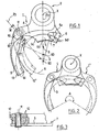
- the jaw 1 represented in FIG. attachment part 2 to a compressor cylinder of spring and a work part 3 connected to the part attachment 2 and intended to be engaged with a turn of the spring to compress.
- Work part 3 is in two pieces.
- a first piece 4, here in one piece with the attachment part 2 defines a section Track 5 circular, planar or helical. At one of its ends 5a, the narrowest, the track 5 is overhung by a leg 6 which forms a hook under which a spring coil can be slid.
- This tab 6 is from the inner edge 5b of track 5 which has a flange or bib 7 retaining the coil of the spring.
- This flap 7 extends to the figure all along the internal edge 5b of the track.
- this bib can occupy only the central part of this inner edge.
- the section of track is dug (reference 5d) or beveled so that the thickness of the wall of the room 4 which forms the track at this point is gradually diminished.
- This bevel allows to accommodate the end 5a from the end of the runway to the furthest point in the angle formed by a coil of spring leaving its end plate.
- the other end 5c of the runway section 5 is wider that the end 5a (in its dimension taken radially), which allows it to be able to accommodate such springs only 8, 9 of different winding diameter.
- the piece 4 bearing the runway section 5 has an articulation clevis 10 with an axis 11 on the outside of the runway, for a arm 12 which forms the second piece of the work part of the jaw and whose free end includes two edges 13 and 14 which define with the arm a cradle or gutter taking over the spire spring 8 or 9.
- the cradle 13, 14 of this arm can be replaced by an end possessing, as the end 5a of the section of runway, a leg overhanging a surface of taking charge of a spring coil.
- the end of the arm 12 can, also like the stretch of track, be of a diminished thickness gradually.
- the axis 11 is oriented so as to be substantially perpendicular on the surface of runway section 5 so that the end cradle of the arm 12 is substantially in the extension of the upper surface of the section runway 5.
- FIG. 3 is a sectional view along the line III-III of Figure 1 of the articulation of the arm 12 to the piece 4. We find in this figure the elements described previously with the same references.
- the end 5a of the track section and the end of the arm 12 is very largely circumferentially displaced by compared to a plan such as P3 that would go through the center spring and the center of the attachment part.
- the jaw according to the invention has all the advantages of the jaw deported being the subject of the French patent FR 2,674,167 in the name of the applicant.
- Figure 2 illustrates by a diagram on which represented in dotted line in addition to the jaw 1, a jaw 1 'in its working position when is hitched to the spring compression cylinder, for example to the rod of this cylinder while the jaw 1 is hitched to the body of it.
- the jaw 1 ' is, in the case of the figure, identical to the jaw 1 but returned so that both active surfaces of the jaws 1 and 1 'face each other.
- the spring 9 is caught between these two jaws so very enveloping, the angle A in the center of the spring 9, corresponding to the extent of the angular arches of the spring kissed by each jaw, being superior to 180 °.
- the spring thus compressed no longer tends to bend during compression.
- the invention offers increased ease of implementation of the compressor on the spring, thanks to the arm that at the time of assembly, one can first move away from the spring around its articulation then bring it closer after having correctly put in place - particularly towards the support base - one of the sections of track.
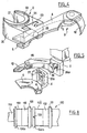
- an attachment part 2 of the jaw which is in the general form of a sleeve 20 whose central recess 21 is U-shaped open laterally on the opposite side to the work area 3 of the jaw.
- the sleeve 20 has at its end turned on the side of the back side of the working part, a countersink 22 whose inside diameter, greater to the width of the central recess 21, centered on the half-cylindrical part of the U-shaped recess 21 corresponds to the outer diameter of a body collar 101 100 of a compression cylinder (see Figure 8) while the width of the U-shaped opening 21 corresponds to the diameter of part 102 of this body 100 immediately adjacent at this collar 101.
- Exhibit 4 of the working part of the jaw according to the invention is not in one piece with the attachment part 2. Indeed the connection between part 4 and the part attachment 2 is effected by a T-slot 23 of this part of attachment that receives with play a head of link 24 complementary complementary form of the piece 4. Attachment part 2 and part 4 are furthermore connected to each other by an axis 25 which makes it possible to render indissociable these two elements while leaving a possibility to the room 4 to oscillate with respect to the part attachment 2 with a deflection that will function of the game left between the groove 23 and the head 24. The part of work 3 is then said to be pallet with respect to the Attachment part 2 of the jaw. This possibility swiveling or tilting of the working part allows to the jaw to take into account the variation of the angle spring propeller during compression.
- the attachment part 2 of the jaw who has a T-head 26 while piece 4 of the working part of the jaw part defining the track section 5, has an opening 27 capable to welcome with play the head 26.
- the lifting of this part 4 with respect to part 2 is performed as described in French patent FR 2,653,051, by the possible pivoting of the piece 4 on the foot 26a of the head 26 thanks to the lateral opening 27a in shape U of the opening 27.
- the arm 12 of the working part is articulated in a clevis 28 that is carried by the attachment part 2 of the jaw.
- the lifting is, in this variant embodiment, limited to piece that carries the section of track, which allows to improve the contact between this track and the coil of the spring.
- FIG. 6 there is shown a leg of force of a motor vehicle suspension which comprises known, a damper body provided with a plate 31, a damper rod 32, partially shown for the clarity of the drawing and which also carries a plate 33 and a spring 34 compressed between the two Plates 31 and 33.
- a damper body provided with a plate 31, a damper rod 32, partially shown for the clarity of the drawing and which also carries a plate 33 and a spring 34 compressed between the two Plates 31 and 33.
- two jaws 1 and 1 'of a compressor spring coupled to a cylinder 35.
- the area where the spring 34 leaves its support on the plate 31 is noted 36.
- the spring 34 leaves the plate 33 in the zone 37.
- the turn portions of spring 34 embraced by the jaws 1 and 1 'are respectively denoted 38 and 39 and their drawing is woven.
- Jaw 1 has been shown in its position where the end 5a is housed as close to the zone 36. It is found that the same end 5a of the jaw 1 ' is far from zone 37 which may be a slight inconvenience when compressing the spring but which has the advantage of leaving the compressor 35 a great angular latitude of setting up around the spring 34. This advantage is significant when it comes to under the vehicle that is to say in a space very cluttered around the plate 33 where often alone a small angular window is available to accept the cylinder.
- Figure 7 illustrates the use of a jaw 1 " at the level of plate 33 which is not identical to the jaw 1 but which is symmetrical with respect to a plane passing through the axis of his attachment part and by the axis of the springs to grasp (the plane P3 of Figure 1).
- This jaw 1 "allows to seize the spring closer of the zone 37 that the jaw 1 '(by the free end of his arm 12) but the wrapping of the spring by the compressor is less important.
- FIG 8 there is shown a cylinder body 100 having two collars 101 defining two possible positions of a jaw according to the invention along this body.
- Part 102 which overcomes each of the collars 101 has a threaded portion 103 which cooperates with a nut 104a, 104b for clamping the attachment portion of the cup against the corresponding flange 101.
- the realization of this cylinder body 100 is to achieve the threaded sections 103 before or after reporting the flange 101 farthest from the rod 110 by any suitable fastening means (welding, brazing, hooping ).
- the nut 104b is then reported on the thread 103 closest to this collar by having it previously split to make him pass the 102 zone no Threaded closest to the rod 110.
- the closure is carried out of its slot by a weld 105. We then put in place like the previous the second collar 101 and it is reported then the nut 104a.
Landscapes
- Engineering & Computer Science (AREA)
- Mechanical Engineering (AREA)
- Springs (AREA)
- Vehicle Body Suspensions (AREA)
- Compressors, Vaccum Pumps And Other Relevant Systems (AREA)
- Vibration Prevention Devices (AREA)
Description
- la figure 1 est une vue de la face active d'un premier mode de réalisation d'une mâchoire selon l'invention,
- la figure 2 est une vue semblable à celle de la figure 1 dans laquelle on a représenté en trait pointillé, une seconde mâchoire lorsqu'elle est attachée au vérin du compresseur de ressort,
- la figure 3 est une vue en coupe selon la ligne III-III de la figure 1,
- la figure 4 illustre une forme de réalisation de la partie d'attachement de la mâchoire de l'invention à un vérin de compresseur de ressort et une réalisation particulière de la liaison des parties d'attachement et de travail de la mâchoire,
- la figure 5 est une représentation schématique d'une autre forme de réalisation de la mâchoire selon l'invention dans laquelle le bras est articulé à la partie d'attachement au lieu d'être articulé à la pièce portant le tronçon de piste,
- les figures 6 et 7 sont des schémas illustrant un compresseur de ressort selon l'invention en prise avec un amortisseur,
- la figure 8 est une vue extérieure partielle d'un corps de vérin permettant l'attachement d'une mâchoire à deux niveaux.
Claims (8)
- Compresseur de ressorts comprenant un vérin avec un corps (100) et une tige (115) mobiles télescopiquement l'un par rapport à l'autre et deux mâchoires (1, 1') comprenant chacune une partie d'attachement (2) au vérin et une partie de travail (3) destinée à venir en prise avec une spire d'un ressort hélicoidal (8, 9), dans lequel la partie de travail (3) de chaque mâchoire comporte une première pièce (4) et une seconde pièce (12), articulées l'une par rapport à l'autre, la première pièce (4) étant reliée à la partie d'attachement (2), caractérisé en ce que la première pièce (4) porte un tronçon (5) de piste circulaire pour l'appui d'une portion d'une spire de ressort, pourvu le long de son bord intérieur d'un rebord (7) de retenue de la spire, et en ce que la seconde pièce est en forme de bras (12), articulé à la partie d'attachement (2) ou à la première pièce (4), au voisinage d'une extrémité (5c) du tronçon de piste (5) autour d'un axe (11) sensiblement perpendiculaire à la surface du tronçon de piste (5), qui forme par son extrémité libre une zone de prise en charge d'une spire du ressort.
- Compresseur de ressorts selon la revendication 1, caractérisé en ce qu'un plan bissecteur (P1, P2) de la portion de spire de ressort (8, 9) embrassée par la partie de travail (3) de la mâchoire est situé du côté du bras (12) par rapport à un plan (P3) passant par le centre du ressort et le centre (X) de la partie d'attachement de la mâchoire au vérin.
- Compresseur selon l'une quelconque des revendications précédentes, caractérisé en ce que le tronçon (5) de piste est de largeur croissante depuis son extrémité libre (5a) jusqu'à son extrémité (5c) voisine de l'articulation (11) du bras (12).
- Compresseur selon l'une des revendications précédentes, caractérisé en ce que la pièce (4) portant le tronçon de piste (5) comporte une patte (6) en surplomb de sa partie étroite (5a) à partir de son bord intérieur (5b).
- Compresseur selon la revendication 3 ou la revendication 4, caractérisé en ce que l'épaisseur de la paroi de la pièce (4) définissant le tronçon de piste (5) est progressivement amincie vers son extrémité libre dans la zone de sa partie étroite (5a).
- Compresseur selon l'une quelconque des revendications précédentes, caractérisé en ce que la liaison de la partie de travail (3) à la partie d'attachement (2) comporte un pivot (25, 26a) sensiblement parallèle à la surface de la piste (5) et passant sensiblement par le centre de la partie d'attachement (2).
- Compresseur selon l'une quelconque des revendications précédentes, caractérisé en ce que la partie d'attachement (2) de chaque mâchoire est en forme de manchon (20) relié latéralement à la partie de travail (3), dont l'évidement central (21) est en forme de U ouvert latéralement à l'opposé à la partie de travail (3) et dont au moins l'extrémité longitudinale située du côté de la face arrière de la mâchoire est munie d'un lamage (22) de diamètre supérieur à la largeur de l'évidement (21) en U.
- Compresseur selon la revendication 7, caractérisé en ce que le corps (100) du vérin comporte deux collerettes (101) espacées pour coopérer avec le lamage (22) de la mâchoire et un filetage (103) distant de chaque collerette (101) pour un écrou de serrage (104a, 104b) de la mâchoire contre cette collerette.
Applications Claiming Priority (3)
| Application Number | Priority Date | Filing Date | Title |
|---|---|---|---|
| FR0200295A FR2834660B1 (fr) | 2002-01-11 | 2002-01-11 | Compresseur de ressorts de suspension de vehicule automobile |
| FR0200295 | 2002-01-11 | ||
| PCT/FR2002/004524 WO2003057414A1 (fr) | 2002-01-11 | 2002-12-23 | Compresseur de ressorts de suspension de vehicule automobile |
Publications (2)
| Publication Number | Publication Date |
|---|---|
| EP1472049A1 EP1472049A1 (fr) | 2004-11-03 |
| EP1472049B1 true EP1472049B1 (fr) | 2005-09-28 |
Family
ID=8871241
Family Applications (1)
| Application Number | Title | Priority Date | Filing Date |
|---|---|---|---|
| EP02806034A Expired - Lifetime EP1472049B1 (fr) | 2002-01-11 | 2002-12-23 | Compresseur de ressorts de suspension de vehicule automobile |
Country Status (9)
| Country | Link |
|---|---|
| US (1) | US7114228B2 (fr) |
| EP (1) | EP1472049B1 (fr) |
| AT (1) | ATE305366T1 (fr) |
| AU (1) | AU2002365021A1 (fr) |
| CA (1) | CA2473022C (fr) |
| DE (1) | DE60206423T2 (fr) |
| ES (1) | ES2249643T3 (fr) |
| FR (1) | FR2834660B1 (fr) |
| WO (1) | WO2003057414A1 (fr) |
Families Citing this family (4)
| Publication number | Priority date | Publication date | Assignee | Title |
|---|---|---|---|---|
| US7103951B2 (en) * | 2005-02-08 | 2006-09-12 | Ismet Uzun | Strut spring compression apparatus |
| FR2886566B1 (fr) * | 2005-06-03 | 2009-01-16 | Patrick Lambert | Coupelle de surete pour compresseur de ressort |
| FR2897791B1 (fr) * | 2006-02-24 | 2008-05-09 | Patrick Lambert | Compresseur de ressorts |
| CN115805563B (zh) * | 2022-11-30 | 2024-07-02 | 深蓝汽车科技有限公司 | 弹簧压缩装置 |
Family Cites Families (10)
| Publication number | Priority date | Publication date | Assignee | Title |
|---|---|---|---|---|
| DE2813381C2 (de) * | 1978-03-28 | 1982-12-30 | Horst 7730 Villingen-Schwenningen Klann | Druckfedernspanner |
| DE3021084A1 (de) * | 1980-06-04 | 1981-12-24 | August Bilstein GmbH & Co KG, 5828 Ennepetal | Federspanngeraet |
| GB2117307B (en) * | 1982-03-18 | 1985-10-30 | Kenneth Donald Kloster | Helical spring compressor |
| DE3720018C2 (de) * | 1986-12-11 | 1988-09-29 | Horst Klann | Federnspanner |
| FR2653051A1 (fr) * | 1989-10-18 | 1991-04-19 | Mecanique Energetique | Dispositif de compression de ressorts. |
| DE9216147U1 (de) * | 1992-11-27 | 1993-03-25 | SSW Schmack Spezialwerkzeuge GmbH & Co. Entwicklungs KG, 6400 Fulda | Federspanner für die Montage von Schraubenfedern einer Fahrzeugfederung |
| JP3661021B2 (ja) * | 1995-11-10 | 2005-06-15 | カヤバ工業株式会社 | スプリングコンプレッサ |
| FR2749363A1 (fr) * | 1996-06-03 | 1997-12-05 | Mecanique Energetique | Compresseur de ressort a fluide sous pression |
| IT1308450B1 (it) * | 1999-04-23 | 2001-12-17 | Parodi Iva | Attrezzatura di smontaggio e di montaggio di gruppimolla-ammortizzatore per sospensioni di veicoli |
| US6336625B1 (en) * | 2000-08-28 | 2002-01-08 | Tsai-Tien Liao | Adjustable shock absorber mounting structure |
-
2002
- 2002-01-11 FR FR0200295A patent/FR2834660B1/fr not_active Expired - Fee Related
- 2002-12-23 AT AT02806034T patent/ATE305366T1/de not_active IP Right Cessation
- 2002-12-23 DE DE60206423T patent/DE60206423T2/de not_active Expired - Lifetime
- 2002-12-23 WO PCT/FR2002/004524 patent/WO2003057414A1/fr not_active Ceased
- 2002-12-23 US US10/500,386 patent/US7114228B2/en not_active Expired - Fee Related
- 2002-12-23 AU AU2002365021A patent/AU2002365021A1/en not_active Abandoned
- 2002-12-23 EP EP02806034A patent/EP1472049B1/fr not_active Expired - Lifetime
- 2002-12-23 CA CA002473022A patent/CA2473022C/fr not_active Expired - Fee Related
- 2002-12-23 ES ES02806034T patent/ES2249643T3/es not_active Expired - Lifetime
Also Published As
| Publication number | Publication date |
|---|---|
| FR2834660B1 (fr) | 2004-06-18 |
| ATE305366T1 (de) | 2005-10-15 |
| FR2834660A1 (fr) | 2003-07-18 |
| EP1472049A1 (fr) | 2004-11-03 |
| DE60206423D1 (de) | 2005-11-03 |
| DE60206423T2 (de) | 2006-07-06 |
| WO2003057414A1 (fr) | 2003-07-17 |
| AU2002365021A1 (en) | 2003-07-24 |
| US20050125977A1 (en) | 2005-06-16 |
| ES2249643T3 (es) | 2006-04-01 |
| CA2473022A1 (fr) | 2003-07-17 |
| CA2473022C (fr) | 2008-02-12 |
| US7114228B2 (en) | 2006-10-03 |
Similar Documents
| Publication | Publication Date | Title |
|---|---|---|
| EP2683897B1 (fr) | Dispositif d'assistance à l'ouverture d'un élément de recouvrement monté pivotant relativement à un bord d'un cadre | |
| CA2679079C (fr) | Dispositif de serrage a bras de manoeuvre escamotable et appareil comportant un tel dispositif | |
| EP1419837B1 (fr) | Mandrin porte-outil à système de verrouillage | |
| EP2389264B1 (fr) | Mandrin porte-outil pour l'équipement d'une machine tournante | |
| EP1423287B1 (fr) | Train arriere pour vehicule automobile du type a bras tires longitudinaux avec des barres de maintien ou de guidage transversal | |
| WO1998043010A1 (fr) | Collier de serrage pour le raccordement de deux tubes | |
| CA2473022C (fr) | Compresseur de ressorts de suspension de vehicule automobile | |
| WO2007054645A2 (fr) | Injecteur et cartouche de pliage d'implant ophtalmique | |
| CA2808507C (fr) | Rotor d'une machine de fenaison muni de bras en deux parties reliees par un dispositif de liaison perfectionne | |
| WO2001062533A1 (fr) | Toit escamotable dans le coffre arriere d'un vehicule, ce toit comportant une lunette arriere pivotante | |
| EP2662273B1 (fr) | Potence de cycle à chape de serrage | |
| WO2012143474A1 (fr) | Système de connexion pour la fixation d'un dispositif de portage | |
| EP4094960B1 (fr) | Train arriere pour vehicule automobile du type a deux bras tires longitudinaux a comportement elastique ameliore | |
| FR3070148A1 (fr) | Quadrilatere articule renforce pour un vehicule automobile | |
| FR2888166A1 (fr) | Bague d'arret destinee a etre montee sur une barre stabilisatrice d'une suspension de vehicule automobile | |
| WO2003091054A1 (fr) | Toit escamotable dans le coffre arriere d'un vehicule | |
| FR2939385A1 (fr) | Enemble de barres de toit pour vehicule automobile et vehicule automobile muni d'un tel ensemble. | |
| FR2910845A1 (fr) | Dispositif de commande du carrossage d'un vehicule. | |
| EP1722929B1 (fr) | Embout de prehension et de serrage destine a equiper un appareil de vissage | |
| CA3039993A1 (fr) | Machine de fenaison a rotors pourvus d'outils securises | |
| FR2911089A1 (fr) | Mecanisme de deplacement d'un toit mobile. | |
| EP3636400B1 (fr) | Prehenseur modulaire pour piece de carrosserie de vehicule | |
| FR2766767A1 (fr) | Dispositif permettant de deplacer un pare-brise de vehicule automobile entre une position debout d'utilisation et une position inactive rabattue | |
| EP1772297A1 (fr) | Traverse de train arrière de véhicule automobile | |
| FR2891957A1 (fr) | Boitier encastrable a vis de serrage guidee |
Legal Events
| Date | Code | Title | Description |
|---|---|---|---|
| PUAI | Public reference made under article 153(3) epc to a published international application that has entered the european phase |
Free format text: ORIGINAL CODE: 0009012 |
|
| 17P | Request for examination filed |
Effective date: 20040629 |
|
| AK | Designated contracting states |
Kind code of ref document: A1 Designated state(s): AT BE BG CH CY CZ DE DK EE ES FI FR GB GR IE IT LI LU MC NL PT SE SI SK TR |
|
| AX | Request for extension of the european patent |
Extension state: AL LT LV MK RO |
|
| GRAP | Despatch of communication of intention to grant a patent |
Free format text: ORIGINAL CODE: EPIDOSNIGR1 |
|
| GRAS | Grant fee paid |
Free format text: ORIGINAL CODE: EPIDOSNIGR3 |
|
| GRAA | (expected) grant |
Free format text: ORIGINAL CODE: 0009210 |
|
| AK | Designated contracting states |
Kind code of ref document: B1 Designated state(s): AT BE BG CH CY CZ DE DK EE ES FI FR GB GR IE IT LI LU MC NL PT SE SI SK TR |
|
| PG25 | Lapsed in a contracting state [announced via postgrant information from national office to epo] |
Ref country code: SK Free format text: LAPSE BECAUSE OF FAILURE TO SUBMIT A TRANSLATION OF THE DESCRIPTION OR TO PAY THE FEE WITHIN THE PRESCRIBED TIME-LIMIT Effective date: 20050928 Ref country code: NL Free format text: LAPSE BECAUSE OF FAILURE TO SUBMIT A TRANSLATION OF THE DESCRIPTION OR TO PAY THE FEE WITHIN THE PRESCRIBED TIME-LIMIT Effective date: 20050928 Ref country code: SI Free format text: LAPSE BECAUSE OF FAILURE TO SUBMIT A TRANSLATION OF THE DESCRIPTION OR TO PAY THE FEE WITHIN THE PRESCRIBED TIME-LIMIT Effective date: 20050928 Ref country code: FI Free format text: LAPSE BECAUSE OF FAILURE TO SUBMIT A TRANSLATION OF THE DESCRIPTION OR TO PAY THE FEE WITHIN THE PRESCRIBED TIME-LIMIT Effective date: 20050928 Ref country code: IE Free format text: LAPSE BECAUSE OF FAILURE TO SUBMIT A TRANSLATION OF THE DESCRIPTION OR TO PAY THE FEE WITHIN THE PRESCRIBED TIME-LIMIT Effective date: 20050928 Ref country code: EE Free format text: LAPSE BECAUSE OF FAILURE TO SUBMIT A TRANSLATION OF THE DESCRIPTION OR TO PAY THE FEE WITHIN THE PRESCRIBED TIME-LIMIT Effective date: 20050928 Ref country code: AT Free format text: LAPSE BECAUSE OF FAILURE TO SUBMIT A TRANSLATION OF THE DESCRIPTION OR TO PAY THE FEE WITHIN THE PRESCRIBED TIME-LIMIT Effective date: 20050928 |
|
| REG | Reference to a national code |
Ref country code: GB Ref legal event code: FG4D Free format text: NOT ENGLISH |
|
| REG | Reference to a national code |
Ref country code: CH Ref legal event code: EP |
|
| REG | Reference to a national code |
Ref country code: IE Ref legal event code: FG4D Free format text: LANGUAGE OF EP DOCUMENT: FRENCH |
|
| REF | Corresponds to: |
Ref document number: 60206423 Country of ref document: DE Date of ref document: 20051103 Kind code of ref document: P |
|
| REG | Reference to a national code |
Ref country code: CH Ref legal event code: NV Representative=s name: BOVARD AG PATENTANWAELTE |
|
| GBT | Gb: translation of ep patent filed (gb section 77(6)(a)/1977) |
Effective date: 20051111 |
|
| PG25 | Lapsed in a contracting state [announced via postgrant information from national office to epo] |
Ref country code: CY Free format text: LAPSE BECAUSE OF FAILURE TO SUBMIT A TRANSLATION OF THE DESCRIPTION OR TO PAY THE FEE WITHIN THE PRESCRIBED TIME-LIMIT Effective date: 20051223 |
|
| PG25 | Lapsed in a contracting state [announced via postgrant information from national office to epo] |
Ref country code: GR Free format text: LAPSE BECAUSE OF FAILURE TO SUBMIT A TRANSLATION OF THE DESCRIPTION OR TO PAY THE FEE WITHIN THE PRESCRIBED TIME-LIMIT Effective date: 20051228 Ref country code: BG Free format text: LAPSE BECAUSE OF FAILURE TO SUBMIT A TRANSLATION OF THE DESCRIPTION OR TO PAY THE FEE WITHIN THE PRESCRIBED TIME-LIMIT Effective date: 20051228 Ref country code: DK Free format text: LAPSE BECAUSE OF FAILURE TO SUBMIT A TRANSLATION OF THE DESCRIPTION OR TO PAY THE FEE WITHIN THE PRESCRIBED TIME-LIMIT Effective date: 20051228 Ref country code: SE Free format text: LAPSE BECAUSE OF FAILURE TO SUBMIT A TRANSLATION OF THE DESCRIPTION OR TO PAY THE FEE WITHIN THE PRESCRIBED TIME-LIMIT Effective date: 20051228 |
|
| PG25 | Lapsed in a contracting state [announced via postgrant information from national office to epo] |
Ref country code: MC Free format text: LAPSE BECAUSE OF NON-PAYMENT OF DUE FEES Effective date: 20051231 |
|
| PG25 | Lapsed in a contracting state [announced via postgrant information from national office to epo] |
Ref country code: PT Free format text: LAPSE BECAUSE OF FAILURE TO SUBMIT A TRANSLATION OF THE DESCRIPTION OR TO PAY THE FEE WITHIN THE PRESCRIBED TIME-LIMIT Effective date: 20060228 |
|
| NLV1 | Nl: lapsed or annulled due to failure to fulfill the requirements of art. 29p and 29m of the patents act | ||
| REG | Reference to a national code |
Ref country code: ES Ref legal event code: FG2A Ref document number: 2249643 Country of ref document: ES Kind code of ref document: T3 |
|
| REG | Reference to a national code |
Ref country code: IE Ref legal event code: FD4D |
|
| PLBE | No opposition filed within time limit |
Free format text: ORIGINAL CODE: 0009261 |
|
| STAA | Information on the status of an ep patent application or granted ep patent |
Free format text: STATUS: NO OPPOSITION FILED WITHIN TIME LIMIT |
|
| 26N | No opposition filed |
Effective date: 20060629 |
|
| REG | Reference to a national code |
Ref country code: CH Ref legal event code: PFA Owner name: MECANIQUE ENERGETIQUE Free format text: MECANIQUE ENERGETIQUE#16 RUE DE CHEVRY#F-77620 EGREVILLE (FR) -TRANSFER TO- MECANIQUE ENERGETIQUE#16 RUE DE CHEVRY#F-77620 EGREVILLE (FR) |
|
| PGFP | Annual fee paid to national office [announced via postgrant information from national office to epo] |
Ref country code: TR Payment date: 20131125 Year of fee payment: 12 |
|
| PGFP | Annual fee paid to national office [announced via postgrant information from national office to epo] |
Ref country code: CH Payment date: 20141219 Year of fee payment: 13 Ref country code: LU Payment date: 20141230 Year of fee payment: 13 Ref country code: CZ Payment date: 20141218 Year of fee payment: 13 |
|
| REG | Reference to a national code |
Ref country code: DE Ref legal event code: R082 Ref document number: 60206423 Country of ref document: DE Representative=s name: SCHAUMBURG UND PARTNER PATENTANWAELTE MBB, DE Ref country code: DE Ref legal event code: R082 Ref document number: 60206423 Country of ref document: DE Representative=s name: SCHAUMBURG & PARTNER PATENTANWAELTE GBR, DE Ref country code: DE Ref legal event code: R082 Ref document number: 60206423 Country of ref document: DE Representative=s name: SCHAUMBURG & PARTNER PATENTANWAELTE MBB, DE |
|
| PGFP | Annual fee paid to national office [announced via postgrant information from national office to epo] |
Ref country code: BE Payment date: 20141219 Year of fee payment: 13 |
|
| REG | Reference to a national code |
Ref country code: FR Ref legal event code: PLFP Year of fee payment: 14 |
|
| PGFP | Annual fee paid to national office [announced via postgrant information from national office to epo] |
Ref country code: GB Payment date: 20151221 Year of fee payment: 14 Ref country code: DE Payment date: 20151210 Year of fee payment: 14 |
|
| PGFP | Annual fee paid to national office [announced via postgrant information from national office to epo] |
Ref country code: ES Payment date: 20151214 Year of fee payment: 14 Ref country code: FR Payment date: 20151130 Year of fee payment: 14 |
|
| PGFP | Annual fee paid to national office [announced via postgrant information from national office to epo] |
Ref country code: IT Payment date: 20151228 Year of fee payment: 14 |
|
| PG25 | Lapsed in a contracting state [announced via postgrant information from national office to epo] |
Ref country code: BE Free format text: LAPSE BECAUSE OF NON-PAYMENT OF DUE FEES Effective date: 20151231 |
|
| PG25 | Lapsed in a contracting state [announced via postgrant information from national office to epo] |
Ref country code: LU Free format text: LAPSE BECAUSE OF NON-PAYMENT OF DUE FEES Effective date: 20151223 Ref country code: CZ Free format text: LAPSE BECAUSE OF NON-PAYMENT OF DUE FEES Effective date: 20151223 |
|
| REG | Reference to a national code |
Ref country code: CH Ref legal event code: PL |
|
| PG25 | Lapsed in a contracting state [announced via postgrant information from national office to epo] |
Ref country code: LI Free format text: LAPSE BECAUSE OF NON-PAYMENT OF DUE FEES Effective date: 20151231 Ref country code: CH Free format text: LAPSE BECAUSE OF NON-PAYMENT OF DUE FEES Effective date: 20151231 |
|
| REG | Reference to a national code |
Ref country code: DE Ref legal event code: R119 Ref document number: 60206423 Country of ref document: DE |
|
| GBPC | Gb: european patent ceased through non-payment of renewal fee |
Effective date: 20161223 |
|
| PG25 | Lapsed in a contracting state [announced via postgrant information from national office to epo] |
Ref country code: TR Free format text: LAPSE BECAUSE OF NON-PAYMENT OF DUE FEES Effective date: 20151223 |
|
| REG | Reference to a national code |
Ref country code: FR Ref legal event code: ST Effective date: 20170831 |
|
| PG25 | Lapsed in a contracting state [announced via postgrant information from national office to epo] |
Ref country code: FR Free format text: LAPSE BECAUSE OF NON-PAYMENT OF DUE FEES Effective date: 20170102 Ref country code: IT Free format text: LAPSE BECAUSE OF NON-PAYMENT OF DUE FEES Effective date: 20161223 |
|
| PG25 | Lapsed in a contracting state [announced via postgrant information from national office to epo] |
Ref country code: GB Free format text: LAPSE BECAUSE OF NON-PAYMENT OF DUE FEES Effective date: 20161223 Ref country code: DE Free format text: LAPSE BECAUSE OF NON-PAYMENT OF DUE FEES Effective date: 20170701 |
|
| PG25 | Lapsed in a contracting state [announced via postgrant information from national office to epo] |
Ref country code: ES Free format text: LAPSE BECAUSE OF NON-PAYMENT OF DUE FEES Effective date: 20161224 |
|
| REG | Reference to a national code |
Ref country code: ES Ref legal event code: FD2A Effective date: 20181116 |