EP1471864B1 - Passive motion apparatus providing a controlled range of motion - Google Patents
Passive motion apparatus providing a controlled range of motion Download PDFInfo
- Publication number
- EP1471864B1 EP1471864B1 EP03702024.5A EP03702024A EP1471864B1 EP 1471864 B1 EP1471864 B1 EP 1471864B1 EP 03702024 A EP03702024 A EP 03702024A EP 1471864 B1 EP1471864 B1 EP 1471864B1
- Authority
- EP
- European Patent Office
- Prior art keywords
- support member
- support
- user
- legs
- movement
- Prior art date
- Legal status (The legal status is an assumption and is not a legal conclusion. Google has not performed a legal analysis and makes no representation as to the accuracy of the status listed.)
- Expired - Lifetime
Links
- 230000033001 locomotion Effects 0.000 title claims description 74
- 210000002414 leg Anatomy 0.000 description 63
- 230000007246 mechanism Effects 0.000 description 13
- 244000309466 calf Species 0.000 description 9
- 210000001217 buttock Anatomy 0.000 description 6
- 208000008035 Back Pain Diseases 0.000 description 5
- 238000010276 construction Methods 0.000 description 5
- 238000010586 diagram Methods 0.000 description 4
- 238000011282 treatment Methods 0.000 description 4
- 208000002193 Pain Diseases 0.000 description 3
- 230000009286 beneficial effect Effects 0.000 description 3
- 208000037265 diseases, disorders, signs and symptoms Diseases 0.000 description 3
- 208000035475 disorder Diseases 0.000 description 3
- 208000027418 Wounds and injury Diseases 0.000 description 2
- 210000004712 air sac Anatomy 0.000 description 2
- 230000006378 damage Effects 0.000 description 2
- 230000036541 health Effects 0.000 description 2
- 208000014674 injury Diseases 0.000 description 2
- 230000002452 interceptive effect Effects 0.000 description 2
- 210000004705 lumbosacral region Anatomy 0.000 description 2
- 210000003205 muscle Anatomy 0.000 description 2
- 230000004044 response Effects 0.000 description 2
- 230000001225 therapeutic effect Effects 0.000 description 2
- 208000008930 Low Back Pain Diseases 0.000 description 1
- 208000029549 Muscle injury Diseases 0.000 description 1
- 206010028836 Neck pain Diseases 0.000 description 1
- 206010061363 Skeletal injury Diseases 0.000 description 1
- 210000003489 abdominal muscle Anatomy 0.000 description 1
- 210000003679 cervix uteri Anatomy 0.000 description 1
- 230000008859 change Effects 0.000 description 1
- 238000001816 cooling Methods 0.000 description 1
- 239000006260 foam Substances 0.000 description 1
- 230000004886 head movement Effects 0.000 description 1
- 238000010438 heat treatment Methods 0.000 description 1
- 238000005461 lubrication Methods 0.000 description 1
- 238000012423 maintenance Methods 0.000 description 1
- 238000004519 manufacturing process Methods 0.000 description 1
- 239000000463 material Substances 0.000 description 1
- 230000004048 modification Effects 0.000 description 1
- 238000012986 modification Methods 0.000 description 1
- 230000003387 muscular Effects 0.000 description 1
- 238000011084 recovery Methods 0.000 description 1
- 230000000452 restraining effect Effects 0.000 description 1
- 230000003068 static effect Effects 0.000 description 1
- 238000011269 treatment regimen Methods 0.000 description 1
- 238000012559 user support system Methods 0.000 description 1
Images


Classifications
-
- A—HUMAN NECESSITIES
- A61—MEDICAL OR VETERINARY SCIENCE; HYGIENE
- A61H—PHYSICAL THERAPY APPARATUS, e.g. DEVICES FOR LOCATING OR STIMULATING REFLEX POINTS IN THE BODY; ARTIFICIAL RESPIRATION; MASSAGE; BATHING DEVICES FOR SPECIAL THERAPEUTIC OR HYGIENIC PURPOSES OR SPECIFIC PARTS OF THE BODY
- A61H1/00—Apparatus for passive exercising; Vibrating apparatus ; Chiropractic devices, e.g. body impacting devices, external devices for briefly extending or aligning unbroken bones
- A61H1/02—Stretching or bending or torsioning apparatus for exercising
- A61H1/0292—Stretching or bending or torsioning apparatus for exercising for the spinal column
-
- A—HUMAN NECESSITIES
- A61—MEDICAL OR VETERINARY SCIENCE; HYGIENE
- A61G—TRANSPORT, PERSONAL CONVEYANCES, OR ACCOMMODATION SPECIALLY ADAPTED FOR PATIENTS OR DISABLED PERSONS; OPERATING TABLES OR CHAIRS; CHAIRS FOR DENTISTRY; FUNERAL DEVICES
- A61G13/00—Operating tables; Auxiliary appliances therefor
- A61G13/009—Physiotherapeutic tables, beds or platforms; Chiropractic or osteopathic tables
-
- A—HUMAN NECESSITIES
- A61—MEDICAL OR VETERINARY SCIENCE; HYGIENE
- A61H—PHYSICAL THERAPY APPARATUS, e.g. DEVICES FOR LOCATING OR STIMULATING REFLEX POINTS IN THE BODY; ARTIFICIAL RESPIRATION; MASSAGE; BATHING DEVICES FOR SPECIAL THERAPEUTIC OR HYGIENIC PURPOSES OR SPECIFIC PARTS OF THE BODY
- A61H1/00—Apparatus for passive exercising; Vibrating apparatus ; Chiropractic devices, e.g. body impacting devices, external devices for briefly extending or aligning unbroken bones
- A61H1/001—Apparatus for applying movements to the whole body
- A61H1/003—Rocking or oscillating around a horizontal axis transversal to the body
-
- A—HUMAN NECESSITIES
- A61—MEDICAL OR VETERINARY SCIENCE; HYGIENE
- A61H—PHYSICAL THERAPY APPARATUS, e.g. DEVICES FOR LOCATING OR STIMULATING REFLEX POINTS IN THE BODY; ARTIFICIAL RESPIRATION; MASSAGE; BATHING DEVICES FOR SPECIAL THERAPEUTIC OR HYGIENIC PURPOSES OR SPECIFIC PARTS OF THE BODY
- A61H1/00—Apparatus for passive exercising; Vibrating apparatus ; Chiropractic devices, e.g. body impacting devices, external devices for briefly extending or aligning unbroken bones
- A61H1/02—Stretching or bending or torsioning apparatus for exercising
- A61H1/0218—Drawing-out devices
- A61H1/0222—Traction tables
-
- A—HUMAN NECESSITIES
- A61—MEDICAL OR VETERINARY SCIENCE; HYGIENE
- A61H—PHYSICAL THERAPY APPARATUS, e.g. DEVICES FOR LOCATING OR STIMULATING REFLEX POINTS IN THE BODY; ARTIFICIAL RESPIRATION; MASSAGE; BATHING DEVICES FOR SPECIAL THERAPEUTIC OR HYGIENIC PURPOSES OR SPECIFIC PARTS OF THE BODY
- A61H1/00—Apparatus for passive exercising; Vibrating apparatus ; Chiropractic devices, e.g. body impacting devices, external devices for briefly extending or aligning unbroken bones
- A61H1/02—Stretching or bending or torsioning apparatus for exercising
- A61H1/0237—Stretching or bending or torsioning apparatus for exercising for the lower limbs
-
- A—HUMAN NECESSITIES
- A61—MEDICAL OR VETERINARY SCIENCE; HYGIENE
- A61H—PHYSICAL THERAPY APPARATUS, e.g. DEVICES FOR LOCATING OR STIMULATING REFLEX POINTS IN THE BODY; ARTIFICIAL RESPIRATION; MASSAGE; BATHING DEVICES FOR SPECIAL THERAPEUTIC OR HYGIENIC PURPOSES OR SPECIFIC PARTS OF THE BODY
- A61H1/00—Apparatus for passive exercising; Vibrating apparatus ; Chiropractic devices, e.g. body impacting devices, external devices for briefly extending or aligning unbroken bones
- A61H1/02—Stretching or bending or torsioning apparatus for exercising
- A61H1/0292—Stretching or bending or torsioning apparatus for exercising for the spinal column
- A61H1/0296—Neck
-
- A—HUMAN NECESSITIES
- A61—MEDICAL OR VETERINARY SCIENCE; HYGIENE
- A61H—PHYSICAL THERAPY APPARATUS, e.g. DEVICES FOR LOCATING OR STIMULATING REFLEX POINTS IN THE BODY; ARTIFICIAL RESPIRATION; MASSAGE; BATHING DEVICES FOR SPECIAL THERAPEUTIC OR HYGIENIC PURPOSES OR SPECIFIC PARTS OF THE BODY
- A61H2201/00—Characteristics of apparatus not provided for in the preceding codes
- A61H2201/16—Physical interface with patient
- A61H2201/1602—Physical interface with patient kind of interface, e.g. head rest, knee support or lumbar support
- A61H2201/1604—Head
- A61H2201/1607—Holding means therefor
-
- A—HUMAN NECESSITIES
- A61—MEDICAL OR VETERINARY SCIENCE; HYGIENE
- A61H—PHYSICAL THERAPY APPARATUS, e.g. DEVICES FOR LOCATING OR STIMULATING REFLEX POINTS IN THE BODY; ARTIFICIAL RESPIRATION; MASSAGE; BATHING DEVICES FOR SPECIAL THERAPEUTIC OR HYGIENIC PURPOSES OR SPECIFIC PARTS OF THE BODY
- A61H2201/00—Characteristics of apparatus not provided for in the preceding codes
- A61H2201/16—Physical interface with patient
- A61H2201/1602—Physical interface with patient kind of interface, e.g. head rest, knee support or lumbar support
- A61H2201/164—Feet or leg, e.g. pedal
- A61H2201/1642—Holding means therefor
-
- A—HUMAN NECESSITIES
- A61—MEDICAL OR VETERINARY SCIENCE; HYGIENE
- A61H—PHYSICAL THERAPY APPARATUS, e.g. DEVICES FOR LOCATING OR STIMULATING REFLEX POINTS IN THE BODY; ARTIFICIAL RESPIRATION; MASSAGE; BATHING DEVICES FOR SPECIAL THERAPEUTIC OR HYGIENIC PURPOSES OR SPECIFIC PARTS OF THE BODY
- A61H2203/00—Additional characteristics concerning the patient
- A61H2203/04—Position of the patient
- A61H2203/0443—Position of the patient substantially horizontal
- A61H2203/045—Position of the patient substantially horizontal with legs in a kneeled 90°/90°-position
-
- A—HUMAN NECESSITIES
- A61—MEDICAL OR VETERINARY SCIENCE; HYGIENE
- A61H—PHYSICAL THERAPY APPARATUS, e.g. DEVICES FOR LOCATING OR STIMULATING REFLEX POINTS IN THE BODY; ARTIFICIAL RESPIRATION; MASSAGE; BATHING DEVICES FOR SPECIAL THERAPEUTIC OR HYGIENIC PURPOSES OR SPECIFIC PARTS OF THE BODY
- A61H2203/00—Additional characteristics concerning the patient
- A61H2203/04—Position of the patient
- A61H2203/0443—Position of the patient substantially horizontal
- A61H2203/0475—Position of the patient substantially horizontal on the side
Landscapes
- Health & Medical Sciences (AREA)
- Life Sciences & Earth Sciences (AREA)
- Animal Behavior & Ethology (AREA)
- Public Health (AREA)
- Physical Education & Sports Medicine (AREA)
- Rehabilitation Therapy (AREA)
- Veterinary Medicine (AREA)
- General Health & Medical Sciences (AREA)
- Pain & Pain Management (AREA)
- Epidemiology (AREA)
- Engineering & Computer Science (AREA)
- Biomedical Technology (AREA)
- Orthopedic Medicine & Surgery (AREA)
- Biophysics (AREA)
- Neurology (AREA)
- Rehabilitation Tools (AREA)
- Orthopedics, Nursing, And Contraception (AREA)
- Thermotherapy And Cooling Therapy Devices (AREA)
Description
- The present invention relates to exercise and therapeutic devices and, more particularly, to passive motion devices, i.e., devices which put a passive user through prescribed movements without effort on the part of the user.
- It is estimated that in the United States alone, as of the mid-1990s, there were 25,000,000 people a day who suffered from some kind of back pain and that as many as nine out of ten Americans will suffer back pain at some time in their lives. The resultant total economic burden on industry in the United States is estimated at $40 to $50 billion annually.
- One approach to relieving back pain and cervical pain is through exercise or therapeutic movement, and a substantial number of exercise devices and machines have been developed for exercising the back. However, many of these devices are unsuitable for persons suffering from serious back pain because use thereof tends to increase the pain and/or because there is danger of injury (or further injury) to the back, e.g., to the spine or to the supporting muscles.
- One approach to exercising of the back and other parts of the body involves the use of passive exercise machines, i.e., machines that exercise muscles of the user (e.g., the back and abdominal muscles) without any active effort on the part of the user. A number of these devices and machines include separate support sections for supporting different parts of the body (e.g., the head and upper torso are supported on one section and the lower torso and legs on a second section) and are motorized so that, e.g., while the user lies flat on his or her back, the lower torso and legs are moved as a unit with respect to the upper torso and head which remain stationary, so as to provide automatic side flexion. Such machines include conventional "toning tables" as well as specially designed devices such as the "electric flexion distraction table" made by Health Care Manufacturing of Springfield, Missouri and the SPINALATOR® machine made by the Chattanooga Group, Inc. of Hixon, Tennessee.
- Patented devices of interest include those disclosed in
U.S. Patent Nos. 5,500,002 (Riddle et al. );5,320,641 (Riddle et al. );5,123,916 (Riddle et al. );4,827,913 (Parker );4,144,880 (Daniels );6,086,550 (Richardson );4,953,541 (Parker, Jr. );5,044,359 (Reinert );5,171,260 (Mcllwain );5,035,234 (Forsythe ); and3,674,017 (Stefani, Jr. ). Briefly considering some of these patents, the Riddle et al. patents all disclose passive exercise devices designed for the lower back region. The devices feature two sets of support means, one for the upper body and one for the lower body. The device is designed such that either one, or both of the two support means may be pivoted up or down. The Parker patent discloses a passive exercise device which includes interchangeable components adapted to be attached to the table apparatus. The device is deigned to provide leg exercises in a variety of different positions. The Daniels patent discloses a passive traction/motion device. A cervical traction device is also provided. The Richardson patent discloses a passive exercise device in which the patient may be reclined in the so-called "90/90" position described below. The legs of the patient are placed in a leg rest which may be removed from a table portion. The device provides a variable speed rocking motion (in an elliptical path) to the legs and torso of the user. Another device of interest is disclosed inU.S. Patent 5,300,090 which features two user support surfaces connected through a vertical pivot axis passing through the region where the user's hips will generally be located. - In accordance with the invention, a continuous passive motion apparatus or machine is provided which affords a number of important advantages. The invention is based, in part, on the appreciation that continuous passive motion, particularly when combined with traction, can be beneficial in treating various muscular and skeletal injuries or disorders, and on the belief held by many health care professionals that the slow and passive movement of an injured joint or like disorder can reduce pain and/or speed the recovery of many patients with such disorders.
- According to a first aspect of the invention, a passive motion apparatus is provided, the apparatus comprising: a main support assembly for supporting at least part of the body of a user of the apparatus and including a first support member including a substantially horizontal support surface defining a plane and a second support member including a substantially horizontal support surface disposed in said plane, said second support member being pivotably connected to said first support member and being movable relative thereto such that movement of the second support member with respect to the first support member provides passive movement of a part of the body of a user supported by said second member relative to a part of the body supported by said first support member; a separable leg support assembly adapted to be connected, in use, to said main support assembly at either end of said main support assembly so as to support at least part of the legs of the user; and motorized drive means for providing said movement of said second support member relative to said first support member.
- The leg support assembly includes a support platform and a support strut for, when said leg support assembly is positioned at one end of said main support assembly so as to be disposed adjacent to said second support member, supporting said platform in a plane elevated with respect to the first-mentioned plane such that lower portions of the legs of the user are elevated with respect to the remainder of the body of the user and such that upper portions of the legs of the user extend at substantially right angles with respect to the lower portions of the legs and the trunk of the body of the user. The leg support assembly further includes means for pivotably mounting said support platform with respect to said support strut so as to enable angular adjustment of the support platform about the support strut.
- In another embodiment, the leg support assembly comprises a leg support member defining an upper support surface and means for detachably affixing the leg support member to said main support assembly such that said upper surface of said leg support member is disposed substantially in said plane. Advantageously, the leg support member is adapted to be selectively connected to said main support assembly at either one of the two opposite sides of the main support assembly.
- Preferably, the motorized drive means comprises an electric drive motor and control means for selectively controlling the operation of said motor. Advantageously, the control means comprises programmable means for controlling the motor so as to control the amount of pivoting movement of said second support member relative to said first support member.
- The control means preferably includes a stop switch adapted to be operated by a user of the apparatus to terminate the relative movement of said second support member. In an advantageous implementation, the motor comprises a gear head motor and said drive means further comprises a worm screw mounted on said first support member and being driven in rotation by said motor, a traveling nut mounted on said worm screw for travel therealong in response to rotation of said worm screw by said motor, and a link pivotably connected to said traveling nut and to said second support member so as to cause said pivoting movement of said second support member in response to travel of said traveling nut along said worm screw.
- Preferably, the passive motion exercise apparatus further comprises at least one temperature control pack removably disposed on one of said first and second support members. Advantageously, the temperature control packs comprise one of (i) at least one cold pack and (ii) at least one hot pack.
- In a preferred implementation, the passive motion exercise apparatus further comprises a safety belt affixed to said second support member. Advantageously, a pair of laterally spaced hand grips are provided which are affixed to one end of said first support member but can be affixed to either support member.
- In an advantageous embodiment, the second support member includes inflatable means, including first and second alternately inflatable sections, for providing rotational movement of a part of the body received thereon. The first and second sections preferably comprise first and second inflatable bladders disposed in side by side relation and said inflatable means further comprises an air pump and means for connecting the pump to said bladders so that the pump provides alternate inflation and deflation of said first and second bladders.
- In a beneficial implementation, one of said first and second support members includes cervical rotation means for rotating the neck and head of a user. Preferably, the cervical rotation means includes a curved support member in which the head of a user is received, curved race, a plurality of bearings, disposed between said curved support and said curved race, for permitting movement of said curved support member relative to said race, and drive means for producing movement of said curved support member.
- Advantageously, the passive motion apparatus further comprises traction means for supporting at least one part of the body of a user in traction.
- In accordance with a further aspect of the invention, there is provided a passive motion exercise apparatus for exercising the back of a user by providing passive motion of the lower trunk and legs of a user relative to the remainder of the body of the user, the apparatus comprising: a first elevated support member for, in use, supporting, back down, the upper trunk and head of the user; a second elevated support member, movable with respect to said first support member, and disposed at a common level with, and adjacent to, said first support member, for in use, supporting, buttocks down, the lower trunk of the user; means for providing pivotable movement of said second support member in a common plane about a vertical axis disposed centrally of said first support member; and a third elevated support member, disposed in a plane elevated with respect to said common plane and disposed adjacent to said second support member, for supporting the lower portions of the legs of the user so that, in use, the upper leg portions of the user extend at substantially 90° to both the lower trunk of the user and the lower portions of the legs of the user.
- Preferably, the third leg support member includes a support strut, a support platform and means for pivotably mounting said support platform with respect to said support strut so as to enable angular adjustment of the support platform about the support strut so as to change the position of the lower legs of the user.
- Advantageously, at least one temperature control pack is removably disposed on one of said first and second support members, said at least one temperature control pack comprising one of (i) at least one cold pack and (ii) at least one hot pack.
- Preferably, a safety belt is affixed to said second support member.
- In accordance with an illustrative example, there is provided passive motion exercise apparatus comprising: a main support assembly for supporting at least part of the body of a user of the apparatus and including a first support member including a substantially horizontal support surface defining a first plane and a second support member including a substantially horizontal support surface disposed in said plane, said second support member being pivotably connected to said first support member and being movable relative thereto such that movement of the second support member with respect to the first support member provides passive movement of a part of the body of a user supported by said second member relative to a part of the body supported by said first support member; a first, separable leg support assembly adapted to be connected, in use, to said main support assembly at either end of said main support assembly so as to support at least part of the legs of the user in a second plane elevated with respect to said first plane; a further, separable leg support assembly, for use when said first leg support assembly is not being used, said further leg support assembly comprising a leg support member defining an upper support surface and adapted to be connected, in use, to said main support assembly such that said upper surface of said leg support member is disposed substantially in said plane; and motorized drive means for providing said movement of said second support member relative to said first support member.
- Preferably, said first leg support assembly includes a support platform and a support strut for, when said leg support assembly is positioned at one end of said main support assembly so as to be disposed adjacent to said second support member, supporting said platform in said second elevated plane such that lower portions of the legs of the user are elevated with respect to the remainder of the body of the user and such that upper portions of the legs of the user extend at substantially right angles with respect to the lower portions of the legs and the trunk of the body of the user. Advantageously, said leg support assembly further includes self-adjusting means for pivotably mounting said support platform with respect to said support strut so as to enable angular adjustment of the support platform about the support strut.
- In accordance with a still further aspect of the invention, there is provided a passive motion apparatus for providing passive motion of the lower trunk and legs of a user relative to the remainder of the body of the user, the apparatus comprising: a body support unit comprising: a first support member for, in use, engaging the upper trunk and head of a user; a second support member, movable with respect to said first support member and disposed adjacent to said first support member, for, in use, engaging the buttocks of the user; a third support member, disposed adjacent to said second support member in a different plane therefrom, for engaging the lower portions of the legs of the user so that, in use, the upper leg portions of the user extend at substantially 90° to both the lower trunk of the user and the lower portions of the legs of the user; and means for providing lateral pivotable movement of said second and third support members relative to said first support member; and a stationary base for pivotably supporting said body support unit so as to enable pivoting of said body support unit between a first, substantially vertical position wherein a user is supported in seated posture on said body support unit and a second, substantially horizontal position wherein a user is supported in a reclining posture on said body support unit. "
- As in the other embodiments, the third support member preferably comprises a support strut, a support platform, and means for pivotably mounting said support platform with respect to said support strut so as to enable angular adjustment of the support platform about the support strut.
- Preferably, the second support member extends outwardly at a non-zero angle with respect to said first support member so as to act as a seat in said first position of said body support unit.
- In an advantageous implementation of this aspect of the invention, the body support unit includes a fourth support member interposed between the first and second support members and affixed to the second support member for movement therewith so as to undergo lateral pivotable movement with the second support member.
- Further features and advantages of the present invention will be set forth in, or apparent from, the detailed description of preferred embodiments thereof which follows.
-
-
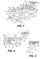
Figure 1 is a perspective view of a passive range of motion exercise and/or treatment apparatus in accordance with a preferred embodiment of the invention; -
Figure 2 is a side elevational view of the device ofFigure 1 showing a different component configuration; -
Figure 3 is a side elevational view of the lower leg (calf) support assembly ofFigures 1 and 2 ; -
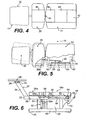
Figure 4 is a top plan view of the apparatus ofFigure 1 , showing certain optional features thereof; -
Figure 5 is a further top plan view of the apparatus ofFigure 1 , partially broken away to show the operating mechanism therefor and with the optional features ofFigure 4 omitted; -
Figure 6 is a side elevational view of the apparatus ofFigure 5 ; -
Figure 7 is a schematic circuit diagram of a preferred embodiment of a control circuit for the apparatus ofFigure 1 ; -
Figure 8 is a schematic circuit diagram of a preferred embodiment of one unit (the bridge rectifier unit) of the circuit ofFigure 7 ; -
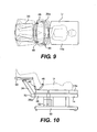
Figures 9 and 10 are a top plan view and a side elevational view, respectively, of the apparatus ofFigure 1 , showing one mode of operation thereof; -
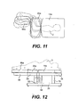
Figures 11 and 12 are a top plan view and a side elevational view, respectively, of a modified form of the apparatus ofFigure 1 , showing a further mode of operation; -
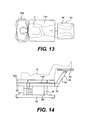
Figures 13 and 14 are a top plan view and a side elevational view, respectively, of a different configuration of the apparatus ofFigure 1 , showing a further mode of operation; -
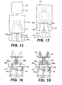
Figures 15 and 16 are a top plan view and an end elevational view, respectively, of a modified form of the apparatus ofFigure 1 , illustrating yet another mode of operation; -
Figures 17 and 18 are a top plan view and an end elevational view, respectively, of a further configuration of the apparatus ofFigures 15 and 16 , showing a still further mode of operation; -
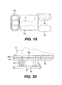
Figures 19 and 20 are a top plan view and side elevational view, respectively, of a different configuration of the apparatus ofFigures 11 and 12 , showing another mode of operation; -
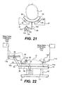
Figure 21 is an end elevational view of a cervical rotation apparatus in accordance with a further embodiment of the invention; -
Figure 22 is a side elevational view of a further modified form of the apparatus ofFigure 1 , providing the addition of traction; -
Figure 23 is a perspective view of the passive range of motion exercise and/or treatment apparatus according to a further embodiment of the invention; and -
Figure 24 is a side elevational view of the apparatus ofFigure 23 , with parts omitted, illustrating an automated reclining feature thereof. - Referring to
Figures 1 to 6 , there is shown a preferred embodiment of the continuous passive motion and traction device of the invention. As indicated inFigure 1 , the device or machine, which is generally denoted 10, includes aframe 12 including an uppermain table member 14 supported bylegs 16 or like supports in a sled configuration formed byparallel support members 18.Wheels 20 mounted on atransverse axle 22 extending between the front ends ofsupport members 18 enable thedevice 10 to be moved. Downwardly depending, adjustable leveling elements orlevelers 24 located at the ends ofsupport members 18 help fix thedevice 10 in place as well as to level the device.Levelers 24 are provided at both ends ofsupport members 18 inFigure 1 and at only one end inFigure 2 and either option can be used. - In the configuration shown in
Figure 1 , the overall support portion ofdevice 10 includes the aforementionedmain table member 14 and a further auxiliary,upper support member 26 which is located adjacent to the foot or distal end ofmain table member 14.Support member 26 is of a smaller size than, and is movable (pivotable) with respect to,table support member 14. In the configuration shown inFigure 1 ,support member 26 is positioned at what would be considered the foot or distal end oftable member 14, and, in this configuration, at the foot ofdevice 10, as shown inFigure 1 . In another configuration, which is used to provide movement of the neck and head of the user,support member 26 is positioned at what would be considered to be the head or proximal end of thedevice 10, as shown inFigure 2 . As described hereinbelow, the particular relative orientation ofsupport member 26 used is dictated by the mode of operation ofdevice 10. - A control panel or
control unit 28 is located beneathmain table member 14, on one side thereof, betweenlegs 16 as indicated inFigures 1 and 2 .Control unit 28 contains an electrical control system for the operating mechanisms described below, including the controls of the simplified control circuit shown inFigures 7 and 8 . It will be appreciated that the control panel or control unit can be a separate unit from the main apparatus and that the control unit can also be connected to an external computer device such as a PC. - An adjustable, self-adjusting lower leg (calf)
support assembly 30 is also provided which can be moved to either end ofdevice 10 in different modes of operation described below.Calf support assembly 30 can also be completely removed from thedevice 10 for shipping or storage.Calf support assembly 30 includes abase member 32 which includes conventional mounting means (not shown) for mountingbase member 32, and thus theentire assembly 30, on eithermain table member 14 as shown inFigure 2 or onauxiliary support member 26 as shown inFigures 1 and6 . The mounting means (not shown) can take a number of different forms and can, for example, comprise a shaped (e.g., square) mounting element (not shown) adapted to be non-rotatably and detachably received in a corresponding slot or sleeve (not shown) provided at the free end of each of thesupport members Support assembly 30 further includes a connecting member or strut 34 and asupport platform 36 which is of a double plate construction in the illustrated embodiment. A pair of mounting elements 38 (seeFigure 1 ) are secured to strutmember 34 by apivot pin 40 so as to enable pivoting ofplatform 36 aboutpivot pin 38, as indicated inFigure 3 . The mounting arrangement forplatform 36 is such that theplatform 36 can be pivoted by corresponding movement of the calves and feet of the user, and thus is readily self-adjusting, yet is still stiff enough that theplatform 36 will remain in the position to which it is moved. Again, the pivotable mounting arrangement is conventional per se and it will be understood by those skilled in the mechanical arts that a number of different pivotable mounting arrangements are suitable for this purpose. - As best seen in
Figures 1 and4 , thetable support member 14 andauxiliary support member 26 include spaced pairs of contouredpads head pillow 42 is disposed betweenpads 14a at one end thereof and a series of removable, replaceable hot and/orcold packs 44 are disposed betweenpads Figure 4 .Pads cold packs 44 are used to apply heat or cold to different parts of the body of the user (e.g., the back and buttocks or the sides and hips) as appropriate to his or her condition and treatment schedule (e.g., whether the application of heat and/or cold is prescribed in connection with a particular exercise or treatment regimen). - As indicated in
Figure 1 , aseat belt 46, or like restraining belt or harness, is preferably provided onauxiliary support member 26 so as to hold the waist and hips in place during certain movements. In addition, in an optional embodiment also shown inFigure 1 , a pair of handle grips or hand grips 48 are provided which extend upwardly and outwardly fromtable member 14 at the end thereof adjacent to supportmember 26 so as to be grippable by a user during certain movements. The hand grips can also be provided on thesupport member 26 and this may be preferable in some applications. - As indicated above,
auxiliary support member 26 is pivotable with respect totable member 14 and, to this end, anupright pivot shaft 50 is provided about which supportmember 26 pivots. As will be understood by those skilled in the mechanical arts, the overall pivoting arrangement can take a number of different conventional forms. For example, a simple arrangement can be used wherein a downwardly dependingportion 52 ofsupport member 26 includes asleeve 52a which is affixed to the dependingportion 52 that facespivot shaft 50 and which fits aroundpivot shaft 50 to enable pivoting ofauxiliary support member 26 relative to tablesupport member 14. - A preferred embodiment of the operating mechanism for pivoting
support member 26 is generally indicated at 54 inFigures 5 and 6 . Theoperating mechanism 54 includes alinkage member 56 which is pivotably connected at one end thereof to aframe portion 26a ofsupport member 26 and at the other end thereof to a travelingnut 58 mounted on a rotatable worm gear or screw 60 rotatably mounted in first and second spacedbushings 62. Gear or screw 60 is driven by agear head motor 64 with aneccentric drive element 66. Rotation ofscrew 60 produces movement of travelingnut 58 therealong, with the direction of rotation ofscrew 60 determining the direction of travel ofnut 58. This movement ofnut 58 produces corresponding movement oflinkage member 56 and thereby causes pivoting ofsupport member 26. - It will, of course, be understood that other operating mechanisms can be used and, in this regard, in another, non-illustrated embodiment, the
eccentric drive element 66 is used to drive a spring biased crank arrangement (not shown). The user can exert a resistive force against the springs (not shown) of this arrangement to provide interactive exercising of the body part in question, and an override feature can be provided, if desired, wherein the user can overpower the machine. It will, of course, be understood that the motor or drive unit that is used in these various embodiments can be other than an electric motor (e.g., a hydraulic motor or the like). - As indicated above, the electronic controls for
motor 64 are housed within control panel orunit 28. As shown inFigure 6 , a remote control, hand operatedswitch device 68 is connected to controlunit 28 by acable 70 so as to enable the operation of thedevice 10 to be controlled by the user during use. In a preferred embodiment,switch device 68 is, or includes, a "kill" switch, i.e., a switch that enables the user to immediately stop operation of thedevice 10, and thus immediately terminate an exercise when, e.g., the user is feeling overtired or is suffering pain. Optionally, other functions, such as motor speed, can also be controlled byswitch device 68. - Referring to
Figure 7 , a schematic circuit diagram of the motor control circuit is shown. The circuit includes a (110 volt)wall plug 72 two leads of which are connected to aspeed control unit 74, with one lead (the B lead) being connected through a "kill"switch 76 and afuse 78. Two output leads fromspeed control unit 74 are connected through abridge rectifier unit 80 to theDC gear motor 64 mentioned above. A ground connection indicated at 82 is preferably made to the frame ofdevice 10 through the mount (not shown) for the fullwave bridge unit 80. - A schematic circuit diagram of
bridge rectifier unit 80 is shown inFigure 8 . As illustrated,unit 80 includes atransformer 82 connected to a full wavediode rectifier bridge 84 comprising diodes D1, D2, D3 and D4. The DC leads frombridge 84 is connected tomotor 64, with the non-grounded lead being connected tomotor 64 through a resistor R. - It will be understood that the control circuitry of
Figures 7 and 8 represents a simplified control approach and, in preferred embodiments, more sophisticated adjustments would be provided for controlling speed, power, duration, volume and like parameters, depending on the nature of the operating mechanism used and the operating features desired. - Referring to
Figures 9 and 10 , there is illustrated a first mode of operation ofdevice 10. In this mode of operation, the user U is positioned in the "90/90" position referred to above, wherein the user U lies horizontally on his or her back ontable member 14 and the lower legs are supported onplatform 36 in a parallel horizontal plane. The buttocks are supported onauxiliary support member 26 in the same horizontal plane as the rest of the body trunk or torso, and both the trunk and lower legs are positioned at an angle of roughly 90° to the substantially vertical upper legs. This "90/90" position is widely regarded as the most comfortable for those with lower back pain. - In the illustrated configuration, the buttocks are, as indicated above, supported on
auxiliary support member 26, with the user U being positioned between hand grips 48.Seat belt 46 is placed around the lower trunk to secure the user U in place. In this position, pivoting ofsupport member 26, as indicated in dashed lines inFigure 9 , provides movement of the lower trunk through a limited range of motion and thus provides gentle exercising of the lower back. Stated differently, pivoting ofsupport member 26 can provide from 0-20° (inclusive) of mechanically assisted lateral side flexion for the lumbar spine. It will be understood that the pivoting motion provided can be through the same angle on both sides, different angles on the two sides or on one side only. The general motion provided is widely accepted as being the most tolerable and potentially the most beneficial to individuals suffering from relatively severe back pain, while not producing user discomfort. - Referring to
Figures 11 and 12 a further mode of operation is shown. In this embodiment, the lower leg (calf)support assembly 30 is not used, and a differentleg support member 86 is provided.Leg support member 86 is adapted to be affixed to supportmember 26 at one side or the other and as in the other embodiment, a contoured pad orcushion 86a is disposed onsupport member 86. The connection betweensupport member 86 andsupport member 26 can take a number of different forms. In one embodiment, this connection can comprise a simple rod and sleeve (or slot) connection wherein a downwardly depending portion of a rod (not shown) mounted on one of the twomembers members leg support member 86 is adapted to be mounted at either side ofsupport member 26 so that the user U can be positioned on either side of his or her body. In the mode of operation illustrated, the user U lies on one side, and the hips and lower trunk together with the legs are pivoted relative to the rest of the body. - Referring to
Figures 13 and 14 , a further mode of operation is illustrated. In this mode of operation, which employs the configuration illustrated inFigure 2 , the leg (calf)support assembly 30 is not affixed to supportmember 26 but is rather affixed to the opposite end oftable support member 14. The user U is thus supported in the "90/90" position as inFigures 9 and 10 but, in contrast to the mode of operation illustrated inFigures 9 and 10 , the neck and head move relative to the remainder of the body through pivoting movement ofsupport member 26, on which the head of the user U rests. - Turning to
Figures 15 and 16 , an embodiment is shown which is somewhat similar to that ofFigures 13 and 14 whereinsupport member 26 is provided with anair bladder device 88 used to provide head movement.Bladder device 88 includes twoair bladders Figure 16 , and are connected byhoses air pump 92 with volume, timer and exhaust controls. Thepump 92 is used to alternately inflate and deflatebladders Figure 14 and the neck thus exercised by this movement. This can be done in lieu of, or in conjunction with, pivoting movement of thesupport member 26, depending on the exercise regimen appropriate for the particular user. - Referring to
Figures 17 and 18 , an embodiment is shown which is similar to that ofFigures 14 and15 but in which, instead of thebladder arrangement 88 being used to support the head and neck, thebladder arrangement 88 is used to support the lower trunk. As shown, the leg (calf)support assembly 30 is located at the other end of thedevice 10 so that the lower trunk rests onpad 26a provided onsupport member 26. This arrangement permits the hips to be rotated as indicated in dashed lines inFigure 17 by alternatively inflating and deflatingbladders - In a non-illustrated embodiment, a further bladder or expandable section (not shown) is provided which is disposed so as to be positioned under, e.g., the upper back of a user between the shoulder blades. The further bladder (not shown) would be inflated and deflated alternately with a neck supporting bladder to provide a gentle rocking motion.
- In order to prevent overinflation of a bladder in a situation where a bladder is partially inflated when the machine is turned off (and thus subject to being overinflated when the machine is turned on again and thus the pressure necessary to provide normal full inflation is applied), in accordance with a further, non-illustrated embodiment, the bladders are automatically deflated when the machine is turned off by means, e.g., of a solenoid-controlled actuator providing such deflation.
- Referring to
Figures 19 and 20 , an embodiment similar to that ofFigures 11 and 12 is shown. In this embodiment, aleg support member 93, corresponding toleg support member 86 ofFigures 11 and 12 , is affixed totable member 14, rather thanauxiliary support member 26 as inFigures 11 and 12 , and is used to support the legs of user U while the head and neck are moved by pivoting ofsupport member 26 while the user U lies on one side. As indicated inFigure 18 and was discussed above in connection withFigures 11 and 12 ,leg support member 93 can be positioned at either side oftable member 14 so as to permit the user to lie on either side. - Referring now to
Figure 21 , a further embodiment is shown which is used in providing movement of the head of a user, viz., in providing rotation of the neck or cervix. Acervical support member 94 of a shallow U-shape is used to support the head and neck.Member 94 is supported by, and rolls on,roller bearings 95 which are, in turn, supported in bearingraces 96 defined by spaced supports 97. Rotational movement ofsupport member 94 take place under the control of acontrol mechanism 98.Control mechanism 98 includes a link orarm 100 rigidly affixed to supportmember 94, a drive orcontrol arm 102 connected to themotor drive shaft 104 of amotor 105 and alinking arm 106 pivotably connected toarms Control mechanism 98 produces limited rotation ofsupport member 94 so as to gently rotate and exercise the neck. - Turning to
Figure 22 , an embodiment is shown which basically corresponds to that ofFigure 6 andFigures 9, 10 but includes a traction arrangement for keeping a user U in traction during the passive movements provided by the device 10 (in this case, movement of the lower trunk and legs). It will, of course, be appreciated that traction can also be provided with other embodiments described above and that other traction arrangements can be used as well. InFigure 22 , both a lumbartraction control device 108 and acervical traction control 110 are provided. As indicated schematically inFigure 22 ,suitable pulleys 112, andseparate harnesses - The passive range of motion control provided by
device 10 can be provided on continuous duty basis, with low maintenance requirements and the need for only very occasional lubrication. The mechanisms used afford a very smooth operation, and linear actuators employed preferably have a stroke length of about 12,5 or 15 cm (5" or 6"). The force exerted is preferably no greater than about 23 kg (50 lbs). - The
control unit 28 is adapted to provide push button programmable motion, and is preferably programmable to nine ranges of motion as follows (in degrees): 10-7½-5-2½0-2½-5-7½-10. The timer used is also programmable, preferably from fifteen minutes to eight hours, and is set to automatically return to zero when the timer times out. - The frame construction of at least the embodiments described above permits the apparatus to be stood on end for storage in a closet or other small area.
- The
control unit 28 preferably includes an A/B switch or other switching device (not shown) for switching between the linear actuator control (shown, e.g., inFigures 5 and 6 ) and the pneumatic pump control (Figures 15, 16 and 17, 18 ). - Referring to
Figures 23 and 24 , there is shown a further embodiment of the invention which is particularly adapted for clinical use. This embodiment is similar to that ofFigure 1 but there are both major and minor differences. The apparatus, which is generally denoted 94', includes a base cabinet 96' land a base 98' formed by two pairs of horizontally extending support legs 100' extending outwardly from cabinet 96' on opposite sides thereof. Levelers 102' corresponding to those described above, are provided at the free ends of support legs 100' A control unit including an external control panel or controls indicated at 104' is housed within cabinet 96'. The overall height of apparatus 94' is greater than that of the apparatus ofFigure 1 for reasons which will become apparent. - The apparatus 94' includes a first (table) support member 106' which is similar to that described above and which has seated thereon a body support pad or cushion arrangement 108'. In the embodiment illustrated, the latter includes a pair of spaced, laterally disposed contoured
pads 108a, and acentral head rest 108b in alignment with a pair of heating and/or coolingunits 108c, all as described previously. - A second support member 110' is pivotably connected to support member 106' and is controllably pivoted relative thereto, as described above, under the control of control panel 104'. Support member 110' includes a contoured covering pad or cushion 112' seated thereon, and affixed thereto, as shown.
- A further, separate seat member 114' is affixed to second support member 110' and moves therewith. As shown in
Figure 23 , seat member 114' may include laterally disposed, outwardly extending arms 116' at opposite sides thereof which are adapted to be gripped by a user. - A lower leg (calf) support member 118' is affixed to seat member 114' by a support strut 120' and is pivoted in a self-adjusting manner with respect to strut 120', as was described above in connection with
Figure 1 and the related drawing figures. - An important feature of the embodiment of
Figures 23 and 24 is that, in this embodiment, a reclining functionality is provided wherein, in use of the apparatus 94', the user is first seated on the apparatus or machine in an upright seated position and is then reclined, i.e., passively moved to a reclining 90/90 position, without any effort on his or her part. It will be appreciated that this feature can be of substantial importance in dealing with a seriously ill or infirmed person in that the person does not have to climb onto the machine or be placed on the machine, thereby avoiding stresses that might ordinarily occur with such placement. The first support member 106', second support member 110', seat member 114', and leg support 118' all form a unitary body support unit or construction that is pivotable with respect to base cabinet 96' about a pivot axis. (InFigure 24 , a single seat member 114', which is disposed at a right angle with respect to first support member 106', replaces members 110' and 114' ofFigure 23 , for purposes of simplicity.) With the provision of such a pivotable unitary construction, it will be appreciated that, referring toFigure 24 , by effecting simple pivoting of this unitary construction or unit about the pivot point, a user can be moved from the position indicated at A inFigure 24 wherein the user is seated on seat member 114' with the backs of the lower portions of his or her legs against leg support 118', and his or her back againstfirst support member 106, through an intermediate position, indicated at B, to a final inclined, "90/90" treatment position, indicated at C, wherein the back of the user rests on support member 106', his or her buttocks abut against seat member 114' and the legs rest on leg support 118'. Thus, the entire body support (including the linkage mechanism (not shown) which provides the relative lateral pivoting between sections of the body support as described above) pivots or tilts through 90° relative to the base cabinet 96' and base support 98', which remain stationary. - Although it will be appreciated that a number of different control mechanisms can be used to provide this pivoting or tilting motion, in one preferred embodiment, a linear actuator (not shown), advantageously in the form of an electro-mechanically activated lead screw device (not shown), would be used. However, again, any conventional control mechanism that is capable of providing smooth controlled pivoting of the body support unit in the manner described would be a suitable candidate for this purpose.
- It will be appreciated from the foregoing that the invention is able to provide a large number of different motions. These motions include: lateral side flexion for the lumbar spine; lateral side flexion for the cervical spine; pelvic tilt and rotation; cervical rotation; extension of the trunk; flexion of the trunk; cervical flexion; cervical extension; lumbar distraction; resistive, i.e., interactive exercises for all of the above; and cervical traction. In addition to these motions, the
device 10 provides comfortable support of a user while in a static or motionless mode. As indicated above in connection withFigure 22 , the apparatus can be retrofitted with cervical and other traction devices. - Although the invention has been described above in relation to preferred embodiments thereof, it will be understood by those skilled in the art that variations and modifications can be effected in these preferred embodiments without departing from the scope of the invention as defined in the appended claims.
Claims (4)
- A passive motion apparatus, said apparatus comprising:a main support assembly (10) for supporting at least part of the body of a user of the apparatus and including
a first support member (14) providing, in use, a substantially horizontal support surface defining a plane anda second support member (26) providing, in use, a substantially horizontal support surface disposed in said plane, said second support member (26) being pivotable relative to said first support member (14) and being movable relative thereto such that movement of the second support member (26) with respect to the first support member (14) provides passive movement of a part of the body of a user supported by said second support member (26) relative to a part of the body supported by said first support member (14); andmotorized drive means (56-66) for, when activated, providing said movement of said second support member relative to said first support member to provide continuous passive movement of the part of the body supported by said second member; anda leg support assembly (30) connected to said second support member (26) of the main support assembly (10) for supporting, in use, at least part of the legs of the user; characterised in that said leg support assembly (30) includes a support platform (36) and a support strut (34) for supporting said platform (36) in a plane elevated with respect to the first-mentioned plane such that lower portions of the legs of the user are elevated with respect to the remainder of the body of the user and such that upper portions of the legs of the user extend at substantially right angles with respect to the lower portions of the legs and the trunk of the body of the user;wherein said leg support assembly (30) further includes means for pivotably mounting said support platform (36) with respect to said support strut (34) so as to enable angular adjustment of the support platform (36) about the support strut (34). - The passive motion apparatus of claim 1, wherein:said first support member, in use, supports a back portion of the head of the user;said second support member, in use, supports the lower trunk of the user;said motorized drive means, when activated, provides pivotable movement of said second support member about a vertical pivot axis between first and second end positions so as to provide continuous passive motion of at least the lower trunk of the user; andsaid vertical pivot axis is disposed at an end of said second support member adjacent to said first support member and is equispaced from opposed edges of said second support member.
- A passive motion apparatus in accordance with claim 1 or 2 further comprising a safety belt affixed to said second support member.
- A passive motion apparatus in accordance with any preceding claim further comprising a pair of laterally spaced hand grips affixed to one end of said first support member.
Applications Claiming Priority (3)
| Application Number | Priority Date | Filing Date | Title |
|---|---|---|---|
| US10/042,389 US6692451B2 (en) | 2002-01-11 | 2002-01-11 | Passive motion apparatus providing a controlled range of motion |
| US42389 | 2002-01-11 | ||
| PCT/US2003/000365 WO2003059278A2 (en) | 2002-01-11 | 2003-01-08 | Passive motion apparatus providing a controlled range of motion |
Related Child Applications (1)
| Application Number | Title | Priority Date | Filing Date |
|---|---|---|---|
| EP13164762.0 Division-Into | 2013-04-22 |
Publications (3)
| Publication Number | Publication Date |
|---|---|
| EP1471864A2 EP1471864A2 (en) | 2004-11-03 |
| EP1471864A4 EP1471864A4 (en) | 2008-12-10 |
| EP1471864B1 true EP1471864B1 (en) | 2013-08-14 |
Family
ID=21921657
Family Applications (1)
| Application Number | Title | Priority Date | Filing Date |
|---|---|---|---|
| EP03702024.5A Expired - Lifetime EP1471864B1 (en) | 2002-01-11 | 2003-01-08 | Passive motion apparatus providing a controlled range of motion |
Country Status (6)
| Country | Link |
|---|---|
| US (1) | US6692451B2 (en) |
| EP (1) | EP1471864B1 (en) |
| JP (1) | JP4436133B2 (en) |
| AU (1) | AU2003202912C1 (en) |
| CA (1) | CA2474928A1 (en) |
| WO (1) | WO2003059278A2 (en) |
Cited By (1)
| Publication number | Priority date | Publication date | Assignee | Title |
|---|---|---|---|---|
| CN109475461A (en) * | 2016-07-14 | 2019-03-15 | 石黑隆 | The articulatio sacroiliaca assistant device for sport tool of lateral position |
Families Citing this family (53)
| Publication number | Priority date | Publication date | Assignee | Title |
|---|---|---|---|---|
| WO2004058124A2 (en) * | 2002-12-16 | 2004-07-15 | Cert Health Sciences, Llc | Method and apparatus for therapeutic treatment of back pain |
| US20040158176A1 (en) * | 2003-01-29 | 2004-08-12 | Joon Park | Hot acupressure and massage machine |
| US7448984B2 (en) * | 2003-12-23 | 2008-11-11 | Loyal Chow | Passive exercise apparatus |
| US7341565B2 (en) * | 2004-04-02 | 2008-03-11 | Suncepts, Inc. | Passive motion machine providing controlled body motions for exercise and therapeutic purposes |
| JP2006263051A (en) * | 2005-03-23 | 2006-10-05 | Daisuke Otsuka | Bed-shaped exerciser |
| US7371221B1 (en) | 2004-08-10 | 2008-05-13 | Baker Ford S | Cervical brace and therapy device |
| US7608052B1 (en) | 2004-08-10 | 2009-10-27 | Baker Ford S | Cervical brace and therapy device |
| US7727119B2 (en) * | 2004-09-27 | 2010-06-01 | Therapease Innovation, Llc | Human self-powered joint exerciser apparatus |
| WO2006097921A2 (en) * | 2005-03-14 | 2006-09-21 | Backlife Ltd. | Device and method for treating neck tension or neck injury |
| US20060272893A1 (en) * | 2005-05-26 | 2006-12-07 | Joe Foggio | Therapeutic foot/leg/knee elevation |
| KR100630260B1 (en) * | 2005-08-22 | 2006-10-02 | 경북대학교 산학협력단 | Rehabilitation Equipment for Lower Limb and Rehabilitation Method of the same |
| US20070161479A1 (en) * | 2006-01-10 | 2007-07-12 | Harris Donald T | Knee-stretching Device and Treatment Methods |
| FR2903886B1 (en) * | 2006-07-19 | 2008-10-03 | Down Cost Engineering Sarl | DEVICE FOR STRETCHING THE VERTEBRAL COLUMN OF A PERSON |
| WO2008059497A2 (en) | 2006-11-15 | 2008-05-22 | Headway Ltd. | Dynamic cradle, especially for treating head and neck pain |
| US8021287B2 (en) | 2007-04-25 | 2011-09-20 | Backproject Corporation | Restraint, reposition, traction and exercise device and method |
| ITPI20070063A1 (en) * | 2007-05-28 | 2008-11-29 | Donati S R L | AUTONOMOUS EXECUTION MACHINE FOR PHYSIOTHERAPY EXERCISES. |
| US20090024164A1 (en) * | 2007-06-25 | 2009-01-22 | Neubardt Seth L | System for determining spinal implants |
| US20110092859A1 (en) | 2007-06-25 | 2011-04-21 | Neubardt Seth L | System for determining and placing spinal implants or prostheses |
| US9009894B2 (en) * | 2007-09-20 | 2015-04-21 | Posture Correction Tools, LLC | Chiropractic posture correction tool |
| CH701932B1 (en) * | 2008-01-03 | 2011-04-15 | Clemens Dr Med Gutknecht | Patient bed with monitoring and therapy device. |
| ES1067066Y (en) * | 2008-01-18 | 2008-07-16 | Jean Claude Hirt | MUSCLE RELAXATION DEVICE |
| US20090255543A1 (en) * | 2008-04-14 | 2009-10-15 | Masumi Oyama | Method of chiropractic treatment |
| WO2009137474A1 (en) * | 2008-05-06 | 2009-11-12 | Dicerbo Mary T M | System and method for treating cervical vertebrae |
| HUE047505T2 (en) * | 2008-05-29 | 2020-04-28 | Jilin Zhang | Spinal three-dimensional orthopaedic equipment |
| IT1398506B1 (en) * | 2008-11-18 | 2013-03-01 | S P A S S R L | BED FOR REHABILITATION |
| US7951097B2 (en) * | 2009-06-15 | 2011-05-31 | Schaeffer Dwight L | Automated therapy table for treating lower extremities and method therefor |
| US8382692B1 (en) | 2010-06-10 | 2013-02-26 | John Chao | Neck and spine support device for a neck in flexion |
| US8287439B2 (en) | 2010-07-19 | 2012-10-16 | Evans Joseph W | Self-operating back stretching device |
| DE102011050194A1 (en) * | 2011-05-06 | 2012-11-08 | Dewert Antriebs- Und Systemtechnik Gmbh | Electromotive furniture drive with a power supply device |
| US9345611B2 (en) | 2011-05-11 | 2016-05-24 | Backproject Corporation | Cervical repositioning, restraint, traction and exercise device and method |
| FR2985195A1 (en) * | 2012-01-02 | 2013-07-05 | Kang Jun Yim | Sporting apparatus for exercising lumbar and viscera, has controller for controlling temperature of thermo-mat, speed and duration of rotation of rotational panel unit, and angle of rotation of rotational panel unit |
| US20130261510A1 (en) * | 2012-04-03 | 2013-10-03 | Ergo-Flex Technologies, LLC | Reclinable therapeutic massage chair |
| KR101415105B1 (en) | 2012-04-12 | 2014-07-11 | 주식회사 씨에스테크놀로지 | Machine for exercising and medical treating for whole body by bending body right and left |
| US9498397B2 (en) | 2012-04-16 | 2016-11-22 | Allen Medical Systems, Inc. | Dual column surgical support system |
| JP5542170B2 (en) * | 2012-05-16 | 2014-07-09 | 大東電機工業株式会社 | Lumbar exercise machine |
| US9205015B2 (en) * | 2012-07-25 | 2015-12-08 | Lawrence Guillen | Linear motion therapy device |
| US9662260B2 (en) * | 2013-11-22 | 2017-05-30 | Paulo Sergio BERVIAN | Device for passive body mobilization |
| RU2545444C1 (en) * | 2013-12-13 | 2015-03-27 | Общество с ограниченной ответственностью "Белмединновация" | Method of treating and preventing neurological, cardiological and therapeutical conditions |
| CN105596133A (en) * | 2014-11-14 | 2016-05-25 | 何少敦 | Soft slide cloth pad for vertebral body traction bed and vertebral body traction bed with soft slide cloth pad |
| CN104757943B (en) * | 2015-04-21 | 2018-08-10 | 中国人民解放军空军航空医学研究所 | A kind of multifunctional medical tilt table |
| US10548793B2 (en) | 2016-06-14 | 2020-02-04 | Allen Medical Systems, Inc. | Pinless loading for spine table |
| US10857052B1 (en) * | 2016-08-31 | 2020-12-08 | Pivotal Health Solutions, Inc. | Treatment table for therapeutic treatment, physical rehabilitation and training and method of use |
| US10065072B2 (en) * | 2016-09-06 | 2018-09-04 | Tao Xu | Lower back exercise apparatus |
| CA3042578A1 (en) | 2016-11-07 | 2018-05-11 | Neck Tronics Inc. | Devices and methods for exercise or analysis of the neck region |
| WO2018140823A1 (en) * | 2017-01-26 | 2018-08-02 | ScoliWRx Inc. | Stretching table and method |
| CN106955214B (en) * | 2017-04-10 | 2018-06-22 | 林发绍 | It is a kind of to be suitable for the medical care bed of CPR |
| RU2657375C1 (en) * | 2017-04-27 | 2018-06-13 | Общество с ограниченной ответственностью "Белмединновация" | Simulator for improving microcirculation of human blood |
| PL233326B1 (en) * | 2017-09-12 | 2019-09-30 | Politechnika Rzeszowska Im Ignacego Lukasiewicza | Device for rehabilitation of lower limbs |
| PL233327B1 (en) * | 2017-09-12 | 2019-09-30 | Politechnika Rzeszowska Im Ignacego Lukasiewicza | Device for rehabilitation of lower limbs |
| US11844738B2 (en) | 2018-08-17 | 2023-12-19 | Troy Bruesewitz | Therapy device for neck and spine |
| US11497669B2 (en) * | 2019-04-27 | 2022-11-15 | Ethicon, Inc. | Systems, devices, and methods for testing suture performance under static and dynamic conditions |
| JP7450889B2 (en) | 2021-06-11 | 2024-03-18 | ミナト医科学株式会社 | trunk exercise device |
| KR102639123B1 (en) * | 2021-09-27 | 2024-02-20 | 김승준 | Braces for neck exercise massage |
Family Cites Families (27)
| Publication number | Priority date | Publication date | Assignee | Title |
|---|---|---|---|---|
| US3124126A (en) * | 1964-03-10 | spinks | ||
| US2872259A (en) * | 1956-11-26 | 1959-02-03 | Allen & Hanburys Ltd | Operation tables having removably supported interchangeable head and leg extension sections |
| DE1210476B (en) * | 1959-12-31 | |||
| US3238936A (en) * | 1962-04-16 | 1966-03-08 | Nat Foundation For Physical Me | Apparatus for mechanical corrective therapy |
| US3620210A (en) * | 1969-03-21 | 1971-11-16 | Paramount Health Equip Corp | Sacroiliac rotator |
| US3674017A (en) | 1971-03-15 | 1972-07-04 | Hugo Stefani Jr | Apparatus for passively exercising a person{40 s abdominal muscles |
| US4144880A (en) | 1977-03-11 | 1979-03-20 | Daniels E Robert | Orthopedic table |
| US4373222A (en) * | 1980-01-28 | 1983-02-15 | Enhancement Systems, Inc. | Prosthetic bench |
| US4649905A (en) * | 1984-11-01 | 1987-03-17 | Barnes James E | Cervically adjustable chiropractic treatment table |
| US5035234A (en) | 1988-08-11 | 1991-07-30 | Forsythe Kenneth D | Method for functional evaluation and exercising the back muscles of a person |
| US4953541A (en) | 1988-09-16 | 1990-09-04 | Parker Jr Alonzo E | Interchangeable passive exercising apparatus |
| US4827913A (en) | 1988-09-16 | 1989-05-09 | Parker Alonzo E | Passive exercising apparatus |
| US5044359A (en) | 1990-06-12 | 1991-09-03 | Reinert Otto C | Passive spinal extension device |
| US5258019A (en) * | 1991-01-14 | 1993-11-02 | United Apothecary, Inc. | Lumbar spine therapy device |
| US5123916A (en) | 1991-01-14 | 1992-06-23 | United Apothecary, Inc. | Lumbar spine therapy device |
| US5308359A (en) * | 1991-06-24 | 1994-05-03 | Lossing Orthopedic, Inc. | Apparatus and method for producing spinal distraction |
| US5171260A (en) | 1991-07-31 | 1992-12-15 | Mcilwain William A | Passive body-motion generating apparatus and procedure |
| US5500002A (en) | 1992-02-28 | 1996-03-19 | United Apothecary, Inc. | Continous passive motion physical therapy device |
| US5320641A (en) | 1992-02-28 | 1994-06-14 | Riddle & Withrow, Inc. | Computer controlled physical therapy device |
| US5282835A (en) * | 1992-03-04 | 1994-02-01 | Wright Howard S | Exercising table for applying cyclic movement with adjustable support members |
| US5300090A (en) * | 1992-09-03 | 1994-04-05 | Challenge Machinery (Proprietary) Ltd. | Exercise machine |
| US5423862A (en) * | 1993-01-29 | 1995-06-13 | Mediflex Systems, Inc. | Orthopedic treatment apparatus |
| US5926002A (en) * | 1995-02-21 | 1999-07-20 | Getinge/Castle, Inc. | Pendent with safety features for patient handling apparatus |
| US6086550A (en) | 1995-07-21 | 2000-07-11 | Richardson; Ronald L. | Apparatus for imparting a rocking motion to the legs and torso of a user |
| ES2133215B1 (en) * | 1996-04-15 | 2000-03-01 | Cobo Bernabe Cobo | PHYSIOTHERAPY APPARATUS FOR THE TREATMENT OF ARTICULAR RIGIDITY. |
| ATE245397T1 (en) * | 1997-11-07 | 2003-08-15 | Hill Rom Co Inc | THERMAL CONTROL SYSTEM FOR PATIENTS |
| US6302859B1 (en) | 2000-04-04 | 2001-10-16 | Ralph B. Cushman | Traction device |
-
2002
- 2002-01-11 US US10/042,389 patent/US6692451B2/en not_active Expired - Lifetime
-
2003
- 2003-01-08 AU AU2003202912A patent/AU2003202912C1/en not_active Ceased
- 2003-01-08 CA CA002474928A patent/CA2474928A1/en not_active Abandoned
- 2003-01-08 JP JP2003559443A patent/JP4436133B2/en not_active Expired - Fee Related
- 2003-01-08 EP EP03702024.5A patent/EP1471864B1/en not_active Expired - Lifetime
- 2003-01-08 WO PCT/US2003/000365 patent/WO2003059278A2/en active Application Filing
Cited By (1)
| Publication number | Priority date | Publication date | Assignee | Title |
|---|---|---|---|---|
| CN109475461A (en) * | 2016-07-14 | 2019-03-15 | 石黑隆 | The articulatio sacroiliaca assistant device for sport tool of lateral position |
Also Published As
| Publication number | Publication date |
|---|---|
| AU2003202912A1 (en) | 2003-07-30 |
| US20030135137A1 (en) | 2003-07-17 |
| EP1471864A2 (en) | 2004-11-03 |
| AU2003202912A2 (en) | 2003-07-30 |
| JP2005514986A (en) | 2005-05-26 |
| CA2474928A1 (en) | 2003-07-24 |
| US6692451B2 (en) | 2004-02-17 |
| JP4436133B2 (en) | 2010-03-24 |
| AU2003202912B2 (en) | 2008-10-23 |
| AU2003202912C1 (en) | 2009-08-20 |
| WO2003059278A2 (en) | 2003-07-24 |
| EP1471864A4 (en) | 2008-12-10 |
| WO2003059278A3 (en) | 2003-10-16 |
Similar Documents
| Publication | Publication Date | Title |
|---|---|---|
| EP1471864B1 (en) | Passive motion apparatus providing a controlled range of motion | |
| US7341565B2 (en) | Passive motion machine providing controlled body motions for exercise and therapeutic purposes | |
| US6599257B2 (en) | Cervical therapy device | |
| US5217487A (en) | Back therapy system | |
| KR100518154B1 (en) | Apparatus for restoring the balance of the human body | |
| JP5259629B2 (en) | Training equipment for the disabled | |
| US4915101A (en) | Rotatable treatment table having adjustable support assemblies | |
| US20180078816A1 (en) | Rehabilitation robot integrated with patient mobility and transfer | |
| US7074166B2 (en) | Exercise apparatus and method | |
| US7452308B2 (en) | Cross-crawl chair | |
| US5782869A (en) | Multi-trauma therapeutic machine | |
| US4936573A (en) | Exercise machine with handle assemblies which are linked to pivoting foot pads | |
| US6019740A (en) | Actuator driven stretching and exercise device | |
| US20130289464A1 (en) | Apparatus and method for therapeutic spinal treatment | |
| JP2001212163A (en) | Special traction treatment device | |
| EP2994206B1 (en) | The device for general and sports physiotherapy | |
| KR102001346B1 (en) | Manual Reversing Machine with Reverse Motion | |
| CN112847316A (en) | Supportable lower limb assistance exoskeleton | |
| US10278856B1 (en) | Back traction device | |
| JP4575711B2 (en) | Electric training machine | |
| KR101936671B1 (en) | Remedial exercise device for rotator cuff | |
| CA1210787A (en) | Exercise device | |
| US20070049474A1 (en) | Training apparatus | |
| KR20090121050A (en) | Cycling apparatus for the rehabilitation of the legs | |
| WO2023275625A1 (en) | A device for lumbar and knee recovery |
Legal Events
| Date | Code | Title | Description |
|---|---|---|---|
| PUAI | Public reference made under article 153(3) epc to a published international application that has entered the european phase |
Free format text: ORIGINAL CODE: 0009012 |
|
| 17P | Request for examination filed |
Effective date: 20040806 |
|
| AK | Designated contracting states |
Kind code of ref document: A2 Designated state(s): AT BE BG CH CY CZ DE DK EE ES FI FR GB GR HU IE IT LI LU MC NL PT SE SI SK TR |
|
| AX | Request for extension of the european patent |
Extension state: AL LT LV MK RO |
|
| A4 | Supplementary search report drawn up and despatched |
Effective date: 20081106 |
|
| 17Q | First examination report despatched |
Effective date: 20110411 |
|
| RAP1 | Party data changed (applicant data changed or rights of an application transferred) |
Owner name: SPLANE, ROBSON L. |
|
| GRAP | Despatch of communication of intention to grant a patent |
Free format text: ORIGINAL CODE: EPIDOSNIGR1 |
|
| GRAS | Grant fee paid |
Free format text: ORIGINAL CODE: EPIDOSNIGR3 |
|
| GRAA | (expected) grant |
Free format text: ORIGINAL CODE: 0009210 |
|
| AK | Designated contracting states |
Kind code of ref document: B1 Designated state(s): AT BE BG CH CY CZ DE DK EE ES FI FR GB GR HU IE IT LI LU MC NL PT SE SI SK TR |
|
| REG | Reference to a national code |
Ref country code: GB Ref legal event code: FG4D |
|
| REG | Reference to a national code |
Ref country code: CH Ref legal event code: EP Ref country code: AT Ref legal event code: REF Ref document number: 626345 Country of ref document: AT Kind code of ref document: T Effective date: 20130815 |
|
| REG | Reference to a national code |
Ref country code: IE Ref legal event code: FG4D |
|
| REG | Reference to a national code |
Ref country code: DE Ref legal event code: R096 Ref document number: 60344713 Country of ref document: DE Effective date: 20131010 |
|
| REG | Reference to a national code |
Ref country code: AT Ref legal event code: MK05 Ref document number: 626345 Country of ref document: AT Kind code of ref document: T Effective date: 20130814 Ref country code: NL Ref legal event code: VDEP Effective date: 20130814 |
|
| PG25 | Lapsed in a contracting state [announced via postgrant information from national office to epo] |
Ref country code: CY Free format text: LAPSE BECAUSE OF FAILURE TO SUBMIT A TRANSLATION OF THE DESCRIPTION OR TO PAY THE FEE WITHIN THE PRESCRIBED TIME-LIMIT Effective date: 20130703 Ref country code: AT Free format text: LAPSE BECAUSE OF FAILURE TO SUBMIT A TRANSLATION OF THE DESCRIPTION OR TO PAY THE FEE WITHIN THE PRESCRIBED TIME-LIMIT Effective date: 20130814 Ref country code: PT Free format text: LAPSE BECAUSE OF FAILURE TO SUBMIT A TRANSLATION OF THE DESCRIPTION OR TO PAY THE FEE WITHIN THE PRESCRIBED TIME-LIMIT Effective date: 20131216 Ref country code: SE Free format text: LAPSE BECAUSE OF FAILURE TO SUBMIT A TRANSLATION OF THE DESCRIPTION OR TO PAY THE FEE WITHIN THE PRESCRIBED TIME-LIMIT Effective date: 20130814 |
|
| PG25 | Lapsed in a contracting state [announced via postgrant information from national office to epo] |
Ref country code: GR Free format text: LAPSE BECAUSE OF FAILURE TO SUBMIT A TRANSLATION OF THE DESCRIPTION OR TO PAY THE FEE WITHIN THE PRESCRIBED TIME-LIMIT Effective date: 20131115 Ref country code: BE Free format text: LAPSE BECAUSE OF FAILURE TO SUBMIT A TRANSLATION OF THE DESCRIPTION OR TO PAY THE FEE WITHIN THE PRESCRIBED TIME-LIMIT Effective date: 20130814 Ref country code: FI Free format text: LAPSE BECAUSE OF FAILURE TO SUBMIT A TRANSLATION OF THE DESCRIPTION OR TO PAY THE FEE WITHIN THE PRESCRIBED TIME-LIMIT Effective date: 20130814 Ref country code: SI Free format text: LAPSE BECAUSE OF FAILURE TO SUBMIT A TRANSLATION OF THE DESCRIPTION OR TO PAY THE FEE WITHIN THE PRESCRIBED TIME-LIMIT Effective date: 20130814 |
|
| PG25 | Lapsed in a contracting state [announced via postgrant information from national office to epo] |
Ref country code: CY Free format text: LAPSE BECAUSE OF FAILURE TO SUBMIT A TRANSLATION OF THE DESCRIPTION OR TO PAY THE FEE WITHIN THE PRESCRIBED TIME-LIMIT Effective date: 20130814 |
|
| PG25 | Lapsed in a contracting state [announced via postgrant information from national office to epo] |
Ref country code: DK Free format text: LAPSE BECAUSE OF FAILURE TO SUBMIT A TRANSLATION OF THE DESCRIPTION OR TO PAY THE FEE WITHIN THE PRESCRIBED TIME-LIMIT Effective date: 20130814 Ref country code: SK Free format text: LAPSE BECAUSE OF FAILURE TO SUBMIT A TRANSLATION OF THE DESCRIPTION OR TO PAY THE FEE WITHIN THE PRESCRIBED TIME-LIMIT Effective date: 20130814 Ref country code: NL Free format text: LAPSE BECAUSE OF FAILURE TO SUBMIT A TRANSLATION OF THE DESCRIPTION OR TO PAY THE FEE WITHIN THE PRESCRIBED TIME-LIMIT Effective date: 20130814 Ref country code: EE Free format text: LAPSE BECAUSE OF FAILURE TO SUBMIT A TRANSLATION OF THE DESCRIPTION OR TO PAY THE FEE WITHIN THE PRESCRIBED TIME-LIMIT Effective date: 20130814 Ref country code: CZ Free format text: LAPSE BECAUSE OF FAILURE TO SUBMIT A TRANSLATION OF THE DESCRIPTION OR TO PAY THE FEE WITHIN THE PRESCRIBED TIME-LIMIT Effective date: 20130814 |
|
| RAP2 | Party data changed (patent owner data changed or rights of a patent transferred) |
Owner name: SPLANE, ROBSON L. |
|
| PG25 | Lapsed in a contracting state [announced via postgrant information from national office to epo] |
Ref country code: ES Free format text: LAPSE BECAUSE OF FAILURE TO SUBMIT A TRANSLATION OF THE DESCRIPTION OR TO PAY THE FEE WITHIN THE PRESCRIBED TIME-LIMIT Effective date: 20130814 |
|
| PLBE | No opposition filed within time limit |
Free format text: ORIGINAL CODE: 0009261 |
|
| STAA | Information on the status of an ep patent application or granted ep patent |
Free format text: STATUS: NO OPPOSITION FILED WITHIN TIME LIMIT |
|
| REG | Reference to a national code |
Ref country code: DE Ref legal event code: R081 Ref document number: 60344713 Country of ref document: DE Owner name: SPLANE JR., ROBSON L., VALLEY CENTER, US Free format text: FORMER OWNER: SPLANE, ROBSON L., GRANADA HILLS, CALIF., US Effective date: 20140605 Ref country code: DE Ref legal event code: R082 Ref document number: 60344713 Country of ref document: DE Representative=s name: MAUCHER BOERJES JENKINS, DE Effective date: 20140605 Ref country code: DE Ref legal event code: R081 Ref document number: 60344713 Country of ref document: DE Owner name: SPLANE JR., ROBSON L., VALLEY CENTER, US Free format text: FORMER OWNER: SUNCEPTS INC., STUART, FLA., US Effective date: 20130816 Ref country code: DE Ref legal event code: R082 Ref document number: 60344713 Country of ref document: DE Representative=s name: MAUCHER JENKINS, DE Effective date: 20140605 Ref country code: DE Ref legal event code: R082 Ref document number: 60344713 Country of ref document: DE Representative=s name: MAUCHER JENKINS PATENTANWAELTE & RECHTSANWAELT, DE Effective date: 20140605 |
|
| 26N | No opposition filed |
Effective date: 20140515 |
|
| REG | Reference to a national code |
Ref country code: DE Ref legal event code: R097 Ref document number: 60344713 Country of ref document: DE Effective date: 20140515 |
|
| PG25 | Lapsed in a contracting state [announced via postgrant information from national office to epo] |
Ref country code: MC Free format text: LAPSE BECAUSE OF FAILURE TO SUBMIT A TRANSLATION OF THE DESCRIPTION OR TO PAY THE FEE WITHIN THE PRESCRIBED TIME-LIMIT Effective date: 20130814 Ref country code: LU Free format text: LAPSE BECAUSE OF FAILURE TO SUBMIT A TRANSLATION OF THE DESCRIPTION OR TO PAY THE FEE WITHIN THE PRESCRIBED TIME-LIMIT Effective date: 20140108 |
|
| REG | Reference to a national code |
Ref country code: CH Ref legal event code: PL |
|
| PG25 | Lapsed in a contracting state [announced via postgrant information from national office to epo] |
Ref country code: CH Free format text: LAPSE BECAUSE OF NON-PAYMENT OF DUE FEES Effective date: 20140131 Ref country code: LI Free format text: LAPSE BECAUSE OF NON-PAYMENT OF DUE FEES Effective date: 20140131 |
|
| REG | Reference to a national code |
Ref country code: IE Ref legal event code: MM4A |
|
| PG25 | Lapsed in a contracting state [announced via postgrant information from national office to epo] |
Ref country code: IE Free format text: LAPSE BECAUSE OF NON-PAYMENT OF DUE FEES Effective date: 20140108 |
|
| REG | Reference to a national code |
Ref country code: FR Ref legal event code: PLFP Year of fee payment: 14 |
|
| PG25 | Lapsed in a contracting state [announced via postgrant information from national office to epo] |
Ref country code: BG Free format text: LAPSE BECAUSE OF FAILURE TO SUBMIT A TRANSLATION OF THE DESCRIPTION OR TO PAY THE FEE WITHIN THE PRESCRIBED TIME-LIMIT Effective date: 20130814 |
|
| PG25 | Lapsed in a contracting state [announced via postgrant information from national office to epo] |
Ref country code: TR Free format text: LAPSE BECAUSE OF FAILURE TO SUBMIT A TRANSLATION OF THE DESCRIPTION OR TO PAY THE FEE WITHIN THE PRESCRIBED TIME-LIMIT Effective date: 20130814 Ref country code: HU Free format text: LAPSE BECAUSE OF FAILURE TO SUBMIT A TRANSLATION OF THE DESCRIPTION OR TO PAY THE FEE WITHIN THE PRESCRIBED TIME-LIMIT; INVALID AB INITIO Effective date: 20030108 |
|
| REG | Reference to a national code |
Ref country code: FR Ref legal event code: PLFP Year of fee payment: 15 |
|
| PGFP | Annual fee paid to national office [announced via postgrant information from national office to epo] |
Ref country code: GB Payment date: 20170524 Year of fee payment: 15 Ref country code: FR Payment date: 20170530 Year of fee payment: 15 Ref country code: DE Payment date: 20170523 Year of fee payment: 15 |
|
| PGFP | Annual fee paid to national office [announced via postgrant information from national office to epo] |
Ref country code: IT Payment date: 20170619 Year of fee payment: 15 |
|
| REG | Reference to a national code |
Ref country code: DE Ref legal event code: R119 Ref document number: 60344713 Country of ref document: DE |
|
| GBPC | Gb: european patent ceased through non-payment of renewal fee |
Effective date: 20180108 |
|
| PG25 | Lapsed in a contracting state [announced via postgrant information from national office to epo] |
Ref country code: DE Free format text: LAPSE BECAUSE OF NON-PAYMENT OF DUE FEES Effective date: 20180801 Ref country code: FR Free format text: LAPSE BECAUSE OF NON-PAYMENT OF DUE FEES Effective date: 20180131 |
|
| REG | Reference to a national code |
Ref country code: FR Ref legal event code: ST Effective date: 20180928 |
|
| PG25 | Lapsed in a contracting state [announced via postgrant information from national office to epo] |
Ref country code: GB Free format text: LAPSE BECAUSE OF NON-PAYMENT OF DUE FEES Effective date: 20180108 |
|
| PG25 | Lapsed in a contracting state [announced via postgrant information from national office to epo] |
Ref country code: IT Free format text: LAPSE BECAUSE OF NON-PAYMENT OF DUE FEES Effective date: 20180108 |