EP1471562A2 - Particle-optical apparatus with a permanent-magnetic lens and an electrostatic lens - Google Patents
Particle-optical apparatus with a permanent-magnetic lens and an electrostatic lens Download PDFInfo
- Publication number
- EP1471562A2 EP1471562A2 EP04076144A EP04076144A EP1471562A2 EP 1471562 A2 EP1471562 A2 EP 1471562A2 EP 04076144 A EP04076144 A EP 04076144A EP 04076144 A EP04076144 A EP 04076144A EP 1471562 A2 EP1471562 A2 EP 1471562A2
- Authority
- EP
- European Patent Office
- Prior art keywords
- lens
- magnetic
- focusing
- particle
- focus position
- Prior art date
- Legal status (The legal status is an assumption and is not a legal conclusion. Google has not performed a legal analysis and makes no representation as to the accuracy of the status listed.)
- Granted
Links
Images

Classifications
-
- H—ELECTRICITY
- H01—ELECTRIC ELEMENTS
- H01J—ELECTRIC DISCHARGE TUBES OR DISCHARGE LAMPS
- H01J37/00—Discharge tubes with provision for introducing objects or material to be exposed to the discharge, e.g. for the purpose of examination or processing thereof
- H01J37/26—Electron or ion microscopes; Electron or ion diffraction tubes
-
- H—ELECTRICITY
- H01—ELECTRIC ELEMENTS
- H01J—ELECTRIC DISCHARGE TUBES OR DISCHARGE LAMPS
- H01J37/00—Discharge tubes with provision for introducing objects or material to be exposed to the discharge, e.g. for the purpose of examination or processing thereof
- H01J37/02—Details
- H01J37/04—Arrangements of electrodes and associated parts for generating or controlling the discharge, e.g. electron-optical arrangement or ion-optical arrangement
- H01J37/10—Lenses
- H01J37/145—Combinations of electrostatic and magnetic lenses
-
- H—ELECTRICITY
- H01—ELECTRIC ELEMENTS
- H01J—ELECTRIC DISCHARGE TUBES OR DISCHARGE LAMPS
- H01J2237/00—Discharge tubes exposing object to beam, e.g. for analysis treatment, etching, imaging
- H01J2237/10—Lenses
Definitions
- the invention relates to a particle-optical apparatus provided with a focusing device having an optical axis for the purpose of focusing a beam of electrically charged particles upon a focus position, which focusing device comprises:
- Such apparatus are known inter alia as Scanning Electron Microscope (SEM), Transmission Electron Microscope (TEM) and Dual Beam Microscope (in which both an ion beam and an electron beam are employed).
- SEM Scanning Electron Microscope
- TEM Transmission Electron Microscope
- Dual Beam Microscope in which both an ion beam and an electron beam are employed.
- Apparatus as described above are used nowadays inter alia in areas of development, inspection and production of, for example, the semiconductor industry.
- both production means - such as lithographic masks - and products and intermediate products - such as wafers - are inspected, repaired or manufactured in various phases using an electron beam and/or an ion beam.
- information can be obtained in various manners, such as with the aid of secondary particles and radiation excited in the sample. By collecting and processing this information with the aid of detectors, one can obtain insight into certain physical properties of the sample.
- a certain landing energy will be required of the particles in the irradiating beam, dependent upon the nature of the sample.
- the desired landing energy typically lies in the range 0.5 to 5 keV. Because the constitution of the sample can vary from location to location, it may be desirable to adjust the landing energy commensurate with this varying constitution. In that context, it is desirable that the focus position of the beam does not shift with respect to the focusing device. This is of particular importance in a production environment, such as during the inspection of wafers, where adjustment of the focusing would disadvantageously influence the production throughput.
- the magnetic lens in such apparatus is usually embodied with a coil that, with the aid of magnetic pole pieces, generates the focusing magnetic field.
- the current necessary for the generation of the magnetic field will cause heat dissipation in the coil.
- the physical dimensioning of the magnetic lens is determined to a great extent by the size of the coil and the space required for any cooling means that might be present.
- These cooling means such as a cooling-water spiral, may be required so as to limit undesirable consequences of the dissipation, such as mechanical changes arising from temperature changes in the pole pieces.
- a focusing device that consists of a magnetic lens for generating a focusing magnetic field with the aid of a coil and magnetic pole pieces, and an electrostatic lens for generating a focusing electric field, which electric field changes the energy of the beam.
- This known focusing device by employing an electrostatic field that coincides wholly or partially with the magnetic field - strives to achieve a situation whereby the inevitable lens aberrations are smaller than the lens aberrations that can be achieved when using a magnetic lens alone.
- the US patent text referred to only states that the energy of the beam is decreased in the electrostatic field.
- the invention seeks to provide an apparatus of the sort described in the opening paragraph, in which the focus position - independent of the landing energy - has a fixed location with respect to the focusing device, and in which the focusing device is suitable for miniaturization.
- the apparatus according to the invention is characterized in that the magnetic lens is provided with permanent-magnetic material for generating the focusing magnetic field required for the lens action, and said energy change has the form of an energy increase.
- the invention is based on the inventive insight that, if the energy change in the beam is an energy increase before or while the beam traverses the magnetic field of the magnetic lens, it becomes simple for the skilled artisan to construct the magnetic and electrostatic lens in such a manner that the changes in magnetic and electrostatic lens powers compensate one another. To this end, it is essential that the energy change be an energy increase, seeing as, in the case of a decrease in energy in the beam, both the electrostatic lens and the magnetic lens increase in power, so that, in this latter case, compensation cannot be achieved.
- the sample-side pole piece of the magnetic lens is made of electrically conductive material, and it functions additionally as an electrode of the electrostatic lens.
- the apparatus is provided with adjustment means for rendering adjustable the focus position that is to be held constant by the apparatus during imaging. This measure makes it possible to adjust the focus position to make allowances for irregularities in the sample in a situation in which the macroscopic position of the sample remains constant.
- Figure 1a shows part of a particle-optical apparatus, such as a Scanning Electron Microscope (SEM), according to the invention, whereby a beam 1 of electrically charged particles, such as a beam of electrons, moves along an optical axis 10 of the apparatus.
- This beam 1 is focused upon a focus position 9 by a focusing device 11. It is intended that the focus position 9 be located upon a sample 8.
- the focusing device 11 consists of a magnetic lens and an electrostatic lens.
- the magnetic lens consists of two pole pieces 4 and 5 between which permanent-magnetic material 6 is located, whereby the pole pieces are separated by a gap 13 extending around the optical axis 10.
- the electrostatic lens consists of two tube-like electrodes 2 and 3, located as a longitudinal extension of one another and around the optical axis 10, whereby electrode 3 is at earth potential and electrode 2 is connected to a power supply.
- a coil 7 that is to be energized by an electrical current is located in the gap 13 between the magnetic pole pieces 4 and 5.
- This voltage difference causes a focusing electric field between the electrodes 2 and 3.
- the beam 1 is accelerated to a certain energy - hereinafter referred to as the landing energy - with which the beam 1 impinges upon the sample 8.
- the magnetic pole pieces 4 and 5 guide a magnetic flux generated by permanent-magnetic material 6 via the gap 13 to the region around the optical axis 10, where this flux causes a focusing magnetic field in the vicinity of the optical axis 10.
- the permanent-magnetic material 6 has a magnetic direction parallel to the optical axis 10.
- the pole pieces 4 and 5 are dimensioned in such a manner that the scatter field due to the gap does not cause any significant magnetic field on, or in the vicinity of, the optical axis 10 exterior to the focusing device.
- the additional magnetic field generated by coil 7 will, if desired, mildly change the focusing magnetic field already present on the optical axis 10.
- the focusing electric field E on the optical axis 10, as generated by the electrostatic lens, is graphically depicted in figure 1b by curve 20.
- the focusing magnetic field B on the optical axis, as generated by the magnetic lens, is graphically depicted in figure 1b by curve 21.
- the energy U of the electrons in the beam 1 on the optical axis 10 is depicted in figure 1b by curve 22.
- the focusing electric field 20 and the focusing magnetic field 21 are partially mutually overlapping. No electric field is present in region 23 on the sample-side of the focusing magnetic field 21.
- the focusing action of the focusing magnetic field 21 is determined inter alia by the energy 22 with which the electrons in the beam 1 traverse the focusing magnetic field 21.
- the focusing action will be less than the case whereby the electrons in the beam 1 have a low energy at that location. Since the energy of the beam 1 in the focusing magnetic field 21 is influenced by the position and geometry of the focusing electric field 20, the choice of the location and geometry of the focusing electric field 20 with respect to the focusing magnetic field 21 can create a situation whereby changes in the magnetic and electrostatic lens powers compensate one another. As a result of this, as desired by the invention, the focus position 9 can be independent of the landing energy.
- Coil 7 can generate a magnetic field that can slightly change the focusing magnetic field 21 already present on the optical axis 10, for the purpose of adjusting the focus position 9 to make allowances for slight height variations of the sample 8, so that these slight height variations can be followed using the focused beam 1.
- the adj ustment range of the focus position 9 is a slight fraction of the distance between pole piece 5 and the focus position 9.
- the magnetic field caused by the electrical coil 7 is thus a slight fraction of the focusing magnetic field 21 generated by the permanent-magnetic material 6.
- the current in the electrical coil 7 necessary to achieve the required adjustment range will thus be only a fraction of the current that would be necessary if the permanent-magnetic material were not present.
- the heat dissipation problem associated with the use of a lens coil is thereby virtually eliminated.
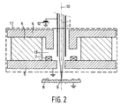
- Figure 2 shows an apparatus that is virtually identical to the apparatus according to figure 1a, with the difference that electrode 3 is omitted in Figure 2, and the function of this electrode 3 is assumed by pole piece 5, which is now electrically earthed.
- the magnetic pole piece 5 also acts as an electrode of the electrostatic lens, and the focusing electric field is formed by the voltage difference between electrode 2 and pole piece 5.
- the magnetic pole piece 5 is made of electrically conductive material and is connected to earth potential. Simulations conducted on the basis of this embodiment have shown that, in this manner, a geometry can be found whereby - as desired by the invention the focus position 9 can indeed be made independent of the landing energy.
Landscapes
- Chemical & Material Sciences (AREA)
- Analytical Chemistry (AREA)
- Electron Beam Exposure (AREA)
- Analysing Materials By The Use Of Radiation (AREA)
Abstract
The invention shows how it is possible to keep constant the focus position 9, independent of the energy of the particles in the beam 1, by combining a magnetic lens - that has been furnished with permanent-magnetic material - with an electrostatic lens. The electrostatic lens is embodied in that case as an accelerating lens.
Description
- a magnetic lens for producing a focusing magnetic field with the aid of magnetic pole pieces;
- an electrostatic lens for producing a focusing electric field, in which the beam undergoes an energy change,
Because the constitution of the sample can vary from location to location, it may be desirable to adjust the landing energy commensurate with this varying constitution. In that context, it is desirable that the focus position of the beam does not shift with respect to the focusing device. This is of particular importance in a production environment, such as during the inspection of wafers, where adjustment of the focusing would disadvantageously influence the production throughput.
The focusing
The electrostatic lens consists of two tube-
A
Between the
The
The additional magnetic field generated by
The focusing action of the focusing
Since the energy of the
Claims (4)
- A particle-optical apparatus provided with a focusing device (11) having an optical axis (10) for the purpose of focusing a beam (1) of electrically charged particles upon a focus position (9), which focusing device (11) comprises:whereby the focusing electric field (20) is placed upstream with respect to a region (23) situated between the focusing magnetic lens (21) and the focus position (9), characterized in thata magnetic lens for producing a focusing magnetic field (21) with the aid of magnetic pole pieces (4,5);an electrostatic lens for producing a focusing electric field (20), in which the beam (1) undergoes an energy change,the magnetic lens is provided with permanent-magnetic material (6) for generating the focusing magnetic field (21) required for the lens action, and;said energy change has the form of an energy increase.
- A particle-optical apparatus according to claim 1, whereby there is a region present around the optical axis (10) in which region both the focusing magnetic field (21) and the focusing electric field (20) are present.
- A particle-optical apparatus according to one of the preceding claims, whereby the sample-side pole piece (5) of the magnetic lens is made of electrically conductive material, and functions additionally as an electrode of the electrostatic lens.
- A particle-optical apparatus according to one of the preceding claims, provided with adjustment means for rendering adjustable the focus position (9) that is to be held constant by the apparatus during imaging.
Applications Claiming Priority (2)
| Application Number | Priority Date | Filing Date | Title |
|---|---|---|---|
| NL1023260A NL1023260C1 (en) | 2003-04-24 | 2003-04-24 | Particle-optical device with a permanent magnetic lens and an electrostatic lens. |
| NL1023260 | 2003-04-24 |
Publications (3)
| Publication Number | Publication Date |
|---|---|
| EP1471562A2 true EP1471562A2 (en) | 2004-10-27 |
| EP1471562A3 EP1471562A3 (en) | 2006-11-22 |
| EP1471562B1 EP1471562B1 (en) | 2010-06-30 |
Family
ID=32960321
Family Applications (1)
| Application Number | Title | Priority Date | Filing Date |
|---|---|---|---|
| EP04076144A Expired - Lifetime EP1471562B1 (en) | 2003-04-24 | 2004-04-13 | Particle-optical apparatus with a permanent-magnetic lens and an electrostatic lens |
Country Status (6)
| Country | Link |
|---|---|
| US (1) | US7067820B2 (en) |
| EP (1) | EP1471562B1 (en) |
| JP (1) | JP4676714B2 (en) |
| CN (1) | CN100529726C (en) |
| DE (1) | DE602004027861D1 (en) |
| NL (1) | NL1023260C1 (en) |
Cited By (4)
| Publication number | Priority date | Publication date | Assignee | Title |
|---|---|---|---|---|
| NL2010433A (en) * | 2008-12-23 | 2013-05-16 | Zeiss Carl Nts Gmbh | Particle optical device with magnet assembly. |
| GB2508707A (en) * | 2012-10-17 | 2014-06-11 | Rigaku Denki Co Ltd | X-ray generating tube comprising a permanent focusing magnet |
| US12500060B2 (en) | 2021-07-14 | 2025-12-16 | Ims Nanofabrication Gmbh | Electromagnetic lens |
| US12706270B2 (en) | 2022-07-15 | 2026-08-11 | Ims Nanofabrication Gmbh | Adjustable permanent magnetic lens having thermal control device |
Families Citing this family (25)
| Publication number | Priority date | Publication date | Assignee | Title |
|---|---|---|---|---|
| US6897443B2 (en) * | 2003-06-02 | 2005-05-24 | Harald Gross | Portable scanning electron microscope |
| NL1026006C2 (en) * | 2004-04-22 | 2005-10-25 | Fei Co | Particle-optical device provided with lenses with permanent magnetic material. |
| JP4552191B2 (en) * | 2005-01-11 | 2010-09-29 | 日立金属株式会社 | Magnetic circuit for magnetic lens |
| JP4751635B2 (en) * | 2005-04-13 | 2011-08-17 | 株式会社日立ハイテクノロジーズ | Magnetic field superposition type electron gun |
| JP4795847B2 (en) * | 2006-05-17 | 2011-10-19 | 株式会社日立ハイテクノロジーズ | Electron lens and charged particle beam apparatus using the same |
| CN101461026B (en) * | 2006-06-07 | 2012-01-18 | Fei公司 | Plain bearings for use with devices containing vacuum chambers |
| US9429631B2 (en) * | 2007-09-11 | 2016-08-30 | William Patrick Crabtree | Device and method for altering the path of radio waves to record the image information available in said waves |
| US20090067059A1 (en) * | 2007-09-11 | 2009-03-12 | William Patrick Crabtree | Device and method for altering the path of magnetic waves to record the activity thereof |
| JP5363480B2 (en) * | 2008-06-24 | 2013-12-11 | 株式会社アドバンテスト | Multi-column electron beam exposure apparatus and magnetic field generator |
| KR101318592B1 (en) * | 2009-11-26 | 2013-10-15 | 가부시키가이샤 히다치 하이테크놀로지즈 | Scanning electron microscope |
| JP5259688B2 (en) | 2010-12-09 | 2013-08-07 | 本田技研工業株式会社 | Scanning electron microscope |
| US8319181B2 (en) * | 2011-01-30 | 2012-11-27 | Fei Company | System and method for localization of large numbers of fluorescent markers in biological samples |
| US8455838B2 (en) * | 2011-06-29 | 2013-06-04 | Kla-Tencor Corporation | Multiple-column electron beam apparatus and methods |
| EP2706554B1 (en) | 2012-09-10 | 2016-05-25 | Fei Company | Method of using a compound particle-optical lens |
| US9165745B2 (en) * | 2013-03-10 | 2015-10-20 | Maglen Pte Ltd | Permanent magnet based high performance multi-axis immersion electron lens array with low axial leakage field |
| EP2827357A1 (en) | 2013-07-18 | 2015-01-21 | Fei Company | Magnetic lens for focusing a beam of charged particles |
| TWI502616B (en) * | 2014-08-08 | 2015-10-01 | 國立清華大學 | Desktop electron microscope and its wide-area adjustable magnetic lens |
| CN105307370A (en) * | 2015-11-19 | 2016-02-03 | 丹东华日理学电气股份有限公司 | Microfocus X-ray source device based on Ethernet control |
| US10410827B2 (en) | 2017-05-03 | 2019-09-10 | Fei Company | Gun lens design in a charged particle microscope |
| IL283084B2 (en) * | 2018-11-16 | 2026-01-01 | Asml Netherlands Bv | Electromagnetic compound lens and charged particle optical system with such a lens |
| EP4095882A1 (en) | 2021-05-25 | 2022-11-30 | IMS Nanofabrication GmbH | Pattern data processing for programmable direct-write apparatus |
| US12154756B2 (en) | 2021-08-12 | 2024-11-26 | Ims Nanofabrication Gmbh | Beam pattern device having beam absorber structure |
| JP2023138912A (en) | 2022-03-21 | 2023-10-03 | アイエムエス ナノファブリケーション ゲーエムベーハー | Compensation for thermal expansion in lithography techniques |
| JP2023166336A (en) | 2022-05-09 | 2023-11-21 | アイエムエス ナノファブリケーション ゲーエムベーハー | Adjustable Permanent Magnet Lens with Shunt Device |
| CN119673731B (en) * | 2025-02-11 | 2025-05-06 | 合肥国家实验室 | Stacked magnetic lens |
Family Cites Families (15)
| Publication number | Priority date | Publication date | Assignee | Title |
|---|---|---|---|---|
| GB2115976A (en) * | 1982-02-26 | 1983-09-14 | Philips Electronic Associated | Charged particle beam apparatus |
| JPS61101944A (en) * | 1984-10-25 | 1986-05-20 | Nippon Telegr & Teleph Corp <Ntt> | Charged particle beam focusing system |
| EP0242602B1 (en) * | 1986-04-24 | 1993-07-21 | ICT Integrated Circuit Testing Gesellschaft für Halbleiterprüftechnik mbH | Electrostatic and magnetic lens for corpuscular beam apparatus |
| DE3620727A1 (en) * | 1986-06-20 | 1987-12-23 | Pfisterer Elektrotech Karl | VIBRATION DAMPER FOR ELECTRICAL OVERHEAD LINES |
| GB2192092A (en) | 1986-06-25 | 1987-12-31 | Philips Electronic Associated | Magnetic lens system |
| US4815104A (en) * | 1988-01-11 | 1989-03-21 | Telect, Inc. | Digital telecommunications network, cross-connect module |
| JP2835265B2 (en) * | 1992-08-27 | 1998-12-14 | 株式会社東芝 | Magnetic field immersion type electron gun and method of operating magnetic field immersion type electron gun |
| KR970005769B1 (en) * | 1992-08-27 | 1997-04-19 | 가부시끼가이샤 도시바 | Magnetic field gun |
| JPH0864163A (en) * | 1994-08-19 | 1996-03-08 | Jeol Ltd | Charged particle beam device |
| US5780859A (en) * | 1996-02-16 | 1998-07-14 | Act Advanced Circuit Testing Gesellschaft | Electrostatic-magnetic lens arrangement |
| US6051839A (en) | 1996-06-07 | 2000-04-18 | Arch Development Corporation | Magnetic lens apparatus for use in high-resolution scanning electron microscopes and lithographic processes |
| JPH1128544A (en) * | 1997-07-03 | 1999-02-02 | Kanto Yakin Kogyo Kk | Method for manufacturing metal honeycomb structure |
| SG74599A1 (en) | 1997-09-27 | 2000-08-22 | Inst Of Material Res & Enginee | Portable high resolution scanning electron microscope column using permanent magnet electron lenses |
| JPH11283544A (en) | 1998-03-31 | 1999-10-15 | Advantest Corp | Electron beam irradiation device |
| US6392231B1 (en) * | 2000-02-25 | 2002-05-21 | Hermes-Microvision, Inc. | Swinging objective retarding immersion lens electron optics focusing, deflection and signal collection system and method |
-
2003
- 2003-04-24 NL NL1023260A patent/NL1023260C1/en not_active IP Right Cessation
-
2004
- 2004-04-13 EP EP04076144A patent/EP1471562B1/en not_active Expired - Lifetime
- 2004-04-13 DE DE602004027861T patent/DE602004027861D1/en not_active Expired - Lifetime
- 2004-04-20 JP JP2004124235A patent/JP4676714B2/en not_active Expired - Fee Related
- 2004-04-21 US US10/829,002 patent/US7067820B2/en not_active Expired - Lifetime
- 2004-04-23 CN CNB2004100434134A patent/CN100529726C/en not_active Expired - Lifetime
Cited By (6)
| Publication number | Priority date | Publication date | Assignee | Title |
|---|---|---|---|---|
| NL2010433A (en) * | 2008-12-23 | 2013-05-16 | Zeiss Carl Nts Gmbh | Particle optical device with magnet assembly. |
| GB2508707A (en) * | 2012-10-17 | 2014-06-11 | Rigaku Denki Co Ltd | X-ray generating tube comprising a permanent focusing magnet |
| US9159524B2 (en) | 2012-10-17 | 2015-10-13 | Rigaku Corporation | X-ray generating apparatus |
| GB2508707B (en) * | 2012-10-17 | 2017-07-19 | Rigaku Denki Co Ltd | X-ray generating apparatus |
| US12500060B2 (en) | 2021-07-14 | 2025-12-16 | Ims Nanofabrication Gmbh | Electromagnetic lens |
| US12706270B2 (en) | 2022-07-15 | 2026-08-11 | Ims Nanofabrication Gmbh | Adjustable permanent magnetic lens having thermal control device |
Also Published As
| Publication number | Publication date |
|---|---|
| EP1471562B1 (en) | 2010-06-30 |
| EP1471562A3 (en) | 2006-11-22 |
| DE602004027861D1 (en) | 2010-08-12 |
| CN1590979A (en) | 2005-03-09 |
| CN100529726C (en) | 2009-08-19 |
| US7067820B2 (en) | 2006-06-27 |
| US20040211914A1 (en) | 2004-10-28 |
| JP4676714B2 (en) | 2011-04-27 |
| JP2004327439A (en) | 2004-11-18 |
| NL1023260C1 (en) | 2004-10-27 |
Similar Documents
| Publication | Publication Date | Title |
|---|---|---|
| EP1471562B1 (en) | Particle-optical apparatus with a permanent-magnetic lens and an electrostatic lens | |
| US5146090A (en) | Particle beam apparatus having an immersion lens arranged in an intermediate image of the beam | |
| TWI435362B (en) | Charged particle apparatus | |
| KR102211668B1 (en) | Device of multiple charged particle beams | |
| CN102103966B (en) | Particle-optical component | |
| EP2128887B1 (en) | TEM with aberration corrector and phase plate | |
| US6218664B1 (en) | SEM provided with an electrostatic objective and an electrical scanning device | |
| US6825475B2 (en) | Deflection method and system for use in a charged particle beam column | |
| KR19990028770A (en) | Correction apparatus for correcting lens aberrations in particle-optical devices | |
| EP3594988B1 (en) | High performance inspection scanning electron microscope device and method of operating the same | |
| JP2017517119A (en) | Electron beam imaging using a double Wien filter monochromator | |
| EP1018757B1 (en) | Charged particle beam emitting device | |
| US20020109089A1 (en) | SEM provided with an adjustable final electrode in the electrostatic objective | |
| JP6138454B2 (en) | Charged particle beam equipment | |
| US9443693B2 (en) | Notched magnetic lens for improved sample access in an SEM | |
| US6555824B1 (en) | Method and device for focusing a charged particle beam | |
| JP6204388B2 (en) | Charged particle beam apparatus and scanning electron microscope | |
| US20260094783A1 (en) | Multiple particle beam system, in particular multi-beam particle microscope, having a fast magnetic lens and the use thereof |
Legal Events
| Date | Code | Title | Description |
|---|---|---|---|
| PUAI | Public reference made under article 153(3) epc to a published international application that has entered the european phase |
Free format text: ORIGINAL CODE: 0009012 |
|
| 17P | Request for examination filed |
Effective date: 20040413 |
|
| AK | Designated contracting states |
Kind code of ref document: A2 Designated state(s): AT BE BG CH CY CZ DE DK EE ES FI FR GB GR HU IE IT LI LU MC NL PL PT RO SE SI SK TR |
|
| AX | Request for extension of the european patent |
Extension state: AL HR LT LV MK |
|
| PUAL | Search report despatched |
Free format text: ORIGINAL CODE: 0009013 |
|
| AK | Designated contracting states |
Kind code of ref document: A3 Designated state(s): AT BE BG CH CY CZ DE DK EE ES FI FR GB GR HU IE IT LI LU MC NL PL PT RO SE SI SK TR |
|
| AX | Request for extension of the european patent |
Extension state: AL HR LT LV MK |
|
| RIC1 | Information provided on ipc code assigned before grant |
Ipc: H01J 37/26 20060101ALI20061017BHEP Ipc: H01J 37/145 20060101AFI20040804BHEP |
|
| AKX | Designation fees paid |
Designated state(s): DE FR GB |
|
| 17Q | First examination report despatched |
Effective date: 20080428 |
|
| GRAP | Despatch of communication of intention to grant a patent |
Free format text: ORIGINAL CODE: EPIDOSNIGR1 |
|
| GRAS | Grant fee paid |
Free format text: ORIGINAL CODE: EPIDOSNIGR3 |
|
| GRAA | (expected) grant |
Free format text: ORIGINAL CODE: 0009210 |
|
| AK | Designated contracting states |
Kind code of ref document: B1 Designated state(s): DE FR GB |
|
| REG | Reference to a national code |
Ref country code: GB Ref legal event code: FG4D |
|
| REF | Corresponds to: |
Ref document number: 602004027861 Country of ref document: DE Date of ref document: 20100812 Kind code of ref document: P |
|
| PLBE | No opposition filed within time limit |
Free format text: ORIGINAL CODE: 0009261 |
|
| STAA | Information on the status of an ep patent application or granted ep patent |
Free format text: STATUS: NO OPPOSITION FILED WITHIN TIME LIMIT |
|
| 26N | No opposition filed |
Effective date: 20110331 |
|
| REG | Reference to a national code |
Ref country code: DE Ref legal event code: R097 Ref document number: 602004027861 Country of ref document: DE Effective date: 20110330 |
|
| REG | Reference to a national code |
Ref country code: FR Ref legal event code: PLFP Year of fee payment: 13 |
|
| REG | Reference to a national code |
Ref country code: FR Ref legal event code: PLFP Year of fee payment: 14 |
|
| REG | Reference to a national code |
Ref country code: FR Ref legal event code: PLFP Year of fee payment: 15 |
|
| PGFP | Annual fee paid to national office [announced via postgrant information from national office to epo] |
Ref country code: FR Payment date: 20190313 Year of fee payment: 16 |
|
| PGFP | Annual fee paid to national office [announced via postgrant information from national office to epo] |
Ref country code: DE Payment date: 20190402 Year of fee payment: 16 |
|
| PGFP | Annual fee paid to national office [announced via postgrant information from national office to epo] |
Ref country code: GB Payment date: 20190410 Year of fee payment: 16 |
|
| REG | Reference to a national code |
Ref country code: DE Ref legal event code: R119 Ref document number: 602004027861 Country of ref document: DE |
|
| PG25 | Lapsed in a contracting state [announced via postgrant information from national office to epo] |
Ref country code: FR Free format text: LAPSE BECAUSE OF NON-PAYMENT OF DUE FEES Effective date: 20200430 Ref country code: DE Free format text: LAPSE BECAUSE OF NON-PAYMENT OF DUE FEES Effective date: 20201103 |
|
| GBPC | Gb: european patent ceased through non-payment of renewal fee |
Effective date: 20200413 |
|
| PG25 | Lapsed in a contracting state [announced via postgrant information from national office to epo] |
Ref country code: GB Free format text: LAPSE BECAUSE OF NON-PAYMENT OF DUE FEES Effective date: 20200413 |