EP1471367A1 - Radar - Google Patents
Radar Download PDFInfo
- Publication number
- EP1471367A1 EP1471367A1 EP02716408A EP02716408A EP1471367A1 EP 1471367 A1 EP1471367 A1 EP 1471367A1 EP 02716408 A EP02716408 A EP 02716408A EP 02716408 A EP02716408 A EP 02716408A EP 1471367 A1 EP1471367 A1 EP 1471367A1
- Authority
- EP
- European Patent Office
- Prior art keywords
- target
- radar
- antenna unit
- vehicle
- wave
- Prior art date
- Legal status (The legal status is an assumption and is not a legal conclusion. Google has not performed a legal analysis and makes no representation as to the accuracy of the status listed.)
- Withdrawn
Links
Images





Classifications
-
- G—PHYSICS
- G01—MEASURING; TESTING
- G01S—RADIO DIRECTION-FINDING; RADIO NAVIGATION; DETERMINING DISTANCE OR VELOCITY BY USE OF RADIO WAVES; LOCATING OR PRESENCE-DETECTING BY USE OF THE REFLECTION OR RERADIATION OF RADIO WAVES; ANALOGOUS ARRANGEMENTS USING OTHER WAVES
- G01S13/00—Systems using the reflection or reradiation of radio waves, e.g. radar systems; Analogous systems using reflection or reradiation of waves whose nature or wavelength is irrelevant or unspecified
- G01S13/88—Radar or analogous systems specially adapted for specific applications
- G01S13/93—Radar or analogous systems specially adapted for specific applications for anti-collision purposes
- G01S13/931—Radar or analogous systems specially adapted for specific applications for anti-collision purposes of land vehicles
-
- G—PHYSICS
- G01—MEASURING; TESTING
- G01S—RADIO DIRECTION-FINDING; RADIO NAVIGATION; DETERMINING DISTANCE OR VELOCITY BY USE OF RADIO WAVES; LOCATING OR PRESENCE-DETECTING BY USE OF THE REFLECTION OR RERADIATION OF RADIO WAVES; ANALOGOUS ARRANGEMENTS USING OTHER WAVES
- G01S13/00—Systems using the reflection or reradiation of radio waves, e.g. radar systems; Analogous systems using reflection or reradiation of waves whose nature or wavelength is irrelevant or unspecified
- G01S13/88—Radar or analogous systems specially adapted for specific applications
- G01S13/93—Radar or analogous systems specially adapted for specific applications for anti-collision purposes
- G01S13/931—Radar or analogous systems specially adapted for specific applications for anti-collision purposes of land vehicles
- G01S2013/93185—Controlling the brakes
-
- G—PHYSICS
- G01—MEASURING; TESTING
- G01S—RADIO DIRECTION-FINDING; RADIO NAVIGATION; DETERMINING DISTANCE OR VELOCITY BY USE OF RADIO WAVES; LOCATING OR PRESENCE-DETECTING BY USE OF THE REFLECTION OR RERADIATION OF RADIO WAVES; ANALOGOUS ARRANGEMENTS USING OTHER WAVES
- G01S13/00—Systems using the reflection or reradiation of radio waves, e.g. radar systems; Analogous systems using reflection or reradiation of waves whose nature or wavelength is irrelevant or unspecified
- G01S13/88—Radar or analogous systems specially adapted for specific applications
- G01S13/93—Radar or analogous systems specially adapted for specific applications for anti-collision purposes
- G01S13/931—Radar or analogous systems specially adapted for specific applications for anti-collision purposes of land vehicles
- G01S2013/932—Radar or analogous systems specially adapted for specific applications for anti-collision purposes of land vehicles using own vehicle data, e.g. ground speed, steering wheel direction
-
- G—PHYSICS
- G01—MEASURING; TESTING
- G01S—RADIO DIRECTION-FINDING; RADIO NAVIGATION; DETERMINING DISTANCE OR VELOCITY BY USE OF RADIO WAVES; LOCATING OR PRESENCE-DETECTING BY USE OF THE REFLECTION OR RERADIATION OF RADIO WAVES; ANALOGOUS ARRANGEMENTS USING OTHER WAVES
- G01S13/00—Systems using the reflection or reradiation of radio waves, e.g. radar systems; Analogous systems using reflection or reradiation of waves whose nature or wavelength is irrelevant or unspecified
- G01S13/88—Radar or analogous systems specially adapted for specific applications
- G01S13/93—Radar or analogous systems specially adapted for specific applications for anti-collision purposes
- G01S13/931—Radar or analogous systems specially adapted for specific applications for anti-collision purposes of land vehicles
- G01S2013/9325—Radar or analogous systems specially adapted for specific applications for anti-collision purposes of land vehicles for inter-vehicle distance regulation, e.g. navigating in platoons
-
- G—PHYSICS
- G01—MEASURING; TESTING
- G01S—RADIO DIRECTION-FINDING; RADIO NAVIGATION; DETERMINING DISTANCE OR VELOCITY BY USE OF RADIO WAVES; LOCATING OR PRESENCE-DETECTING BY USE OF THE REFLECTION OR RERADIATION OF RADIO WAVES; ANALOGOUS ARRANGEMENTS USING OTHER WAVES
- G01S13/00—Systems using the reflection or reradiation of radio waves, e.g. radar systems; Analogous systems using reflection or reradiation of waves whose nature or wavelength is irrelevant or unspecified
- G01S13/88—Radar or analogous systems specially adapted for specific applications
- G01S13/93—Radar or analogous systems specially adapted for specific applications for anti-collision purposes
- G01S13/931—Radar or analogous systems specially adapted for specific applications for anti-collision purposes of land vehicles
- G01S2013/9327—Sensor installation details
- G01S2013/93271—Sensor installation details in the front of the vehicles
Definitions
- the present invention relates to a radar for detecting the presence or the like of a target by transmitting a radio wave and receiving its reflected wave.
- Some radars mounted on vehicles can detect the azimuth angle of a target existing on a road (a deviation angle between a directional line from the radar to the target: hereinafter called a target azimuth angle).
- a target azimuth angle a deviation angle between a directional line from the radar to the target.
- a mechanical scan type radar which realizes horizontal scanning of a main beam of a transceiver antenna by mechanically swinging the transceiver antenna
- a beam switching type radar which realizes horizontal scanning of a main beam by sequentially switching between transceivers for transmitting beams having different directions
- a monopulse type radar which detects a target azimuth angle in the horizontal plane from a phase difference of reception waves received by two antennas disposed right and left.
- the radars mounted on vehicles enumerated herein all have as their main object detecting a target on a road, so that only the target azimuth angle in the horizontal plane is detected.
- An object of the present invention is to provide a radar capable of detecting a target azimuth angle in an arbitrary plane including a reference axis.
- a radar of this invention comprises: (1) an antenna unit for transmitting a radio wave and receiving a reflected wave of the radio wave; (2) rotating means for rotating the antenna unit about an axis along a direction of transmitting the radio wave; and (3) control means for detecting an azimuth of a target from the reflected wave, the azimuth using the axis as a reference and being defined in a plane determined from a posture of the antenna unit and the axis.
- a radar 100 has: a wave transmission unit 10 radiating a radio wave L toward an external; a wave reception unit 20 for receiving echoes La and Lb from targets (not shown) existing in the external; a control unit 30 for controlling the whole of the radar 100; a frame 40 accommodating these units 10, 20 and 30; a motor 50 for rotating the frame 40 about the central axis of the radio wave L (a boresight L 0 in Figs. 3 and 8), and other components.
- the central axis L 0 of the radio wave L is hereinafter used as the reference axis of the target azimuth.
- the wave transmission unit 10 has: a modulator 11 for alternately outputting two types of modulated signals in response to a switching command from the control unit 30; an oscillator 12 for outputting a high frequency signal (e.g., a radio wave signal in a millimeter wave band) having an oscillation frequency corresponding to the modulated signal from the modulator 11; a transmission antenna element 13 for transmitting an output from the oscillator 12 as the radio wave L; a directional coupler 14 for guiding a portion of an output of the oscillator 12 to the wave reception unit 20 as the reference signal for frequency conversion, and other components.
- a modulator 11 for alternately outputting two types of modulated signals in response to a switching command from the control unit 30
- an oscillator 12 for outputting a high frequency signal (e.g., a radio wave signal in a millimeter wave band) having an oscillation frequency corresponding to the modulated signal from the modulator 11
- a transmission antenna element 13 for transmitting an output from the oscillator 12 as the radio
- the wave reception unit 20 has: two reception antenna elements 21a and 21b juxtaposed with the transmission antenna element 13 in the state being directed along the radiation direction of the radio wave L; a signal coupler (hybrid circuit or the like) 22 for acquiring a sum signal and a different signal of outputs from the two reception antenna elements 21a and 21b, respectively for each of the oscillation frequencies f 1 and f 2 ; a first mixer 23a for mixing the sum signal from the signal coupler 22 and the signal from the directional coupler 14 to generate a beat signal, respectively for each of the oscillation frequencies f 1 and f 2 ; a second mixer 23b for mixing the difference signal from the signal coupler 22 and the signal from the directional coupler 14 to generate a beat signal (doppler signal), respectively for each of the oscillation frequencies f 1 and f 2 ; an analog circuit 24 for demodulating and amplifying the beat signals (doppler signals) from the mixers 23a and 23b, respectively for each of the oscillation signals f 1 and f
- the wave reception unit 20 receives echoes from the targets at different positions, and detects the echoes La and Lb received at the different positions, separately for each of the oscillation frequencies f 1 and f 2 .
- the sampled signals of the doppler signals generated from the sun and difference signals as the detection results are input to the next control unit 30, separately for each of the oscillation frequencies f 1 and f 2 .
- the control unit 30 has: a motor control circuit 32 for controlling the rotation angle of the motor 50; a microcomputer 31 for analyzing the detection results of the wave reception unit 20 to generate a command to be supplied to the motor control circuit 32 or an external apparatus (an alarm apparatus or the like); and other components.
- the microcomputer 31 realizes an FFT (FFT: Fast Fourier Transform) unit 31A and a signal processing unit 31B by executing software.
- the FFT unit 31A detects, from the detection results of the wave reception unit 20, information necessary for calculating target information (a distance between the radar and each target, a relative velocity of the radar 100 and each target, and a target azimuth angle in the plane including the centers of the two reception antenna elements 21a and 21b and the reference axis).
- the signal processing unit 31B instructs a switching timing of the two oscillation frequencies f 1 and f 2 to the modulator 11 and analog circuit 24 and supplies a control command corresponding to the detection results by the FFT unit 31A to the motor control circuit 32 or external apparatus.
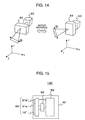
- the array direction of the antenna elements 13, 21a and 21b can be changed from an X-direction to a Y-direction and from the Y-direction to the X-direction, for example, in accordance with the state and the like of the radar 100 in its cover area.
- the radar 100 of the monopulse type for detecting essentially only the target azimuth in the horizontal plane (XZ plane) can change the azimuth direction ⁇ in its angle cover area from the X-direction to the Y-direction and from the Y-direction to the X-direction.
- the signal processing unit 31B is made to control the rotation angle of the motor 50 more finely, the array of the antenna elements 13, 21a and 21b can be made to acquire an arbitrary posture in the YX plane, so that it is possible to detect the target azimuth angle in an arbitrary plane including the reference axis.
- the shaft of the motor 50 is fixed to the frame 40 accommodating therein the control unit 30, wave transmission unit 10 and wave reception unit 20, this configuration is not necessarily required if rotation of the shaft of the motor 50 can be transmitted to the frame 40.
- rotation of the shaft of the motor 50 may be transmitted to the frame 40 via a transmission belt or the like.
- a mechanism different from the motor may be used if the frame 40 is provided with a rotation motion about the reference axis.
- the frame held by a rotary shaft may be swung by a magnet or the like.
- the frame 40 accommodating therein the control unit 30, wave transmission unit 10 and wave reception unit 20 is rotated as a whole, this configuration is not necessarily required.
- the shaft of the motor 50 may be fixed to an antenna array 60 having an antenna element 13' functioning as the transmission antenna element 13 of the wave transmission unit 20 and antenna elements 21a' and 21b' functioning as the two antenna elements 21 of the wave reception unit 20 to rotate only the antenna array 60.
- the motor 50 can also be accommodated in the frame 40.
- the description will be made on the processes to be executed by the microcomputer 31, i.e., the processes to be executed by the above-described functional structures 31A and 31B realized by software.
- the description will be made by taking as an example the case wherein the radar 100 is mounted on the front of a vehicle 200 in such a manner that the running direction of the vehicle 200 is generally parallel to the reference axis L 0 , and an ACC (Adaptive Cruise Control) system 202 and an alarm apparatus 201 of the vehicle are connected to the radar 100 as the above-described external apparatus.
- ACC Adaptive Cruise Control
- Fig. 4 is a flow chart illustrating the processes to be executed by the microcomputer 31 of the radar 100.
- the signal processing unit 31B starts instructing a switching timing of two oscillation frequencies f 1 and f 2 (Step400). Therefore, the switching timings of the two oscillation frequencies f 1 and f 2 are alternately and periodically supplied to the modulator 11 of the wave transmission unit 10 and the analog circuit 24 of the wave reception unit 20.
- the wave transmission unit 10 oscillates thereafter alternately and periodically the continuous waves F 1 and F 2 having the oscillation frequencies f 1 and f 2 , whereas the wave reception unit 20 can detect an echo from each target, respectively for each of the oscillation frequencies f 1 and f 2 , on the assumption that each target exists in the radiation area of the radio wave L.
- the FFT unit 31A dissolves the sampled signals supplied from the reception unit 20 into frequency components through fast Fourier transform (FFT: Fast Fourier Transform), respectively for each of the oscillation frequencies. Therefore, as shown in Fig. 6, a frequency spectrum 500 having peak signals corresponding to the targets (as an example of this case, two peak signals 500A and 500B) can be obtained for each oscillation frequency and for each of the doppler signals obtained from the sum signal and difference signal of the reception signals by the two reception antenna elements 21a and 21b.
- the FFT unit 31A detects the peak signals of each frequency spectrum through a threshold value process, and outputs the frequency and phase of each peak signal to the signal processing unit 31B (Step401).
- the phase of the peak signal of each frequency spectrum is given as an angle between the peak and the real value axis of each frequency spectrum represented by a complex number.
- the signal processing unit 31B calculates, as shown in the following, the target information of each target (a distance to the target from the radar 100, a relative velocity of the radar 100 and target, a target azimuth angle in the horizontal plane) (Step402).
- the doppler signals generated from the sum signal or difference signal of the reception signals by the two reception antenna elements 21a and 21b, respectively for each of the oscillation frequencies f 1 and f 2 have a phase difference proportional to the distance between the radar 100 and target, as shown in Fig. 7, and the doppler frequency of the doppler signals is proportional to the relative velocity of the radar 100 and target. It is therefore assumed herein that the signal processing unit 31B calculates the distance D to the target and the relative velocity V of the target in accordance with the frequency and phase of the peak signal in the frequency spectra of two doppler signals obtained from the sum signal for each of the two oscillation frequencies. Specifically, the following two equations (1) and (2) are used.
- c is a light velocity
- ⁇ is a phase difference ⁇ 1 - ⁇ 2 ) between the peak signals ⁇ 1 and ⁇ 2 of the frequency spectrum of each doppler signal obtained from the sum signal of the reception signals by the two reception antenna elements 21a and 21b for each of the two oscillation frequencies f 1 and f 2
- ⁇ f is a difference (f 1 - f 2 ) between the two oscillation frequencies f 1 and f 2
- fd is an average (fd 1 + fd 2 )/2 of the frequencies (doppler frequencies) fd 1 and fd 2 of the peak signals of each frequency spectrum obtained from the sum signal of the reception signals by the two reception antenna elements 21a and 21b for each of the two oscillation frequencies f 1 and f 2
- fc is an average (f 1 + f 2 )/2 of the oscillation frequencies f 1 and f 2
- an amplitude ratio (difference signal / sum signal) of the difference signal to the sum signal of the reception signals by the two reception antenna elements 21a and 21b is a target azimuth angle in the plane including the centers of the two reception antenna elements 21, 21 and the reference axis L 0 , i.e., a value representative of the target azimuth angle ⁇ in the horizontal plane.
- the signal processing unit 31B calculates, as the target azimuth angle ⁇ in the horizontal plane, the amplitude ratio (difference signal / sum signal) of peaks of the frequency spectra obtained from the beat signal of the sum signal corresponding to one frequency f 1 and the beat signal of the difference signal corresponding to the same frequency f 1 , among the outputs from the FFT unit 31A.
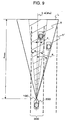
- the signal processing unit 31B defines a range which is supposed to be the area on the traffic lane 300 of the vehicle 200 in the horizontal plane, and judges whether this range contains the direction of the target azimuth angle contained in the target information of each target. Namely, the signal processing unit 31B judges whether each target exists on the traffic lane 300 of the vehicle 200 (Step403). For example, as shown in Fig.
- a local search range ⁇ having a predetermined width (e.g., about the width of the lane) at the longest search distance Rmax is defined so that the reference axis L 0 of the radar 100 becomes coincident with the center axis ⁇ 0 , and it is judged whether this local search range ⁇ contains the target azimuth angles ⁇ 1 and ⁇ 2 of the targets T 1 and T 2 . Therefore, in the traffic conditions shown in Fig. 9, one target T 1 is judged that it exists on the traffic lane 300 of the vehicle 200, whereas the other target T 2 does not exist on the traffic lane 300 of the vehicle 200. Further, as shown in Fig.
- the center axis ⁇ 0 of the local search range ⁇ defined when the traffic lane is generally straight is rotated by an angle ⁇ corresponding to the radius R of curvature of the traffic lane 300 (e.g., an angle given by a product of the radius R of curvature and an appropriate constant) toward the center O of the radius of curvature of the traffic lane 300, and it is judged whether this local search range ⁇ after rotation contains the target azimuth angles ⁇ 1 and ⁇ 2 of the targets T 1 and T 2 . Therefore, in the traffic conditions shown in Fig. 10, one target T 1 is judged that it exists on the traffic lane 300 of the vehicle 200, whereas the other target T 2 does not exist on the traffic lane 300 of the vehicle 200.
- the peak 500A contained in the determined frequency band 501 is generated by the echo from a standstill target (hereinafter called the stationary target), and the peak contained in the other frequency band is generated by the echo from a moving target (hereinafter called the moving target). Therefore, the process (at Step404) judges whether the stationary target exists on the traffic lane of the vehicles 200.
- the signal processing unit 31B supplies the alarm apparatus with a command for instructing to output a message containing the target information of each target, and supplies the target information of each target to the ACC system as a feedback signal (Step405).
- the alarm apparatus outputs the message containing the target information of the moving target, whereas the ACC system controls the drive system of the vehicle 200 so as to maintain some distance to the moving target.
- the microcomputer 31 executes the following process.
- the signal processing unit 31B supplies the motor control circuit 32 with a control command containing a rotation angle of "+ 90 degrees" of the motor 50.
- the motor control circuit 32 rotates the shaft of the motor 50 by + 90 degrees to rotate the frame 40 by + 90 degrees about the reference axis L 0 .
- the three antenna elements 13, 21a and 21b are therefore disposed in line generally along the vertical direction (Step406).
- the FFT unit 31A dissolves a new sampled signal from the wave reception unit 10 into frequency components and outputs the information necessary for calculating the target information of each target to the signal processing unit 31B, by the process similar to that at Step401 (Step407).
- the signal processing unit 31B further detects a stationary target from an output of the FFT unit 31A, by the process similar to that at Step404, and calculates the target azimuth angle in the vertical plane and the distance from the radar 100 respectively of the stationary target, by the process similar to that at Step402 (Step408). In accordance with the calculation results, the signal processing unit 31B calculates a height of the stationary target relative to the reference axis L 0 .
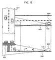
- the radar 100 calculates a product of the distance from the radar 100 to the stationary target and a sine value of the target azimuth angle in the vertical plane. For example, as shown in Fig. 12, if a high level road 301 three-dimensionally crossing the traffic lane 300 of the vehicle 200 is detected as the stationary target on the traffic lane 300 of the vehicle 200, the height h of the high level load 301 relative to the reference axis L 0 is calculated as a product D ⁇ sin ⁇ of the distance D from the high level road 301 to the radar 100 and the sine value sin ⁇ of the target azimuth ⁇ of the high level road 301 (Step409).
- the signal processing unit 31B judges whether the calculated height is larger than a predetermined threshold value h 0 (Step410).
- the threshold value to be compared is set to a value larger by a proper value than the height of the vehicle 200, i.e., to a lowest height allowing the vehicle 200 to pass through it safely. Therefore, this process judges whether the vehicle 200 can pass through the stationary target safely.
- the signal processing unit 31B supplies the motor control circuit 32 with a control command including the rotation angle "- 90 degrees" of the motor 50.
- the motor control circuit 32 rotates the shaft of the motor 50 by - 90 degrees to rotate the frame by - 90 degrees about the reference axis.
- the three antenna elements 13, 21a and 21b recover the initial condition that the elements are disposed in line generally along the horizontal direction (Step411). Thereafter, the microcomputer 31 returns to the process at Step401.
- the signal processing unit 31B supplies the alarm apparatus with an alarm command instructing to output an alarm message, and supplies the ACC system with an alarm command instructing deceleration (Step412). Therefore, the alarm apparatus outputs the alarm message to the effect that an obstacle exists ahead, whereas the ACC system controls the drive system of the vehicle 200 in order to apply a braking power to the vehicle 200. For example, as shown in Fig.
- the alarm apparatus outputs the alarm message to the effect that an obstacle exists ahead and the vehicle 200 is automatically decelerated.
- the alarm apparatus outputs the alarm message to the effect that an obstacle exists ahead, flushing an LED, outputting an alarm sound or the like may be used as an alarm reporting an occurrence of a predetermined trouble.
- the signal processing unit 31B supplies the motor control circuit 32 with the control command including the rotation angle "- 90 degrees" of the motor 50, similar to the case of judging that the vehicle 200 can pass through the stationary target safely, to thereby dispose the three antenna elements 13, 21a and 21b in line generally along the horizontal direction (Step411). Thereafter, the microcomputer 31 returns to the process at Step401.
- the height of the stationary target can be detected by rotating the angle cover area of the radar, so that it is possible to confirm whether the vehicle can pass through the stationary target on the traffic lane of the vehicle 200 safely. Since this confirmation result can be used for the judgment of necessity of an alarm message and for the control of a drive system of the vehicle, it is possible to prevent the vehicle 200 from being decelerated or an unnecessary alarm message from being output, in the case wherein a high level road or the like having no possibility of contact exists.
- the radar 100 may obviously be mounted not only on the vehicle 200 but also on other moving bodies.
- the alarm apparatus and ACC system are connected to the radar 100, this arrangement is not necessarily required.
- only one of the alarm apparatus and ACC system may be connected as an external apparatus to the radar 100, or another apparatus using an output (target information) of the radar 100 may be connected as an external apparatus to the radar 100.
- the alarm apparatus is mounted in the frame and connected to the microcomputer, the alarm apparatus is not necessary to be connected as an external apparatus to the radar 100.
- the radar to which the present invention is applicable is not limited to the two-frequency CW radar of the monopulse type.
- the present invention is applicable to radars of an azimuth detection type (mechanical scan type, a beam switching type and the like) different from the monopulse type, and radars of a modulation type (pulse radars, FM-CW radars and the like) different from the two-frequency CW type. Namely, even radars of any type can detect the target azimuth angle in an arbitrary plane including the reference axis by mounting a motor for rotating the azimuth angle in the cover area about the reference axis.
- a radar which can detect an azimuth angle of a target in an arbitrary plane including a reference azimuth.
Landscapes
- Engineering & Computer Science (AREA)
- Radar, Positioning & Navigation (AREA)
- Remote Sensing (AREA)
- Physics & Mathematics (AREA)
- Electromagnetism (AREA)
- Computer Networks & Wireless Communication (AREA)
- General Physics & Mathematics (AREA)
- Radar Systems Or Details Thereof (AREA)
Abstract
A radar of the present invention has: (1) an
antenna unit for transmitting a radio wave and
receiving a reflected wave of the radio wave; (2)
rotating means for rotating the antenna unit about an axis along a direction of transmitting the radio wave; and (3) control means for detecting an azimuth of a target from the reflected wave, the azimuth using the axis as a reference and being defined in a plane determined from a posture of the antenna unit and the axis.
rotating means for rotating the antenna unit about an axis along a direction of transmitting the radio wave; and (3) control means for detecting an azimuth of a target from the reflected wave, the azimuth using the axis as a reference and being defined in a plane determined from a posture of the antenna unit and the axis.
Description
The present invention relates to a radar for
detecting the presence or the like of a target by
transmitting a radio wave and receiving its reflected
wave.
Some radars mounted on vehicles can detect
the azimuth angle of a target existing on a road (a
deviation angle between a directional line from the
radar to the target: hereinafter called a target
azimuth angle). For example, "Development Trend of
Vehicle Millimeter Wave Radars", Journal of The
Institute of Electronics, Information and Communication
Engineers, Vol. 1996, October (pp. 977 - pp. 981)
describes: (1) a mechanical scan type radar which
realizes horizontal scanning of a main beam of a
transceiver antenna by mechanically swinging the
transceiver antenna; (2) a beam switching type radar
which realizes horizontal scanning of a main beam by
sequentially switching between transceivers for
transmitting beams having different directions; and (3)
a monopulse type radar which detects a target azimuth
angle in the horizontal plane from a phase difference
of reception waves received by two antennas disposed
right and left. The radars mounted on vehicles
enumerated herein all have as their main object
detecting a target on a road, so that only the target
azimuth angle in the horizontal plane is detected.
An object of the present invention is to
provide a radar capable of detecting a target azimuth
angle in an arbitrary plane including a reference axis.
In order to achieve this object, a radar of this
invention comprises: (1) an antenna unit for transmitting
a radio wave and receiving a reflected wave of the
radio wave; (2)
rotating means for rotating the antenna unit about an axis along a direction of transmitting the radio wave; and (3) control means for detecting an azimuth of a target from the reflected wave, the azimuth using the axis as a reference and being defined in a plane determined from a posture of the antenna unit and the axis.
rotating means for rotating the antenna unit about an axis along a direction of transmitting the radio wave; and (3) control means for detecting an azimuth of a target from the reflected wave, the azimuth using the axis as a reference and being defined in a plane determined from a posture of the antenna unit and the axis.
Specific constituent elements described in
the best mode for carrying out the invention are
intended to have the degree of freedom of as many
combinations as possible and each of the combinations
constitutes the present invention. For example, a mode
properly deleting some of the structure of the best
mode for carrying out the invention also constitutes an
embodiment of the invention.
With reference to the accompanying drawings,
description will be made in the following on the best
mode for carrying out the invention.
First, description will be made on the
structure of a two-frequency CW radar of a monopulse
type according to a preferred embodiment of the present
invention. Although a radar of a homodyne detection
type is used herein as an example, the invention is
also applicable to a radar of a heterodyne detection
type.
As shown in Fig. 1, a radar 100 according to
the preferred embodiment of the present invention has:
a wave transmission unit 10 radiating a radio wave L
toward an external; a wave reception unit 20 for
receiving echoes La and Lb from targets (not shown)
existing in the external; a control unit 30 for
controlling the whole of the radar 100; a frame 40
accommodating these units 10, 20 and 30; a motor 50 for
rotating the frame 40 about the central axis of the
radio wave L (a boresight L0 in Figs. 3 and 8), and
other components. The central axis L0 of the radio wave
L is hereinafter used as the reference axis of the
target azimuth.
The wave transmission unit 10 has: a
modulator 11 for alternately outputting two types of
modulated signals in response to a switching command
from the control unit 30; an oscillator 12 for
outputting a high frequency signal (e.g., a radio wave
signal in a millimeter wave band) having an oscillation
frequency corresponding to the modulated signal from
the modulator 11; a transmission antenna element 13 for
transmitting an output from the oscillator 12 as the
radio wave L; a directional coupler 14 for guiding a
portion of an output of the oscillator 12 to the wave
reception unit 20 as the reference signal for frequency
conversion, and other components. With this
arrangement, two continuous waves F1 (oscillation
frequency f1) and F2 (oscillation frequency f2) having
different oscillation frequencies such as shown in Fig.
2 are alternately radiated from the transmission
antenna element 13 of the wave transmission unit 10.
The wave reception unit 20 has: two reception
antenna elements 21a and 21b juxtaposed with the
transmission antenna element 13 in the state being
directed along the radiation direction of the radio
wave L; a signal coupler (hybrid circuit or the like)
22 for acquiring a sum signal and a different signal of
outputs from the two reception antenna elements 21a and
21b, respectively for each of the oscillation
frequencies f1 and f2; a first mixer 23a for mixing the
sum signal from the signal coupler 22 and the signal
from the directional coupler 14 to generate a beat
signal, respectively for each of the oscillation
frequencies f1 and f2; a second mixer 23b for mixing the
difference signal from the signal coupler 22 and the
signal from the directional coupler 14 to generate a
beat signal (doppler signal), respectively for each of
the oscillation frequencies f1 and f2; an analog circuit
24 for demodulating and amplifying the beat signals
(doppler signals) from the mixers 23a and 23b,
respectively for each of the oscillation signals f1 and
f2, an A/D converter 25 for sampling an analog signal
output from the analog circuit 24 at predetermined
sampling intervals T [sec], separately for each of the
oscillation frequencies f1 and f2, and other components.
With this arrangement, the wave reception unit 20
receives echoes from the targets at different
positions, and detects the echoes La and Lb received at
the different positions, separately for each of the
oscillation frequencies f1 and f2. The sampled signals
of the doppler signals generated from the sun and
difference signals as the detection results are input
to the next control unit 30, separately for each of the
oscillation frequencies f1 and f2.
The control unit 30 has: a motor control
circuit 32 for controlling the rotation angle of the
motor 50; a microcomputer 31 for analyzing the
detection results of the wave reception unit 20 to
generate a command to be supplied to the motor control
circuit 32 or an external apparatus (an alarm apparatus
or the like); and other components. The microcomputer
31 realizes an FFT (FFT: Fast Fourier Transform) unit
31A and a signal processing unit 31B by executing
software. The FFT unit 31A detects, from the detection
results of the wave reception unit 20, information
necessary for calculating target information (a
distance between the radar and each target, a relative
velocity of the radar 100 and each target, and a target
azimuth angle in the plane including the centers of the
two reception antenna elements 21a and 21b and the
reference axis). The signal processing unit 31B
instructs a switching timing of the two oscillation
frequencies f1 and f2 to the modulator 11 and analog
circuit 24 and supplies a control command corresponding
to the detection results by the FFT unit 31A to the
motor control circuit 32 or external apparatus.
With this arrangement, as shown in Fig. 14,
since the frame 40 accommodating therein a serial array
of the antenna elements 13, 21a and 21b can be rotated
by the motor 50, the array direction of the antenna
elements 13, 21a and 21b can be changed from an X-direction
to a Y-direction and from the Y-direction to
the X-direction, for example, in accordance with the
state and the like of the radar 100 in its cover area.
Namely, even the radar 100 of the monopulse type for
detecting essentially only the target azimuth in the
horizontal plane (XZ plane) can change the azimuth
direction Θ in its angle cover area from the X-direction
to the Y-direction and from the Y-direction
to the X-direction. It is therefore possible to detect
not only the target azimuth angle in the horizontal
plane (XZ plane) but also the target azimuth angle in
the vertical plane (YZ plane). If the signal
processing unit 31B is made to control the rotation
angle of the motor 50 more finely, the array of the
antenna elements 13, 21a and 21b can be made to acquire
an arbitrary posture in the YX plane, so that it is
possible to detect the target azimuth angle in an
arbitrary plane including the reference axis.
In this embodiment, although the shaft of the
motor 50 is fixed to the frame 40 accommodating therein
the control unit 30, wave transmission unit 10 and wave
reception unit 20, this configuration is not
necessarily required if rotation of the shaft of the
motor 50 can be transmitted to the frame 40. For
example, rotation of the shaft of the motor 50 may be
transmitted to the frame 40 via a transmission belt or
the like. A mechanism different from the motor may be
used if the frame 40 is provided with a rotation motion
about the reference axis. For example, the frame held
by a rotary shaft may be swung by a magnet or the like.
Further, in this embodiment, although the
frame 40 accommodating therein the control unit 30,
wave transmission unit 10 and wave reception unit 20 is
rotated as a whole, this configuration is not
necessarily required. For example, as shown in Fig.
15, the shaft of the motor 50 may be fixed to an
antenna array 60 having an antenna element 13'
functioning as the transmission antenna element 13 of
the wave transmission unit 20 and antenna elements 21a'
and 21b' functioning as the two antenna elements 21 of
the wave reception unit 20 to rotate only the antenna
array 60. In this case, the motor 50 can also be
accommodated in the frame 40.
Next, description will be made on the
processes to be executed by the microcomputer 31, i.e.,
the processes to be executed by the above-described
functional structures 31A and 31B realized by software.
However, as shown in Fig. 3, the description will be
made by taking as an example the case wherein the radar
100 is mounted on the front of a vehicle 200 in such a
manner that the running direction of the vehicle 200 is
generally parallel to the reference axis L0, and an ACC
(Adaptive Cruise Control) system 202 and an alarm
apparatus 201 of the vehicle are connected to the radar
100 as the above-described external apparatus.
Fig. 4 is a flow chart illustrating the
processes to be executed by the microcomputer 31 of the
radar 100.
First, as shown in Fig. 5, under the
conditions that the three antenna elements 13, 21a and
21b are disposed in line generally in the horizontal
direction, the signal processing unit 31B starts
instructing a switching timing of two oscillation
frequencies f1 and f2 (Step400). Therefore, the
switching timings of the two oscillation frequencies f1
and f2 are alternately and periodically supplied to the
modulator 11 of the wave transmission unit 10 and the
analog circuit 24 of the wave reception unit 20.
Therefore, the wave transmission unit 10 oscillates
thereafter alternately and periodically the continuous
waves F1 and F2 having the oscillation frequencies f1 and
f2, whereas the wave reception unit 20 can detect an
echo from each target, respectively for each of the
oscillation frequencies f1 and f2, on the assumption
that each target exists in the radiation area of the
radio wave L.
As the wave reception unit 20 starts
detecting an echo from each target, the FFT unit 31A
dissolves the sampled signals supplied from the
reception unit 20 into frequency components through
fast Fourier transform (FFT: Fast Fourier Transform),
respectively for each of the oscillation frequencies.
Therefore, as shown in Fig. 6, a frequency spectrum 500
having peak signals corresponding to the targets (as an
example of this case, two peak signals 500A and 500B)
can be obtained for each oscillation frequency and for
each of the doppler signals obtained from the sum
signal and difference signal of the reception signals
by the two reception antenna elements 21a and 21b. The
FFT unit 31A detects the peak signals of each frequency
spectrum through a threshold value process, and outputs
the frequency and phase of each peak signal to the
signal processing unit 31B (Step401). The phase of the
peak signal of each frequency spectrum is given as an
angle between the peak and the real value axis of each
frequency spectrum represented by a complex number.
Thereafter, in accordance with the outputs
from the FFT unit 31A, the signal processing unit 31B
calculates, as shown in the following, the target
information of each target (a distance to the target
from the radar 100, a relative velocity of the radar
100 and target, a target azimuth angle in the
horizontal plane) (Step402).
The doppler signals generated from the sum
signal or difference signal of the reception signals by
the two reception antenna elements 21a and 21b,
respectively for each of the oscillation frequencies f1
and f2 have a phase difference proportional to the
distance between the radar 100 and target, as shown in
Fig. 7, and the doppler frequency of the doppler
signals is proportional to the relative velocity of the
radar 100 and target. It is therefore assumed herein
that the signal processing unit 31B calculates the
distance D to the target and the relative velocity V of
the target in accordance with the frequency and phase
of the peak signal in the frequency spectra of two
doppler signals obtained from the sum signal for each
of the two oscillation frequencies. Specifically, the
following two equations (1) and (2) are used.
D = c·Δϕ /{4·π·Δf}
V = c·fd/(2·fc)
where: c is a light velocity; Δϕ is a phase difference
ϕ1 - ϕ2) between the peak signals ϕ1 and ϕ2 of the
frequency spectrum of each doppler signal obtained from
the sum signal of the reception signals by the two
reception antenna elements 21a and 21b for each of the
two oscillation frequencies f1 and f2; Δf is a
difference (f1 - f2) between the two oscillation
frequencies f1 and f2, fd is an average (fd1 + fd2)/2 of
the frequencies (doppler frequencies) fd1 and fd2 of the
peak signals of each frequency spectrum obtained from
the sum signal of the reception signals by the two
reception antenna elements 21a and 21b for each of the
two oscillation frequencies f1 and f2; and fc is an
average (f1 + f2)/2 of the oscillation frequencies f1 and
f2 (the same is applicable in the following).
As shown in Fig. 8, if the azimuth angle of
the target is not 0, the echoes La and Lb received by
the two reception antenna elements 21a and 21b have a
phase difference due to a difference δ between
propagation distances. Therefore, an amplitude ratio
(difference signal / sum signal) of the difference
signal to the sum signal of the reception signals by
the two reception antenna elements 21a and 21b is a
target azimuth angle in the plane including the centers
of the two reception antenna elements 21, 21 and the
reference axis L0, i.e., a value representative of the
target azimuth angle in the horizontal plane.
Therefore, the signal processing unit 31B calculates,
as the target azimuth angle in the horizontal plane,
the amplitude ratio (difference signal / sum signal) of
peaks of the frequency spectra obtained from the beat
signal of the sum signal corresponding to one frequency
f1 and the beat signal of the difference signal
corresponding to the same frequency f1, among the
outputs from the FFT unit 31A.
After the information of each target is
acquired in the above manner, the signal processing
unit 31B estimates the radius R of curvature of a
traffic lane of the vehicle 200 from the outputs of an
angular velocity sensor and a vehicle velocity sensor
mounted on the vehicle 200. Specifically, the radius R
of curvature of the traffic lane of the vehicle is
calculated by inputting an angular velocity ω and a
vehicle velocity v of the vehicle 200 and using a
function of 1/R = f(ω, v) outputting the radius R of
curvature of the traffic lane of the vehicle 200. In
accordance with the calculated radius R of curvature,
the signal processing unit 31B defines a range which is
supposed to be the area on the traffic lane 300 of the
vehicle 200 in the horizontal plane, and judges whether
this range contains the direction of the target azimuth
angle contained in the target information of each
target. Namely, the signal processing unit 31B judges
whether each target exists on the traffic lane 300 of
the vehicle 200 (Step403). For example, as shown in
Fig. 9, if the traffic lane 300 of the vehicle 200 is
generally straight, a local search range α having a
predetermined width (e.g., about the width of the lane)
at the longest search distance Rmax is defined so that
the reference axis L0 of the radar 100 becomes
coincident with the center axis α0, and it is judged
whether this local search range α contains the target
azimuth angles 1 and 2 of the targets T1 and T2.
Therefore, in the traffic conditions shown in Fig. 9,
one target T1 is judged that it exists on the traffic
lane 300 of the vehicle 200, whereas the other target T2
does not exist on the traffic lane 300 of the vehicle
200. Further, as shown in Fig. 10, if the traffic lane
300 of the vehicle 200 is curved, the center axis α0 of
the local search range α defined when the traffic lane
is generally straight is rotated by an angle β
corresponding to the radius R of curvature of the
traffic lane 300 (e.g., an angle given by a product of
the radius R of curvature and an appropriate constant)
toward the center O of the radius of curvature of the
traffic lane 300, and it is judged whether this local
search range α after rotation contains the target
azimuth angles 1 and 2 of the targets T1 and T2.
Therefore, in the traffic conditions shown in Fig. 10,
one target T1 is judged that it exists on the traffic
lane 300 of the vehicle 200, whereas the other target T2
does not exist on the traffic lane 300 of the vehicle
200.
If the judgement process (Step403) of this
kind shows that the target does not exist on the
traffic lane 300 of the vehicle 200, the microcomputer
31 returns to the process at S401. Conversely, if it
is judged that one or more targets exist on the traffic
lane 300 of the vehicle 200, as shown in Fig. 6 the
signal processing unit 31B determines a frequency band
501 having a predetermined width including a reference
frequency signal f0 (= 2·fc·v/c) generated through
frequency conversion of the vehicle velocity v supplied
from the vehicle velocity sensor, (the predetermined
width being, for example, a width of about 3% to 20% of
the reference frequency f0 on both sides of the
reference frequency), and judges whether a peak signal
exists in the frequency band 501 (Step404). The peak
500A contained in the determined frequency band 501 is
generated by the echo from a standstill target
(hereinafter called the stationary target), and the
peak contained in the other frequency band is generated
by the echo from a moving target (hereinafter called
the moving target). Therefore, the process (at
Step404) judges whether the stationary target exists on
the traffic lane of the vehicles 200.
If it is judged that a stationary target does
not exist on the traffic lane of the vehicle 200, i.e.,
if it is judged only a moving target exists on the
traffic lane of the vehicle 200, the signal processing
unit 31B supplies the alarm apparatus with a command
for instructing to output a message containing the
target information of each target, and supplies the
target information of each target to the ACC system as
a feedback signal (Step405). In this manner, the alarm
apparatus outputs the message containing the target
information of the moving target, whereas the ACC
system controls the drive system of the vehicle 200 so
as to maintain some distance to the moving target.
On the other hand, if it is judged that a
stationary target exists on the traffic lane of the
vehicle 200, the microcomputer 31 executes the
following process.
First, the signal processing unit 31B
supplies the motor control circuit 32 with a control
command containing a rotation angle of "+ 90 degrees"
of the motor 50. In response to this, as shown in Fig.
11, the motor control circuit 32 rotates the shaft of
the motor 50 by + 90 degrees to rotate the frame 40 by
+ 90 degrees about the reference axis L0. The three
antenna elements 13, 21a and 21b are therefore disposed
in line generally along the vertical direction
(Step406).
Under this condition, the FFT unit 31A
dissolves a new sampled signal from the wave reception
unit 10 into frequency components and outputs the
information necessary for calculating the target
information of each target to the signal processing
unit 31B, by the process similar to that at Step401
(Step407). The signal processing unit 31B further
detects a stationary target from an output of the FFT
unit 31A, by the process similar to that at Step404,
and calculates the target azimuth angle in the vertical
plane and the distance from the radar 100 respectively
of the stationary target, by the process similar to
that at Step402 (Step408). In accordance with the
calculation results, the signal processing unit 31B
calculates a height of the stationary target relative
to the reference axis L0. Specifically, it calculates a
product of the distance from the radar 100 to the
stationary target and a sine value of the target
azimuth angle in the vertical plane. For example, as
shown in Fig. 12, if a high level road 301 three-dimensionally
crossing the traffic lane 300 of the
vehicle 200 is detected as the stationary target on the
traffic lane 300 of the vehicle 200, the height h of
the high level load 301 relative to the reference axis
L0 is calculated as a product D·sin of the distance D
from the high level road 301 to the radar 100 and the
sine value sin of the target azimuth of the high
level road 301 (Step409).
The signal processing unit 31B then judges
whether the calculated height is larger than a
predetermined threshold value h0 (Step410). The
threshold value to be compared is set to a value larger
by a proper value than the height of the vehicle 200,
i.e., to a lowest height allowing the vehicle 200 to
pass through it safely. Therefore, this process judges
whether the vehicle 200 can pass through the stationary
target safely.
If it is judged that the height of the
stationary target is larger than the threshold value h0,
i.e., if it is judged that the vehicle 200 can pass
through the stationary target safely, the signal
processing unit 31B supplies the motor control circuit
32 with a control command including the rotation angle
"- 90 degrees" of the motor 50. In response to this,
the motor control circuit 32 rotates the shaft of the
motor 50 by - 90 degrees to rotate the frame by - 90
degrees about the reference axis. As shown in Fig. 5,
the three antenna elements 13, 21a and 21b recover the
initial condition that the elements are disposed in
line generally along the horizontal direction
(Step411). Thereafter, the microcomputer 31 returns to
the process at Step401.
Conversely, if the height of the stationary
target is lower than the threshold value h0, i.e., if
the vehicle 200 cannot pass through the stationary
target, the signal processing unit 31B supplies the
alarm apparatus with an alarm command instructing to
output an alarm message, and supplies the ACC system
with an alarm command instructing deceleration
(Step412). Therefore, the alarm apparatus outputs the
alarm message to the effect that an obstacle exists
ahead, whereas the ACC system controls the drive system
of the vehicle 200 in order to apply a braking power to
the vehicle 200. For example, as shown in Fig. 13, if
an accident vehicle 302 having a height of almost zero
relative to the reference axis L0 stops on the traffic
lane of the vehicle 200, the alarm apparatus outputs
the alarm message to the effect that an obstacle exists
ahead and the vehicle 200 is automatically decelerated.
Although the alarm apparatus outputs the alarm message
to the effect that an obstacle exists ahead, flushing
an LED, outputting an alarm sound or the like may be
used as an alarm reporting an occurrence of a
predetermined trouble.
If a stationary target is not detected
thereafter on the traffic lane of the vehicle 200, by
bypassing the obstacle or the like, the signal
processing unit 31B supplies the motor control circuit
32 with the control command including the rotation
angle "- 90 degrees" of the motor 50, similar to the
case of judging that the vehicle 200 can pass through
the stationary target safely, to thereby dispose the
three antenna elements 13, 21a and 21b in line
generally along the horizontal direction (Step411).
Thereafter, the microcomputer 31 returns to the process
at Step401.
With these processes, when a stationary
target is detected on the traffic lane of the vehicle
200, the height of the stationary target can be
detected by rotating the angle cover area of the radar,
so that it is possible to confirm whether the vehicle
can pass through the stationary target on the traffic
lane of the vehicle 200 safely. Since this
confirmation result can be used for the judgment of
necessity of an alarm message and for the control of a
drive system of the vehicle, it is possible to prevent
the vehicle 200 from being decelerated or an
unnecessary alarm message from being output, in the
case wherein a high level road or the like having no
possibility of contact exists.
Although the above description has been made
on the assumption that the radar 100 is mounted on the
vehicle 200, the radar 100 according to the embodiment
of the present invention may obviously be mounted not
only on the vehicle 200 but also on other moving
bodies. Also in this embodiment, although the alarm
apparatus and ACC system are connected to the radar
100, this arrangement is not necessarily required. For
example, only one of the alarm apparatus and ACC system
may be connected as an external apparatus to the radar
100, or another apparatus using an output (target
information) of the radar 100 may be connected as an
external apparatus to the radar 100. If the alarm
apparatus is mounted in the frame and connected to the
microcomputer, the alarm apparatus is not necessary to
be connected as an external apparatus to the radar 100.
Although the invention is applied to a two-frequency
CW radar of the monopulse type by way of
example, the radar to which the present invention is
applicable is not limited to the two-frequency CW radar
of the monopulse type. For example, the present
invention is applicable to radars of an azimuth
detection type (mechanical scan type, a beam switching
type and the like) different from the monopulse type,
and radars of a modulation type (pulse radars, FM-CW
radars and the like) different from the two-frequency
CW type. Namely, even radars of any type can detect
the target azimuth angle in an arbitrary plane
including the reference axis by mounting a motor for
rotating the azimuth angle in the cover area about the
reference axis.
As described above, according to the present
invention, a radar is provided which can detect an
azimuth angle of a target in an arbitrary plane
including a reference azimuth.
Claims (5)
- A radar for detecting a target, comprising:an antenna unit for transmitting a radio wave and receiving a reflected wave of said radio wave;rotating means for rotating said antenna unit about an axis along a direction of transmitting said radio wave; andcontrol means for detecting an azimuth of said target from said reflected wave, the azimuth using said axis as a reference and being defined in a plane determined from a posture of said antenna unit and said axis.
- The radar according to claim 1, further comprising:wherein said rotating means rotates said frame about said axis.a frame accommodating said antenna unit and said control means,
- A radar to be mounted on a moving body, comprising:wherein when said antenna unit receives in a first posture a reflected wave from said target in a standstill state, said control means controls said rotating means so as to make said antenna unit take a second posture, and outputs information corresponding to said distance and said azimuth detected from a reflected wave received by said antenna unit in said second posture.an antenna unit for transmitting a radio wave along a moving direction of said moving body and receiving a reflected wave of said radio wave;rotating means for rotating said antenna unit about an axis along a direction of transmitting said radio wave; andcontrol means for detecting a distance to a target reflected said radio wave an azimuth of said target from said reflection wave, the azimuth using said axis as a reference and being defined in a plane determined from a posture of said antenna unit and said axis,
- The radar according to claim 3, further comprising:output means for outputting an alarm corresponding to said information output from said control means.
- The radar according to claim 3, wherein:said control means outputs said information to at least one of an alarm apparatus and a follow-up control apparatus.
Applications Claiming Priority (1)
| Application Number | Priority Date | Filing Date | Title |
|---|---|---|---|
| PCT/JP2002/000590 WO2003065072A1 (en) | 2002-01-28 | 2002-01-28 | Radar |
Publications (2)
| Publication Number | Publication Date |
|---|---|
| EP1471367A1 true EP1471367A1 (en) | 2004-10-27 |
| EP1471367A4 EP1471367A4 (en) | 2005-02-02 |
Family
ID=27639251
Family Applications (1)
| Application Number | Title | Priority Date | Filing Date |
|---|---|---|---|
| EP02716408A Withdrawn EP1471367A4 (en) | 2002-01-28 | 2002-01-28 | RADAR |
Country Status (4)
| Country | Link |
|---|---|
| US (1) | US7091900B2 (en) |
| EP (1) | EP1471367A4 (en) |
| JP (1) | JPWO2003065072A1 (en) |
| WO (1) | WO2003065072A1 (en) |
Families Citing this family (15)
| Publication number | Priority date | Publication date | Assignee | Title |
|---|---|---|---|---|
| JP2005043080A (en) * | 2003-07-23 | 2005-02-17 | Fujitsu Ten Ltd | Method of attaching radar for vehicle, and radar for vehicle |
| JP2005049281A (en) * | 2003-07-30 | 2005-02-24 | Denso Corp | Object recognition apparatus and object recognition method |
| JP2006029959A (en) * | 2004-07-15 | 2006-02-02 | Toshiba Corp | Radar system |
| DE102006004023A1 (en) * | 2006-01-27 | 2007-08-09 | Siemens Ag | Device and method for multi-dimensional location of target objects, in particular RFID transponders |
| FR2913775B1 (en) * | 2007-03-16 | 2010-08-13 | Thales Sa | OBSTACLE DETECTION SYSTEM, IN PARTICULAR FOR ANTICOLLISION SYSTEM |
| JP4415040B2 (en) * | 2007-09-18 | 2010-02-17 | 三菱電機株式会社 | Radar equipment |
| JP5256223B2 (en) * | 2010-01-27 | 2013-08-07 | 富士通テン株式会社 | Radar system and direction detection method |
| DE102010012626A1 (en) * | 2010-03-24 | 2011-09-29 | Valeo Schalter Und Sensoren Gmbh | Motor vehicle with a radar device and method for operating a radar device |
| JP6004694B2 (en) * | 2012-03-26 | 2016-10-12 | 富士通テン株式会社 | Radar apparatus and target detection method |
| EP2901178A4 (en) * | 2012-09-27 | 2016-03-30 | Honeywell Int Inc | SYSTEMS AND METHODS FOR USING ADAPTIVE RADAR BEAM CONFIGURATION FOR WINGBORNE PROTECTION |
| JP5972402B2 (en) * | 2013-02-01 | 2016-08-17 | 三菱電機株式会社 | Radar equipment |
| US11696216B2 (en) | 2016-02-18 | 2023-07-04 | Comcast Cable Communications, Llc | SSID broadcast management to support priority of broadcast |
| WO2018186663A1 (en) * | 2017-04-04 | 2018-10-11 | 엘지전자 주식회사 | Method for measuring distance in wireless communication system and device therefor |
| JP7395275B2 (en) * | 2019-07-08 | 2023-12-11 | Jrcモビリティ株式会社 | radar system |
| JP7452032B2 (en) * | 2020-01-28 | 2024-03-19 | いすゞ自動車株式会社 | Inter-vehicle distance warning device and inter-vehicle distance alarm control method |
Family Cites Families (9)
| Publication number | Priority date | Publication date | Assignee | Title |
|---|---|---|---|---|
| US3781886A (en) * | 1972-05-22 | 1973-12-25 | Technology Service Corp | Multiple-target resolution in the main beam of a conical scan radar |
| US3886555A (en) * | 1973-06-04 | 1975-05-27 | Trw Inc | Radiating target direction finding system |
| US5023617A (en) | 1990-02-20 | 1991-06-11 | General Motors Corporation | Vehicle forward sensor antenna steering system |
| JPH09191213A (en) | 1995-11-07 | 1997-07-22 | Denso Corp | Aperture antenna |
| DE19642810C1 (en) * | 1996-10-17 | 1998-04-02 | Bosch Gmbh Robert | Directional radar system for anticollision and vehicle speed measurement |
| JPH11118926A (en) | 1997-10-21 | 1999-04-30 | Mitsubishi Electric Corp | In-vehicle monitoring device |
| JP3336929B2 (en) | 1997-10-23 | 2002-10-21 | 株式会社村田製作所 | Dielectric line switch and antenna device |
| US6119067A (en) * | 1998-02-19 | 2000-09-12 | Honda Giken Kogyo Kabushiki Kaisha | Object detecting system for conveyance, etc. |
| JP3421606B2 (en) | 1999-03-11 | 2003-06-30 | 株式会社日立製作所 | Radar axis adjustment method for vehicle radar device and vehicle radar device |
-
2002
- 2002-01-28 WO PCT/JP2002/000590 patent/WO2003065072A1/en not_active Ceased
- 2002-01-28 EP EP02716408A patent/EP1471367A4/en not_active Withdrawn
- 2002-01-28 US US10/502,596 patent/US7091900B2/en not_active Expired - Fee Related
- 2002-01-28 JP JP2003564613A patent/JPWO2003065072A1/en not_active Withdrawn
Also Published As
| Publication number | Publication date |
|---|---|
| JPWO2003065072A1 (en) | 2005-05-26 |
| WO2003065072A1 (en) | 2003-08-07 |
| EP1471367A4 (en) | 2005-02-02 |
| US20050083227A1 (en) | 2005-04-21 |
| US7091900B2 (en) | 2006-08-15 |
Similar Documents
| Publication | Publication Date | Title |
|---|---|---|
| US7091900B2 (en) | Radar | |
| EP1548458A2 (en) | Vehicle-mounted radar | |
| US11762084B2 (en) | Vehicle radar system | |
| EP1467223B1 (en) | Radar device | |
| US20080150790A1 (en) | Apparatus and Method for Angle-Resolved Determination of the Distance and Speed of an Object | |
| JP4088583B2 (en) | Radar equipment | |
| US20210055734A1 (en) | Methods Circuits Devices Assemblies Systems and Related Machine Executable Code for Providing and Operating an Active Sensor on a Host Vehicle | |
| US20030112142A1 (en) | Security system | |
| JP2006201013A (en) | Automotive radar | |
| JP2004340755A (en) | Radar equipment for vehicles | |
| US20210349209A1 (en) | Radar device for vehicle, controlling method of radar device and radar system for vehicle | |
| US6040795A (en) | Vehicle-mounted radar apparatus | |
| JP4446931B2 (en) | Radar equipment | |
| CN117616306A (en) | Electronic equipment, control methods and procedures for electronic equipment | |
| JPH09288178A (en) | In-vehicle monopulse radar device | |
| JP2003035768A (en) | Radio wave radar device and vehicle equipped with it | |
| JP2006058135A (en) | Moving object detection apparatus and moving object detection method | |
| JP2001356166A (en) | Low cost radar using high resolution imaging | |
| JP3753121B2 (en) | Radar apparatus and radar system | |
| JPH11110685A (en) | Traffic control support system | |
| JPWO2004074866A1 (en) | Object monitoring sensor | |
| CN117881982A (en) | Electronic device, control method of electronic device, and program | |
| JPH05256941A (en) | FM radar device | |
| JP2947246B2 (en) | Radar system | |
| JP2008039581A (en) | On-vehicle radar device and control method thereof |
Legal Events
| Date | Code | Title | Description |
|---|---|---|---|
| PUAI | Public reference made under article 153(3) epc to a published international application that has entered the european phase |
Free format text: ORIGINAL CODE: 0009012 |
|
| 17P | Request for examination filed |
Effective date: 20040819 |
|
| AK | Designated contracting states |
Kind code of ref document: A1 Designated state(s): AT BE CH CY DE DK ES FI FR GB GR IE IT LI LU MC NL PT SE TR |
|
| AX | Request for extension of the european patent |
Extension state: AL LT LV MK RO SI |
|
| A4 | Supplementary search report drawn up and despatched |
Effective date: 20041221 |
|
| STAA | Information on the status of an ep patent application or granted ep patent |
Free format text: STATUS: THE APPLICATION IS DEEMED TO BE WITHDRAWN |
|
| 18D | Application deemed to be withdrawn |
Effective date: 20060920 |