EP1471275A2 - Roller bearing device and method of lubricating roller bearing - Google Patents
Roller bearing device and method of lubricating roller bearing Download PDFInfo
- Publication number
- EP1471275A2 EP1471275A2 EP04009736A EP04009736A EP1471275A2 EP 1471275 A2 EP1471275 A2 EP 1471275A2 EP 04009736 A EP04009736 A EP 04009736A EP 04009736 A EP04009736 A EP 04009736A EP 1471275 A2 EP1471275 A2 EP 1471275A2
- Authority
- EP
- European Patent Office
- Prior art keywords
- inner ring
- lubricating
- ring member
- raceway surface
- rotating speed
- Prior art date
- Legal status (The legal status is an assumption and is not a legal conclusion. Google has not performed a legal analysis and makes no representation as to the accuracy of the status listed.)
- Granted
Links
Images


Classifications
-
- F—MECHANICAL ENGINEERING; LIGHTING; HEATING; WEAPONS; BLASTING
- F16—ENGINEERING ELEMENTS AND UNITS; GENERAL MEASURES FOR PRODUCING AND MAINTAINING EFFECTIVE FUNCTIONING OF MACHINES OR INSTALLATIONS; THERMAL INSULATION IN GENERAL
- F16C—SHAFTS; FLEXIBLE SHAFTS; ELEMENTS OR CRANKSHAFT MECHANISMS; ROTARY BODIES OTHER THAN GEARING ELEMENTS; BEARINGS
- F16C37/00—Cooling of bearings
- F16C37/007—Cooling of bearings of rolling bearings
-
- F—MECHANICAL ENGINEERING; LIGHTING; HEATING; WEAPONS; BLASTING
- F16—ENGINEERING ELEMENTS AND UNITS; GENERAL MEASURES FOR PRODUCING AND MAINTAINING EFFECTIVE FUNCTIONING OF MACHINES OR INSTALLATIONS; THERMAL INSULATION IN GENERAL
- F16C—SHAFTS; FLEXIBLE SHAFTS; ELEMENTS OR CRANKSHAFT MECHANISMS; ROTARY BODIES OTHER THAN GEARING ELEMENTS; BEARINGS
- F16C19/00—Bearings with rolling contact, for exclusively rotary movement
- F16C19/22—Bearings with rolling contact, for exclusively rotary movement with bearing rollers essentially of the same size in one or more circular rows, e.g. needle bearings
- F16C19/24—Bearings with rolling contact, for exclusively rotary movement with bearing rollers essentially of the same size in one or more circular rows, e.g. needle bearings for radial load mainly
- F16C19/26—Bearings with rolling contact, for exclusively rotary movement with bearing rollers essentially of the same size in one or more circular rows, e.g. needle bearings for radial load mainly with a single row of rollers
-
- F—MECHANICAL ENGINEERING; LIGHTING; HEATING; WEAPONS; BLASTING
- F16—ENGINEERING ELEMENTS AND UNITS; GENERAL MEASURES FOR PRODUCING AND MAINTAINING EFFECTIVE FUNCTIONING OF MACHINES OR INSTALLATIONS; THERMAL INSULATION IN GENERAL
- F16C—SHAFTS; FLEXIBLE SHAFTS; ELEMENTS OR CRANKSHAFT MECHANISMS; ROTARY BODIES OTHER THAN GEARING ELEMENTS; BEARINGS
- F16C19/00—Bearings with rolling contact, for exclusively rotary movement
- F16C19/54—Systems consisting of a plurality of bearings with rolling friction
-
- F—MECHANICAL ENGINEERING; LIGHTING; HEATING; WEAPONS; BLASTING
- F16—ENGINEERING ELEMENTS AND UNITS; GENERAL MEASURES FOR PRODUCING AND MAINTAINING EFFECTIVE FUNCTIONING OF MACHINES OR INSTALLATIONS; THERMAL INSULATION IN GENERAL
- F16C—SHAFTS; FLEXIBLE SHAFTS; ELEMENTS OR CRANKSHAFT MECHANISMS; ROTARY BODIES OTHER THAN GEARING ELEMENTS; BEARINGS
- F16C33/00—Parts of bearings; Special methods for making bearings or parts thereof
- F16C33/30—Parts of ball or roller bearings
- F16C33/66—Special parts or details in view of lubrication
- F16C33/6637—Special parts or details in view of lubrication with liquid lubricant
- F16C33/6659—Details of supply of the liquid to the bearing, e.g. passages or nozzles
-
- G—PHYSICS
- G01—MEASURING; TESTING
- G01P—MEASURING LINEAR OR ANGULAR SPEED, ACCELERATION, DECELERATION, OR SHOCK; INDICATING PRESENCE, ABSENCE, OR DIRECTION, OF MOVEMENT
- G01P3/00—Measuring linear or angular speed; Measuring differences of linear or angular speeds
- G01P3/42—Devices characterised by the use of electric or magnetic means
- G01P3/44—Devices characterised by the use of electric or magnetic means for measuring angular speed
- G01P3/443—Devices characterised by the use of electric or magnetic means for measuring angular speed mounted in bearings
-
- F—MECHANICAL ENGINEERING; LIGHTING; HEATING; WEAPONS; BLASTING
- F16—ENGINEERING ELEMENTS AND UNITS; GENERAL MEASURES FOR PRODUCING AND MAINTAINING EFFECTIVE FUNCTIONING OF MACHINES OR INSTALLATIONS; THERMAL INSULATION IN GENERAL
- F16C—SHAFTS; FLEXIBLE SHAFTS; ELEMENTS OR CRANKSHAFT MECHANISMS; ROTARY BODIES OTHER THAN GEARING ELEMENTS; BEARINGS
- F16C41/00—Other accessories, e.g. devices integrated in the bearing not relating to the bearing function as such
- F16C41/007—Encoders, e.g. parts with a plurality of alternating magnetic poles
-
- F—MECHANICAL ENGINEERING; LIGHTING; HEATING; WEAPONS; BLASTING
- F16—ENGINEERING ELEMENTS AND UNITS; GENERAL MEASURES FOR PRODUCING AND MAINTAINING EFFECTIVE FUNCTIONING OF MACHINES OR INSTALLATIONS; THERMAL INSULATION IN GENERAL
- F16N—LUBRICATING
- F16N2210/00—Applications
- F16N2210/14—Bearings
-
- Y—GENERAL TAGGING OF NEW TECHNOLOGICAL DEVELOPMENTS; GENERAL TAGGING OF CROSS-SECTIONAL TECHNOLOGIES SPANNING OVER SEVERAL SECTIONS OF THE IPC; TECHNICAL SUBJECTS COVERED BY FORMER USPC CROSS-REFERENCE ART COLLECTIONS [XRACs] AND DIGESTS
- Y10—TECHNICAL SUBJECTS COVERED BY FORMER USPC
- Y10T—TECHNICAL SUBJECTS COVERED BY FORMER US CLASSIFICATION
- Y10T29/00—Metal working
- Y10T29/49—Method of mechanical manufacture
- Y10T29/49636—Process for making bearing or component thereof
- Y10T29/49702—Lubricating
-
- Y—GENERAL TAGGING OF NEW TECHNOLOGICAL DEVELOPMENTS; GENERAL TAGGING OF CROSS-SECTIONAL TECHNOLOGIES SPANNING OVER SEVERAL SECTIONS OF THE IPC; TECHNICAL SUBJECTS COVERED BY FORMER USPC CROSS-REFERENCE ART COLLECTIONS [XRACs] AND DIGESTS
- Y10—TECHNICAL SUBJECTS COVERED BY FORMER USPC
- Y10T—TECHNICAL SUBJECTS COVERED BY FORMER US CLASSIFICATION
- Y10T29/00—Metal working
- Y10T29/49—Method of mechanical manufacture
- Y10T29/49764—Method of mechanical manufacture with testing or indicating
- Y10T29/49771—Quantitative measuring or gauging
Definitions
- the present invention relates to a roller bearing device, for example, used for a main shaft of a machine tool.
- the present invention also relates to a method of lubricating the roller bearing.
- a tapered roller bearing device is known in which the generation of heat, which is made in the bearing when the bearing is rotated at high speed, is reduced.
- the tapered roller bearing device is disclosed in Patent Document 1 for example.
- This tapered roller bearing device includes a hole penetrating the inner ring member in the axial direction and a hole penetrating the inner ring member from the hole in the radial direction.
- This hole is used as an oil supplying hole.
- a first nozzle from which pressured oil is injected is provided in the outer ring spacer while the first nozzle is opposed to an opening of the oil supplying hole.
- a through-hole penetrating the inner ring spacer in the axial direction is arranged in the circumferential direction alternately with the hole in the axial direction, and a second nozzle, which is open being opposed in the bearing, is provided in the outer ring spacer.
- Oil injected from the first nozzle is supplied into the hole of the inner ring member formed in the axial direction. This oil flows outward by a centrifugal force generated by the rotation of the inner ring member and is supplied to a sliding contact portion between the large end face and the inner ring flange face which is a portion from which heat is generated at the maximum. Therefore, this oil deprives the sliding contact portion of generated heat. A portion of the oil injected from the first nozzle deprives the inner ring member of generated heat when the oil flows in the penetrating hole of the inner ring member. The oil injected from the second nozzle enters the inside of the bearing and lubricates a rolling contact face inside the bearing.
- Patent Document 1
- the tapered roller bearing device heat generated when the tapered rollers are rolling can be removed, and the rolling contact face can be lubricated.
- the invention is characterized by having the following arrangement.
- roller bearing device for supporting a drive shaft of a machine tool is taken up as an example.
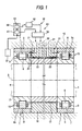
- Fig. 1 is a partially sectional view showing a portion of the machine tool in which a roller bearing according to the first embodiment of the present invention is used.
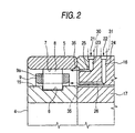
- Fig. 2 is an enlarged sectional view showing a primary portion of Fig. 1.
- the roller bearing 1 of this embodiment is a cylindrical roller bearing.
- a pair of cylindrical roller bearings 1 are arranged on opposite sides in the axial direction of the drive shaft 2 of the machine tool so that the drive shaft 2 can be rotatably supported.
- the structure of the bearing on one side is the same as the structure of the bearing on the other side. Therefore, the bearing 1 on one side is shown in Fig. 2.
- the roller bearing 1 includes: an inner ring member 4, into which the drive shaft 2 is press-fitted, and which is supported rotatably about the axis 3; an outer ring member 5 arranged concentrically with the inner ring member 4; a plurality of cylindrical rollers 8 arranged between the inner ring raceway surface 6 of the inner ring member 4 and the outer ring raceway surface 7 of the outer ring member 5 in such a manner that the cylindrical rollers 8 can be freely rolled; and a cage 9 having pockets 9a for holding these cylindrical rollers 8 at regular intervals in the circumferential direction.
- the outer ring member 5 is arranged and fixed to the inner circumferential face of the housing 10.
- the shoulder portions 15, the diameters of the outer circumferential faces of which are larger than the diameter of the inner ring raceway surface 6, are formed on opposite sides of the inner ring raceway surface 6 of the inner ring member 4 in the axial direction.
- the cylindrical outer ring spacer 16 is interposed between the outer ring members 5, and the inner ring spacer 17 is interposed between the inner ring members 4.
- the inner ring member 4 rotates about the axis 3, and the cylindrical rollers 8 roll between the inner ring raceway surface 6 and the outer ring raceway surface 7.
- the inside of the bearing must be lubricated.
- This lubricating device 20 includes a lubricant supply path arranged on the roller bearing 1 side of the outer ring spacer 16.
- This lubricant supply path includes a first lubricant supply path 21 and a second lubricant supply path 22.
- the first lubricant supply path 21 and the second lubricant supply path 22 respectively include: the large diameter paths 23, 24 formed in the outer ring spacer 16 in the radial direction; and the small diameter paths 25, 26 formed in the axial direction in the outer ring spacer 16 from the inward end portions in the radial direction of the large diameter paths 23, 24 to the roller bearing side.
- the large path 24 of the second lubricant supply path 22 is longer than the large path 23 of the first lubricant supply path 21.
- the end portion of the small diameter path 25 of the first lubricant supply path 21 is arranged close to the outer ring member 5 in such a manner as to be opened toward the inner circumferential face end portion of the outer ring member 5 in the axial direction.
- the end portion of the small diameter path 26 of the second lubricant supply path 22 is arranged close to the inner ring member 4 in such a manner as to be opened toward the outer circumferential end portion of the inner ring member 4 in the axial direction.
- the lubricating device 20 includes a supply control device 36 for supplying lubricating oil 35 (oil and air) into the first supply path 30 and the second supply path 31.
- This supply control device 36 includes: a rotation detector 37 for detecting the rotating speed of the inner ring member 4; a changeover valve device 38 connected to the first supply path 30 and the second supply path 31; a control unit 39 electrically connected to the rotation detector 37 and the changeover valve device 38; and a lubricant supply pump 40.
- control unit 39 for example, a common one-chip microcomputer is used for the control unit 39 which includes: a changeover unit 41 for outputting a changeover signal to the changeover valve device 38 according to a rotating speed signal sent from the rotation detector 37; and a drive unit 42 for outputting a drive signal to the drive portion of the lubricant supply pump 40.
- the roller bearing device is composed of the roller bearing 1 and the lubricating device 20.
- the rotation detector 37 detects the rotating speed of the drive shaft 2 at all times while the machine tool is being driven. The thus detected rotating speed is outputted into the changeover unit 41 of the control unit 39 and also outputted into the drive unit 42. Further, a drive signal is outputted from the drive unit 42 into the drive portion of the lubricant pump 40.
- the changeover unit 41 In the case where the rotation detector 37 detects a rotating speed signal representing the rotating speed not more than a predetermined speed, that is, in the case where the inner ring member 4 (drive shaft 2) is rotating at a low rotating speed, the changeover unit 41 outputs a drive signal to the drive portion of the lubricant supply pump 40 via the drive unit 42, and the changeover unit 41 outputs a drive control signal to the drive portion of the changeover valve device 38 so that the lubricating oil 35 can be supplied to the first supply path 30 and the supply of the lubricating oil 35 to the second supply path 31 can be shut off.
- the lubricating oil 35 is supplied from the lubricant supply pump 40 into the first lubricant supply path 30 and the first lubricant path 21 via the changeover valve device 38. Therefore, the lubricating oil 35 is supplied from the opening of the first lubricant path 21 toward the outer ring raceway surface 7 side so that the inside of the roller bearing 1 can be lubricated by an appropriate quantity of lubricating oil 35.
- the changeover unit 41 outputs a drive signal to the drive portion of the lubricant pump 40 via the drive unit 42, and the changeover unit 41 outputs a drive signal to the drive portion of the changeover valve device 38 so that the lubricating oil 35 can be supplied to the first supply path 30 and the lubricating oil 35 can be also supplied to the second supply path 31.
- the lubricating oil 35 is supplied from the lubricant supply pump 40 into the first supply path 30 and the first lubricant supply path 21 via the changeover valve device 38. Therefore, the lubricating oil 35 is supplied from the opening of the first lubricant supply path 21 toward the outer ring raceway surface 7. At the same time, the lubricating oil 35 is supplied from the opening of the second supply path 31 and the second lubricant supply path 22 toward the inner ring raceway surface 6.
- the inside of the roller bearing 1 can be lubricated by a quantity of lubricating oil 35 appropriate for the high speed rotation.
- the rotation detector 37 detects that the rotating speed has changed from the high speed to the low speed
- the signal is output to the changeover valve device 38 via the drive unit 42, and the changeover valve device 38 can be changed over so that the supply of the lubricating oil 35 to the second supply path 31 can be shut off.
- the changeover valve device 38 is changed over so that only a current of air not containing the lubricating oil 35 can be supplied into the second supply path 31 for a predetermined period of time.
- the current of air not containing the lubricating oil 35 is discharged from the opening of the second lubricant supply path 22. Therefore, the lubricating oil 35 sticking onto the inner ring raceway surface 6 or the outer circumferential face of the inner ring raceway surface 4 is discharged outside the roller bearing 1 being blown by the current of air.
- a quantity of lubricating oil 35 appropriate for the rotation of low speed can be ensured inside the roller bearing 1, and an increase in the temperature of the raceway surface of the roller bearing 1 can be suppressed and the occurrence of seize can be prevented.
- a portion to which the lubricating oil 35 is supplied is selected according to the rotating speed of the inner ring member 4, and a necessary quantity of lubricating oil 35 can be supplied. Accordingly, an increase in the stirring resistance of the roller bearing 1 and a rise in the temperature of the raceway surface can be suppressed and the occurrence of seize can be prevented.
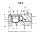
- the roller bearing of the second embodiment of the present invention includes: an outer ring member 5; an inner ring member 4; a plurality of cylindrical rollers 8; and a cage 9.
- the structure of the inner ring member 4 is the same as that of the first embodiment. Therefore, same reference marks are used to indicate like parts, and the explanations are omitted here.
- the cage 9 has annular portions 9b to be guided which are protruded outside in the radial direction and arranged on opposite sides of the pockets 9a in the axial direction.
- This cage 9 is an outer ring guide cage in which the outer circumferential faces 9c of the portions 9b are guided by the inner circumferential face of the outer ring member 5.
- the lubricating device 20 includes lubricant supply paths 45 which are formed in the radial direction at predetermined positions of the outer ring member 5 in the circumferential direction. These lubricant supply paths 45 are formed in the radial direction in portions of the outer ring member 5 in such a manner as to be opposed to and agree with the portions 9b to be guided in the axial direction. Accordingly, two lubricant supply paths 45 are formed in such a manner as to form a pair in the axial direction.
- the lubricating device 20 has a lubricant supply path 46 formed in the outer ring spacer 16.
- This lubricant supply path 46 includes: a large diameter portion 47 formed in the outer ring spacer 16 in the radial direction; and a small diameter portion 48 formed from the inward end portion in the radial direction of this large diameter portion 47 toward the outer circumferential face side of the inner ring member 4 of the roller bearing 1.
- first supply paths 49 and a second supply path 50 which are respectively communicated with the lubricant supply paths 45 and 46, are formed.
- the lubricating device 20 has the supply control unit 36 for supplying the lubricating oil 35 (oil and air) to the first supply path 49 and the second supply path 50.
- the changeover valve device 38 of the second embodiment has the constitution in which, according to a signal sent from the changeover unit 41, either first supply path 49 or second supply path 50 is selected or both the first supply path 49 and the second supply path 50 are selected, so that the first supply path 49 or the second supply path 50 can be supplied with the lubricating oil 35 or both the first supply path 49 and the second supply path 50 can be supplied with the lubricating oil 35.
- Other points of this embodiment are the same as those of the first embodiment described before. Therefore, same reference marks are used to indicate like parts, and the explanations are omitted here.
- the changeover unit 11 outputs a drive signal to the drive portion of the lubricant supply pump 40 via the drive unit 42, and the changeover unit 41 outputs a drive control signal to the drive portion of the changeover valve device 38 so that the lubricating oil 35 can be supplied to the first supply path 49 and the supply of the lubricating oil 35 to the second supply path 50 can be shut off.
- the lubricating oil 35 is supplied from the lubricant supply pump 40 into the first supply path 49 and from the opening of the lubricant supply path 45 to the outer circumferential face 9c of the portion 9b of the cage 9, that is, the lubricating oil 35 is discharged toward the face to be guided, so that the inside of the roller bearing 1 can be lubricated by an appropriate quantity of lubricating oil 35.
- the changeover unit 41 outputs a drive signal to the drive portion of the lubricant pump 40 via the drive unit 42, and the changeover unit 41 outputs a drive signal to the drive portion of the changeover valve device 38 so that the lubricating oil 35 can be supplied to the first supply path 49 and the lubricating oil 35 can be also supplied to the second supply path 50.
- the lubricating oil 35 is supplied from the lubricant supply pump 40 into the first supply path 49 and the lubricant supply path 45 via the changeover valve device 38. Therefore, the lubricating oil 35 is supplied from the opening of the lubricant supply path 45 toward the outer circumferential face 9c of the portion 9b. At the same time, the lubricating oil 35 is supplied from the second supply path 50 to the lubricant supply path 46. The lubricating oil 35 is discharged from its opening toward the inner ring raceway surface 6. In virtue of the foregoing, the inside of the roller bearing 1 can be lubricated by a quantity of lubricating oil 35 appropriate for the high speed rotation.
- the rotation detector 37 detects that the rotating speed has changed from the high speed to the low speed
- the signal is outputted to the changeover valve device 38 via the drive unit 42 and the lubricant supply pump 40, and the changeover valve device 38 can be changed over so that the supply of the lubricating oil 35 to the second supply path 50 can be shut off.
- the changeover valve device 38 is changed over so that only a current of air not containing the lubricating oil 35 can be supplied into the second supply path 50 for a predetermined period of time.
- the roller bearing 1 of the roller bearing device of the third embodiment includes shoulder portions 55, the diameter of the inner circumferential face of which is smaller than the diameter of the outer ring raceway surface 7, and which is provided on opposite sides of the outer ring raceway surface 7 of the outer ring member 5.
- the lubricating device 20 includes a pair of lubricant supply path 56, which are arranged at the boundary portions between the outer ring raceway 7 and the shoulder portions 55, from which the lubricating oil 35 is discharged toward the outer ring raceway surface 7. In each lubricant supply path 56, the supply path 57 provided in the housing 10 is formed. These supply paths 57 are connected to the changeover valve device 38. Other points of the structure of the lubricating device 20 are the same as those of the second embodiment described before.
- the changeover unit 41 in the case where the rotation detector 37 detects a rotating speed signal representing the rotating speed not more than a predetermined speed, that is, in the case where the inner ring member 4 (drive shaft 2) is rotating at a low rotating speed, the changeover unit 41 outputs a drive signal to the drive portion of the lubricant supply pump 40 via the drive unit 42, and the changeover unit 41 outputs a drive control signal to the drive portion of the changeover valve device 38 so that the lubricating oil 35 can be supplied to the first supply path 49 and the supply path 57 and so that the lubricating oil 35 can be supplied to the lubricant supply paths 45, 56. Further, the changeover unit 41 also outputs a drive signal to the drive portion of the changeover valve device 38 so that the supply of the lubricating oil 35 to the second supply path 50 can be shut off.
- the lubricating oil 35 is discharged toward the outer circumferential face 9c of the portion 9b of the cage 9 and the inner ring raceway surface 7, so that the inside of the roller bearing 1 can be lubricated by an appropriate quantity of lubricating oil 35.
- the changeover unit 41 outputs a drive signal to the drive portion of the lubricant pump 40 via the drive unit 42, and the changeover unit 41 also outputs a drive signal to the drive portion of the changeover valve device 38 so that the lubricating oil 35 can be supplied to the first supply path 49 and the supply path 57 and so that the lubricating oil 35 can be also supplied to the second supply path 50.
- the lubricating oil 35 is supplied to the outer circumferential face 9c of the portion 9b of the cage 9, the outer ring raceway surface 7 and the inner ring raceway surface 6, so that the inside of the roller bearing 1 can be lubricated by an appropriate quantity of lubricating oil 35.
- the rotation detector 37 detects that the rotating speed has changed from the aforementioned high speed to the low speed
- the signal is outputted to the changeover valve device 38 via the drive unit 42 and the lubricant supply pump 40, and the changeover valve device 38 can be changed over so that the supply of the lubricating oil 35 to the second supply path 50 can be shut off.
- the changeover valve device 38 is changed over so that only a current of air not containing the lubricating oil 35 can be supplied into the second supply path 50 for a predetermined period of time.
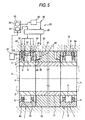
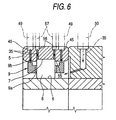
- the bearing device 1 of the present invention includes a double row cylindrical roller bearing 60, the inner ring member 4 of which has the shoulder portions.
- the cylindrical rollers 8, 8 are held in the pockets 9a of the cage 9 and arranged at regular intervals in the circumferential direction.
- the cage 9 is an outer ring guide cage.
- Each cage 9 is provided with an annular portion 9b to be guided arranged in an outward portion in the axial direction in such a manner that the annular portion 9b protrudes outward in the radial direction.
- two lubricant supply portions 45 for supplying the lubricating oil 35 onto the outer circumferential face 9c of the portion 9b are formed in such a manner that the two lubricant supply portions 45 make a pair in the axial direction.
- the supply path 62 communicating with the lubricant supply path 45 is formed.
- the lubricant supply path 61 for supplying the lubricating oil 35 onto the outer ring raceway surface 7 is formed in the radial direction.
- the supply path 63 communicating with the lubricant supply path 61 is formed in the housing 10.
- the lubricant supply path 64 for injecting the lubricating oil 35 onto opposite sides of the outer circumferential face of the double row cylindrical roller bearing 60 is formed.
- the supply path 65 communicating with the lubricant supply path 64 is formed.
- the supply paths 62, 63, 65 are connected to the changeover valve device 38.
- the control unit 39 of the supply control unit 36 of the lubricating device 20 drives the changeover valve device 38 so that the lubricating oil 35 can be supplied to the supply paths 62, 63 at the time of operation of a low rotating speed.
- the control unit 39 of the supply control unit 36 of the lubricating device 20 drives the changeover valve device 38 so that the lubricating oil 35 can be supplied to the supply paths 62, 63, 65 at the time of operation of a high rotating speed.
- the lubricating oil 35 is supplied toward the outer circumferential face 9c of the portion 9b of the cage 9.
- the lubricating oil 35 is supplied toward the outer circumferential face 9c of the portion 9b of the cage 9, the outer ring raceway surface 7 and the inner ring raceway surface 6. In this way, the inside of the roller bearing 1 can be lubricated by an appropriate quantity of lubricating oil 35.
- the control unit 39 drives the changeover valve device 38 so that the lubricating oil 35 can be supplied to the supply paths 62, 63 and so that an air current not containing the lubricating oil 35 can be supplied for a predetermined period of time.
- a redundant quantity of lubricating oil 35 which is supplied to the inner ring raceway surface 6 side at the time of rotating at a high speed can be removed to a predetermined position.
- other points of the structure of the supply control unit 36 are the same as those of the above embodiments. Therefore, the explanations are omitted here.
- a portion to which the lubricating oil is supplied is selected according to the rotating speed of the inner ring member. Therefore, the inside of the bearing can be lubricated in quick response by an appropriate quantity of lubricating oil. Further, it is possible to prevent an increase in the stirring resistance of the roller bearing. Therefore, a rise in the temperature of the roller bearing can be prevented.
Landscapes
- Engineering & Computer Science (AREA)
- General Engineering & Computer Science (AREA)
- Mechanical Engineering (AREA)
- Physics & Mathematics (AREA)
- General Physics & Mathematics (AREA)
- Rolling Contact Bearings (AREA)
Abstract
Description
Claims (5)
- A bearing device comprising:an inner ring member through which a shaft is passed and which is supported rotatably about an axis of the shaft and includes an inner ring raceway surface;an outer ring member arranged concentrically with the inner ring member and including an outer ring raceway surface;a plurality of rollers arranged rollably between the inner ring raceway surface and the outer ring raceway surface;a lubricating path through which lubricant is supplied to at least one of the inner ring raceway surface and the outer ring raceway surface; anda lubricating device which supplies the lubricant to the lubricating path according to rotating speed of the inner ring member about the axis.
- The bearing device according to claim 1, whereinthe lubricating path includes first and second lubricating paths, andthe lubricating device includes a rotation detector for detecting the rotating speed of the inner ring member, a changeover valve device connected to the first and second lubricating path and a controller for controlling the changeover valve device according to a detecting result of the rotation detector.
- The bearing device according to claim 2, wherein the controller controls the changeover valve device so that the lubricant is supplied to one of the first and second lubricating paths when the rotating speed of the inner ring member is no more than a predetermined speed, and is supplied to the first and second lubricating paths when the rotating speed of the inner ring member is higher than the predetermined speed.
- A method of lubricating a bearing device including an inner ring member through which a shaft is passed and which is supported rotatably about an axis of the shaft and includes an inner ring raceway surface, an outer ring member arranged concentrically with the inner ring member and including an outer ring raceway surface, a plurality of rollers arranged rollably between the inner ring raceway surface and the outer ring raceway surface, and a lubricating path through which lubricant is supplied to at least one of the inner ring raceway surface and the outer ring raceway surface, the method comprising the steps of:detecting a rotating speed of the inner ring member about the axis; andsupplying the lubricant to the lubricating path according to the detected rotating speed of the inner ring member.
- The method according to claim 4, whereinthe lubricating path includes first and second lubricating paths, andthe lubricant is supplied to one of the first and second lubricating paths when the rotating speed of the inner ring member is no more than a predetermined speed, and is supplied to the first and second lubricating paths when the rotating speed of the inner ring member is higher than the predetermined speed.
Applications Claiming Priority (2)
| Application Number | Priority Date | Filing Date | Title |
|---|---|---|---|
| JP2003122480A JP4151472B2 (en) | 2003-04-25 | 2003-04-25 | Roller bearing device and lubrication method for roller bearing |
| JP2003122480 | 2003-04-25 |
Publications (3)
| Publication Number | Publication Date |
|---|---|
| EP1471275A2 true EP1471275A2 (en) | 2004-10-27 |
| EP1471275A3 EP1471275A3 (en) | 2006-08-23 |
| EP1471275B1 EP1471275B1 (en) | 2009-01-07 |
Family
ID=32959715
Family Applications (1)
| Application Number | Title | Priority Date | Filing Date |
|---|---|---|---|
| EP04009736A Expired - Lifetime EP1471275B1 (en) | 2003-04-25 | 2004-04-23 | Roller bearing device and method of lubricating roller bearing |
Country Status (4)
| Country | Link |
|---|---|
| US (2) | US7500311B2 (en) |
| EP (1) | EP1471275B1 (en) |
| JP (1) | JP4151472B2 (en) |
| DE (1) | DE602004018868D1 (en) |
Cited By (10)
| Publication number | Priority date | Publication date | Assignee | Title |
|---|---|---|---|---|
| DE102007022163A1 (en) * | 2007-05-11 | 2008-11-13 | Martin Aschenbrenner | Abschmierbare multiple storage |
| DE102011089149A1 (en) * | 2011-12-20 | 2013-06-20 | Mtu Aero Engines Gmbh | Bearing arrangement for turbo-machine e.g. gas turbine of aircraft, has actuating element that expands reversibly with temperature increase of storage chamber to change cross section of lubricant passage |
| EP2333368A4 (en) * | 2008-10-03 | 2016-05-04 | Jtekt Corp | Rolling bearing |
| CN106523532A (en) * | 2016-12-26 | 2017-03-22 | 河南科技大学 | Oil-gas lubrication bearing pedestal with two-way nozzles, and using method of oil-gas lubrication bearing pedestal |
| CN112413379A (en) * | 2020-12-08 | 2021-02-26 | 康锰 | Rolling bearing |
| CN113757260A (en) * | 2021-10-09 | 2021-12-07 | 丽水市恒立机械制造有限公司 | Oil lubricating device for high-speed rotating bearing in bearing block |
| CN114838058A (en) * | 2022-05-25 | 2022-08-02 | 江苏欧斯特精密机械有限公司 | Motor bearing state monitoring and early warning device and heat dissipation and lubrication device for bearing |
| CN114941655A (en) * | 2022-05-13 | 2022-08-26 | 马鞍山经纬回转支承有限公司 | Anti-breaking tooth type slewing bearing for solar equipment |
| US11473625B2 (en) | 2018-09-14 | 2022-10-18 | Gree Electric Appliances, Inc. Of Zhuhai | Liquid injection ring and refrigerant lubricated bearing assembly |
| CN117072551A (en) * | 2023-09-06 | 2023-11-17 | 启东市供销机械有限公司 | A kind of radial thrust bearing |
Families Citing this family (38)
| Publication number | Priority date | Publication date | Assignee | Title |
|---|---|---|---|---|
| CN100510448C (en) * | 2004-10-08 | 2009-07-08 | Ntn株式会社 | Rolling bearing |
| JP2007113780A (en) * | 2005-09-21 | 2007-05-10 | Komori Corp | Rotating body oiling device |
| US7874733B2 (en) * | 2006-01-05 | 2011-01-25 | Ntn Corporation | Rolling bearing |
| JP4653040B2 (en) | 2006-08-24 | 2011-03-16 | オークマ株式会社 | Bearing and bearing device |
| JP2008087117A (en) * | 2006-10-03 | 2008-04-17 | Okuma Corp | Spindle lubricator |
| JP4993688B2 (en) * | 2006-11-15 | 2012-08-08 | オークマ株式会社 | Spindle lubricator |
| JP5053719B2 (en) * | 2007-06-07 | 2012-10-17 | オークマ株式会社 | Bearing lubrication equipment |
| JP5064978B2 (en) * | 2007-11-20 | 2012-10-31 | オークマ株式会社 | Operation confirmation method of bearing lubrication device |
| GB0801845D0 (en) * | 2008-02-01 | 2008-03-05 | Cummins Turbo Tech Ltd | A Shaft bearing assembly |
| JP4930453B2 (en) * | 2008-05-12 | 2012-05-16 | トヨタ自動車株式会社 | Bearing lubrication structure of rotating shaft |
| JP5233561B2 (en) * | 2008-10-03 | 2013-07-10 | 株式会社ジェイテクト | Rolling bearing |
| JP5353432B2 (en) * | 2009-05-14 | 2013-11-27 | 株式会社ジェイテクト | Rolling bearing device |
| JP5752879B2 (en) * | 2009-11-02 | 2015-07-22 | 株式会社荏原製作所 | Rotating machine |
| JP5561069B2 (en) * | 2009-12-17 | 2014-07-30 | 株式会社ジェイテクト | Bearing device |
| US8910751B2 (en) * | 2010-06-08 | 2014-12-16 | Flanders Electric Motor Service, Inc. | Bearing lubrication system |
| EP2602026A4 (en) * | 2010-08-17 | 2013-10-02 | Tomoe Kogyo Kk | Decanter centrifuge provided with continuous greasing device |
| DE102010063391A1 (en) * | 2010-12-17 | 2012-06-21 | Schaeffler Technologies Gmbh & Co. Kg | Bearing arrangement for fast rotating shafts of machines |
| JP5821781B2 (en) * | 2012-05-29 | 2015-11-24 | 株式会社ジェイテクト | Rolling bearing device |
| JP6009296B2 (en) * | 2012-09-24 | 2016-10-19 | Ntn株式会社 | Cooling structure of bearing device |
| EP2910806B1 (en) | 2012-09-24 | 2021-05-19 | NTN Corporation | Bearing device with a cooling structure |
| US8616777B1 (en) | 2012-11-16 | 2013-12-31 | Pratt & Whitney Canada Corp. | Bearing assembly with inner ring |
| JP6215569B2 (en) * | 2013-05-10 | 2017-10-18 | Ntn株式会社 | Rolling bearing device |
| DE102013108407A1 (en) * | 2013-08-05 | 2015-02-05 | Linde Hydraulics Gmbh & Co. Kg | Hydrostatic axial piston machine |
| DE102013114510A1 (en) * | 2013-12-19 | 2015-06-25 | Gea Mechanical Equipment Gmbh | Bearing arrangement for centrifuges |
| FR3015599B1 (en) * | 2013-12-23 | 2016-07-22 | Skf Aerospace France | MECHANICAL DEVICE COMPRISING A BEARING AND A LUBRICATION SYSTEM, MACHINE AND METHOD FOR IMPLEMENTING SAID METHOD |
| DE102014204062A1 (en) * | 2014-03-06 | 2015-09-10 | Aktiebolaget Skf | Lubricating system for a bearing and bearing with a lubrication system and method for lubricating a bearing |
| DE102014212620B4 (en) * | 2014-06-30 | 2019-02-14 | Schaeffler Technologies AG & Co. KG | Radial rolling bearing of an exhaust gas turbocharger |
| US9874244B2 (en) * | 2015-02-13 | 2018-01-23 | United Technologies Corporation | Bearing with integrated oil delivery system |
| DE102015210242B4 (en) * | 2015-06-03 | 2022-08-25 | Schaeffler Technologies AG & Co. KG | Wheel bearing arrangement for a vehicle |
| DE102015215302B4 (en) * | 2015-08-11 | 2026-03-12 | Aktiebolaget Skf | Automatic lubrication system for a bearing and method for operating an automatic lubrication system |
| US9909621B2 (en) * | 2016-02-23 | 2018-03-06 | Schaeffler Technologies AG & Co. KG | Bearing with integral grease groove reservoirs |
| US11022174B2 (en) | 2018-09-28 | 2021-06-01 | Rolls-Royce Corporation | Drain arrangement for a squeeze film damper |
| CN111173915A (en) * | 2018-12-28 | 2020-05-19 | 中车戚墅堰机车车辆工艺研究所有限公司 | Gearbox for rail vehicle with new bearing arrangement |
| CN112412987A (en) * | 2020-11-27 | 2021-02-26 | 江苏当升智能装备科技有限公司 | Oiling method for tile seat in intelligent equipment |
| CN112664566A (en) * | 2020-12-04 | 2021-04-16 | 国家电投集团广西兴安风电有限公司 | Bearing grease lubrication monitoring and determining method and system |
| CN112664567A (en) * | 2020-12-04 | 2021-04-16 | 国家电投集团广西兴安风电有限公司 | Automatic bearing lubrication control method and device |
| TWI830130B (en) * | 2021-02-25 | 2024-01-21 | 日商發那科股份有限公司 | Machinery with lubrication chamber |
| CN114776715A (en) * | 2022-04-21 | 2022-07-22 | 洛阳轴承研究所有限公司 | Spacer assembly and bearing assembly |
Family Cites Families (15)
| Publication number | Priority date | Publication date | Assignee | Title |
|---|---|---|---|---|
| US2747945A (en) * | 1954-03-04 | 1956-05-29 | United Aircraft Corp | Lubricating means |
| US4222283A (en) * | 1978-04-27 | 1980-09-16 | General Motors Corporation | Manual transmission lubrication system |
| US4527661A (en) * | 1981-10-29 | 1985-07-09 | Kearney & Trecker Corporation | Adaptive control system for machine tool or the like |
| US4738336A (en) * | 1987-04-27 | 1988-04-19 | Honeywell, Inc. | Controlled replenishing lubrication system |
| US5106209A (en) * | 1991-08-07 | 1992-04-21 | General Electric Company | Multi-plane lubricated bearing assembly |
| JPH0560145A (en) | 1991-08-27 | 1993-03-09 | Hitachi Seiko Ltd | Rolling bearing |
| JP3452947B2 (en) * | 1993-03-10 | 2003-10-06 | 株式会社森精機製作所 | Bearing lubrication mechanism of main shaft device |
| JPH08270660A (en) | 1995-03-29 | 1996-10-15 | Ntn Corp | Conical roller bearing device |
| US5671825A (en) * | 1996-11-19 | 1997-09-30 | The United States Of America As Represented By The Secretary Of The Navy | Shielded bearing lubrication |
| FR2775035B1 (en) | 1998-02-18 | 2000-03-10 | Snecma | STEERING THE RADIAL SET OF A BEARING |
| US6623251B2 (en) * | 1999-06-21 | 2003-09-23 | Nsk Ltd. | Spindle apparatus |
| DE19959472A1 (en) * | 1999-12-10 | 2001-06-21 | Sundwig Gmbh | Rolling bearing for a shaft or roller and method for lubricating such a rolling bearing |
| NL1014210C2 (en) | 2000-01-27 | 2001-07-30 | Skf Eng & Res Centre Bv | Intelligent bearing maintenance. |
| DE10047405A1 (en) * | 2000-09-26 | 2002-04-11 | Daimler Chrysler Ag | Turbocharger, in particular exhaust gas turbocharger for an internal combustion engine |
| FR2880930B1 (en) * | 2005-01-17 | 2007-03-02 | Snecma Moteurs Sa | A BEARING ASSEMBLY COMPRISING A DOUBLE INJECTION OF LUBRICATING LIQUID, AND AERONAUTICAL EQUIPMENT COMPRISING AT LEAST ONE SUCH ASSEMBLY |
-
2003
- 2003-04-25 JP JP2003122480A patent/JP4151472B2/en not_active Expired - Fee Related
-
2004
- 2004-04-23 EP EP04009736A patent/EP1471275B1/en not_active Expired - Lifetime
- 2004-04-23 US US10/829,990 patent/US7500311B2/en not_active Expired - Fee Related
- 2004-04-23 DE DE602004018868T patent/DE602004018868D1/en not_active Expired - Lifetime
-
2009
- 2009-01-07 US US12/318,725 patent/US20090129714A1/en not_active Abandoned
Cited By (13)
| Publication number | Priority date | Publication date | Assignee | Title |
|---|---|---|---|---|
| DE102007022163A1 (en) * | 2007-05-11 | 2008-11-13 | Martin Aschenbrenner | Abschmierbare multiple storage |
| EP2333368A4 (en) * | 2008-10-03 | 2016-05-04 | Jtekt Corp | Rolling bearing |
| DE102011089149A1 (en) * | 2011-12-20 | 2013-06-20 | Mtu Aero Engines Gmbh | Bearing arrangement for turbo-machine e.g. gas turbine of aircraft, has actuating element that expands reversibly with temperature increase of storage chamber to change cross section of lubricant passage |
| DE102011089149B4 (en) * | 2011-12-20 | 2014-06-26 | MTU Aero Engines AG | Bearing arrangement, in particular for a turbomachine |
| CN106523532A (en) * | 2016-12-26 | 2017-03-22 | 河南科技大学 | Oil-gas lubrication bearing pedestal with two-way nozzles, and using method of oil-gas lubrication bearing pedestal |
| US11473625B2 (en) | 2018-09-14 | 2022-10-18 | Gree Electric Appliances, Inc. Of Zhuhai | Liquid injection ring and refrigerant lubricated bearing assembly |
| EP3795829B1 (en) * | 2018-09-14 | 2024-08-21 | Gree Electric Appliances, Inc. of Zhuhai | Liquid spraying ring and refrigerant lubricating bearing assembly |
| CN112413379A (en) * | 2020-12-08 | 2021-02-26 | 康锰 | Rolling bearing |
| CN113757260A (en) * | 2021-10-09 | 2021-12-07 | 丽水市恒立机械制造有限公司 | Oil lubricating device for high-speed rotating bearing in bearing block |
| CN114941655A (en) * | 2022-05-13 | 2022-08-26 | 马鞍山经纬回转支承有限公司 | Anti-breaking tooth type slewing bearing for solar equipment |
| CN114941655B (en) * | 2022-05-13 | 2024-02-13 | 马鞍山经纬回转支承股份有限公司 | Anti-tooth breakage slewing bearing for solar equipment |
| CN114838058A (en) * | 2022-05-25 | 2022-08-02 | 江苏欧斯特精密机械有限公司 | Motor bearing state monitoring and early warning device and heat dissipation and lubrication device for bearing |
| CN117072551A (en) * | 2023-09-06 | 2023-11-17 | 启东市供销机械有限公司 | A kind of radial thrust bearing |
Also Published As
| Publication number | Publication date |
|---|---|
| US7500311B2 (en) | 2009-03-10 |
| US20040213494A1 (en) | 2004-10-28 |
| EP1471275B1 (en) | 2009-01-07 |
| JP4151472B2 (en) | 2008-09-17 |
| JP2004324811A (en) | 2004-11-18 |
| US20090129714A1 (en) | 2009-05-21 |
| EP1471275A3 (en) | 2006-08-23 |
| DE602004018868D1 (en) | 2009-02-26 |
Similar Documents
| Publication | Publication Date | Title |
|---|---|---|
| US7500311B2 (en) | Method of lubricating roller bearing | |
| EP0458499B1 (en) | Apparatus for cooling a spindle bearing of a machine | |
| US6733181B2 (en) | Bearing unit | |
| US6176349B1 (en) | Bearing lubricating device | |
| JP5098564B2 (en) | Cylindrical roller bearings and spindles for machine tools | |
| US6761483B1 (en) | Combined radial-axial slide bearing | |
| JP2001208085A (en) | Lubrication device for rolling bearing device | |
| US20060193545A1 (en) | Rolling element bearing cage with improved pilot surface lubrication | |
| JP2009138897A (en) | Rolling bearing and its lubrication method | |
| KR20190028780A (en) | Ball bearings, spindle devices and machine tools | |
| JP2011106493A (en) | Rolling bearing device | |
| JP5018334B2 (en) | Rolling bearing device | |
| JP4967917B2 (en) | Roller bearing and roller bearing device | |
| JP2001165177A (en) | Bearing lubricating device | |
| JP2008032090A (en) | Bearing oil-feeding device and rotary shaft supporting structure of wind turbine generator | |
| JP4327670B2 (en) | Cylindrical roller bearing | |
| JP6539507B2 (en) | Bearing unit | |
| JPH11132244A (en) | Cylindrical roller bearing device with lubrication device | |
| JP4341743B2 (en) | Roller bearing | |
| JP2008261357A (en) | Rotating shaft supporting structure of wind generator | |
| JPH10184705A (en) | Grease feeding device for bearing | |
| JP2003232372A (en) | Bearing device and spindle device | |
| JP2000291664A (en) | Rolling bearing device | |
| JP2002005181A (en) | Lubrication device for rolling bearings | |
| JP4099634B2 (en) | Spindle device |
Legal Events
| Date | Code | Title | Description |
|---|---|---|---|
| PUAI | Public reference made under article 153(3) epc to a published international application that has entered the european phase |
Free format text: ORIGINAL CODE: 0009012 |
|
| AK | Designated contracting states |
Kind code of ref document: A2 Designated state(s): AT BE BG CH CY CZ DE DK EE ES FI FR GB GR HU IE IT LI LU MC NL PL PT RO SE SI SK TR |
|
| AX | Request for extension of the european patent |
Extension state: AL HR LT LV MK |
|
| RAP1 | Party data changed (applicant data changed or rights of an application transferred) |
Owner name: JTEKT CORPORATION |
|
| PUAL | Search report despatched |
Free format text: ORIGINAL CODE: 0009013 |
|
| RIC1 | Information provided on ipc code assigned before grant |
Ipc: F16C 19/52 20060101ALI20060707BHEP Ipc: F16C 33/66 20060101ALI20060707BHEP Ipc: G01P 3/44 20060101AFI20060707BHEP |
|
| AK | Designated contracting states |
Kind code of ref document: A3 Designated state(s): AT BE BG CH CY CZ DE DK EE ES FI FR GB GR HU IE IT LI LU MC NL PL PT RO SE SI SK TR |
|
| AX | Request for extension of the european patent |
Extension state: AL HR LT LV MK |
|
| 17P | Request for examination filed |
Effective date: 20070103 |
|
| 17Q | First examination report despatched |
Effective date: 20070207 |
|
| AKX | Designation fees paid |
Designated state(s): DE GB IT |
|
| GRAP | Despatch of communication of intention to grant a patent |
Free format text: ORIGINAL CODE: EPIDOSNIGR1 |
|
| GRAS | Grant fee paid |
Free format text: ORIGINAL CODE: EPIDOSNIGR3 |
|
| GRAA | (expected) grant |
Free format text: ORIGINAL CODE: 0009210 |
|
| AK | Designated contracting states |
Kind code of ref document: B1 Designated state(s): DE GB IT |
|
| REG | Reference to a national code |
Ref country code: GB Ref legal event code: FG4D |
|
| REF | Corresponds to: |
Ref document number: 602004018868 Country of ref document: DE Date of ref document: 20090226 Kind code of ref document: P |
|
| PLBE | No opposition filed within time limit |
Free format text: ORIGINAL CODE: 0009261 |
|
| STAA | Information on the status of an ep patent application or granted ep patent |
Free format text: STATUS: NO OPPOSITION FILED WITHIN TIME LIMIT |
|
| 26N | No opposition filed |
Effective date: 20091008 |
|
| PG25 | Lapsed in a contracting state [announced via postgrant information from national office to epo] |
Ref country code: IT Free format text: LAPSE BECAUSE OF FAILURE TO SUBMIT A TRANSLATION OF THE DESCRIPTION OR TO PAY THE FEE WITHIN THE PRESCRIBED TIME-LIMIT Effective date: 20090107 |
|
| PGFP | Annual fee paid to national office [announced via postgrant information from national office to epo] |
Ref country code: GB Payment date: 20110420 Year of fee payment: 8 |
|
| GBPC | Gb: european patent ceased through non-payment of renewal fee |
Effective date: 20120423 |
|
| PG25 | Lapsed in a contracting state [announced via postgrant information from national office to epo] |
Ref country code: GB Free format text: LAPSE BECAUSE OF NON-PAYMENT OF DUE FEES Effective date: 20120423 |
|
| PGFP | Annual fee paid to national office [announced via postgrant information from national office to epo] |
Ref country code: DE Payment date: 20170420 Year of fee payment: 14 |
|
| REG | Reference to a national code |
Ref country code: DE Ref legal event code: R119 Ref document number: 602004018868 Country of ref document: DE |
|
| PG25 | Lapsed in a contracting state [announced via postgrant information from national office to epo] |
Ref country code: DE Free format text: LAPSE BECAUSE OF NON-PAYMENT OF DUE FEES Effective date: 20181101 |