JP5561069B2 - Bearing device - Google Patents
Bearing device Download PDFInfo
- Publication number
- JP5561069B2 JP5561069B2 JP2010217017A JP2010217017A JP5561069B2 JP 5561069 B2 JP5561069 B2 JP 5561069B2 JP 2010217017 A JP2010217017 A JP 2010217017A JP 2010217017 A JP2010217017 A JP 2010217017A JP 5561069 B2 JP5561069 B2 JP 5561069B2
- Authority
- JP
- Japan
- Prior art keywords
- peripheral surface
- liquid lubricant
- vibration
- outer ring
- inner ring
- Prior art date
- Legal status (The legal status is an assumption and is not a legal conclusion. Google has not performed a legal analysis and makes no representation as to the accuracy of the status listed.)
- Expired - Fee Related
Links
Images


Classifications
-
- F—MECHANICAL ENGINEERING; LIGHTING; HEATING; WEAPONS; BLASTING
- F16—ENGINEERING ELEMENTS AND UNITS; GENERAL MEASURES FOR PRODUCING AND MAINTAINING EFFECTIVE FUNCTIONING OF MACHINES OR INSTALLATIONS; THERMAL INSULATION IN GENERAL
- F16C—SHAFTS; FLEXIBLE SHAFTS; ELEMENTS OR CRANKSHAFT MECHANISMS; ROTARY BODIES OTHER THAN GEARING ELEMENTS; BEARINGS
- F16C33/00—Parts of bearings; Special methods for making bearings or parts thereof
- F16C33/30—Parts of ball or roller bearings
- F16C33/66—Special parts or details in view of lubrication
- F16C33/6637—Special parts or details in view of lubrication with liquid lubricant
- F16C33/6659—Details of supply of the liquid to the bearing, e.g. passages or nozzles
- F16C33/667—Details of supply of the liquid to the bearing, e.g. passages or nozzles related to conditioning, e.g. cooling, filtering
-
- F—MECHANICAL ENGINEERING; LIGHTING; HEATING; WEAPONS; BLASTING
- F16—ENGINEERING ELEMENTS AND UNITS; GENERAL MEASURES FOR PRODUCING AND MAINTAINING EFFECTIVE FUNCTIONING OF MACHINES OR INSTALLATIONS; THERMAL INSULATION IN GENERAL
- F16C—SHAFTS; FLEXIBLE SHAFTS; ELEMENTS OR CRANKSHAFT MECHANISMS; ROTARY BODIES OTHER THAN GEARING ELEMENTS; BEARINGS
- F16C33/00—Parts of bearings; Special methods for making bearings or parts thereof
- F16C33/30—Parts of ball or roller bearings
- F16C33/66—Special parts or details in view of lubrication
- F16C33/6603—Special parts or details in view of lubrication with grease as lubricant
- F16C33/6607—Retaining the grease in or near the bearing
-
- F—MECHANICAL ENGINEERING; LIGHTING; HEATING; WEAPONS; BLASTING
- F16—ENGINEERING ELEMENTS AND UNITS; GENERAL MEASURES FOR PRODUCING AND MAINTAINING EFFECTIVE FUNCTIONING OF MACHINES OR INSTALLATIONS; THERMAL INSULATION IN GENERAL
- F16C—SHAFTS; FLEXIBLE SHAFTS; ELEMENTS OR CRANKSHAFT MECHANISMS; ROTARY BODIES OTHER THAN GEARING ELEMENTS; BEARINGS
- F16C33/00—Parts of bearings; Special methods for making bearings or parts thereof
- F16C33/30—Parts of ball or roller bearings
- F16C33/66—Special parts or details in view of lubrication
- F16C33/6603—Special parts or details in view of lubrication with grease as lubricant
- F16C33/6622—Details of supply and/or removal of the grease, e.g. purging grease
- F16C33/6625—Controlling or conditioning the grease supply
-
- F—MECHANICAL ENGINEERING; LIGHTING; HEATING; WEAPONS; BLASTING
- F16—ENGINEERING ELEMENTS AND UNITS; GENERAL MEASURES FOR PRODUCING AND MAINTAINING EFFECTIVE FUNCTIONING OF MACHINES OR INSTALLATIONS; THERMAL INSULATION IN GENERAL
- F16N—LUBRICATING
- F16N11/00—Arrangements for supplying grease from a stationary reservoir or the equivalent in or on the machine or member to be lubricated; Grease cups
-
- F—MECHANICAL ENGINEERING; LIGHTING; HEATING; WEAPONS; BLASTING
- F16—ENGINEERING ELEMENTS AND UNITS; GENERAL MEASURES FOR PRODUCING AND MAINTAINING EFFECTIVE FUNCTIONING OF MACHINES OR INSTALLATIONS; THERMAL INSULATION IN GENERAL
- F16N—LUBRICATING
- F16N2210/00—Applications
- F16N2210/14—Bearings
Landscapes
- Engineering & Computer Science (AREA)
- General Engineering & Computer Science (AREA)
- Mechanical Engineering (AREA)
- Rolling Contact Bearings (AREA)
- Lubricants (AREA)
Description
本発明は、例えば、高速回転する工作機械の主軸などを支持する軸受装置に関する。 The present invention relates to a bearing device that supports, for example, a spindle of a machine tool that rotates at a high speed.
軸受の代表的な潤滑の態様としてはグリース潤滑とオイル潤滑とがある。このオイル潤滑を行う軸受装置が、特開2002−130303号公報(特許文献1)に開示されている。 Typical lubrication modes of the bearing include grease lubrication and oil lubrication. A bearing device that performs this oil lubrication is disclosed in Japanese Patent Laid-Open No. 2002-130303 (Patent Document 1).
より詳しくは、上記軸受装置は、外部から玉軸受内に潤滑油を圧縮エアによって搬送して、玉軸受の軌道面や玉を潤滑する。このような潤滑では、外部から比較的低い温度の潤滑油を供給することで、玉軸受を内部から積極的に冷却する。これにより、上記玉軸受内で十分な潤滑油膜を形成することができる。 More specifically, the bearing device conveys lubricating oil from the outside into the ball bearing by compressed air to lubricate the raceway surface and the ball of the ball bearing. In such lubrication, the ball bearing is actively cooled from the inside by supplying lubricating oil having a relatively low temperature from the outside. Thereby, a sufficient lubricating oil film can be formed in the ball bearing.
しかしながら、上記従来の軸受装置には、外部から玉軸受内に潤滑油を圧縮エアによって搬送するため、潤滑油が玉軸受の周囲に飛散して、使用環境が劣悪になるという問題があった。 However, the conventional bearing device has a problem that since the lubricating oil is conveyed from the outside into the ball bearing by compressed air, the lubricating oil is scattered around the ball bearing and the usage environment is deteriorated.
一方、上記グリース潤滑は、軸受に封入したグリースによって軌道面などを潤滑するので、上記問題は生じないが、オイル潤滑に比べて攪拌抵抗が大きく、昇温が大きく、また、グリース寿命が比較的短くて、定期的なメンテナンスが必要であるなどの別の問題があった。そのため、高速回転をする工作機械の軸受には、グリース潤滑を使用し難くかった。 On the other hand, the grease lubrication lubricates the raceway and the like with the grease enclosed in the bearing, so the above problem does not occur. However, compared with oil lubrication, the stirring resistance is larger, the temperature rise is larger, and the grease life is relatively shorter. There were other problems such as being short and requiring regular maintenance. Therefore, it is difficult to use grease lubrication for machine tool bearings that rotate at high speed.
そこで、本発明の課題は、使用環境への負荷を低減でき、かつ、攪拌抵抗が小さくて、寿命が長く、メンテナンスフリーとすることが可能な軸受装置を提供することにある。 Therefore, an object of the present invention is to provide a bearing device that can reduce the load on the use environment, has a small stirring resistance, has a long life, and can be made maintenance-free.
上記課題を解決するため、本発明の軸受装置は、
内周面に軌道面を有する外輪と、
外周面に軌道面を有する内輪と、
上記外輪の上記軌道面と上記内輪の上記軌道面との間に配置された複数の転動体と、
上記複数の転動体を保持する保持器と、
上記外輪の上記内周面と上記内輪の上記外周面との間に液体潤滑剤を供給する液体潤滑剤供給装置と
を備え、
上記液体潤滑剤供給装置は、
上記外輪の上記内周面と上記内輪の上記外周面との間に連通する液体潤滑剤通路と、
上記液体潤滑剤通路から上記外輪の上記内周面と上記内輪の上記外周面との間に上記液体潤滑剤を供給するために、固体状、半固体状もしくは粘ちょう状の潤滑剤、または、潤滑剤含有樹脂組成物である非液体潤滑剤に当接して、上記非液体潤滑剤に振動を加えることができる加振装置と
を有し、
上記外輪と上記内輪との少なくとも一方の温度を検出する温度センサと、
上記温度センサが検出した温度に基づいて、上記加振装置を制御する制御装置と
を備え、
上記制御装置は、上記温度センサが検出した温度が第1温度であるときにおける上記加振装置の振動時間、振動数または振幅が、上記温度センサが検出した温度が上記第1温度とは異なる第2温度であるときにおける上記加振装置の振動時間、振動数または振幅と異なるように制御することを特徴としている。
In order to solve the above problems, the bearing device of the present invention provides:
An outer ring having a raceway surface on the inner peripheral surface;
An inner ring having a raceway surface on the outer peripheral surface;
A plurality of rolling elements disposed between the raceway surface of the outer ring and the raceway surface of the inner ring;
A cage for holding the plurality of rolling elements;
A liquid lubricant supply device for supplying a liquid lubricant between the inner peripheral surface of the outer ring and the outer peripheral surface of the inner ring;
The liquid lubricant supply device is
A liquid lubricant passage communicating between the inner peripheral surface of the outer ring and the outer peripheral surface of the inner ring;
In order to supply the liquid lubricant between the inner peripheral surface of the outer ring and the outer peripheral surface of the inner ring from the liquid lubricant passage, a solid, semi-solid or viscous lubricant, or the non-liquid lubricant is a lubricant-containing resin composition in contact, possess a vibrating can apply vibration to the non-liquid lubricant system,
A temperature sensor for detecting the temperature of at least one of the outer ring and the inner ring;
A control device for controlling the vibration exciter based on the temperature detected by the temperature sensor;
With
When the temperature detected by the temperature sensor is the first temperature, the control device has a vibration time, frequency or amplitude of the vibration exciter that is different from the first temperature. Control is performed so as to be different from the vibration time, frequency, or amplitude of the vibration exciter when the temperature is two .
上記構成によれば、上記加振装置が、固体状、半固体状もしくは粘ちょう状の潤滑剤、または、潤滑剤含有樹脂組成物である非液体潤滑剤に振動を加えると、非液体潤滑剤から油分が分離される。この油分は、液体潤滑剤通路を通って、外輪の内周面と内輪の外周面との間に入る。これにより、上記外輪の軌道面、内輪の軌道面、および、転動体が油分で潤滑される。 According to the above configuration, when the vibration device applies vibration to the solid, semi-solid or viscous lubricant, or the non-liquid lubricant that is a lubricant-containing resin composition, the non-liquid lubricant From which oil is separated. This oil component passes between the inner peripheral surface of the outer ring and the outer peripheral surface of the inner ring through the liquid lubricant passage. Thereby, the raceway surface of the outer ring, the raceway surface of the inner ring, and the rolling elements are lubricated with oil.
このように、上記油分を圧縮エアで送らないので、油分は飛散せず、使用環境への負荷を低減することができる。 Thus, since the said oil component is not sent with compressed air, an oil component does not scatter and the load to use environment can be reduced.
また、上記外輪の軌道面、内輪の軌道面、および、転動体を油分で潤滑するので、攪拌抵抗を小さくできて、寿命を長くでき、メンテナンスフリーとすることが可能である。 Also, since the outer ring raceway surface, the inner raceway raceway surface, and the rolling elements are lubricated with oil, the agitation resistance can be reduced, the life can be extended, and maintenance can be made free.
また、上記加振装置の振動によって、非液体潤滑剤からの油分の分離が促進されるので、外輪の内周面と内輪の外周面との間に入る油分の量を増やし、オイル潤滑と同等の性能の潤滑を行える。 In addition, the vibration of the vibration generator promotes the separation of oil from the non-liquid lubricant, so the amount of oil that enters between the inner peripheral surface of the outer ring and the outer peripheral surface of the inner ring is increased, equivalent to oil lubrication. The performance of lubrication can be done.
一実施形態の軸受装置では、
上記液体潤滑剤供給装置は、上記非液体潤滑剤を貯蔵する非液体潤滑剤貯蔵部を有し、
この非液体潤滑剤貯蔵部内に上記加振装置を配設した。
In the bearing device of one embodiment,
The liquid lubricant supply device has a non-liquid lubricant storage unit for storing the non-liquid lubricant,
The vibration exciter was disposed in the non-liquid lubricant reservoir.
上記実施形態によれば、上記非液体潤滑剤を貯蔵する非液体潤滑剤貯蔵部があるので、非液体潤滑剤の補充回数を減らし、メンテナンス性をさらに向上させることができる。 According to the embodiment, since there is a non-liquid lubricant storage unit that stores the non-liquid lubricant, it is possible to reduce the number of times the non-liquid lubricant is replenished and further improve the maintainability.
また、上記非液体潤滑剤貯蔵部内に加振装置を配設するので、装置を小型化することができる。 Further, since the vibration device is disposed in the non-liquid lubricant storage unit, the device can be miniaturized.
また、上記制御装置は、温度センサが検出した温度が第1温度であるときにおける加振装置の振動時間、振動数または振幅が、温度センサが検出した温度が第1温度とは異なる第2温度であるときにおける加振装置の振動時間、振動数または振幅と異なるように制御するので、温度センサが検出した温度に応じて、外輪の内周面と内輪の外周面との間に入る油分の量を調節することができる。 Further , the control device may be configured such that the vibration time, frequency, or amplitude of the vibration device when the temperature detected by the temperature sensor is the first temperature is the second temperature at which the temperature detected by the temperature sensor is different from the first temperature. Therefore, the oil content that enters between the inner peripheral surface of the outer ring and the outer peripheral surface of the inner ring is controlled according to the temperature detected by the temperature sensor. The amount can be adjusted.
本発明の軸受装置では、
内周面に軌道面を有する外輪と、
外周面に軌道面を有する内輪と、
上記外輪の上記軌道面と上記内輪の上記軌道面との間に配置された複数の転動体と、
上記複数の転動体を保持する保持器と、
上記外輪の上記内周面と上記内輪の上記外周面との間に液体潤滑剤を供給する液体潤滑剤供給装置と
を備え、
上記液体潤滑剤供給装置は、
上記外輪の上記内周面と上記内輪の上記外周面との間に連通する液体潤滑剤通路と、
上記液体潤滑剤通路から上記外輪の上記内周面と上記内輪の上記外周面との間に上記液体潤滑剤を供給するために、固体状、半固体状もしくは粘ちょう状の潤滑剤、または、潤滑剤含有樹脂組成物である非液体潤滑剤に当接して、上記非液体潤滑剤に振動を加えることができる加振装置と
を有し、
上記外輪または上記内輪の回転速度を検出する回転速度センサと、
上記回転速度センサが検出した回転速度に基づいて、上記加振装置を制御する制御装置と
を備え、
上記制御装置は、上記回転速度センサが検出した回転速度が第1回転速度における上記加振装置の振動時間、振動数または振幅が、上記回転速度センサが検出した回転速度が上記第1回転速度とは異なる第2回転速度における上記加振装置の振動時間、振動数または振幅と異なるように制御することを特徴としている。
In the bearing device of the present invention ,
An outer ring having a raceway surface on the inner peripheral surface;
An inner ring having a raceway surface on the outer peripheral surface;
A plurality of rolling elements disposed between the raceway surface of the outer ring and the raceway surface of the inner ring;
A cage for holding the plurality of rolling elements;
A liquid lubricant supply device for supplying a liquid lubricant between the inner peripheral surface of the outer ring and the outer peripheral surface of the inner ring;
With
The liquid lubricant supply device is
A liquid lubricant passage communicating between the inner peripheral surface of the outer ring and the outer peripheral surface of the inner ring;
In order to supply the liquid lubricant between the inner peripheral surface of the outer ring and the outer peripheral surface of the inner ring from the liquid lubricant passage, a solid, semi-solid or viscous lubricant, or A vibration device capable of applying vibration to the non-liquid lubricant in contact with the non-liquid lubricant that is a lubricant-containing resin composition;
Have
A rotational speed sensor for detecting the rotational speed of the outer ring or the inner ring ;
A control device for controlling the excitation device based on the rotation speed detected by the rotation speed sensor;
The control device is configured such that the rotation time detected by the rotation speed sensor is the first rotation speed, the vibration time, the vibration frequency, or the amplitude of the vibration exciter is the first rotation speed. Is characterized in that it is controlled to be different from the vibration time, frequency or amplitude of the vibration exciter at different second rotational speeds.
上記構成によれば、上記加振装置が、固体状、半固体状もしくは粘ちょう状の潤滑剤、または、潤滑剤含有樹脂組成物である非液体潤滑剤に振動を加えると、非液体潤滑剤から油分が分離される。この油分は、液体潤滑剤通路を通って、外輪の内周面と内輪の外周面との間に入る。これにより、上記外輪の軌道面、内輪の軌道面、および、転動体が油分で潤滑される。
このように、上記油分を圧縮エアで送らないので、油分は飛散せず、使用環境への負荷を低減することができる。
また、上記外輪の軌道面、内輪の軌道面、および、転動体を油分で潤滑するので、攪拌抵抗を小さくできて、寿命を長くでき、メンテナンスフリーとすることが可能である。
また、上記加振装置の振動によって、非液体潤滑剤からの油分の分離が促進されるので、外輪の内周面と内輪の外周面との間に入る油分の量を増やし、オイル潤滑と同等の性能の潤滑を行える。
また、上記制御装置は、回転速度センサが検出した回転速度が第1回転速度における加振装置の振動時間、振動数または振幅が、回転速度センサが検出した回転速度が第1回転速度とは異なる第2回転速度における加振装置の振動時間、振動数または振幅と異なるように制御するので、回転速度センサが検出した回転速度に応じて、外輪の内周面と内輪の外周面との間に入る油分の量を調節することができる。
一実施形態の軸受装置では、
上記液体潤滑剤供給装置は、上記非液体潤滑剤を貯蔵する非液体潤滑剤貯蔵部を有し、
この非液体潤滑剤貯蔵部内に上記加振装置を配設した。
上記実施形態によれば、上記非液体潤滑剤を貯蔵する非液体潤滑剤貯蔵部があるので、非液体潤滑剤の補充回数を減らし、メンテナンス性をさらに向上させることができる。
また、上記非液体潤滑剤貯蔵部内に加振装置を配設するので、装置を小型化することができる。
According to the above configuration, when the vibration device applies vibration to the solid, semi-solid or viscous lubricant, or the non-liquid lubricant that is a lubricant-containing resin composition, the non-liquid lubricant From which oil is separated. This oil component passes between the inner peripheral surface of the outer ring and the outer peripheral surface of the inner ring through the liquid lubricant passage. Thereby, the raceway surface of the outer ring, the raceway surface of the inner ring, and the rolling elements are lubricated with oil.
Thus, since the said oil component is not sent with compressed air, an oil component does not scatter and the load to use environment can be reduced.
Also, since the outer ring raceway surface, the inner raceway raceway surface, and the rolling elements are lubricated with oil, the agitation resistance can be reduced, the life can be extended, and maintenance can be made free.
In addition, the vibration of the vibration generator promotes the separation of the oil from the non-liquid lubricant. The performance of lubrication can be done.
In the control device, the vibration time, vibration frequency, or amplitude of the vibration exciter when the rotation speed detected by the rotation speed sensor is the first rotation speed is different from the rotation speed detected by the rotation speed sensor. Since the vibration is controlled so as to be different from the vibration time, vibration frequency or amplitude of the vibration device at the second rotation speed, according to the rotation speed detected by the rotation speed sensor, there is a gap between the inner peripheral surface of the outer ring and the outer peripheral surface of the inner ring The amount of oil that enters can be adjusted.
In the bearing device of one embodiment,
The liquid lubricant supply device has a non-liquid lubricant storage unit for storing the non-liquid lubricant,
The vibration exciter was disposed in the non-liquid lubricant reservoir.
According to the embodiment, since there is a non-liquid lubricant storage unit that stores the non-liquid lubricant, it is possible to reduce the number of times the non-liquid lubricant is replenished and further improve the maintainability.
Further, since the vibration device is disposed in the non-liquid lubricant storage unit, the device can be miniaturized.
本発明の軸受装置によれば、加振装置は、外輪の内周面と内輪の外周面との間に連通する液体潤滑剤通路から、その間に液体潤滑剤を供給するために、固体状、半固体状もしくは粘ちょう状の潤滑剤、または、潤滑剤含有樹脂組成物である非液体潤滑剤に当接して、非液体潤滑剤に振動を加えることができるので、非液体潤滑剤から油分を分離し、液体潤滑剤通路から外輪の内周面と内輪の外周面との間に送ることができる。 According to the bearing device of the present invention, the vibration device is in a solid state in order to supply the liquid lubricant from the liquid lubricant passage communicating between the inner peripheral surface of the outer ring and the outer peripheral surface of the inner ring. The non-liquid lubricant can be vibrated by contacting with a semi-solid or viscous lubricant or a non-liquid lubricant that is a lubricant-containing resin composition. It can isolate | separate and can send between the internal peripheral surface of an outer ring | wheel, and the outer peripheral surface of an inner ring | wheel from a liquid lubricant channel | path.
したがって、上記油分を圧縮エアで搬送しなくてよいので、油分の飛散を無くし、使用環境への負荷を低減することができる。 Therefore, since it is not necessary to convey the said oil component by compressed air, scattering of an oil component can be eliminated and the load to use environment can be reduced.
また、上記外輪の軌道面、内輪の軌道面、および、転動体を油分で潤滑するので、攪拌抵抗を小さくできて、寿命を長くでき、メンテナンスフリーとすることが可能である。 Also, since the outer ring raceway surface, the inner raceway raceway surface, and the rolling elements are lubricated with oil, the agitation resistance can be reduced, the life can be extended, and maintenance can be made free.
また、上記加振装置の振動によって、非液体潤滑剤からの油分の分離が促進されるので、外輪の内周面と内輪の外周面との間に入る油分の量を増やし、オイル潤滑と同等の性能の潤滑を行える。 In addition, the vibration of the vibration generator promotes the separation of oil from the non-liquid lubricant, so the amount of oil that enters between the inner peripheral surface of the outer ring and the outer peripheral surface of the inner ring is increased, equivalent to oil lubrication. The performance of lubrication can be done.
以下、本発明の軸受装置を図示の実施の形態により詳細に説明する。 The bearing device of the present invention will be described in detail below with reference to the illustrated embodiments.
〔第1実施形態〕
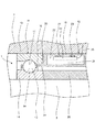
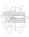
図1は、本発明の第1実施形態の軸受装置1を回転軸を含む面で切った概略断面図である。なお、本第1実施形態では軸受装置1を工作機械に用いている。
[First Embodiment]
FIG. 1 is a schematic cross-sectional view of a
上記軸受装置1は、工作機械の静止側のハウジング2に取り付けられ、工作機械の回転側の主軸3を支持している。この軸受装置1は、単列アンギュラ玉軸受11と、この単列アンギュラ玉軸受11内にグリース21の油分を供給する液体潤滑剤供給装置12とを具備する。なお、グリース21は非液体潤滑剤の一例であり、グリース21の油分は液体潤滑剤の一例である。
The
上記単列アンギュラ玉軸受11は、外輪13と、内輪14と、複数の玉15(図1においては1つのみ図示している)と、保持器16とを備える。なお、玉15は転動体の一例である。
The single-row
上記外輪13は工作機械のハウジング2に内嵌さている。この外輪13の内周面には、断面円弧形状の外輪側軌道溝17が形成されている。なお、外輪軌道溝17は、外輪が有する軌道面の一例である。
The
上記内輪14は工作機械の主軸3の外周面に外嵌されており、主軸3と共に同期回転する。また、内輪14の外周面には断面円弧形状の内輪側軌道溝18が形成されている。なお、内輪側軌道溝18は、内輪が有する軌道面の一例である。
The
上記複数の玉15は、外輪側軌道溝17と内輪側軌道溝18との間に配置され、外輪側軌道溝17,内輪側軌道溝18上を転動する。
The plurality of
上記保持器16は、図示しないが、周方向に所定間隔を隔てて形成された複数のポケットを有している。その各ポケットに玉15を1個づつ収容している。
Although not shown, the
上記液体潤滑剤供給装置12は、工作機械のハウジング2の内周面に内嵌する環状の外側間座19と、工作機械の主軸3の外周面に外嵌する環状の内側間座20と、外輪13の内周面と内輪14の外周面との間に連通する液体潤滑剤通路30と、外輪13の内周面と内輪14の外周面との間にグリース21の油分を供給するための加振装置24とを有する。
The liquid
上記外側間座19には、グリース21を貯留するグリース貯留部22が形成されている。グリース貯留部22内の空間は液体潤滑剤通路30を介して外輪13の内周面と内輪14の外周面との間の空間と連通する。そして、グリース貯留部22の内周面には、ゴム部材23を介して加振装置24が取り付けられている。つまり、グリース貯留部22内に加振装置24を配設している。なお、グリース貯留部22は非液体潤滑剤貯蔵部の一例である。
The
上記加振装置24は、グリース貯留部22内のグリース21に振動を加える。このような加振装置24の具体例としては、例えば、超音波発生器や、携帯電話に搭載されるバイブレータなどが挙げられる。また、加振装置24は、接続線25を介して、後述する制御装置27に接続されている。なお、加振装置24は、電池を搭載するものでもよいし、あるいは、電池を搭載していなくて外側間座19外から電力が供給されるものであってもよい。
The
上記グリース21は、合成炭化水素油などの基油(ベースオイル)と、例えばLi石けんなどの増ちょう剤とを含む潤滑グリース組成物である。この潤滑グリース組成物には、例えば、酸化防止剤、極圧剤、摩耗防止剤、さび止め剤、腐食防止剤、構造安定剤、固体潤滑剤などの添加剤を配合してもよい。
The
また、上記外側間座19の外輪13側の軸端面の内縁部には、軸方向に突出する突出部31が形成されている。この突出部31は、外輪13の内周面と内輪14の外周面との間に挿入される。そして、突出部31の外輪13側の表面に液体潤滑剤通路30の一部が形成されている。グリース21の基油は、毛細管現象によって、液体潤滑剤通路30を通ってアンギュラ玉軸受11内へ染み出るようになっている。この液体潤滑剤通路30のアンギュラ玉軸受11の端は外輪軌道溝17、内輪側軌道溝18および玉15の近傍に位置する。
A protruding
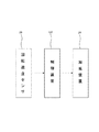
図2は上記軸受装置1の制御ブロック図である。
FIG. 2 is a control block diagram of the
上記軸受装置1は、外輪13および内輪14の少なくとも一方の温度を検出する温度センサ26と、この温度センサ26が検出した温度に基づいて、加振装置24をオンオフ制御する制御装置27を備える。この温度センサ26は、接触式、非接触式のどちらの方式であってもよい。
The
上記制御装置27は、温度センサ26の検出温度が第1温度であるときにおける加振装置24の振動時間(オン時間)、振動数または振幅が、温度センサ26の検出温度が第2温度であるときにおける加振装置24の振動時間、振動数または振幅と異なるように、加振装置24を制御する。ここで、上記第1温度および第2温度は予め設定された温度であり、第1温度は第2温度と異なる。
The
上記構成の軸受装置1によれば、加振装置24がグリース21に振動を加えることによって、グリース21から基油が分離される。この基油は、液体潤滑剤通路30を通って、外輪13の内周面と内輪14の外周面との間に入り、外輪側軌道溝17の外側間座19側の部分に付着する。これにより、外輪側軌道溝17、内輪側軌道溝18および玉15が基油で潤滑される。
According to the
このように、上記基油の搬送に圧縮エアを用いないので、特開2002−130303号公報でのオイルの飛散は起こらず、工作機械を使用する環境が劣悪にならないようにすることができる。 Thus, since compressed air is not used for conveyance of the above-mentioned base oil, scattering of oil does not occur in JP-A-2002-130303, and the environment in which the machine tool is used can be prevented from being deteriorated.
また、上記外輪軌道溝17、内輪側軌道溝18および玉15を基油で潤滑するので、攪拌抵抗を小さくできて、寿命を長くでき、メンテナンスフリーとすることが可能である。
Further, since the outer
また、上記加振装置24の振動によって、グリース21からの基油の分離が促進されるので、外輪13の内周面と内輪14の外周面との間に入る基油の量を増やし、オイル潤滑と同等の性能の潤滑を行える。
Further, since the separation of the base oil from the
また、上記外側間座19に、グリース21を貯留するグリース貯留部22を形成しているので、グリース21の補充回数を減らし、メンテナンス性をさらに向上させることができる。
Moreover, since the
また、上記液体潤滑剤通路30のアンギュラ玉軸受11の端は外輪軌道溝17、内輪側軌道溝18および玉15の近傍に配置されているので、外輪軌道溝17、内輪側軌道溝18および玉15に基油を効率良く供給することができる。
Further, the end of the angular
また、上記グリース貯留部22内に加振装置24を配設するので、液体潤滑剤供給装置12を小型化することができる。
In addition, since the
また、上記温度センサ26が検出した温度が第1温度であるときにおける加振装置24の振動時間、振動数または振幅は、温度センサ26が検出した温度が第1温度とは異なる第2温度であるときにおける加振装置24の振動時間、振動数または振幅と異なるので、温度センサ26が検出した温度に応じて、外輪13の内周面と内輪14の外周面との間に入る基油の量を調節することができる。例えば、温度センサ26が検出した温度が比較的低いときは、外輪13の内周面と内輪14の外周面との間に入る基油の量を比較的少なくする一方、温度センサ26が検出した温度が比較的高いときは、外輪13の内周面と内輪14の外周面との間に入る基油の量を比較的多くすることができる。このようにすれば、アンギュラ玉軸受11の高速回転時の温度上昇を効果的に抑制することができる。
The vibration time, frequency or amplitude of the
また、上記軸受装置1が液体潤滑剤供給装置12を備えることによって、特開2002−130303号公報に記載のエア・潤滑油供給源のような装置は不要となるので、設備投資費を削減できる。
Further, since the
また、上記液体潤滑剤供給装置12は、潤滑油を圧縮エアで送らないので、圧縮エアによる風切り音が生じない。
Moreover, since the liquid
上記第1実施形態において、図3に示すように、外輪13または内輪14の回転速度を検出する回転速度センサ28と、この回転速度センサ28が検出した回転速度に基づいて、加振装置24を制御する制御装置127とを用いるようにしてもよい。
In the first embodiment, as shown in FIG. 3, the
上記制御装置127は、回転速度センサ28の検出回転速度が第1回転速度であるときにおける加振装置24の振動時間、振動数または振幅が、回転速度センサ28の検出回転速度が第2回転速度であるときにおける加振装置24の振動時間、振動数または振幅と異なるように、加振装置24を制御する。ここで、上記第1回転速度および第2回転速度は予め設定された回転速度であり、第1回転速度は第2回転速度と異なる。
The
このような回転速度センサ28を制御装置127を用いることによって、回転速度センサ28が検出した回転速度に応じて、外輪13の内周面と内輪14の外周面との間に入る基油の量を調節することができる。例えば、回転速度センサ28が検出した速度が比較的遅いときは、外輪13の内周面と内輪14の外周面との間に入る基油の量を比較的少なくする一方、回転速度センサ28が検出した速度が比較的速いときは、外輪13の内周面と内輪14の外周面との間に入る基油の量を比較的多くすることができる。このようにすれば、アンギュラ玉軸受11の高速回転時の温度上昇を効果的に抑制することができる。
The amount of base oil that enters between the inner peripheral surface of the
また、上記制御装置27,127は、グリース貯留部22内に配置するようにしてもよいし、あるいは、グリース貯留部22外に配置するようにしてもよい。
Further, the
上記第1実施形態では、軸受装置1は、単列アンギュラ玉軸受11を備えていたが、複列アンギュラ玉軸受を備えてもよいし、アンギュラ玉軸受以外の例えば円筒ころ軸受、円錐ころ軸受などを備えてもよい。
In the first embodiment, the
上記第1実施形態では、グリース21を用いていたが、グリース21でなくても、固体状、半固体状もしくは粘ちょう状の潤滑剤、または、潤滑剤含有樹脂組成物である非液体潤滑剤であれば用いてもよい。この潤滑剤含有樹脂組成物としては、例えば、PE(ポリエチレン)にオイルを加えて固形化したものがある。
In the first embodiment, the
〔第2実施形態〕
図4は、本発明の第2実施形態の軸受装置1を回転軸を含む面で切った概略断面図である。なお、本第2実施形態では軸受装置1を工作機械に用いている。
[Second Embodiment]
FIG. 4 is a schematic cross-sectional view of the
上記軸受装置1は、工作機械の静止側のハウジング2に取り付けられ、工作機械の回転側の主軸3を支持している。この軸受装置1は、単列アンギュラ玉軸受11と、この単列アンギュラ玉軸受11内にグリース21の油分を供給する液体潤滑剤供給装置12とを具備する。なお、グリース21は非液体潤滑剤の一例であり、グリース21の油分は液体潤滑剤の一例である。
The
上記単列アンギュラ玉軸受11は、外輪13と、内輪14と、複数の玉15(図1においては1つのみ図示している)と、保持器16とを備える。なお、玉15は転動体の一例である。
The single-row
上記外輪13は工作機械のハウジング2に内嵌さている。この外輪13の内周面には、断面円弧形状の外輪側軌道溝17が形成されている。なお、外輪軌道溝17は、外輪が有する軌道面の一例である。
The
上記内輪14は工作機械の主軸3の外周面に外嵌されており、主軸3と共に同期回転する。また、内輪14の外周面には断面円弧形状の内輪側軌道溝18が形成されている。なお、内輪側軌道溝18は、内輪が有する軌道面の一例である。
The
上記複数の玉15は、外輪側軌道溝17と内輪側軌道溝18との間に配置され、外輪側軌道溝17,内輪側軌道溝18上を転動する。
The plurality of
上記保持器16は、図示しないが、周方向に所定間隔を隔てて形成された複数のポケットを有している。その各ポケットに玉15を1個づつ収容している。
Although not shown, the
上記液体潤滑剤供給装置12は、工作機械のハウジング2の内周面に内嵌する環状の外側間座19と、外輪13の内周面と内輪14の外周面との間に連通する液体潤滑剤通路30と、外輪13の内周面と内輪14の外周面との間にグリース21の油分を供給するための加振装置24とを有する。液体潤滑剤供給装置12の径方向内側には、工作機械の主軸3の外周面に外嵌する環状の内側間座20が配置されている。
The liquid
上記外側間座19には、グリース21を貯留するグリース貯留部22が形成されている。なお、グリース貯留部22は非液体潤滑剤貯蔵部の一例である。
The
図5は、図4のF5−F5線から見た断面図である。 5 is a cross-sectional view taken along line F5-F5 in FIG.
図4、図5に示すように、グリース貯留部22内の空間は、外輪13の軸線を含む断面において略矩形に形成されていると共に、外輪13の軸線に垂直な断面において略円弧状に形成されている。また、グリース貯留部22内の空間は1つの液体潤滑剤通路30を介して外輪13の内周面と内輪14の外周面との間の空間と連通する。そして、グリース貯留部22の内周面には、ゴム部材23を介して加振装置24が取り付けられている。つまり、グリース貯留部22内に加振装置24を配設している。加振装置24は、外輪13の軸線を含む断面において略矩形に形成されていると共に、外輪13の軸線に垂直な断面において略円弧状に形成されている。また、加振装置24は、グリース貯留部22に直接触れないように、ゴム部材23を介してグリース貯留部22に取り付けられている。
As shown in FIGS. 4 and 5, the space in the
上記加振装置24は、グリース貯留部22内のグリース21に振動を加える。このような加振装置24の具体例としては、例えば、超音波発生器や、携帯電話に搭載されるバイブレータなどが挙げられる。また、加振装置24は、接続線25を介して、後述する制御装置27に接続されている。なお、加振装置24は、電池を搭載するものでもよいし、あるいは、電池を搭載していなくて外側間座19外から電力が供給されるものであってもよい。
The
上記グリース21は、合成炭化水素油などの基油(ベースオイル)と、例えばLi石けんなどの増ちょう剤とを含む潤滑グリース組成物である。この潤滑グリース組成物には、例えば、酸化防止剤、極圧剤、摩耗防止剤、さび止め剤、腐食防止剤、構造安定剤、固体潤滑剤などの添加剤を配合してもよい。
The
また、上記外側間座19の外輪13側の軸端面の内縁部には、軸方向に突出する突出部31が形成されている。この突出部31は、外輪13の内周面と内輪14の外周面との間に挿入される。この突出部31は、管をこの管の延在する軸方向に平行な面で切断した形状に形成され、外側間座19の内径側に溶接されている。この突出部31は、軸方向に垂直な断面形状が円弧状に形成されている。図5に示す二点鎖線は外輪13の肩の内周面の位置を示しており、点線は突出部31の形状を示している。突出部31の円弧の両端は外輪13の肩の内周面に当接し、突出部31と外輪13の肩とで液体潤滑剤通路30の一部を形成している。液体潤滑剤通路30の残りの部分は外側間座19の外輪13側の端部に形成されている。グリース21の基油は、毛細管現象によって、液体潤滑剤通路30を通ってアンギュラ玉軸受11内へ染み出るようになっている。この液体潤滑剤通路30のアンギュラ玉軸受11の端は外輪軌道溝17、内輪側軌道溝18および玉15の近傍に位置する。
A protruding
上記軸受装置1の制御ブロック図は上記第1実施形態と同様に図2であるので、その制御ブロック図に関する説明は図2に基づいて行う。
Since the control block diagram of the
上記軸受装置1は、外輪13および内輪14の少なくとも一方の温度を検出する温度センサ26と、この温度センサ26が検出した温度に基づいて、加振装置24をオンオフ制御する制御装置27を備える。この温度センサ26は、接触式、非接触式のどちらの方式であってもよい。
The
上記制御装置27は、温度センサ26の検出温度が第1温度であるときにおける加振装置24の振動時間(オン時間)、振動数または振幅が、温度センサ26の検出温度が第2温度であるときにおける加振装置24の振動時間、振動数または振幅と異なるように、加振装置24を制御する。ここで、上記第1温度および第2温度は予め設定された温度であり、第1温度は第2温度と異なる。
The
上記構成の軸受装置1によれば、加振装置24がグリース21に振動を加えることによって、グリース21から基油が分離される。この基油は、液体潤滑剤通路30を通って、外輪13の内周面と内輪14の外周面との間に入り、外輪側軌道溝17の外側間座19側の部分に付着する。これにより、外輪側軌道溝17、内輪側軌道溝18および玉15が基油で潤滑される。
According to the
このように、上記基油の搬送に圧縮エアを用いないので、特開2002−130303号公報でのオイルの飛散は起こらず、工作機械を使用する環境が劣悪にならないようにすることができる。 Thus, since compressed air is not used for conveyance of the above-mentioned base oil, scattering of oil does not occur in JP-A-2002-130303, and the environment in which the machine tool is used can be prevented from being deteriorated.
また、上記外輪軌道溝17、内輪側軌道溝18および玉15を基油で潤滑するので、攪拌抵抗を小さくできて、寿命を長くでき、メンテナンスフリーとすることが可能である。
Further, since the outer
また、上記加振装置24の振動によって、グリース21からの基油の分離が促進されるので、外輪13の内周面と内輪14の外周面との間に入る基油の量を増やし、オイル潤滑と同等の性能の潤滑を行える。
Further, since the separation of the base oil from the
また、上記外側間座19に、グリース21を貯留するグリース貯留部22を形成しているので、グリース21の補充回数を減らし、メンテナンス性をさらに向上させることができる。
Moreover, since the
また、上記液体潤滑剤通路30のアンギュラ玉軸受11の端は外輪軌道溝17、内輪側軌道溝18および玉15の近傍に配置されているので、外輪軌道溝17、内輪側軌道溝18および玉15に基油を効率良く供給することができる。
Further, the end of the angular
また、上記グリース貯留部22内に加振装置24を配設するので、液体潤滑剤供給装置12を小型化することができる。
In addition, since the
また、上記温度センサ26が検出した温度が第1温度であるときにおける加振装置24の振動時間、振動数または振幅は、温度センサ26が検出した温度が第1温度とは異なる第2温度であるときにおける加振装置24の振動時間、振動数または振幅と異なるので、温度センサ26が検出した温度に応じて、外輪13の内周面と内輪14の外周面との間に入る基油の量を調節することができる。例えば、温度センサ26が検出した温度が比較的低いときは、外輪13の内周面と内輪14の外周面との間に入る基油の量を比較的少なくする一方、温度センサ26が検出した温度が比較的高いときは、外輪13の内周面と内輪14の外周面との間に入る基油の量を比較的多くすることができる。このようにすれば、アンギュラ玉軸受11の高速回転時の温度上昇を効果的に抑制することができる。
The vibration time, frequency or amplitude of the
また、上記軸受装置1が液体潤滑剤供給装置12を備えることによって、特開2002−130303号公報に記載のエア・潤滑油供給源のような装置は不要となるので、設備投資費を削減できる。
Further, since the
また、上記液体潤滑剤供給装置12は、潤滑油を圧縮エアで送らないので、圧縮エアによる風切り音が生じない。
Moreover, since the liquid
上記第2実施形態において、図3に示すように、外輪13または内輪14の回転速度を検出する回転速度センサ28と、この回転速度センサ28が検出した回転速度に基づいて、加振装置24を制御する制御装置127とを用いるようにしてもよい。
In the second embodiment, as shown in FIG. 3, the
上記制御装置127は、回転速度センサ28の検出回転速度が第1回転速度であるときにおける加振装置24の振動時間、振動数または振幅が、回転速度センサ28の検出回転速度が第2回転速度であるときにおける加振装置24の振動時間、振動数または振幅と異なるように、加振装置24を制御する。ここで、上記第1回転速度および第2回転速度は予め設定された回転速度であり、第1回転速度は第2回転速度と異なる。
The
このような回転速度センサ28を制御装置127を用いることによって、回転速度センサ28が検出した回転速度に応じて、外輪13の内周面と内輪14の外周面との間に入る基油の量を調節することができる。例えば、回転速度センサ28が検出した速度が比較的遅いときは、外輪13の内周面と内輪14の外周面との間に入る基油の量を比較的少なくする一方、回転速度センサ28が検出した速度が比較的速いときは、外輪13の内周面と内輪14の外周面との間に入る基油の量を比較的多くすることができる。このようにすれば、アンギュラ玉軸受11の高速回転時の温度上昇を効果的に抑制することができる。
The amount of base oil that enters between the inner peripheral surface of the
また、上記制御装置27,127は、グリース貯留部22内に配置するようにしてもよいし、あるいは、グリース貯留部22外に配置するようにしてもよい。
Further, the
上記第2実施形態では、軸受装置1は、単列アンギュラ玉軸受11を備えていたが、複列アンギュラ玉軸受を備えてもよいし、アンギュラ玉軸受以外の例えば円筒ころ軸受、円錐ころ軸受などを備えてもよい。
In the second embodiment, the
上記第2実施形態では、グリース21を用いていたが、グリース21でなくても、固体状、半固体状もしくは粘ちょう状の潤滑剤、または、潤滑剤含有樹脂組成物である非液体潤滑剤であれば用いてもよい。この潤滑剤含有樹脂組成物としては、例えば、PE(ポリエチレン)にオイルを加えて固形化したものがある。
In the second embodiment, the
上記第2実施形態では、グリース貯留部22内の空間は、外輪13の軸線に垂直な断面において略円弧状になっていたが、外輪13の軸線に垂直な断面において環状にしてもよい。
In the second embodiment, the space in the
上記第2実施形態では、外側間座19にグリース貯留部22を1つ形成していたが、外側間座19にグリース貯留部22を周方向に所定間隔を隔てて複数形成してもよい。つまり、本発明の一実施形態では、非液体潤滑剤貯蔵部の数は、単数でも複数でもよい。
In the second embodiment, one
上記第2実施形態では、1つのグリース貯留部22内の空間が、1つの液体潤滑剤通路30を介して外輪13の内周面と内輪14の外周面との間の空間と連通するようにしていたが、1つのグリース貯留部22内の空間が、複数の液体潤滑剤通路30を介して外輪13の内周面と内輪14の外周面との間の空間と連通するようにしてもよい。つまり、本発明の一実施形態では、1つの非液体潤滑剤貯蔵部に接続する液体潤滑剤通路の数は、単数でも複数でもよい。
In the second embodiment, the space in one
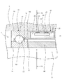
〔第3実施形態〕
図6は、本発明の第3実施形態の軸受装置201を回転軸を含む面で切った概略断面図である。この図6において、図1の第1実施形態の構成部と同一の構成部には、図1の第1実施形態の構成部の参照番号と同一の参照番号を付している。
[Third Embodiment]
FIG. 6 is a schematic cross-sectional view of the
上記軸受装置201は、単列アンギュラ玉軸受11内にグリース21の油分を供給する液体潤滑剤供給装置212を具備する。
The
上記液体潤滑剤供給装置212は、工作機械のハウジング2の内周面に内嵌する環状の外側間座219と、外輪13の内周面と内輪14の外周面との間に連通する液体潤滑剤通路30と、外輪13の内周面と内輪14の外周面との間にグリース21の油分を供給するための加振装置224とを有する。液体潤滑剤供給装置212の径方向内側には、工作機械の主軸3の外周面に外嵌する環状の内側間座220が配置されている。
The liquid
上記外側間座219には、グリース21を貯留するグリース貯留部222が形成されている。このグリース貯留部222内の空間は液体潤滑剤通路30を介して外輪13の内周面と内輪14の外周面との間の空間と連通する。また、外側間座219の液体潤滑剤通路30近傍の部分には段付貫通穴251が設けられている。この段付貫通穴251に樹脂(例えばプラスチック)製の閉鎖部材252を取り付けて、グリース21が段付貫通穴251から漏れ出ないようにしている。なお、グリース貯留部222は非液体潤滑剤貯蔵部の一例である。
The
上記加振装置224は、金属製のリードバルブ241と、このリードバルブ241を振動させるための磁石部242とで構成されている。
The
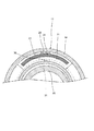
図7は、図6のF7−F7線から見た断面図である。なお、図7において、二点鎖線は外輪13の肩の内周面の位置を示し、点線は突出部31の形状を示している。
7 is a cross-sectional view taken along line F7-F7 in FIG. In FIG. 7, the two-dot chain line indicates the position of the inner peripheral surface of the shoulder of the
図6、図7に示すように、グリース貯留部222内の空間は、外輪13の軸線を含む断面において略矩形に形成されていると共に、外輪13の軸線に垂直な断面において略円弧状に形成されている。液体潤滑剤通路30は、上記第1,第2実施形態と同様に、突出部31と外輪13の肩で一部が形成され、外側間座219の外輪13側の端部に残りの部分が形成されている。
As shown in FIGS. 6 and 7, the space in the
上記リードバルブ241は、閉鎖部材252に対して傾斜するように、液体潤滑剤通路30に配置されている。このリードバルブ241の一方の端部は外側間座219に固定されているが、リードバルブ241の他方の端部は自由端部である(図4参照)。
The
上記磁石部242は、内側間座220の外周面部の一部を磁化することで形成されている。また、磁石部242は、径方向においてリードバルブ241および閉鎖部材252と重なるように形成されている。
The
上記構成の軸受装置201によれば、上記磁石部242が閉鎖部材252に対向すると、リードバルブ241の他方の端部(自由端部)が閉鎖部材252を介して磁石部242の磁力を受けて径方向内側に移動する。そして、上記磁石部242が閉鎖部材252に対向しなくなると、リードバルブ241の他方の端部が弾性により径方向外側に移動する。したがって、上記内側間座220が主軸3と共に回転することによって、磁石部242が閉鎖部材252と対向と非対向を繰り返すので、リードバルブ241の他方の端部が振動する。その結果、上記リードバルブ241の他方の端部の振動がグリース21に加わって、グリース21から基油が分離される。この基油は、液体潤滑剤通路30を通って、外輪13の内周面と内輪14の外周面との間に入り、外輪側軌道溝17の外側間座219側の部分に付着する。これにより、上記外輪側軌道溝17、内輪側軌道溝18および玉15が基油で潤滑される。
According to the
このように、上記基油の搬送に圧縮エアを用いないので、特開2002−130303号公報でのオイルの飛散は起こらず、工作機械を使用する環境が劣悪にならないようにすることができる。 Thus, since compressed air is not used for conveyance of the above-mentioned base oil, scattering of oil does not occur in JP-A-2002-130303, and the environment in which the machine tool is used can be prevented from being deteriorated.
また、上記外輪軌道溝17、内輪側軌道溝18および玉15を基油で潤滑するので、攪拌抵抗を小さくできて、寿命を長くでき、メンテナンスフリーとすることが可能である。
Further, since the outer
また、上記リードバルブ241の他方の端部の振動によって、グリース21からの基油の分離が促進されるので、外輪13の内周面と内輪14の外周面との間に入る基油の量を増やし、オイル潤滑と同等の性能の潤滑を行える。
Further, since the separation of the base oil from the
また、上記外側間座219に、グリース21を貯留するグリース貯留部222を形成しているので、グリース21の補充回数を減らし、メンテナンス性をさらに向上させることができる。
Moreover, since the
また、上記液体潤滑剤通路30のアンギュラ玉軸受11の端は外輪軌道溝17、内輪側軌道溝18および玉15の近傍に配置されているので、外輪軌道溝17、内輪側軌道溝18および玉15に基油を効率良く供給することができる。
Further, the end of the angular
また、上記グリース貯留部222内にリードバルブ241を配設すると共に、内側間座220の外周面部の一部を磁化して磁石部242を形成するので、液体潤滑剤供給装置212を小型化することができる。
In addition, the
また、上記加振装置224はリードバルブ241および磁石部242からなるので、上記第1,2実施形態のような電力供給を受けなくても、グリース21に振動を加えて、グリース21から基油を分離できる。
Further, since the
また、上記加振装置224はリードバルブ241および磁石部242からなるので、壊れ難く、保守が容易である。
Further, since the
上記第3実施形態では、軸受装置201は、単列アンギュラ玉軸受11を備えていたが、複列アンギュラ玉軸受を備えてもよいし、アンギュラ玉軸受以外の例えば円筒ころ軸受、円錐ころ軸受などを備えてもよい。
In the third embodiment, the
上記第3実施形態では、グリース21を用いていたが、グリース21でなくても、固体状、半固体状もしくは粘ちょう状の潤滑剤、または、潤滑剤含有樹脂組成物である非液体潤滑剤であれば用いてもよい。この潤滑剤含有樹脂組成物としては、例えば、PE(ポリエチレン)にオイルを加えて固形化したものがある。
In the third embodiment, the
上記第3実施形態では、外周面部に1つの磁石部242を有する内側間座220を用いていたが、外周面部に複数の磁石部を有する内側間座を用いてもよい。
In the third embodiment, the
上記第3実施形態では、磁石部242は、内側間座220の外周面部の一部を磁化したものであったが、内側間座の外周面に設けた凹部に嵌合させた磁石であってもよい。
In the said 3rd Embodiment, although the
上記第3実施形態では、グリース貯留部222内の空間は、外輪13の軸線に垂直な断面において略円弧状になっていたが、外輪13の軸線に垂直な断面において環状にしてもよい。
In the third embodiment, the space in the
上記第3実施形態では、外側間座219にグリース貯留部222を1つ形成していたが、外側間座19にグリース貯留部222を周方向に所定間隔を隔てて複数形成してもよい。つまり、本発明の一実施形態では、非液体潤滑剤貯蔵部の数は、単数でも複数でもよい。
In the third embodiment, one
上記第3実施形態では、1つのグリース貯留部222内の空間が、1つの液体潤滑剤通路30を介して外輪13の内周面と内輪14の外周面との間の空間と連通するようにしていたが、1つのグリース貯留部222内の空間が、複数の液体潤滑剤通路30を介して外輪13の内周面と内輪14の外周面との間の空間と連通するようにしてもよい。つまり、本発明の一実施形態では、1つの非液体潤滑剤貯蔵部に接続する液体潤滑剤通路の数は、単数でも複数でもよい。
In the third embodiment, the space in one
また、本発明の軸受装置は、工作機械以外の機械であっても使用でき、特に、高速回転する軸を有する機械に好適に使用できる。 Further, the bearing device of the present invention can be used even in a machine other than a machine tool, and can be suitably used for a machine having a shaft that rotates at a high speed.
1,201 軸受装置
12 液体潤滑剤供給装置
13 外輪
14 内輪
15 玉
16 保持器
17 外輪側軌道溝
18 内輪側軌道溝
21 グリース
22 グリース貯留部
24,224 加振装置
26 温度センサ
27,127 制御装置
28 回転速度センサ
30 液体潤滑剤通路
241 リリーフバルブ
242 磁石部
DESCRIPTION OF SYMBOLS 1,201
Claims (3)
外周面に軌道面を有する内輪と、
上記外輪の上記軌道面と上記内輪の上記軌道面との間に配置された複数の転動体と、
上記複数の転動体を保持する保持器と、
上記外輪の上記内周面と上記内輪の上記外周面との間に液体潤滑剤を供給する液体潤滑剤供給装置と
を備え、
上記液体潤滑剤供給装置は、
上記外輪の上記内周面と上記内輪の上記外周面との間に連通する液体潤滑剤通路と、
上記液体潤滑剤通路から上記外輪の上記内周面と上記内輪の上記外周面との間に上記液体潤滑剤を供給するために、固体状、半固体状もしくは粘ちょう状の潤滑剤、または、潤滑剤含有樹脂組成物である非液体潤滑剤に当接して、上記非液体潤滑剤に振動を加えることができる加振装置と
を有し、
上記外輪と上記内輪との少なくとも一方の温度を検出する温度センサと、
上記温度センサが検出した温度に基づいて、上記加振装置を制御する制御装置と
を備え、
上記制御装置は、上記温度センサが検出した温度が第1温度であるときにおける上記加振装置の振動時間、振動数または振幅が、上記温度センサが検出した温度が上記第1温度とは異なる第2温度であるときにおける上記加振装置の振動時間、振動数または振幅と異なるように制御することを特徴とする軸受装置。 An outer ring having a raceway surface on the inner peripheral surface;
An inner ring having a raceway surface on the outer peripheral surface;
A plurality of rolling elements disposed between the raceway surface of the outer ring and the raceway surface of the inner ring;
A cage for holding the plurality of rolling elements;
A liquid lubricant supply device for supplying a liquid lubricant between the inner peripheral surface of the outer ring and the outer peripheral surface of the inner ring;
The liquid lubricant supply device is
A liquid lubricant passage communicating between the inner peripheral surface of the outer ring and the outer peripheral surface of the inner ring;
In order to supply the liquid lubricant between the inner peripheral surface of the outer ring and the outer peripheral surface of the inner ring from the liquid lubricant passage, a solid, semi-solid or viscous lubricant, or the non-liquid lubricant is a lubricant-containing resin composition in contact, possess a vibrating can apply vibration to the non-liquid lubricant system,
A temperature sensor for detecting the temperature of at least one of the outer ring and the inner ring;
A control device for controlling the vibration exciter based on the temperature detected by the temperature sensor;
With
When the temperature detected by the temperature sensor is the first temperature, the control device has a vibration time, frequency or amplitude of the vibration exciter that is different from the first temperature. A bearing device that is controlled so as to be different from the vibration time, frequency, or amplitude of the vibration exciter when the temperature is two .
外周面に軌道面を有する内輪と、
上記外輪の上記軌道面と上記内輪の上記軌道面との間に配置された複数の転動体と、
上記複数の転動体を保持する保持器と、
上記外輪の上記内周面と上記内輪の上記外周面との間に液体潤滑剤を供給する液体潤滑剤供給装置と
を備え、
上記液体潤滑剤供給装置は、
上記外輪の上記内周面と上記内輪の上記外周面との間に連通する液体潤滑剤通路と、
上記液体潤滑剤通路から上記外輪の上記内周面と上記内輪の上記外周面との間に上記液体潤滑剤を供給するために、固体状、半固体状もしくは粘ちょう状の潤滑剤、または、潤滑剤含有樹脂組成物である非液体潤滑剤に当接して、上記非液体潤滑剤に振動を加えることができる加振装置と
を有し、
上記外輪または上記内輪の回転速度を検出する回転速度センサと、
上記回転速度センサが検出した回転速度に基づいて、上記加振装置を制御する制御装置と
を備え、
上記制御装置は、上記回転速度センサが検出した回転速度が第1回転速度における上記加振装置の振動時間、振動数または振幅が、上記回転速度センサが検出した回転速度が上記第1回転速度とは異なる第2回転速度における上記加振装置の振動時間、振動数または振幅と異なるように制御することを特徴とする軸受装置。 An outer ring having a raceway surface on the inner peripheral surface;
An inner ring having a raceway surface on the outer peripheral surface;
A plurality of rolling elements disposed between the raceway surface of the outer ring and the raceway surface of the inner ring;
A cage for holding the plurality of rolling elements;
A liquid lubricant supply device for supplying a liquid lubricant between the inner peripheral surface of the outer ring and the outer peripheral surface of the inner ring;
With
The liquid lubricant supply device is
A liquid lubricant passage communicating between the inner peripheral surface of the outer ring and the outer peripheral surface of the inner ring;
In order to supply the liquid lubricant between the inner peripheral surface of the outer ring and the outer peripheral surface of the inner ring from the liquid lubricant passage, a solid, semi-solid or viscous lubricant, or A vibration device capable of applying vibration to the non-liquid lubricant in contact with the non-liquid lubricant that is a lubricant-containing resin composition;
Have
A rotational speed sensor for detecting the rotational speed of the outer ring or the inner ring ;
A control device for controlling the excitation device based on the rotation speed detected by the rotation speed sensor;
The control device is configured such that the rotation time detected by the rotation speed sensor is the first rotation speed, the vibration time, the vibration frequency, or the amplitude of the vibration exciter is the first rotation speed. Is controlled so as to be different from the vibration time, vibration frequency or amplitude of the vibration exciter at different second rotational speeds.
上記液体潤滑剤供給装置は、上記非液体潤滑剤を貯蔵する非液体潤滑剤貯蔵部を有し、
この非液体潤滑剤貯蔵部内に上記加振装置を配設したことを特徴とする軸受装置。 The bearing device according to claim 1 or 2 ,
The liquid lubricant supply device has a non-liquid lubricant storage unit for storing the non-liquid lubricant,
A bearing device in which the vibration exciter is disposed in the non-liquid lubricant reservoir.
Priority Applications (3)
| Application Number | Priority Date | Filing Date | Title |
|---|---|---|---|
| JP2010217017A JP5561069B2 (en) | 2009-12-17 | 2010-09-28 | Bearing device |
| US12/965,088 US8851758B2 (en) | 2009-12-17 | 2010-12-10 | Bearing device |
| EP10195364.4A EP2336585B1 (en) | 2009-12-17 | 2010-12-16 | Bearing device |
Applications Claiming Priority (3)
| Application Number | Priority Date | Filing Date | Title |
|---|---|---|---|
| JP2009286542 | 2009-12-17 | ||
| JP2009286542 | 2009-12-17 | ||
| JP2010217017A JP5561069B2 (en) | 2009-12-17 | 2010-09-28 | Bearing device |
Publications (2)
| Publication Number | Publication Date |
|---|---|
| JP2011144921A JP2011144921A (en) | 2011-07-28 |
| JP5561069B2 true JP5561069B2 (en) | 2014-07-30 |
Family
ID=43754908
Family Applications (1)
| Application Number | Title | Priority Date | Filing Date |
|---|---|---|---|
| JP2010217017A Expired - Fee Related JP5561069B2 (en) | 2009-12-17 | 2010-09-28 | Bearing device |
Country Status (3)
| Country | Link |
|---|---|
| US (1) | US8851758B2 (en) |
| EP (1) | EP2336585B1 (en) |
| JP (1) | JP5561069B2 (en) |
Families Citing this family (9)
| Publication number | Priority date | Publication date | Assignee | Title |
|---|---|---|---|---|
| JP5774395B2 (en) * | 2011-07-13 | 2015-09-09 | Ntn株式会社 | Rolling bearing device |
| DE102014208597A1 (en) * | 2014-05-08 | 2015-04-16 | Schaeffler Technologies Gmbh & Co. Kg | roller bearing assembly |
| CN105020380A (en) * | 2015-06-19 | 2015-11-04 | 长兴万顺保温材料有限公司 | Transmission device for flour mill |
| JP6686473B2 (en) * | 2016-01-29 | 2020-04-22 | 株式会社ジェイテクト | Bearing device and method of supplying lubricating oil to bearing |
| JP7362239B2 (en) * | 2018-02-13 | 2023-10-17 | Ntn株式会社 | Bearing devices and spindle devices |
| CN111022510B (en) * | 2019-11-30 | 2020-11-24 | 乐清市凡山电器有限公司 | A smooth shock-absorbing bearing device for automobiles |
| DE102020204527A1 (en) * | 2020-04-08 | 2021-01-07 | Robert Bosch Gesellschaft mit beschränkter Haftung | Lubrication arrangement |
| CN114370456A (en) * | 2021-12-13 | 2022-04-19 | 上海航天控制技术研究所 | Microporous supplementary lubrication device for bearing with long space life |
| CN117091063B (en) * | 2023-10-18 | 2024-01-09 | 沈阳仪表科学研究院有限公司 | Bearing automatic lubrication regulation and control method, system and device |
Family Cites Families (23)
| Publication number | Priority date | Publication date | Assignee | Title |
|---|---|---|---|---|
| GB1116286A (en) | 1966-02-28 | 1968-06-06 | Stothert & Pitt Ltd | Lubrication device for use in a vibratory roller |
| DE2012292B2 (en) * | 1970-03-14 | 1972-07-06 | Wacker Werke KG, 8000 München | ARRANGEMENT OF A LUBRICANT STORAGE ROOM FOR INDOOR VIBRATORS |
| US3822002A (en) * | 1972-12-08 | 1974-07-02 | E Reedy | Uniblock lubricator |
| DE3823497A1 (en) | 1988-07-11 | 1990-01-18 | Siemens Ag | PIEZOELECTRIC LUBRICATION DEVICE FOR A BEARING |
| JPH07103228A (en) | 1993-10-06 | 1995-04-18 | Koyo Seiko Co Ltd | Spacer for rolling bearing |
| US6446682B1 (en) * | 1995-06-06 | 2002-09-10 | James P. Viken | Auto-loading fluid exchanger and method of use |
| JP4131312B2 (en) * | 2000-10-27 | 2008-08-13 | 日本精工株式会社 | Bearing device |
| JP2003090335A (en) * | 2000-12-01 | 2003-03-28 | Nsk Ltd | Rolling bearing device with sensor and rotation support device with sensor |
| JP2002213687A (en) * | 2001-01-18 | 2002-07-31 | Okuma Corp | Bearing lubricating device |
| JP4151472B2 (en) * | 2003-04-25 | 2008-09-17 | 株式会社ジェイテクト | Roller bearing device and lubrication method for roller bearing |
| JP3929440B2 (en) * | 2003-12-25 | 2007-06-13 | ファナック株式会社 | Electric motor |
| KR20070083655A (en) * | 2004-10-08 | 2007-08-24 | 엔티엔 가부시키가이샤 | Rolling bearing |
| JP4234127B2 (en) | 2004-10-08 | 2009-03-04 | Ntn株式会社 | Rolling bearing |
| JP2006112457A (en) * | 2004-10-12 | 2006-04-27 | Nsk Ltd | Water pump bearing |
| JP2006226311A (en) * | 2005-02-15 | 2006-08-31 | Jtekt Corp | Rolling bearing device |
| JP2007064139A (en) * | 2005-09-01 | 2007-03-15 | Shimadzu Corp | High speed rotating device |
| JP4424293B2 (en) | 2005-09-29 | 2010-03-03 | 株式会社ジェイテクト | Rolling bearing device |
| JP2007224934A (en) * | 2006-02-21 | 2007-09-06 | Ntn Corp | Rolling bearing |
| JP2008014411A (en) * | 2006-07-06 | 2008-01-24 | Jtekt Corp | Rolling bearing lubrication structure |
| JP2009068511A (en) * | 2007-09-10 | 2009-04-02 | Toshiba Corp | Two-part sliding bearing device and rotating machine |
| DE102007049674A1 (en) | 2007-10-17 | 2009-04-23 | Schaeffler Kg | Method and arrangement for supplying a bearing area with a lubricant, in particular for supplying a rolling bearing with lubricant |
| EP2306037B1 (en) * | 2008-07-25 | 2018-05-16 | JTEKT Corporation | Roller bearing device, and method for forming lubrication means for the device |
| US8083469B1 (en) * | 2009-03-20 | 2011-12-27 | Florida Turbine Technologies, Inc. | High temperature bearing with lubricant |
-
2010
- 2010-09-28 JP JP2010217017A patent/JP5561069B2/en not_active Expired - Fee Related
- 2010-12-10 US US12/965,088 patent/US8851758B2/en not_active Expired - Fee Related
- 2010-12-16 EP EP10195364.4A patent/EP2336585B1/en not_active Not-in-force
Also Published As
| Publication number | Publication date |
|---|---|
| US20110150379A1 (en) | 2011-06-23 |
| EP2336585A1 (en) | 2011-06-22 |
| JP2011144921A (en) | 2011-07-28 |
| EP2336585B1 (en) | 2013-04-17 |
| US8851758B2 (en) | 2014-10-07 |
Similar Documents
| Publication | Publication Date | Title |
|---|---|---|
| JP5561069B2 (en) | Bearing device | |
| JP5633185B2 (en) | Rolling bearing | |
| JP5549587B2 (en) | Rolling bearing device and method for forming lubricating means thereof | |
| US20120301065A1 (en) | Rolling bearing lubrication structure and rolling bearing | |
| JP5948919B2 (en) | Ball bearing, motor and spindle device using the same | |
| WO2012148899A1 (en) | Bearing and lubrication system used therewith | |
| JP2010019268A (en) | Rolling bearing device | |
| JP5845652B2 (en) | Bearing device and spindle device for machine tool | |
| JP5982881B2 (en) | Ball bearing, motor and spindle device using the same | |
| JP2009162341A (en) | Rolling bearing | |
| JP2015197196A (en) | Roller bearing cage | |
| JP4256391B2 (en) | Rolling bearing | |
| JP2005180629A (en) | Rolling bearing | |
| JP4732301B2 (en) | Rolling bearing | |
| JP2006046454A (en) | Bearing device, spindle device and machine tool | |
| JP2008202798A (en) | Rolling bearing device | |
| JP3736628B2 (en) | Bearing device for supporting spindle of machine tool | |
| JP2011058520A (en) | Rolling bearing device | |
| JP2001099166A (en) | Bearing lubrication device and bearing | |
| JP2006226427A (en) | Rolling bearing | |
| JP2006234072A (en) | Rolling bearing | |
| JP2015113956A (en) | Bearing device and spindle device | |
| JP4225104B2 (en) | Rolling bearing device | |
| JP2009192056A (en) | Rolling bearing | |
| JP2012037046A (en) | Rolling bearing |
Legal Events
| Date | Code | Title | Description |
|---|---|---|---|
| A621 | Written request for application examination |
Free format text: JAPANESE INTERMEDIATE CODE: A621 Effective date: 20130821 |
|
| A977 | Report on retrieval |
Free format text: JAPANESE INTERMEDIATE CODE: A971007 Effective date: 20140205 |
|
| A131 | Notification of reasons for refusal |
Free format text: JAPANESE INTERMEDIATE CODE: A131 Effective date: 20140212 |
|
| A521 | Written amendment |
Free format text: JAPANESE INTERMEDIATE CODE: A523 Effective date: 20140328 |
|
| TRDD | Decision of grant or rejection written | ||
| A01 | Written decision to grant a patent or to grant a registration (utility model) |
Free format text: JAPANESE INTERMEDIATE CODE: A01 Effective date: 20140513 |
|
| A61 | First payment of annual fees (during grant procedure) |
Free format text: JAPANESE INTERMEDIATE CODE: A61 Effective date: 20140526 |
|
| R150 | Certificate of patent or registration of utility model |
Ref document number: 5561069 Country of ref document: JP Free format text: JAPANESE INTERMEDIATE CODE: R150 |
|
| LAPS | Cancellation because of no payment of annual fees |