EP1470262B1 - Verfahren zur herstellung von metallschaum und eine vorrichtung zu deren durchführung - Google Patents
Verfahren zur herstellung von metallschaum und eine vorrichtung zu deren durchführung Download PDFInfo
- Publication number
- EP1470262B1 EP1470262B1 EP03701379A EP03701379A EP1470262B1 EP 1470262 B1 EP1470262 B1 EP 1470262B1 EP 03701379 A EP03701379 A EP 03701379A EP 03701379 A EP03701379 A EP 03701379A EP 1470262 B1 EP1470262 B1 EP 1470262B1
- Authority
- EP
- European Patent Office
- Prior art keywords
- foam
- mould
- sample
- transfer container
- molten metal
- Prior art date
- Legal status (The legal status is an assumption and is not a legal conclusion. Google has not performed a legal analysis and makes no representation as to the accuracy of the status listed.)
- Expired - Lifetime
Links
- 238000000034 method Methods 0.000 title claims abstract description 30
- 239000006262 metallic foam Substances 0.000 title claims abstract description 17
- 238000005266 casting Methods 0.000 title claims abstract description 11
- 239000006260 foam Substances 0.000 claims abstract description 103
- 239000002184 metal Substances 0.000 claims abstract description 42
- 229910052751 metal Inorganic materials 0.000 claims abstract description 42
- 238000005187 foaming Methods 0.000 claims description 19
- 239000000463 material Substances 0.000 claims description 12
- 238000001816 cooling Methods 0.000 claims description 5
- 238000009966 trimming Methods 0.000 claims description 5
- 239000004088 foaming agent Substances 0.000 claims description 4
- 229910052782 aluminium Inorganic materials 0.000 claims description 2
- XAGFODPZIPBFFR-UHFFFAOYSA-N aluminium Chemical compound [Al] XAGFODPZIPBFFR-UHFFFAOYSA-N 0.000 claims description 2
- 238000000151 deposition Methods 0.000 claims 3
- 230000000295 complement effect Effects 0.000 claims 1
- 238000007599 discharging Methods 0.000 claims 1
- 239000012530 fluid Substances 0.000 claims 1
- 239000000126 substance Substances 0.000 claims 1
- 230000032258 transport Effects 0.000 abstract 1
- 230000008569 process Effects 0.000 description 11
- 239000004576 sand Substances 0.000 description 9
- 229910000831 Steel Inorganic materials 0.000 description 4
- 210000004027 cell Anatomy 0.000 description 4
- 238000004519 manufacturing process Methods 0.000 description 4
- 239000010959 steel Substances 0.000 description 4
- 239000000654 additive Substances 0.000 description 3
- 230000008901 benefit Effects 0.000 description 3
- 239000000843 powder Substances 0.000 description 3
- 238000003825 pressing Methods 0.000 description 3
- 239000000047 product Substances 0.000 description 3
- 230000009471 action Effects 0.000 description 2
- 230000015572 biosynthetic process Effects 0.000 description 2
- 238000010924 continuous production Methods 0.000 description 2
- 238000005520 cutting process Methods 0.000 description 2
- 239000012467 final product Substances 0.000 description 2
- 238000010438 heat treatment Methods 0.000 description 2
- 229910001338 liquidmetal Inorganic materials 0.000 description 2
- 239000000203 mixture Substances 0.000 description 2
- 230000000630 rising effect Effects 0.000 description 2
- OKTJSMMVPCPJKN-UHFFFAOYSA-N Carbon Chemical compound [C] OKTJSMMVPCPJKN-UHFFFAOYSA-N 0.000 description 1
- 230000005540 biological transmission Effects 0.000 description 1
- 239000000919 ceramic Substances 0.000 description 1
- 230000001419 dependent effect Effects 0.000 description 1
- 238000001704 evaporation Methods 0.000 description 1
- 230000008020 evaporation Effects 0.000 description 1
- 238000000605 extraction Methods 0.000 description 1
- 210000000497 foam cell Anatomy 0.000 description 1
- 239000006261 foam material Substances 0.000 description 1
- 229910002804 graphite Inorganic materials 0.000 description 1
- 239000010439 graphite Substances 0.000 description 1
- 238000002347 injection Methods 0.000 description 1
- 239000007924 injection Substances 0.000 description 1
- 239000007788 liquid Substances 0.000 description 1
- 230000007246 mechanism Effects 0.000 description 1
- 238000002844 melting Methods 0.000 description 1
- 230000008018 melting Effects 0.000 description 1
- 238000012986 modification Methods 0.000 description 1
- 230000004048 modification Effects 0.000 description 1
- 230000002028 premature Effects 0.000 description 1
- 239000011819 refractory material Substances 0.000 description 1
- 238000007790 scraping Methods 0.000 description 1
- 238000000926 separation method Methods 0.000 description 1
- 230000035939 shock Effects 0.000 description 1
- 239000007787 solid Substances 0.000 description 1
- 238000009987 spinning Methods 0.000 description 1
Images

Classifications
-
- B—PERFORMING OPERATIONS; TRANSPORTING
- B22—CASTING; POWDER METALLURGY
- B22D—CASTING OF METALS; CASTING OF OTHER SUBSTANCES BY THE SAME PROCESSES OR DEVICES
- B22D25/00—Special casting characterised by the nature of the product
- B22D25/005—Casting metal foams
-
- B—PERFORMING OPERATIONS; TRANSPORTING
- B22—CASTING; POWDER METALLURGY
- B22D—CASTING OF METALS; CASTING OF OTHER SUBSTANCES BY THE SAME PROCESSES OR DEVICES
- B22D27/00—Treating the metal in the mould while it is molten or ductile ; Pressure or vacuum casting
-
- C—CHEMISTRY; METALLURGY
- C22—METALLURGY; FERROUS OR NON-FERROUS ALLOYS; TREATMENT OF ALLOYS OR NON-FERROUS METALS
- C22C—ALLOYS
- C22C1/00—Making non-ferrous alloys
- C22C1/02—Making non-ferrous alloys by melting
-
- C—CHEMISTRY; METALLURGY
- C22—METALLURGY; FERROUS OR NON-FERROUS ALLOYS; TREATMENT OF ALLOYS OR NON-FERROUS METALS
- C22C—ALLOYS
- C22C1/00—Making non-ferrous alloys
- C22C1/02—Making non-ferrous alloys by melting
- C22C1/026—Alloys based on aluminium
-
- C—CHEMISTRY; METALLURGY
- C22—METALLURGY; FERROUS OR NON-FERROUS ALLOYS; TREATMENT OF ALLOYS OR NON-FERROUS METALS
- C22C—ALLOYS
- C22C1/00—Making non-ferrous alloys
- C22C1/08—Alloys with open or closed pores
-
- C—CHEMISTRY; METALLURGY
- C22—METALLURGY; FERROUS OR NON-FERROUS ALLOYS; TREATMENT OF ALLOYS OR NON-FERROUS METALS
- C22C—ALLOYS
- C22C1/00—Making non-ferrous alloys
- C22C1/08—Alloys with open or closed pores
- C22C1/083—Foaming process in molten metal other than by powder metallurgy
- C22C1/086—Gas foaming process
-
- C—CHEMISTRY; METALLURGY
- C22—METALLURGY; FERROUS OR NON-FERROUS ALLOYS; TREATMENT OF ALLOYS OR NON-FERROUS METALS
- C22C—ALLOYS
- C22C1/00—Making non-ferrous alloys
- C22C1/08—Alloys with open or closed pores
- C22C1/083—Foaming process in molten metal other than by powder metallurgy
Definitions
- the present invention is directed to an apparatus and a method for casting metal foam objects.
- a metal foam is generally created by generating a gas in a molten metal bath so as to form a molten metal foam. The foam is then extracted and cooled.
- Metal foam offers various advantages as a replacement to standard metal such as meeting the above mentioned high strength to weight ratio, high shock or impact absorbing qualities, and sound absorbing qualities.
- the prior art teaches various methods for producing metal foam such as in US Patent numbers 5,221,324 and 5,622,542.
- the known methods of generating the gas mentioned above include, among others: (1) the use of a gas supply, which blows or injects the gas into the molten metal; (2) the use of gas generating, or foaming agents, which release gas when heated; and, (3) the use of impellers to draw the desired gas into the molten metal bath. It is also know in the art to provide the molten metal with a number of additives to assist the foam in maintaining the integrity of the formed cells.
- the process taught by this prior art method includes various disadvantages. Firstly, the process must be carried out in a batch manner. That is, the production of a single piece involves each of the steps of charging the chamber with the required powders, melting the powders, forcing the material into the mould, finally, completing the foaming process, cooling the mould and extracting the finished article. For this reason, the process taught in patent number 5,865,237 is very time consuming. Further, the step of forcing the foaming material into a mould cavity would require a force to be applied against the foam cells. This force would inevitably result in damage to some of the cells and, therefore, reduce some of the advantage of the foam material. In addition, the patent requires the use of a piston to force the foaming material into the mould.
- the present invention seeks to provide a metal foam casting apparatus and process that mitigates at least some of the disadvantages of methods known in the art.
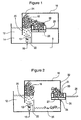
- the apparatus includes a heated chamber 10 that is connected to a molten metal bath 12 in which is contained a molten metal 14.
- the bath 12 is maintained at a temperature sufficient to maintain the metal in a molten state using any known type of heating apparatus.
- a gas inlet or injection port 16 is provided at the bottom of the bath 12, through which is pumped a gas 13.
- the gas 13 is bubbled through the molten metal 14 thereby causing the formation of a foam 18 from the molten metal 14.
- the gas port 16 may include a porous nozzle which is permeable to the gas.
- the port may comprise any other known structure for allowing the gas to be bubbled through the molten metal. As is known in the art, the rising gas bubbles cause a foam 18 to form on the top surface of the molten metal 14.
- the bath 12 is divided into two sections by means of a dividing wall 20, thereby creating a foam forming section 22 of the bath.
- the gas port 16 is preferably positioned under the foam forming section 22 so as to cause the foam 18 to form in section 22. It will be appreciated that the foam formation will preferentially occur in section 22 due to the generally vertical rise of the gas bubbles 13. In order to ensure this, dividing wall 20 is partially submerged in the molten metal 14.
- Dividing wall 20 includes a curved diverter 24, which is one example of a means for directing the rising foam 18 towards the heated chamber 10.
- a foam transfer container or ladle 26 is provided within the chamber 10.
- the ladle 26 is connected to a reciprocating rod 28, which causes the ladle to move laterally within the chamber 10. It will be understood that any other means for moving the ladle 26 may be used.
- the ladle 26 is first positioned proximal to a side wall of the bath 12. Further, the ladle 26 is provided within the chamber 10 so that the opening 30 of the ladle 26 is generally at the same level as the side wall of the bath 12. Such vertical positioning is provided to enable the foam 18 directed by the diverter 24 to enter into and fill the ladle 26.
- the ladle 26 can be positioned slightly above the bath 12 or a further diverter mechanism can be utilized to cause foam to fill the ladle 26.
- the foam 18 can be scooped or otherwise provided into the ladle.
- the diverter 24 can be of any shape or orientation for serving the purpose mentioned above.
- FIG 2 illustrates the system of the invention with the ladle 26 withdrawn.
- a side wall 32, opposite the bath 12, of the heated chamber 10 is provided with a closable opening 34 through which the ladle 26 can be passed.
- the opening 34 is preferably maintained in a closed position, as shown in Figure 1, until the ladle 26 is to pass through, as shown in Figure 2. In this manner, heat loss from the chamber 10 is minimized.
- the opening 34 may also be kept open and other means utilized to maintain the temperature within the chamber 10.
- the opening 34 is dimensioned so as to minimize clearance of the ladle 26.
- the upper end 31 of the opening serves to scrape off any foam that exceeds the height of the ladle opening 30.
- the volume of the foam sample 27 withdrawn by the ladle 27 is consistent from one extraction to another. Furthermore, by using such a scraping action and not compacting the foam into the ladle, the integrity of the cells forming the foam is maintained.
- the purpose maintaining the chamber 10 in a heated state is to ensure that the foam 18 is not allowed to cool and solidify until the forming stage is complete (as will be described further below).
- the chamber 10 is maintained at a temperature of approximately 500 - 700 °C.
- Figure 2 also illustrates a pool 36 of molten metal and foam that spills from the bath 12, which collects at the bottom of the chamber 10. It will be appreciated that such spillage may be recycled back to the bath 12.
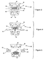
- Figure 3 illustrates the ladle completely withdrawn from the chamber 10 and positioned two halves of a mould 39.
- the mould 39 includes a first half 38 and a second half 40.
- Each half of the mould 39 is provided with a cavity, 42 and 44 respectively, which together form a mould cavity that conforms to the outer shape of the article to be formed.
- Each of the cavities 42 and 44 are also provided with a partial notch 45.
- the notches 45 combine to form an overflow space around the article. This will be described further below.
- the contents of the ladle must then be poured into one of the cavities in the mould halves.
- the mould halves are provided below and above the ladle so that the ladle need simply be emptied into the lower mould cavity.
- Figures 3 to 5 illustrate a preferred embodiment of the ladle 26 which is designed to facilitate the emptying of the foam sample 27 into the mould cavity.
- the ladle is formed in four sections, two pieces forming the base, 46 and 48, and two pieces forming the sides, 50 and 52. When the pieces 46, 48, 50 and 52 are connected together, they form the complete ladle as shown in Figure 3.
- the ladle 26 is dismantled by disconnecting the various pieces.
- the dismantling process begins with the base pieces 46 and 48 first being separated, by sliding them away from each other, followed by separation of the side pieces 50 and 52 in a similar manner. The initial removal of the base pieces ensures that the foam sample 27 is maintained in the desired size for pouring into the mould cavity.
- Figure 6 illustrates the mould 39 in a closed position, enclosing the foam sample 27 within the mould cavity.
- the notches 45 described above, combine to form an overflow space 54 into which flows any excess foam that exceeds the volume capacity of the mould cavity. After the mould is cooled, the formed metal foam article can be removed.
- the mould 39 is formed of sand as is commonly known in the art.
- Sand offers various advantages when forming moulds, including low material and mould manufacturing cost and also very low heat transmission. With regard to the latter aspect, as a poor heat transmitter, sand would allow the foam within the mould to remain at its near molten state temperature.
- the sand mould can be replaced with a steel mould as well. Such steel moulds would require heating as is known in the art to prevent premature cooling and hardening of the foam. Methods for using steel moulds are taught, for example, in US Patent number 5,865,237
- the foam should be maintained at a molten temperature in order to keep the foam in a formable molten state.
- cooling of the molten foam is prevented by rapidly transferring the foam sample to the mould and completing the casting process. Such rapid transfer avoids the need for any external heat requirements.
- the mould is preferably made of sand held together with moisture, any external heat would lead to lead to evaporation of the moisture and collapse of the mould.
- the region where the ladle is moved may be heated in a manner similar to the chamber 10 so as to prevent the foam sample from cooling.
- the mould itself would not be heated for the reasons mentioned above.
- metal moulds it will be appreciated that the entire region of passage of the ladle and the mould itself can be heated to the desired temperature. In such case, the mould can be cooled after closure to enable hardening of the cast foam.
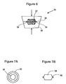
- Figure 7 A and B illustrate a top and side view, respectively, of a foam article 58 removed from the mould of Figure 6.
- the article 58 includes a ring 60 comprising the excess foam that was contained in the overflow space 54.
- Figure 8 shows a trim or nipping press 62 for removing the ring 60 on the formed article.
- the press 62 includes a base 64 for supporting the article 58, having a first blade 66.
- the article is positioned on the base 64 so that the ring 60 rests on the first blade 66.
- the press also includes a pressing portion 68, having a second blade 70, which cooperates with first blade 66 to form a nip.
- the base 64 and pressing portion 68 are both provided with a cavity between their respective blades to accommodate the article 58.
- the article 58 is positioned on the base 64 as indicated previously.
- the pressing portion 68 is then moved towards the base 64 so that the two blades are brought into contact. In this manner, the ring 60, is nipped or trimmed off the article 58 by the cutting action of the cooperating blades 66 and 70.
- Figure 9 A and B illustrate the article after the trimming process.
- the foaming process has been described as using a gas supply port in the molten metal bath.
- any other foaming process may be used.
- a metal foam may be generated using foaming agents in a molten metal instead of a gas supply means.
- the molten metal may be supplied with various additives that are know to stabilize the foam formed there from.
- an impeller may be provided in the bath 12, which draws air into the molten metal.
- the gas port 16 of the invention may also comprise a rotating impeller or a vibrating nozzle.
- the present invention can be used to form articles from metal foams of varying densities.
- the density of the foam (which is a function of the size and wall thickness of the cells forming the foam) will depend on a variety of factors such as the speed of gas addition, the amount and type of foaming additives added to the molten metal.
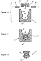
- a mould is shown generally at 74.
- the mould 74 includes a die region 76, which conforms to the shape of the final object to be formed and a funnel region or riser 80.
- the funnel region 80 serves to guide the foam 27 from the ladle 26.
- the ladle 26 is preferably in four sections as described above, namely, side walls 50 and 52 and a base formed of pieces 46 and 48.
- the base pieces 46 and 48 are shown in the separated position, which allows the foam 27 to drop into the mould.
- the interior wall 82 of the funnel region 80 of the mould 74 directs the foam into the die region 76.
- the mould 74 may be formed with steel, ceramic, graphite, sand or other materials.
- a plunger (not shown) may be used to force the foam 27 into the die region 76. It will be understood that such plunger will conform to the dimensions of the funnel region 80.
- the plunger can be made of refractory materials.
- the mould 74 can be vibrated to force the foam 27 into the die region 76.
- the foam can be forced into the die region using a vacuum, by applying air pressure, or by spinning the mould. Various other means will be apparent to persons skilled in the art.
- Figure 11 illustrates the mould 74 after the foam has been delivered into the die region 76.
- the ladle is not shown in this figure.
- the mould of this embodiment does not need to be closed to form the final product.
- the mould is separable so as to enable removal of the formed product.
- the proportion of the funnel region has been exaggerated in order to depict the features of the mould and that the actual proportions and dimensions will be dependent on the final product being formed and will be easily determined by persons skilled in the art.
- Figure 12 illustrates an article 84 formed in the mould of Figures 10 and 11.
- a portion 86 of the formed article 84 may conform to the lower portion of the funnel region 80 of the mould 74.
- this portion 86 of the article can be easily trimmed by cutting or other means resulting in the final desired article 87, the outer shape of which corresponds to the shape of the die region or cavity 76. Again, the proportion of the trimmed portion 86 has been exaggerated in order to illustrate this embodiment.
- the die region 76 of the mould 74 is provided with a vent or well 88 for collecting any liquid metal that was not foamed.
- Figure 11 illustrated the well 88 wherein liquid, non-foam metal is collected.
- Figure 12 illustrates a solid metal piece 90, which corresponds to the molten metal that collects in the well 88. As will be understood, such extraneous piece 90 is easily cut off from the desired finished article.
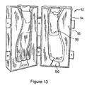
- Figure 13 illustrates a mould 92 in the open position, after forming the desired article.
- the mould comprises a metal casing 94 the inside of which is filled with sand 96.
- the interior portion of the mould includes a die cavity 98 formed into the sand.
- the upper end of the mould is provided with a funnel or guide as described above but not shown in Figure 13.
- the lower end of the mould includes a well 100 as described above.
- the well as shown is of a "dove tail" shape.
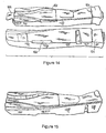
- Figure 14 illustrates an article 102 formed in the mould of Figure 13 prior to finishing.
- the article 102 includes a first end 104 that corresponds to the shape of a portion of the funnel (described above).
- a second end 106 corresponds to the liquid metal that entered the well 100.
- Figure 15 illustrates the article 102 of Figure 14 after trimming of the first and second ends.
- the present invention provides a casting process that does not require the foam generation step from being halted as with the prior art.
- the invention allows for a continuous process for generating foam, portions of which can be withdrawn and cast in a mould.
- the apparatus can be provided with multiple ladles each drawing samples from the same chamber but at sequential times. Such ladles would then deposit the respective samples to different moulds. In this manner, the invention provides for a continuous process for casting metal foam articles.
- the metal is aluminum. However, it will be appreciated that any other metal may be utilized in the invention.
Landscapes
- Chemical & Material Sciences (AREA)
- Engineering & Computer Science (AREA)
- Mechanical Engineering (AREA)
- Materials Engineering (AREA)
- Metallurgy (AREA)
- Organic Chemistry (AREA)
- Investigating And Analyzing Materials By Characteristic Methods (AREA)
- Molds, Cores, And Manufacturing Methods Thereof (AREA)
- Manufacture Of Porous Articles, And Recovery And Treatment Of Waste Products (AREA)
- Manufacture And Refinement Of Metals (AREA)
- Sampling And Sample Adjustment (AREA)
Claims (21)
- Vorrichtung zum Gießen eines Gegenstands aus Metallschaum umfassend,ein Bad für eine Metallschmelze, welches geschmolzenes Metall enthält;ein Mittel zur Erzeugung von Metallschaum, der in dem geschmolzenen Metall bereitgestellt wird;wobei das Mittel zur Erzeugung eines Schaums in einer Schäumungskammer in fluider Verbindung mit dem Bad bereitgestellt wird;ein Schaumtransferbehälter zur Aufnahme einer Probe des durch das Mittel zur Schäumung erzeugten Schaums, wobei der Behälter geeignet ist zwischen dem Innenraum und der Außenseite der Schäumungskammer hin und her bewegt zu werden;ein Mittel zum Entnehmen des Schaumtransferbehälters aus der Schäumungskammer undeine Gussform mit einem Formenhohlraum, der eine Form, welche zu dem Gegenstand komplementär ist, aufweist, wobei die Formenhöhlung zur Aufnahme der Schaumprobe aus dem Schaumtransferbehälter geeignet ist.
- Vorrichtung gemäß Anspruch 1, worin die Kammer beheizt ist, um den Schaum in einem geschmolzenen Schaumzustand zu halten.
- Vorrichtung gemäß Anspruch 2, worin das Metall Aluminium ist und die Kammer bei einer Temperatur von etwa 500 bis 700 °C gehalten wird.
- Vorrichtung gemäß Anspruch 1, worin die Kammer eine Öffnung umfasst, um eine Passage des Schaumtransferbehälters zu ermöglichen.
- Vorrichtung gemäß Anspruch 1 ferner umfassend ein Mittel zur Dosierung, um ein zuvor festgelegtes Volumen der Schaumprobe im Schaumtransferbehälter bereitzustellen.
- Vorrichtung gemäß Anspruch 1, worin das Mittel zur Erzeugung eines Schaums einen Gaseinlasskanal umfasst.
- Vorrichtung gemäß Anspruch 6, worin das Mittel zur Erzeugung eines Schaums eine gasdurchlässige Düse, die mit eines Gasquelle verbunden ist, umfasst.
- Vorrichtung gemäß Anspruch 6, worin das Mittel zur Erzeugung eines Schaums ein rotierendes Laufrad umfasst, das Auslässe zum Einleiten des Gases als Blasen in den geschmolzenen Metallschaum aus einer Gasquelle aufweist.
- Vorrichtung gemäß Anspruch 1, worin das Mittel zur Erzeugung eines Schaums einen hitzeaktivierten chemischen Schaumbildner, der im geschmolzenen Metall gelöst ist, umfasst.
- Vorrichtung gemäß Anspruch 1, worin das Mittel zur Erzeugung eines Schaums ein rotierendes Laufrad zum Tiefziehen von Luft in das geschmolzene Metall aufweist.
- Vorrichtung gemäß Anspruch 1 ferner umfassend ein Mittel zur Extraktion des im Schaumtransferbehälter enthaltenen Schaums.
- Vorrichtung gemäß Anspruch 1 ferner umfassend ein Mittel zur Leitung der Schaumprobe in den Schaumtransferbehälter.
- Verfahren zum Giessen eines Gegenstands aus einem Metallschaum umfassendBereitstellen eines geschmolzenen Metalls in einem Bad für geschmolzenes Metall;Erzeugung eines Schaums aus dem geschmolzenen Metall in einer Schäumungskammer;Aufnehmen einer Probe aus dem Schaum in einem Schaumtransferbehälter, wobei der Schaumtransferbehälter geeignet ist zwischen dem Innenraum und dem Äußeren der Schäumungskammer hin und her bewegt zu werden;Entnehmen des die Schaumprobe enthaltenden Schaumtransferbehälters aus der Schäumungskammer;Transportieren der Schaumprobe zu einer Gussform;Absetzen der Schaumprobe in der Gussform,Kühlen der Gussform undEntnehmen des geformten Gegenstands.
- Verfahren gemäß Anspruch 13, worin der Schaumtransferbehälter ein Gießtiegel ist.
- Verfahren gemäß Anspruch 13, worin die Probe ein vorher festgelegtes Volumen aufweist.
- Verfahren gemäß Anspruch 15, worin das vorher festgelegte Volumen der Probe durch Abmessen der Schaummenge, die zu der Gussform transportiert wird, erreicht wird.
- Verfahren gemäß Anspruch 13 ferner umfassend das Beschneiden des geformten Gegenstands, um überschüssiges Material zu entfernen.
- Vorrichtung gemäß Anspruch 1, worin der Schaumtransferbehälter eine Grundfläche, die zwischen einer offenen und einer geschlossenen Einstellung betriebsfähig ist, umfasst und worin der Transfer des Schaums in die Gussform durch Öffnen dieser Grundfläche erreicht wird.
- Vorrichtung gemäß Anspruch 1, worin die Gussform außerhalb der Schaumkammer angeordnet ist.
- Verfahren gemäß Anspruch 13, worin das Absetzen von Schaum das Positionieren des Schaumtransfer-Behälters über der Gussform und Fallenlassen des Schaums in die Gussform umfasst.
- Verfahren gemäß Anspruch 13, worin das Absetzen des Schaums ein Treiben des Schaums aus dem Schaumtransferbehälter umfasst.
Applications Claiming Priority (3)
| Application Number | Priority Date | Filing Date | Title |
|---|---|---|---|
| US35287402P | 2002-02-01 | 2002-02-01 | |
| US352874P | 2002-02-01 | ||
| PCT/CA2003/000117 WO2003064711A1 (en) | 2002-02-01 | 2003-01-31 | Metal foam casting apparatus and method |
Publications (2)
| Publication Number | Publication Date |
|---|---|
| EP1470262A1 EP1470262A1 (de) | 2004-10-27 |
| EP1470262B1 true EP1470262B1 (de) | 2005-10-19 |
Family
ID=27663145
Family Applications (1)
| Application Number | Title | Priority Date | Filing Date |
|---|---|---|---|
| EP03701379A Expired - Lifetime EP1470262B1 (de) | 2002-02-01 | 2003-01-31 | Verfahren zur herstellung von metallschaum und eine vorrichtung zu deren durchführung |
Country Status (11)
| Country | Link |
|---|---|
| US (1) | US6998535B2 (de) |
| EP (1) | EP1470262B1 (de) |
| JP (1) | JP2005515902A (de) |
| KR (1) | KR20040075964A (de) |
| CN (1) | CN1639364A (de) |
| AT (1) | ATE307218T1 (de) |
| BR (1) | BR0307407A (de) |
| CA (1) | CA2474949A1 (de) |
| DE (1) | DE60301947T2 (de) |
| MX (1) | MXPA04007455A (de) |
| WO (1) | WO2003064711A1 (de) |
Families Citing this family (19)
| Publication number | Priority date | Publication date | Assignee | Title |
|---|---|---|---|---|
| JP4014549B2 (ja) * | 2003-09-18 | 2007-11-28 | 富士電機システムズ株式会社 | ヒートシンク及びその製造方法 |
| CN100389371C (zh) * | 2004-09-16 | 2008-05-21 | 中芯国际集成电路制造(上海)有限公司 | 具有低待机电流的调压器用器件和方法 |
| AT503824B1 (de) * | 2006-07-13 | 2009-07-15 | Huette Klein Reichenbach Gmbh | Metallformkörper und verfahren zu dessen herstellung |
| AT504305B1 (de) * | 2006-10-05 | 2009-09-15 | H Tte Klein Reichenbach Ges M | Mehrschichtiger metallformkírper mit einer metallschaummatrix und dessen verwendung |
| US7699092B2 (en) * | 2007-06-18 | 2010-04-20 | Husky Injection Molding Systems Ltd. | Metal-molding system and process for making foamed alloy |
| CN101450377B (zh) * | 2007-11-28 | 2010-10-13 | 嘉兴中科金嘉特种材料有限公司 | 一种制造多孔材料的设备 |
| HU227545B1 (en) * | 2008-12-04 | 2011-08-29 | Bay Zoltan Alkalmazott Kutatasi Koezalapitvany | Method for producing metal foam |
| US20110239890A1 (en) * | 2010-04-06 | 2011-10-06 | Spritzer Michael H | Thermite-Metal Foam |
| CN101818279B (zh) * | 2010-05-14 | 2011-05-11 | 大连海事大学 | 一种用金属液发泡法制备多孔泡沫金属的设备及其方法 |
| WO2013144881A2 (pt) | 2012-03-27 | 2013-10-03 | Universidade Do Minho | Estrutura metálica leve e respectivo método de produção |
| EP3083105B1 (de) * | 2013-12-17 | 2017-11-15 | Taskin, Nilhan Urkmez | Kontinuierliche herstellung von verbundmetallschaum und verfahren und vorrichtung zum rühren eines partikelverstärkten verbundmetalls |
| US11021120B2 (en) | 2014-11-24 | 2021-06-01 | Tesseract Structural Innovations, Inc. | Uniform deceleration unit |
| EP3224035B1 (de) | 2014-11-24 | 2021-03-31 | Tesseract Structural Innovations Inc. | Gleichmässige entschleunigungseinheit |
| US11097782B2 (en) | 2014-11-24 | 2021-08-24 | Tesseract Structural Innovations, Inc. | Sill beam uniform deceleration unit |
| US9623480B2 (en) | 2014-12-19 | 2017-04-18 | Hathibelagal M. Roshan | Steel foam and method for manufacturing steel foam |
| US10493522B2 (en) | 2014-12-19 | 2019-12-03 | Maynard Steel Casting Company | Steel foam and method for manufacturing steel foam |
| JP2019514779A (ja) | 2016-04-21 | 2019-06-06 | テッサラクト ストラクチュラル イノベーションズ,インコーポレイテッド | 定減速ユニットクラッシュボックス |
| WO2019204350A1 (en) * | 2018-04-16 | 2019-10-24 | Tesseract Structural Innovations, Inc. | Uniform deceleration unit |
| CN115627377B (zh) * | 2022-10-24 | 2023-07-07 | 菏泽学院 | 一种异形泡沫金属制备装置及其实现方法 |
Family Cites Families (27)
| Publication number | Priority date | Publication date | Assignee | Title |
|---|---|---|---|---|
| DE1408468B2 (de) | 1959-01-05 | 1972-10-19 | Lor Corp., Enid, OkIa. (V.St.A.) | Verfahren zur herstellung von schaummetall in einem kontinuierlichen arbeitsgang |
| US3214265A (en) * | 1963-03-11 | 1965-10-26 | Lor Corp | Method of making metal foam bodies |
| US3300296A (en) * | 1963-07-31 | 1967-01-24 | American Can Co | Method of producing a lightweight foamed metal |
| US3329198A (en) * | 1964-09-29 | 1967-07-04 | Ilikon Corp | Method of blowing metal objects into mold with porous insert |
| GB1072869A (en) * | 1965-02-23 | 1967-06-21 | Edwards High Vacuum Int Ltd | Improvements in or relating to methods of and apparatus for stripping liquids |
| US3297431A (en) * | 1965-06-02 | 1967-01-10 | Standard Oil Co | Cellarized metal and method of producing same |
| US3367401A (en) * | 1966-06-15 | 1968-02-06 | Ilikon Corp | Apparatus for blowing hollow metal articles |
| US3843353A (en) * | 1969-02-19 | 1974-10-22 | Ethyl Corp | Preparation of metal foams of aluminum |
| US3689048A (en) * | 1971-03-05 | 1972-09-05 | Air Liquide | Treatment of molten metal by injection of gas |
| US3940262A (en) * | 1972-03-16 | 1976-02-24 | Ethyl Corporation | Reinforced foamed metal |
| US4099961A (en) * | 1976-12-21 | 1978-07-11 | The United States Of America As Represented By The United States Department Of Energy | Closed cell metal foam method |
| GB8320298D0 (en) * | 1983-07-27 | 1983-09-01 | Pereira J A T | Apparatus for low pressure die-casting of metals |
| NO155447C (no) * | 1984-01-25 | 1987-04-01 | Ardal Og Sunndal Verk | Anordning ved anlegg for behandling av en vaeske, f.eks. en aluminiumssmelte. |
| US4875518A (en) * | 1987-08-21 | 1989-10-24 | Honda Giken Kogyo Kabushiki Kaisha | Method of and apparatus for low-pressure casting of light metal alloy |
| US4850723A (en) * | 1989-02-03 | 1989-07-25 | Whiteman Marvin E Jr | Bearing and seal assembly for motor mixer |
| US5221324A (en) * | 1989-09-06 | 1993-06-22 | Alcan International Limited | Lightweight metal with isolated pores and its production |
| JP2529889B2 (ja) * | 1989-12-22 | 1996-09-04 | 光弘 関野 | 浮上液分離回収装置 |
| WO1992021457A1 (en) * | 1991-05-31 | 1992-12-10 | Alcan International Limited | Process and apparatus for producing shaped slabs of particle stabilized foamed metal |
| US5281251A (en) * | 1992-11-04 | 1994-01-25 | Alcan International Limited | Process for shape casting of particle stabilized metal foam |
| CA2087791A1 (en) * | 1993-01-21 | 1994-07-22 | Martin Thomas | Production of particle-stabilized metal foams |
| DE4326982C1 (de) * | 1993-08-11 | 1995-02-09 | Alcan Gmbh | Verfahren und Vorrichtung zur Herstellung von Formteilen aus Metallschaum |
| DE19612781C1 (de) * | 1996-03-29 | 1997-08-21 | Karmann Gmbh W | Bauteil aus metallischem Schaumwerkstoff, Verfahren zum Endformen dieses Bauteils und Vorrichtung zur Ausführung des Verfahrens |
| AT406027B (de) * | 1996-04-19 | 2000-01-25 | Leichtmetallguss Kokillenbau W | Verfahren zur herstellung von formteilen aus metallschaum |
| US6209616B1 (en) * | 1997-06-20 | 2001-04-03 | Richard F. Polich | Vacuum-assisted, gravity-fed casting apparatus and method |
| US6146443A (en) * | 1997-06-26 | 2000-11-14 | Eckert; C. Edward | Pre-treated carbon based composite material for molten metal |
| MXPA04001490A (es) * | 2001-08-17 | 2004-12-06 | Cymat Corp | Metodo y aparato para colar espuma de aluminio a baja presion. |
| AT411768B (de) * | 2002-09-09 | 2004-05-25 | Huette Klein Reichenbach Gmbh | Verfahren und vorrichtung zur herstellung von fliessfähigem metallschaum |
-
2003
- 2003-01-31 MX MXPA04007455A patent/MXPA04007455A/es unknown
- 2003-01-31 DE DE60301947T patent/DE60301947T2/de not_active Expired - Fee Related
- 2003-01-31 CA CA002474949A patent/CA2474949A1/en not_active Abandoned
- 2003-01-31 WO PCT/CA2003/000117 patent/WO2003064711A1/en not_active Ceased
- 2003-01-31 JP JP2003564299A patent/JP2005515902A/ja not_active Abandoned
- 2003-01-31 CN CNA038049791A patent/CN1639364A/zh active Pending
- 2003-01-31 US US10/503,332 patent/US6998535B2/en not_active Expired - Fee Related
- 2003-01-31 KR KR10-2004-7011687A patent/KR20040075964A/ko not_active Withdrawn
- 2003-01-31 BR BR0307407-2A patent/BR0307407A/pt not_active Application Discontinuation
- 2003-01-31 AT AT03701379T patent/ATE307218T1/de not_active IP Right Cessation
- 2003-01-31 EP EP03701379A patent/EP1470262B1/de not_active Expired - Lifetime
Also Published As
| Publication number | Publication date |
|---|---|
| JP2005515902A (ja) | 2005-06-02 |
| US6998535B2 (en) | 2006-02-14 |
| MXPA04007455A (es) | 2005-07-14 |
| BR0307407A (pt) | 2004-12-28 |
| DE60301947T2 (de) | 2006-07-13 |
| CN1639364A (zh) | 2005-07-13 |
| US20050161188A1 (en) | 2005-07-28 |
| KR20040075964A (ko) | 2004-08-30 |
| WO2003064711A1 (en) | 2003-08-07 |
| EP1470262A1 (de) | 2004-10-27 |
| DE60301947D1 (de) | 2006-03-02 |
| ATE307218T1 (de) | 2005-11-15 |
| CA2474949A1 (en) | 2003-08-07 |
Similar Documents
| Publication | Publication Date | Title |
|---|---|---|
| EP1470262B1 (de) | Verfahren zur herstellung von metallschaum und eine vorrichtung zu deren durchführung | |
| EP1259344B1 (de) | Verfahren und vorrichtung zur herstellung von gegossenen schaumkörpern | |
| US6637497B2 (en) | Automotive and aerospace materials in a continuous, pressurized mold filling and casting machine | |
| US5303761A (en) | Die casting using casting salt cores | |
| WO1994009931A1 (en) | Process and apparatus for shape casting of particle stabilized metal foam | |
| US6845810B2 (en) | Lost-foam casting apparatus for improved recycling of sprue-metal | |
| WO2005002760A1 (ja) | スラリー状半凝固金属の成形 | |
| AU2003203074A1 (en) | Metal foam casting apparatus and method | |
| WO2005065866A1 (en) | Method and apparatus for manufacturing forming material with spherical structure | |
| CA1196471A (en) | Semicontinuous casting process | |
| EP0265043B1 (de) | Einrichtung zum Sequenz-Strangguss verschiedener Stahlzusammensetzungen | |
| GB2124526A (en) | Casting hollow articles | |
| KR930005992Y1 (ko) | 상부가압식 용탕단조기 | |
| JP2025143708A (ja) | アルミニウム鋳物の製造方法及び中空シェル | |
| JPS606745B2 (ja) | 低圧鋳造法 | |
| WO2002090020A1 (en) | Method and device for quickly and economically forming at least one die casting without casting material wastage | |
| AU2002305487A1 (en) | Automotive and aerospace materials in a continuous, pressurized mold filling and casting machine | |
| JP2002167598A (ja) | 一定重量の製品の製造方法 | |
| Mair | Casting | |
| CN1951595A (zh) | 可获得精致铸件的铸造法 | |
| JPH05329617A (ja) | 中空軸状物の製造方法 | |
| JPH0343933B2 (de) | ||
| JPH10128491A (ja) | 自硬性鋳型の造型方法 |
Legal Events
| Date | Code | Title | Description |
|---|---|---|---|
| PUAI | Public reference made under article 153(3) epc to a published international application that has entered the european phase |
Free format text: ORIGINAL CODE: 0009012 |
|
| 17P | Request for examination filed |
Effective date: 20040729 |
|
| AK | Designated contracting states |
Kind code of ref document: A1 Designated state(s): AT BE BG CH CY CZ DE DK EE ES FI FR GB GR HU IE IT LI LU MC NL PT SE SI SK TR |
|
| AX | Request for extension of the european patent |
Extension state: AL LT LV MK RO |
|
| 17Q | First examination report despatched |
Effective date: 20041206 |
|
| GRAP | Despatch of communication of intention to grant a patent |
Free format text: ORIGINAL CODE: EPIDOSNIGR1 |
|
| GRAS | Grant fee paid |
Free format text: ORIGINAL CODE: EPIDOSNIGR3 |
|
| GRAA | (expected) grant |
Free format text: ORIGINAL CODE: 0009210 |
|
| AK | Designated contracting states |
Kind code of ref document: B1 Designated state(s): AT BE BG CH CY CZ DE DK EE ES FI FR GB GR HU IE IT LI LU MC NL PT SE SI SK TR |
|
| PG25 | Lapsed in a contracting state [announced via postgrant information from national office to epo] |
Ref country code: IT Free format text: LAPSE BECAUSE OF FAILURE TO SUBMIT A TRANSLATION OF THE DESCRIPTION OR TO PAY THE FEE WITHIN THE PRESCRIBED TIME-LIMIT;WARNING: LAPSES OF ITALIAN PATENTS WITH EFFECTIVE DATE BEFORE 2007 MAY HAVE OCCURRED AT ANY TIME BEFORE 2007. THE CORRECT EFFECTIVE DATE MAY BE DIFFERENT FROM THE ONE RECORDED. Effective date: 20051019 Ref country code: FI Free format text: LAPSE BECAUSE OF FAILURE TO SUBMIT A TRANSLATION OF THE DESCRIPTION OR TO PAY THE FEE WITHIN THE PRESCRIBED TIME-LIMIT Effective date: 20051019 Ref country code: AT Free format text: LAPSE BECAUSE OF FAILURE TO SUBMIT A TRANSLATION OF THE DESCRIPTION OR TO PAY THE FEE WITHIN THE PRESCRIBED TIME-LIMIT Effective date: 20051019 Ref country code: NL Free format text: LAPSE BECAUSE OF FAILURE TO SUBMIT A TRANSLATION OF THE DESCRIPTION OR TO PAY THE FEE WITHIN THE PRESCRIBED TIME-LIMIT Effective date: 20051019 Ref country code: SK Free format text: LAPSE BECAUSE OF FAILURE TO SUBMIT A TRANSLATION OF THE DESCRIPTION OR TO PAY THE FEE WITHIN THE PRESCRIBED TIME-LIMIT Effective date: 20051019 Ref country code: LI Free format text: LAPSE BECAUSE OF FAILURE TO SUBMIT A TRANSLATION OF THE DESCRIPTION OR TO PAY THE FEE WITHIN THE PRESCRIBED TIME-LIMIT Effective date: 20051019 Ref country code: SI Free format text: LAPSE BECAUSE OF FAILURE TO SUBMIT A TRANSLATION OF THE DESCRIPTION OR TO PAY THE FEE WITHIN THE PRESCRIBED TIME-LIMIT Effective date: 20051019 Ref country code: BE Free format text: LAPSE BECAUSE OF FAILURE TO SUBMIT A TRANSLATION OF THE DESCRIPTION OR TO PAY THE FEE WITHIN THE PRESCRIBED TIME-LIMIT Effective date: 20051019 Ref country code: CH Free format text: LAPSE BECAUSE OF FAILURE TO SUBMIT A TRANSLATION OF THE DESCRIPTION OR TO PAY THE FEE WITHIN THE PRESCRIBED TIME-LIMIT Effective date: 20051019 Ref country code: CZ Free format text: LAPSE BECAUSE OF FAILURE TO SUBMIT A TRANSLATION OF THE DESCRIPTION OR TO PAY THE FEE WITHIN THE PRESCRIBED TIME-LIMIT Effective date: 20051019 |
|
| REG | Reference to a national code |
Ref country code: GB Ref legal event code: FG4D |
|
| REG | Reference to a national code |
Ref country code: CH Ref legal event code: EP |
|
| REG | Reference to a national code |
Ref country code: IE Ref legal event code: FG4D |
|
| PGFP | Annual fee paid to national office [announced via postgrant information from national office to epo] |
Ref country code: DE Payment date: 20051222 Year of fee payment: 4 |
|
| PG25 | Lapsed in a contracting state [announced via postgrant information from national office to epo] |
Ref country code: BG Free format text: LAPSE BECAUSE OF FAILURE TO SUBMIT A TRANSLATION OF THE DESCRIPTION OR TO PAY THE FEE WITHIN THE PRESCRIBED TIME-LIMIT Effective date: 20060119 Ref country code: DK Free format text: LAPSE BECAUSE OF FAILURE TO SUBMIT A TRANSLATION OF THE DESCRIPTION OR TO PAY THE FEE WITHIN THE PRESCRIBED TIME-LIMIT Effective date: 20060119 Ref country code: SE Free format text: LAPSE BECAUSE OF FAILURE TO SUBMIT A TRANSLATION OF THE DESCRIPTION OR TO PAY THE FEE WITHIN THE PRESCRIBED TIME-LIMIT Effective date: 20060119 Ref country code: GR Free format text: LAPSE BECAUSE OF FAILURE TO SUBMIT A TRANSLATION OF THE DESCRIPTION OR TO PAY THE FEE WITHIN THE PRESCRIBED TIME-LIMIT Effective date: 20060119 |
|
| PG25 | Lapsed in a contracting state [announced via postgrant information from national office to epo] |
Ref country code: ES Free format text: LAPSE BECAUSE OF FAILURE TO SUBMIT A TRANSLATION OF THE DESCRIPTION OR TO PAY THE FEE WITHIN THE PRESCRIBED TIME-LIMIT Effective date: 20060130 |
|
| PG25 | Lapsed in a contracting state [announced via postgrant information from national office to epo] |
Ref country code: MC Free format text: LAPSE BECAUSE OF NON-PAYMENT OF DUE FEES Effective date: 20060131 Ref country code: LU Free format text: LAPSE BECAUSE OF NON-PAYMENT OF DUE FEES Effective date: 20060131 Ref country code: IE Free format text: LAPSE BECAUSE OF NON-PAYMENT OF DUE FEES Effective date: 20060131 |
|
| REF | Corresponds to: |
Ref document number: 60301947 Country of ref document: DE Date of ref document: 20060302 Kind code of ref document: P |
|
| PG25 | Lapsed in a contracting state [announced via postgrant information from national office to epo] |
Ref country code: PT Free format text: LAPSE BECAUSE OF FAILURE TO SUBMIT A TRANSLATION OF THE DESCRIPTION OR TO PAY THE FEE WITHIN THE PRESCRIBED TIME-LIMIT Effective date: 20060320 |
|
| NLV1 | Nl: lapsed or annulled due to failure to fulfill the requirements of art. 29p and 29m of the patents act | ||
| PG25 | Lapsed in a contracting state [announced via postgrant information from national office to epo] |
Ref country code: HU Free format text: LAPSE BECAUSE OF FAILURE TO SUBMIT A TRANSLATION OF THE DESCRIPTION OR TO PAY THE FEE WITHIN THE PRESCRIBED TIME-LIMIT Effective date: 20060420 |
|
| REG | Reference to a national code |
Ref country code: CH Ref legal event code: PL |
|
| PLBI | Opposition filed |
Free format text: ORIGINAL CODE: 0009260 |
|
| PLAX | Notice of opposition and request to file observation + time limit sent |
Free format text: ORIGINAL CODE: EPIDOSNOBS2 |
|
| 26 | Opposition filed |
Opponent name: HUETTE KLEIN-REICHENBACH GESELLSCHAFT M.B.H. Effective date: 20060718 |
|
| REG | Reference to a national code |
Ref country code: IE Ref legal event code: MM4A |
|
| EN | Fr: translation not filed | ||
| PG25 | Lapsed in a contracting state [announced via postgrant information from national office to epo] |
Ref country code: FR Free format text: LAPSE BECAUSE OF FAILURE TO SUBMIT A TRANSLATION OF THE DESCRIPTION OR TO PAY THE FEE WITHIN THE PRESCRIBED TIME-LIMIT Effective date: 20061208 |
|
| PLBB | Reply of patent proprietor to notice(s) of opposition received |
Free format text: ORIGINAL CODE: EPIDOSNOBS3 |
|
| PG25 | Lapsed in a contracting state [announced via postgrant information from national office to epo] |
Ref country code: DE Free format text: LAPSE BECAUSE OF NON-PAYMENT OF DUE FEES Effective date: 20070801 |
|
| GBPC | Gb: european patent ceased through non-payment of renewal fee |
Effective date: 20070131 |
|
| PG25 | Lapsed in a contracting state [announced via postgrant information from national office to epo] |
Ref country code: GB Free format text: LAPSE BECAUSE OF NON-PAYMENT OF DUE FEES Effective date: 20070131 |
|
| PG25 | Lapsed in a contracting state [announced via postgrant information from national office to epo] |
Ref country code: EE Free format text: LAPSE BECAUSE OF FAILURE TO SUBMIT A TRANSLATION OF THE DESCRIPTION OR TO PAY THE FEE WITHIN THE PRESCRIBED TIME-LIMIT Effective date: 20051019 |
|
| PG25 | Lapsed in a contracting state [announced via postgrant information from national office to epo] |
Ref country code: TR Free format text: LAPSE BECAUSE OF FAILURE TO SUBMIT A TRANSLATION OF THE DESCRIPTION OR TO PAY THE FEE WITHIN THE PRESCRIBED TIME-LIMIT Effective date: 20051019 |
|
| PG25 | Lapsed in a contracting state [announced via postgrant information from national office to epo] |
Ref country code: FR Free format text: LAPSE BECAUSE OF FAILURE TO SUBMIT A TRANSLATION OF THE DESCRIPTION OR TO PAY THE FEE WITHIN THE PRESCRIBED TIME-LIMIT Effective date: 20060131 |
|
| PG25 | Lapsed in a contracting state [announced via postgrant information from national office to epo] |
Ref country code: FR Free format text: LAPSE BECAUSE OF FAILURE TO SUBMIT A TRANSLATION OF THE DESCRIPTION OR TO PAY THE FEE WITHIN THE PRESCRIBED TIME-LIMIT Effective date: 20051019 Ref country code: CY Free format text: LAPSE BECAUSE OF FAILURE TO SUBMIT A TRANSLATION OF THE DESCRIPTION OR TO PAY THE FEE WITHIN THE PRESCRIBED TIME-LIMIT Effective date: 20051019 |
|
| PLBD | Termination of opposition procedure: decision despatched |
Free format text: ORIGINAL CODE: EPIDOSNOPC1 |
|
| PLBM | Termination of opposition procedure: date of legal effect published |
Free format text: ORIGINAL CODE: 0009276 |
|
| STAA | Information on the status of an ep patent application or granted ep patent |
Free format text: STATUS: OPPOSITION PROCEDURE CLOSED |
|
| 27C | Opposition proceedings terminated |
Effective date: 20090410 |