EP1469324A1 - An illumination device formed by cutting and laminating coated plates - Google Patents
An illumination device formed by cutting and laminating coated plates Download PDFInfo
- Publication number
- EP1469324A1 EP1469324A1 EP03076129A EP03076129A EP1469324A1 EP 1469324 A1 EP1469324 A1 EP 1469324A1 EP 03076129 A EP03076129 A EP 03076129A EP 03076129 A EP03076129 A EP 03076129A EP 1469324 A1 EP1469324 A1 EP 1469324A1
- Authority
- EP
- European Patent Office
- Prior art keywords
- illumination device
- light
- plates
- composite body
- reflective coating
- Prior art date
- Legal status (The legal status is an assumption and is not a legal conclusion. Google has not performed a legal analysis and makes no representation as to the accuracy of the status listed.)
- Withdrawn
Links
- 238000005286 illumination Methods 0.000 title claims abstract description 31
- 238000005520 cutting process Methods 0.000 title claims description 11
- 238000010030 laminating Methods 0.000 title 1
- 238000000576 coating method Methods 0.000 claims abstract description 18
- 239000002131 composite material Substances 0.000 claims abstract description 15
- 239000004033 plastic Substances 0.000 claims abstract description 5
- 229920003023 plastic Polymers 0.000 claims abstract description 5
- 238000000034 method Methods 0.000 claims description 17
- 239000011248 coating agent Substances 0.000 claims description 14
- 239000000463 material Substances 0.000 claims description 11
- 230000003287 optical effect Effects 0.000 claims description 8
- 238000004519 manufacturing process Methods 0.000 claims description 7
- 239000003292 glue Substances 0.000 claims description 6
- 230000005540 biological transmission Effects 0.000 claims description 5
- 239000011521 glass Substances 0.000 claims description 2
- 238000003475 lamination Methods 0.000 abstract 1
- 230000003595 spectral effect Effects 0.000 description 7
- 229920003229 poly(methyl methacrylate) Polymers 0.000 description 5
- 239000004926 polymethyl methacrylate Substances 0.000 description 5
- 230000015572 biosynthetic process Effects 0.000 description 2
- 238000005498 polishing Methods 0.000 description 2
- 239000011347 resin Substances 0.000 description 2
- 229920005989 resin Polymers 0.000 description 2
- 229920002284 Cellulose triacetate Polymers 0.000 description 1
- 239000004695 Polyether sulfone Substances 0.000 description 1
- 239000004697 Polyetherimide Substances 0.000 description 1
- 239000004642 Polyimide Substances 0.000 description 1
- NNLVGZFZQQXQNW-ADJNRHBOSA-N [(2r,3r,4s,5r,6s)-4,5-diacetyloxy-3-[(2s,3r,4s,5r,6r)-3,4,5-triacetyloxy-6-(acetyloxymethyl)oxan-2-yl]oxy-6-[(2r,3r,4s,5r,6s)-4,5,6-triacetyloxy-2-(acetyloxymethyl)oxan-3-yl]oxyoxan-2-yl]methyl acetate Chemical compound O([C@@H]1O[C@@H]([C@H]([C@H](OC(C)=O)[C@H]1OC(C)=O)O[C@H]1[C@@H]([C@@H](OC(C)=O)[C@H](OC(C)=O)[C@@H](COC(C)=O)O1)OC(C)=O)COC(=O)C)[C@@H]1[C@@H](COC(C)=O)O[C@@H](OC(C)=O)[C@H](OC(C)=O)[C@H]1OC(C)=O NNLVGZFZQQXQNW-ADJNRHBOSA-N 0.000 description 1
- 239000000853 adhesive Substances 0.000 description 1
- 230000001070 adhesive effect Effects 0.000 description 1
- 230000002411 adverse Effects 0.000 description 1
- 230000009286 beneficial effect Effects 0.000 description 1
- 238000006243 chemical reaction Methods 0.000 description 1
- 230000001419 dependent effect Effects 0.000 description 1
- 230000000694 effects Effects 0.000 description 1
- 238000000605 extraction Methods 0.000 description 1
- 229920000058 polyacrylate Polymers 0.000 description 1
- 239000004417 polycarbonate Substances 0.000 description 1
- 229920000515 polycarbonate Polymers 0.000 description 1
- 229920006393 polyether sulfone Polymers 0.000 description 1
- 229920001601 polyetherimide Polymers 0.000 description 1
- -1 polyethylene terephthalate Polymers 0.000 description 1
- 229920000139 polyethylene terephthalate Polymers 0.000 description 1
- 239000005020 polyethylene terephthalate Substances 0.000 description 1
- 229920001721 polyimide Polymers 0.000 description 1
- 238000002360 preparation method Methods 0.000 description 1
- 230000001902 propagating effect Effects 0.000 description 1
- KKEYFWRCBNTPAC-UHFFFAOYSA-L terephthalate(2-) Chemical compound [O-]C(=O)C1=CC=C(C([O-])=O)C=C1 KKEYFWRCBNTPAC-UHFFFAOYSA-L 0.000 description 1
- 229920001169 thermoplastic Polymers 0.000 description 1
- 229920001187 thermosetting polymer Polymers 0.000 description 1
- 239000004416 thermosoftening plastic Substances 0.000 description 1
Images

Classifications
-
- G—PHYSICS
- G02—OPTICS
- G02B—OPTICAL ELEMENTS, SYSTEMS OR APPARATUS
- G02B5/00—Optical elements other than lenses
- G02B5/04—Prisms
- G02B5/045—Prism arrays
Definitions
- This invention concerns improvements in or relating to the production of an illumination device.
- an illumination device of the kind described in our co-pending European Patent Application No EP 1 055 872 in which there is disclosed an illumination device including a plate for the guidance of an input light beam therethrough, the plate being formed internally thereof with a plurality of micro-prisms for receiving the light beam and for producing an output lightbeam from the input light beam.
- An object of the present invention is to provide an improved method for the production of an illumination device.
- a further object of the present invention is to provide an illumination device having an improved geometry for multiple light splitting.
- a method for the production of an illumination device includes the steps of forming a laminated structure of individual plates of light transmitting material each plate being provided with a selective light-reflective coating, bonding the plates together, and cutting the laminated plates along predetermined angularly orientated planes to produce an illumination device comprising a composite body provided internally thereof with a series of selective light reflective-angularly arrayed coated surfaces.
- the cutting of the laminated plates is effected by employing water-cooled machine cutting or any other appropriate technique that avoids to as great an extent as possible the formation of cracks caused by friction forces or thermal effects between the material and the bonding.
- a further step in the method of production includes finishing such as polishing the faces of the composite body to the desired and required optical quality in terms of flatness and transparency.
- the size of the composite body is chosen for the particular application intended for the illumination device.
- the light transmitting material is conveniently of plastics and may be polymethylmethacrylate (PMMA), a thermoplastic or a thermosetting resin for example polyethylene terephthalate, polybutlyene terephthalate, polycarbonate, polyimide, polyacrylate, polyethersulfone, polyetherimide, or cellulose triacetate resins.
- PMMA polymethylmethacrylate
- thermoplastic or a thermosetting resin for example polyethylene terephthalate, polybutlyene terephthalate, polycarbonate, polyimide, polyacrylate, polyethersulfone, polyetherimide, or cellulose triacetate resins.
- the plastics material to be used is PMMA.
- the material from which the plates are made may be glass.
- the plates may be bonded together using an optical glue, which may for example be one available under the trade name 'Norland Optical Adhesive'.
- the reflective coating on each plate may be a spectrally selective coating similar to a holographic filter, reflecting only a portion of the spectral components of the incoming light inside a bandwidth of, for instance, . 2nm to 200nm.
- the reflective coating on each plate may also be a spectrally insensitive and partially reflective coating.
- an illumination device produced in accordance with the first aspect and including a composite body having two or more plates provided with a light-reflective selective coating and bonded one to the other along the contacting surfaces thereof, the composite body encapsulating a series of light-reflecting planes internally thereof.
- An illumination device is further provided with a prism overlying the light transmission paths from the internal light-reflecting planes for the purpose of ensuring that spectral components emerging from the composite body of the device are parallel one to the other in the absence of any deviation that might be occasioned by refraction.
- the prism is conveniently bonded to the device using an optical glue and may be of the same material from which the device is made.
- an illumination device is further provided with a number of prisms each overlying a respective light transmission path from an associated internal light-reflecting plane.
- the function of the prisms is to ensure that the spectral components emerging from the device do so in parallel without deviation. It will be appreciated that in deploying a number of prisms each dedicated to a respective light transmission path, the overall physical size of the device is minimised in comparison to the use of a single prism extending across all the light-reflecting planes.
- Figure 1 is a diagrammatic representation of the method
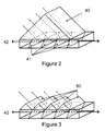
- Figure 2 is a diagrammatic view of a first embodiment of an illumination device produced by the method of the invention.
- Figure 3 is a diagrammatic view of a second embodiment of an illumination device produced by the method of the invention.
- plates 2 (four in this example) of plastics material, preferably made of polymethylmethacrylate (PMMA).
- PMMA polymethylmethacrylate
- the plates 2 are laminated by bonding at their interfaces 4, 6 and 8 and at each interface the surface of a plate 2 is coated with a spectrally selective coating 10 as can be seen in the magnified view of the interface.
- the bonding is achieved by the use of an optical glue forming a layer 12 again as can be seen in the magnified view.
- a first cutting occurs on an oblique plane 20 to give a secondary laminated composite body 22 and a second cutting on an oblique plane 24 yields a final tertiary composite body 26 that is to become the illumination device 30.
- the body 26 is produced with the requisite dimensions for the particular application designated therefor. In this example the length of the device is 30mm with a depth and width each of 5mm.
- the cutting of the plates is effected by water-cooled mechanical cutting or any other appropriate technique that avoids or minimises the risk of cracks propagating due to friction and other thermal reactions which could adversely influence the optical integrity of the device.
- the final preparation of the device per se involves the finishing such as polishing of the external surfaces of the illumination device thus produced.
- the illumination device is now constituted by a laminated composite body encapsulating several coatings on planes defined by the optically reflective coatings at the interfaces of the plates.
- the result of this formation is that the extraction efficiency can approximate to 100% for any polarisation of the incident light travelling through the device, whereas with earlier geometries this efficiency was highly dependent on the polarisation condition. Accordingly the diffraction efficiency of the illumination device of the present invention is largely independent of the polarisation and this beneficial result is realised by the presence of the angular orientation of the reflective surfaces or facets encapsulated in the device.
- the coating is spectrally selective and reflects only a portion of the incoming light (spectral or geometric).
- FIG. 2 of the accompanying drawings there is shown the illumination device of the present invention with a large prism 40 superposed thereon in such manner that it extends across and covers the reflective surfaces or planes 41 within the device. Light enters the device on the path 42.
- the purpose of the prism 40 is to ensure that each emergent spectral component is parallel to each of the other components without deviation by virtue of refraction.
- the prism 40 is bonded by optical glue to the illumination device.
- FIG. 3 there is shown an alternative arrangement for ensuring parallelism of the emergent spectral components.
- a number of smaller prisms 50 is deployed and corresponds to the number of reflective spectral surfaces in the device.
- the deployment of the smaller prisms significantly reduces the overall dimensions of the combination.
- the present invention thus provides a novel and inventive method for producing an illumination device incorporating a laminate structure in which the interfaces of the plates constituting the laminate provide the selective reflective surfaces with appropriate coatings.
- the instant invention provides a compact and robust illumination device suitable for a wide range of applications.
Landscapes
- Physics & Mathematics (AREA)
- General Physics & Mathematics (AREA)
- Optics & Photonics (AREA)
- Non-Portable Lighting Devices Or Systems Thereof (AREA)
Abstract
An illumination device includes a composite body (26) produced from
the lamination of a number of plastic plates (2) bonded together at
interfaces that are provided with light-reflective selective coatings
(10), the laminate being machined across preselected planes (20) to
provide the desired angular orientation, whereby light entering the
illumination device is deflected along parallel emergent paths.
Description
- This invention concerns improvements in or relating to the production of an illumination device.
- In particular the present invention has reference to an illumination device of the kind described in our co-pending European Patent Application No EP 1 055 872 in which there is disclosed an illumination device including a plate for the guidance of an input light beam therethrough, the plate being formed internally thereof with a plurality of micro-prisms for receiving the light beam and for producing an output lightbeam from the input light beam.
- An object of the present invention is to provide an improved method for the production of an illumination device.
- A further object of the present invention is to provide an illumination device having an improved geometry for multiple light splitting.
- According to a first aspect of the present invention a method for the production of an illumination device includes the steps of forming a laminated structure of individual plates of light transmitting material each plate being provided with a selective light-reflective coating, bonding the plates together, and cutting the laminated plates along predetermined angularly orientated planes to produce an illumination device comprising a composite body provided internally thereof with a series of selective light reflective-angularly arrayed coated surfaces.
- The cutting of the laminated plates is effected by employing water-cooled machine cutting or any other appropriate technique that avoids to as great an extent as possible the formation of cracks caused by friction forces or thermal effects between the material and the bonding.
- A further step in the method of production includes finishing such as polishing the faces of the composite body to the desired and required optical quality in terms of flatness and transparency.
- The size of the composite body is chosen for the particular application intended for the illumination device.
- The light transmitting material is conveniently of plastics and may be polymethylmethacrylate (PMMA), a thermoplastic or a thermosetting resin for example polyethylene terephthalate, polybutlyene terephthalate, polycarbonate, polyimide, polyacrylate, polyethersulfone, polyetherimide, or cellulose triacetate resins. As a preference the plastics material to be used is PMMA.
- In the alternative the material from which the plates are made may be glass.
- The plates may be bonded together using an optical glue, which may for example be one available under the trade name 'Norland Optical Adhesive'.
- The reflective coating on each plate may be a spectrally selective coating similar to a holographic filter, reflecting only a portion of the spectral components of the incoming light inside a bandwidth of, for instance, . 2nm to 200nm. The reflective coating on each plate may also be a spectrally insensitive and partially reflective coating.
- According to a second aspect of the present invention there is provided an illumination device produced in accordance with the first aspect and including a composite body having two or more plates provided with a light-reflective selective coating and bonded one to the other along the contacting surfaces thereof, the composite body encapsulating a series of light-reflecting planes internally thereof.
- An illumination device according to the second aspect is further provided with a prism overlying the light transmission paths from the internal light-reflecting planes for the purpose of ensuring that spectral components emerging from the composite body of the device are parallel one to the other in the absence of any deviation that might be occasioned by refraction. The prism is conveniently bonded to the device using an optical glue and may be of the same material from which the device is made.
- In an alternative embodiment an illumination device according to the second aspect is further provided with a number of prisms each overlying a respective light transmission path from an associated internal light-reflecting plane. Similarly, the function of the prisms is to ensure that the spectral components emerging from the device do so in parallel without deviation. It will be appreciated that in deploying a number of prisms each dedicated to a respective light transmission path, the overall physical size of the device is minimised in comparison to the use of a single prism extending across all the light-reflecting planes.
- By way of example only a method for producing an illumination device according to the invention is described below with reference to the accompanying drawings in which:
- Figure 1 is a diagrammatic representation of the method;
- Figure 2 is a diagrammatic view of a first embodiment of an illumination device produced by the method of the invention; and
- Figure 3 is a diagrammatic view of a second embodiment of an illumination device produced by the method of the invention.
- Referring to the drawings there is shown a number of plates 2 (four in this example) of plastics material, preferably made of polymethylmethacrylate (PMMA). The
plates 2 are laminated by bonding at theirinterfaces plate 2 is coated with a spectrallyselective coating 10 as can be seen in the magnified view of the interface. The bonding is achieved by the use of an optical glue forming alayer 12 again as can be seen in the magnified view. - Once the glue has hardened to provide a secure bond between the
plates 2, cutting of the primary laminatedcomposite body 14 can proceed. A first cutting occurs on anoblique plane 20 to give a secondary laminated composite body 22 and a second cutting on anoblique plane 24 yields a finaltertiary composite body 26 that is to become theillumination device 30. Thebody 26 is produced with the requisite dimensions for the particular application designated therefor. In this example the length of the device is 30mm with a depth and width each of 5mm. The cutting of the plates is effected by water-cooled mechanical cutting or any other appropriate technique that avoids or minimises the risk of cracks propagating due to friction and other thermal reactions which could adversely influence the optical integrity of the device. - The final preparation of the device per se involves the finishing such as polishing of the external surfaces of the illumination device thus produced.
- The illumination device is now constituted by a laminated composite body encapsulating several coatings on planes defined by the optically reflective coatings at the interfaces of the plates. The result of this formation is that the extraction efficiency can approximate to 100% for any polarisation of the incident light travelling through the device, whereas with earlier geometries this efficiency was highly dependent on the polarisation condition. Accordingly the diffraction efficiency of the illumination device of the present invention is largely independent of the polarisation and this beneficial result is realised by the presence of the angular orientation of the reflective surfaces or facets encapsulated in the device. The coating is spectrally selective and reflects only a portion of the incoming light (spectral or geometric).
- Referring to Figure 2 of the accompanying drawings there is shown the illumination device of the present invention with a
large prism 40 superposed thereon in such manner that it extends across and covers the reflective surfaces orplanes 41 within the device. Light enters the device on thepath 42. The purpose of theprism 40 is to ensure that each emergent spectral component is parallel to each of the other components without deviation by virtue of refraction. Theprism 40 is bonded by optical glue to the illumination device. - Referring now to Figure 3 there is shown an alternative arrangement for ensuring parallelism of the emergent spectral components. In this embodiment a number of
smaller prisms 50 is deployed and corresponds to the number of reflective spectral surfaces in the device. The deployment of the smaller prisms significantly reduces the overall dimensions of the combination. - The present invention thus provides a novel and inventive method for producing an illumination device incorporating a laminate structure in which the interfaces of the plates constituting the laminate provide the selective reflective surfaces with appropriate coatings.
- The instant invention provides a compact and robust illumination device suitable for a wide range of applications.
Claims (12)
- A method for the production of an illumination device characterised by the steps of forming a laminated structure of individual plates (2) of light transmitting material each plate being provided with a selective light-reflective coating (10), bonding the plates (2) together, and cutting the laminated plates (2) along predetermined angularly orientated planes (20, 24)) to produce an illumination device comprising a composite body (26) provided internally thereof with a series of selective light reflective-angularly arrayed coated surfaces (4, 6, 8).
- A method according to Claim 1 characterised in that the step of cutting the laminated plates (2) is effected in such manner as to minimise frictional or other stresses.
- A method according to Claim 1 or 2 characterised in that the faces of the composite body are subjected to finishing.
- A method according to any one of the preceding claims characterised in that the light transmitting material is a plastics material.
- A method according to any one of the preceding Claims 1 to 3 characterised in that the light transmitting material is glass.
- A method according to any one of the preceding claim characterised in that the plates (2) are bonded together using an optical glue.
- A method according to any one of the preceding claims characterised in that the reflective coating (10) is a spectrally reflective coating.
- A method according to any one of claim 1 to 6 characterised in that the reflective coating (10) is a spectrally insensitive and partially reflective coating.
- An illumination device produced by the method according to any one of the preceding claims characterised in that the device includes a composite body having two or more plates (2) provided with a light-reflective selective coating (10) and bonded one to the other along contacting surfaces thereof, the composite body encapsulating a series of light-reflecting planes internally thereof.
- An illumination device according to Claim 9 characterised in that the device is provided with a prism (40) overlying the light transmission pats from the internal light-reflecting planes.
- An illumination device according to Claim 10 characterised in that the prism is bonded to the device.
- An illumination device according to Claim 9 characterised in that the device is provided with a number of prisms (50) each overlying a respective light transmission path from an associated internal light-reflecting plane.
Priority Applications (1)
| Application Number | Priority Date | Filing Date | Title |
|---|---|---|---|
| EP03076129A EP1469324A1 (en) | 2003-04-16 | 2003-04-16 | An illumination device formed by cutting and laminating coated plates |
Applications Claiming Priority (1)
| Application Number | Priority Date | Filing Date | Title |
|---|---|---|---|
| EP03076129A EP1469324A1 (en) | 2003-04-16 | 2003-04-16 | An illumination device formed by cutting and laminating coated plates |
Publications (1)
| Publication Number | Publication Date |
|---|---|
| EP1469324A1 true EP1469324A1 (en) | 2004-10-20 |
Family
ID=32892933
Family Applications (1)
| Application Number | Title | Priority Date | Filing Date |
|---|---|---|---|
| EP03076129A Withdrawn EP1469324A1 (en) | 2003-04-16 | 2003-04-16 | An illumination device formed by cutting and laminating coated plates |
Country Status (1)
| Country | Link |
|---|---|
| EP (1) | EP1469324A1 (en) |
Cited By (1)
| Publication number | Priority date | Publication date | Assignee | Title |
|---|---|---|---|---|
| CN100449335C (en) * | 2005-06-01 | 2009-01-07 | 富士能佐野株式会社 | Method for manufacture prism |
Citations (5)
| Publication number | Priority date | Publication date | Assignee | Title |
|---|---|---|---|---|
| US5221982A (en) * | 1991-07-05 | 1993-06-22 | Faris Sadeg M | Polarizing wavelength separator |
| JPH0980211A (en) * | 1995-09-12 | 1997-03-28 | Matsushita Electric Ind Co Ltd | Integrated optical element and manufacturing method thereof |
| JP2001343508A (en) * | 2000-06-01 | 2001-12-14 | Toyo Commun Equip Co Ltd | Optical device and method of manufacturing the same |
| JP2002040246A (en) * | 2000-07-21 | 2002-02-06 | Hoya Optics Kk | Polarization converting element, method for manufacturing the same and liquid crystal projector |
| EP1256822A2 (en) * | 1996-03-12 | 2002-11-13 | Seiko Epson Corporation | Polarized light separator, method of manufacturing the same, and projection display |
-
2003
- 2003-04-16 EP EP03076129A patent/EP1469324A1/en not_active Withdrawn
Patent Citations (5)
| Publication number | Priority date | Publication date | Assignee | Title |
|---|---|---|---|---|
| US5221982A (en) * | 1991-07-05 | 1993-06-22 | Faris Sadeg M | Polarizing wavelength separator |
| JPH0980211A (en) * | 1995-09-12 | 1997-03-28 | Matsushita Electric Ind Co Ltd | Integrated optical element and manufacturing method thereof |
| EP1256822A2 (en) * | 1996-03-12 | 2002-11-13 | Seiko Epson Corporation | Polarized light separator, method of manufacturing the same, and projection display |
| JP2001343508A (en) * | 2000-06-01 | 2001-12-14 | Toyo Commun Equip Co Ltd | Optical device and method of manufacturing the same |
| JP2002040246A (en) * | 2000-07-21 | 2002-02-06 | Hoya Optics Kk | Polarization converting element, method for manufacturing the same and liquid crystal projector |
Non-Patent Citations (3)
| Title |
|---|
| PATENT ABSTRACTS OF JAPAN vol. 1997, no. 07 31 July 1997 (1997-07-31) * |
| PATENT ABSTRACTS OF JAPAN vol. 2002, no. 04 4 August 2002 (2002-08-04) * |
| PATENT ABSTRACTS OF JAPAN vol. 2002, no. 06 4 June 2002 (2002-06-04) * |
Cited By (1)
| Publication number | Priority date | Publication date | Assignee | Title |
|---|---|---|---|---|
| CN100449335C (en) * | 2005-06-01 | 2009-01-07 | 富士能佐野株式会社 | Method for manufacture prism |
Similar Documents
| Publication | Publication Date | Title |
|---|---|---|
| JP6876656B2 (en) | Optical component array | |
| KR102623956B1 (en) | Method for manufacturing composite light guiding optical elements | |
| WO2004040344B1 (en) | Optical multiplexer/demultiplexer and production method for optical multiplexer/demultiplexer | |
| JP2015522852A5 (en) | ||
| JP2002520669A (en) | Optical panel with small entrance and method of manufacturing optical panel with small entrance | |
| CN102089689A (en) | Optical splitter device | |
| JP2017138356A (en) | Optical waveguide sheet, optical transmission module, and optical waveguide sheet manufacturing method | |
| US7943895B2 (en) | Wavelength splitting element, method for manufacturing the same and optical module | |
| JP2003004992A (en) | Optical transmitting / receiving module and manufacturing method thereof | |
| WO2013176673A1 (en) | Fiber connector assembly | |
| CN100422777C (en) | Optical combiner and demultiplexer and method for manufacturing optical combiner and demultiplexer | |
| JP2000292631A (en) | Optical waveguide component and optical multiplexing / demultiplexing device | |
| KR101466385B1 (en) | spectral module and method of manufacturing the same | |
| CN110895362B (en) | Optical fiber module | |
| JP2000199810A (en) | Method for manufacturing optical device | |
| TWI283761B (en) | Composite-type optical device | |
| CA2665111A1 (en) | Hybrid planar lightwave circuit with reflective gratings | |
| JP2005241998A (en) | Optical filter unit and optical filter module | |
| JP2001343508A (en) | Optical device and method of manufacturing the same | |
| JP2008139731A (en) | Manufacturing method of right triangle prism | |
| JPH09258044A (en) | Waveguide type optical device with optical filter | |
| JPH04361208A (en) | Optical multiplexer/demultiplexer and manufacture of the same | |
| JP2007249090A (en) | Polarization conversion element and its manufacturing method | |
| JP2006505817A (en) | Support element for mounting optical element and manufacturing method thereof | |
| JP2007219201A (en) | Optical element and manufacturing method thereof |
Legal Events
| Date | Code | Title | Description |
|---|---|---|---|
| PUAI | Public reference made under article 153(3) epc to a published international application that has entered the european phase |
Free format text: ORIGINAL CODE: 0009012 |
|
| AK | Designated contracting states |
Kind code of ref document: A1 Designated state(s): AT BE BG CH CY CZ DE DK EE ES FI FR GB GR HU IE IT LI LU MC NL PT RO SE SI SK TR |
|
| AX | Request for extension of the european patent |
Extension state: AL LT LV MK |
|
| AKX | Designation fees paid | ||
| REG | Reference to a national code |
Ref country code: DE Ref legal event code: 8566 |
|
| STAA | Information on the status of an ep patent application or granted ep patent |
Free format text: STATUS: THE APPLICATION IS DEEMED TO BE WITHDRAWN |
|
| 18D | Application deemed to be withdrawn |
Effective date: 20050420 |