EP1469204A1 - Impeller - Google Patents
Impeller Download PDFInfo
- Publication number
- EP1469204A1 EP1469204A1 EP03701819A EP03701819A EP1469204A1 EP 1469204 A1 EP1469204 A1 EP 1469204A1 EP 03701819 A EP03701819 A EP 03701819A EP 03701819 A EP03701819 A EP 03701819A EP 1469204 A1 EP1469204 A1 EP 1469204A1
- Authority
- EP
- European Patent Office
- Prior art keywords
- main
- main plate
- impeller
- plate
- impellers
- Prior art date
- Legal status (The legal status is an assumption and is not a legal conclusion. Google has not performed a legal analysis and makes no representation as to the accuracy of the status listed.)
- Granted
Links
Images


Classifications
-
- F—MECHANICAL ENGINEERING; LIGHTING; HEATING; WEAPONS; BLASTING
- F04—POSITIVE - DISPLACEMENT MACHINES FOR LIQUIDS; PUMPS FOR LIQUIDS OR ELASTIC FLUIDS
- F04D—NON-POSITIVE-DISPLACEMENT PUMPS
- F04D29/00—Details, component parts, or accessories
- F04D29/18—Rotors
- F04D29/20—Mounting rotors on shafts
-
- F—MECHANICAL ENGINEERING; LIGHTING; HEATING; WEAPONS; BLASTING
- F04—POSITIVE - DISPLACEMENT MACHINES FOR LIQUIDS; PUMPS FOR LIQUIDS OR ELASTIC FLUIDS
- F04D—NON-POSITIVE-DISPLACEMENT PUMPS
- F04D1/00—Radial-flow pumps, e.g. centrifugal pumps; Helico-centrifugal pumps
- F04D1/06—Multi-stage pumps
-
- F—MECHANICAL ENGINEERING; LIGHTING; HEATING; WEAPONS; BLASTING
- F04—POSITIVE - DISPLACEMENT MACHINES FOR LIQUIDS; PUMPS FOR LIQUIDS OR ELASTIC FLUIDS
- F04D—NON-POSITIVE-DISPLACEMENT PUMPS
- F04D29/00—Details, component parts, or accessories
- F04D29/02—Selection of particular materials
- F04D29/026—Selection of particular materials especially adapted for liquid pumps
-
- F—MECHANICAL ENGINEERING; LIGHTING; HEATING; WEAPONS; BLASTING
- F04—POSITIVE - DISPLACEMENT MACHINES FOR LIQUIDS; PUMPS FOR LIQUIDS OR ELASTIC FLUIDS
- F04D—NON-POSITIVE-DISPLACEMENT PUMPS
- F04D29/00—Details, component parts, or accessories
- F04D29/18—Rotors
- F04D29/22—Rotors specially for centrifugal pumps
- F04D29/2205—Conventional flow pattern
- F04D29/2222—Construction and assembly
- F04D29/2227—Construction and assembly for special materials
-
- F—MECHANICAL ENGINEERING; LIGHTING; HEATING; WEAPONS; BLASTING
- F05—INDEXING SCHEMES RELATING TO ENGINES OR PUMPS IN VARIOUS SUBCLASSES OF CLASSES F01-F04
- F05D—INDEXING SCHEME FOR ASPECTS RELATING TO NON-POSITIVE-DISPLACEMENT MACHINES OR ENGINES, GAS-TURBINES OR JET-PROPULSION PLANTS
- F05D2230/00—Manufacture
- F05D2230/50—Building or constructing in particular ways
- F05D2230/54—Building or constructing in particular ways by sheet metal manufacturing
-
- F—MECHANICAL ENGINEERING; LIGHTING; HEATING; WEAPONS; BLASTING
- F05—INDEXING SCHEMES RELATING TO ENGINES OR PUMPS IN VARIOUS SUBCLASSES OF CLASSES F01-F04
- F05D—INDEXING SCHEME FOR ASPECTS RELATING TO NON-POSITIVE-DISPLACEMENT MACHINES OR ENGINES, GAS-TURBINES OR JET-PROPULSION PLANTS
- F05D2300/00—Materials; Properties thereof
- F05D2300/10—Metals, alloys or intermetallic compounds
- F05D2300/17—Alloys
- F05D2300/171—Steel alloys
Definitions
- the present invention relates to an impeller used for a pump or the like, and more particularly to an impeller manufactured by press-forming a sheet metal material.
- Impellers used for a pump or the like are mostly manufactured by welding parts, into which a sheet metal material is press-formed, with an automatic welding machine.
- FIG. 5 is a schematic cross-sectional view of a conventional impeller. As shown in FIG. 5, the impeller 100 is composed of a disk-like main plate 110, blades 120 joined to the main plate 110, and a side plate 130 having a suction port.
- a sheet metal material is die-cut and press-formed to produce the blades 120 of the impeller 100, and then the blades 120 of the impeller 100 are joined to the main plate 110 by welding.
- radially inner end portions 122 of the blades 120 which are joined to the main plate 110 are so sharp that a large load is applied to a die portion to die-cut the radially inner end portions 122, and that the die portion is worn away in a short term.
- main plates 110 are piled on one another before blades 120 are joined to the main plates 110.
- Each one of piled main plates 110 is raised, transferred, and welded by the automatic welding machine.
- the main plate 110 is of a flat disk, adjacent main plates are adhered and attracted to each other in the case where the main plates are piled on one another as described above. Accordingly, when each one of the main plates 110 is to be raised, an adjacent main plate is also raised and transferred together to cause problems such as error interruption of the welding machine.
- the present invention has been made in view of the above drawbacks of the prior art. It is, therefore, an object of the present invention to provide an impeller which can prolong a lifetime of a die for forming a blade and prevent error interruption of a welding machine to enhance productivity.
- an impeller having a disk-like main plate, a blade joined to the main plate, and a side plate having a suction port, characterized in that a boss hole is formed in a central portion of the main plate for attaching a boss which engages with a pump shaft to the boss hole, wherein a step portion is formed around the boss hole, which is formed in the main plate, by drawing.
- a step portion is formed around a boss hole, a gap is formed between adjacent main plates when the main plates are piled on one another. Therefore, even when the main plates are piled on one another before the blade is joined to the main plates, a gap is formed between adjacent main plates to thereby prevent these main plates from being adhered or attracted to each other. Thus, adjacent main plates are prevented from being raised together, and error interruption of a welding machine is prevented to enhance productivity of impellers.
- a gap formed by the step portions of adjacent main plates be set to be in a rage of 0.3 mm to 0.4 mm.
- an impeller having a disk-like main plate, a blade joined to the main plate, and a side plate having a suction port, characterized in that a radially inner end portion of the blade which is joined to the main plate is rounded.
- a radially inner end portion of the blade which is joined to the main plate is rounded. Accordingly, when the blade is formed by die-cutting a sheet metal material, no large loads are applied to a die portion to die-cut the radially inner end portion. Thus, it is possible to reduce abrasion of the die portion. Therefore, it is possible to prolong a lifetime of the die portion and enhance productivity of impellers.
- a multistage pump characterized by comprising a plurality of intermediate casings, the aforementioned impellers housed in respective intermediate casings, and a main shaft for supporting the impellers.
- FIG. 1 is a vertical cross-sectional view showing an impeller according to an embodiment of the present invention
- FIG. 2 is a schematic view showing a state in which main plates of impellers according to an embodiment of the present invention are piled on one another
- FIG. 3 is a partial enlarged view of FIG. 2.
- an impeller 1 has a main plate 10, blades 20 joined to the main plate 10, and a side plate 30 having a suction port.
- a sheet metal material such as stainless steel is die-cut into a disk-like shape to form the main plate 10.
- a boss hole 12 is formed in a central portion of the main plate 10 for attaching a boss which engages with a pump shaft to the boss hole. Drawing is carried out by a press to form a step portion 14, which is raised upward, around the boss hole 12.
- step portion 14 is thus formed around the boss hole 12, as shown in FIGS. 2 and 3, when the main plates 10 are piled on one another, a gap d is formed between adjacent main plates 10. Therefore, even when the main plates 10 are piled on one another before the blades 20 are joined to the main plates 10, a gap d is formed between adjacent main plates 10 to thereby prevent these main plates 10 from being adhered or attracted to each other. Thus, adjacent main plates 10 are prevented from being raised together, and error interruption of a welding machine is prevented to enhance productivity of impellers.
- the gap d be set to be in a range of 0.3 mm to 0.4 mm.
- radially inner end portions 22 of the blades 20 which are joined to the main plate 10 are rounded. Accordingly, when the blades 20 are formed by die-cutting a sheet metal material, no large loads are applied to a die portion to die-cut the radially inner end portions 22. Thus, it is possible to reduce abrasion of the die portion. Therefore, it is possible to prolong a lifetime of the die portion and enhance productivity of impellers. Although there has been described in the present embodiment an example in which the radially inner end portions 22 are rounded, the radially inner end portions 22 may be formed so as to have an obtuse angle.
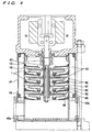
- FIG. 4 is a vertical cross-sectional view showing a multistage pump using impellers according to the present invention.
- a plurality of intermediate casings 42 connected to each other is housed in an outer casing 41, and impellers 1 attached to a main shaft 43 are housed in respective intermediate casings 42.
- a lower casing 45 is connected to a lower end portion of the outer casing 41.
- the lower casing 45 has a suction port 45a and a discharge port 45b.
- An impeller attachment portion of the main shaft 43 comprises a spline shaft portion and has a plurality of keyways formed in parallel to an axial portion.
- the impellers 1 are attached to the main shaft 43 by spline fitting.
- Distance pieces 46 are disposed between preceding and subsequent stages of the impellers 1 so as to be fitted into the spline shaft portion of the main shaft 43.
- the intermediate casing 42 is formed substantially into a cylindrical receptacle.
- the intermediate casing 42 is produced by press-forming a steel plate.
- a relief plate 47 is attached to a bottom portion 44 of each of the intermediate casings 42 by welding.
- Return vanes 49 are interposed between the relief plate 47 and a side plate 48 and attached to the relief plate 47 and the side plate 48 by welding.
- the relief plate 47 and the adjacent intermediate casing 42 form a space in which an O-ring 50 is fitted.
- a pumping liquid drawn from the suction port 45a of the lower casing 45 is pressurized by the impellers 1 rotated by the main shaft 43.
- the pressurized pumping liquid is introduced into a suction portion of a subsequent impeller 1 through a passage formed by the return vanes 49 interposed between the relief plate 47 and the side plate 48.
- the pumping liquid is pressurized by each stage of the impellers 1, recovered in pressure while flowing through a passage formed by each stage of the return vanes 49, and finally discharged from the discharge port 45b of the lower casing 45 to the exterior of the pump.
- a gap is formed between adjacent main plates when the main plates are piled on one another. Therefore, even when the main plates are piled on one another before the blade is joined to the main plates, a gap is formed between adjacent main plates to thereby prevent these main plates from being adhered or attracted to each other. Thus, adjacent main plates are prevented from being raised together, and error interruption of a welding machine is prevented to enhance productivity of impellers.
- a radially inner end portion of the blade which is joined to the main plate is rounded. Accordingly, when the blade is formed by die-cutting a sheet metal material, no large loads are applied to a die portion to die-cut the radially inner end portion. Thus, it is possible to reduce abrasion of the die portion. Therefore, it is possible to prolong a lifetime of the die portion and enhance productivity of impellers.
- the present invention can suitably be used for an impeller manufactured by press-forming a sheet metal material.
Landscapes
- Engineering & Computer Science (AREA)
- Mechanical Engineering (AREA)
- General Engineering & Computer Science (AREA)
- Structures Of Non-Positive Displacement Pumps (AREA)
Abstract
Description
Claims (4)
- An impeller having a disk-like main plate, a blade joined to said main plate, and a side plate having a suction port, characterized in that:wherein a step portion is formed around the boss hole, which is formed in said main plate, by drawing.a boss hole is formed in a central portion of said main plate for attaching a boss which engages with a pump shaft to said boss hole,
- The impeller as recited in claim 1, characterized in that when a plurality of main plates are piled on one another, a gap formed by said step portions of adjacent main plates is set to be in a rage of 0.3 mm to 0.4 mm.
- An impeller having a disk-like main plate, a blade joined to said main plate, and a side plate having a suction port, characterized in that:a radially inner end portion of said blade which is joined to said main plate is rounded.
- A multistage pump characterized by comprising a plurality of intermediate casings, impellers, as recited in any one of claims 1 thorough 3, housed in respective intermediate casings, and a main shaft for supporting said impellers.
Applications Claiming Priority (3)
| Application Number | Priority Date | Filing Date | Title |
|---|---|---|---|
| JP2002012186 | 2002-01-21 | ||
| JP2002012186A JP3953328B2 (en) | 2002-01-21 | 2002-01-21 | Impeller |
| PCT/JP2003/000463 WO2003062646A1 (en) | 2002-01-21 | 2003-01-21 | Impeller |
Publications (3)
| Publication Number | Publication Date |
|---|---|
| EP1469204A1 true EP1469204A1 (en) | 2004-10-20 |
| EP1469204A4 EP1469204A4 (en) | 2010-04-14 |
| EP1469204B1 EP1469204B1 (en) | 2015-10-14 |
Family
ID=27606037
Family Applications (1)
| Application Number | Title | Priority Date | Filing Date |
|---|---|---|---|
| EP03701819.9A Expired - Lifetime EP1469204B1 (en) | 2002-01-21 | 2003-01-21 | Impeller |
Country Status (6)
| Country | Link |
|---|---|
| US (1) | US7247001B2 (en) |
| EP (1) | EP1469204B1 (en) |
| JP (1) | JP3953328B2 (en) |
| CN (1) | CN100395455C (en) |
| DK (1) | DK1469204T3 (en) |
| WO (1) | WO2003062646A1 (en) |
Cited By (2)
| Publication number | Priority date | Publication date | Assignee | Title |
|---|---|---|---|---|
| CN102011749A (en) * | 2010-12-23 | 2011-04-13 | 江苏国泉泵业制造有限公司 | Round head punched blade non-clogging impeller |
| CN111706553A (en) * | 2020-06-23 | 2020-09-25 | 西安航空学院 | Tightening nut to prevent low-pressure inlet cavitation |
Families Citing this family (7)
| Publication number | Priority date | Publication date | Assignee | Title |
|---|---|---|---|---|
| JP4593962B2 (en) * | 2004-04-26 | 2010-12-08 | 株式会社荏原製作所 | Centrifugal pump and method of manufacturing centrifugal pump |
| JP4633396B2 (en) * | 2004-07-16 | 2011-02-16 | 株式会社荏原製作所 | Centrifugal pump |
| WO2011106780A1 (en) | 2010-02-26 | 2011-09-01 | Ventions, Llc | Small scale high speed turbomachinery |
| CN103032374B (en) * | 2013-01-17 | 2015-06-24 | 福州福发发电设备有限公司 | Intermediate-frequency power generator fan and production process thereof |
| CN104279188B (en) * | 2014-10-29 | 2017-08-01 | 珠海格力电器股份有限公司 | Centrifugal fan and air conditioner with same |
| EP3181908B1 (en) * | 2015-12-17 | 2020-05-13 | Grundfos Holding A/S | Multi-stage centrifugal pump having tension anchors made of sheet metal |
| WO2020118461A1 (en) * | 2018-12-14 | 2020-06-18 | Universidad Técnica Federico Santa María | Lifting platform for loading and unloading gas cylinders |
Family Cites Families (25)
| Publication number | Priority date | Publication date | Assignee | Title |
|---|---|---|---|---|
| US2228750A (en) * | 1939-09-07 | 1941-01-14 | Rexair Inc | Vacuum cleaner construction |
| FR1300199A (en) * | 1961-06-17 | 1962-08-03 | Centrifugal pump impeller, especially for small pumps | |
| US3265001A (en) * | 1964-04-24 | 1966-08-09 | Red Jacket Mfg Company | Centrifugal pump |
| US3340813A (en) * | 1965-06-11 | 1967-09-12 | Itt | Centrifugal pumps |
| DK115677B (en) * | 1966-08-09 | 1969-10-27 | Grundfos As | Centrifugal pump. |
| US3884595A (en) * | 1974-05-15 | 1975-05-20 | Dresser Ind | Impeller and shaft assembly |
| FI61235C (en) | 1979-01-29 | 1982-06-10 | Nokia Oy Ab | VINGHJUL HOS EN CENTRIFUGALFLAEKT |
| US4278399A (en) * | 1979-06-21 | 1981-07-14 | Kobe, Inc. | Pumping stage for multi-stage centrifugal pump |
| CA1155712A (en) * | 1979-10-29 | 1983-10-25 | Rockwell International Corporation | Composite centrifugal impeller for slurry pumps |
| IT8030902U1 (en) * | 1980-12-29 | 1982-06-29 | Lowara Spa | MULTISTAGE PUMP STAGE CONTAINER |
| DE3520218A1 (en) * | 1984-06-08 | 1985-12-12 | Hitachi, Ltd., Tokio/Tokyo | IMPELLER FOR A RADIAL BLOWER |
| GB2251035A (en) * | 1990-12-20 | 1992-06-24 | Dunphy Oil And Gas Burners Lim | Centrifugal fan |
| US5234317A (en) * | 1990-12-25 | 1993-08-10 | Ebara Corporation | Sheet metal interstage casing for a pump |
| GB2260788A (en) * | 1991-10-05 | 1993-04-28 | Jaguar Cars | Pump impeller |
| JP3281432B2 (en) * | 1993-01-29 | 2002-05-13 | 東芝キヤリア株式会社 | Multi-blade fan and method of manufacturing the same |
| US5336050A (en) * | 1993-05-06 | 1994-08-09 | Penn Ventilator Co. Inc. | Ventilator fan device |
| US5328332A (en) * | 1993-05-25 | 1994-07-12 | Chiang Swea T | Wheel fan of range hood |
| JPH0719195A (en) * | 1993-06-29 | 1995-01-20 | Atago Seisakusho:Kk | Multiblade fan |
| JP3020189B2 (en) | 1993-07-05 | 2000-03-15 | アネルバ株式会社 | Thin film formation method by bias sputtering |
| JPH0738694A (en) | 1993-07-23 | 1995-02-07 | Sharp Corp | Fax machine |
| CA2131243A1 (en) | 1993-09-27 | 1995-03-28 | Kenneth R. Paulson | Process for forming a phosphor |
| JPH0738694U (en) * | 1993-12-20 | 1995-07-14 | 株式会社川本製作所 | Centrifugal pump steel impeller |
| US6220819B1 (en) * | 2000-01-12 | 2001-04-24 | Industrial Technology Research Institute | Centrifugal pump impeller |
| US6267555B1 (en) * | 2000-01-12 | 2001-07-31 | Industrial Technology Research Institute | Sheet metal casing for multistage pump and method for manufacturing the same |
| TW415545U (en) * | 2000-02-02 | 2000-12-11 | Ind Tech Res Inst | Pump housing structure improvement of multi-step type pump |
-
2002
- 2002-01-21 JP JP2002012186A patent/JP3953328B2/en not_active Expired - Lifetime
-
2003
- 2003-01-21 DK DK03701819.9T patent/DK1469204T3/en active
- 2003-01-21 WO PCT/JP2003/000463 patent/WO2003062646A1/en not_active Ceased
- 2003-01-21 CN CNB038025434A patent/CN100395455C/en not_active Expired - Lifetime
- 2003-01-21 EP EP03701819.9A patent/EP1469204B1/en not_active Expired - Lifetime
- 2003-01-21 US US10/501,886 patent/US7247001B2/en not_active Expired - Lifetime
Cited By (2)
| Publication number | Priority date | Publication date | Assignee | Title |
|---|---|---|---|---|
| CN102011749A (en) * | 2010-12-23 | 2011-04-13 | 江苏国泉泵业制造有限公司 | Round head punched blade non-clogging impeller |
| CN111706553A (en) * | 2020-06-23 | 2020-09-25 | 西安航空学院 | Tightening nut to prevent low-pressure inlet cavitation |
Also Published As
| Publication number | Publication date |
|---|---|
| DK1469204T3 (en) | 2015-12-21 |
| JP3953328B2 (en) | 2007-08-08 |
| US7247001B2 (en) | 2007-07-24 |
| CN100395455C (en) | 2008-06-18 |
| JP2003214385A (en) | 2003-07-30 |
| EP1469204A4 (en) | 2010-04-14 |
| WO2003062646A1 (en) | 2003-07-31 |
| EP1469204B1 (en) | 2015-10-14 |
| US20050002789A1 (en) | 2005-01-06 |
| CN1692230A (en) | 2005-11-02 |
Similar Documents
| Publication | Publication Date | Title |
|---|---|---|
| EP0492604B1 (en) | Interstage casing for a pump made of sheet metal | |
| US7247001B2 (en) | Impeller | |
| US5310310A (en) | Pump casing made of sheet metal | |
| US7648337B2 (en) | Multistage pump | |
| JPH06280794A (en) | Intermediate casing made of steel plate for pump and manufacture thereof | |
| US11236750B2 (en) | Pump with a wear ring | |
| EP1711687A1 (en) | Casing for a centrifugal pump | |
| JPH06280795A (en) | Intermediate casing made of steel plate and multistage pump using the intermediate casing | |
| JP2002031073A (en) | Multi-stage pump | |
| ZA200507202B (en) | Liquid ring pump | |
| US6641369B2 (en) | Liquid ring compressor with thin distribution plate | |
| WO1999017022A1 (en) | A fluid machinery, a flange for fluid machinery, and a method for manufacturing them | |
| CN218093459U (en) | Pressure reduction type balance mechanism of multistage centrifugal pump | |
| JPH07224782A (en) | Multistage centrifugal pump | |
| JP2581188Y2 (en) | Pump impeller | |
| JP4090675B2 (en) | Multistage pump | |
| JP2024003479A (en) | Press impeller and pump device | |
| CN201246346Y (en) | Pump inlet structure of vertical low flash cold circulation axial-flow pump | |
| WO2020204712A1 (en) | Pump | |
| JPS647238B2 (en) | ||
| HK1077612A (en) | Multistage pump | |
| JP2018025131A (en) | Casing liner for sewage pump, sewage pump, and method for manufacturing casing liner for sewage pump | |
| JPS5836198B2 (en) | Vortex pump impeller |
Legal Events
| Date | Code | Title | Description |
|---|---|---|---|
| PUAI | Public reference made under article 153(3) epc to a published international application that has entered the european phase |
Free format text: ORIGINAL CODE: 0009012 |
|
| 17P | Request for examination filed |
Effective date: 20040726 |
|
| AK | Designated contracting states |
Kind code of ref document: A1 Designated state(s): AT BE BG CH CY CZ DE DK EE ES FI FR GB GR HU IE IT LI LU MC NL PT SE SI SK TR |
|
| A4 | Supplementary search report drawn up and despatched |
Effective date: 20100312 |
|
| RIC1 | Information provided on ipc code assigned before grant |
Ipc: F04D 29/22 20060101ALI20100308BHEP Ipc: F04D 29/24 20060101ALI20100308BHEP Ipc: F04D 29/62 20060101AFI20030805BHEP Ipc: F04D 29/02 20060101ALI20100308BHEP |
|
| 17Q | First examination report despatched |
Effective date: 20100806 |
|
| GRAP | Despatch of communication of intention to grant a patent |
Free format text: ORIGINAL CODE: EPIDOSNIGR1 |
|
| RIC1 | Information provided on ipc code assigned before grant |
Ipc: F04D 29/24 20060101ALI20150304BHEP Ipc: F04D 29/02 20060101ALI20150304BHEP Ipc: F04D 29/62 20060101AFI20150304BHEP Ipc: F04D 29/22 20060101ALI20150304BHEP |
|
| INTG | Intention to grant announced |
Effective date: 20150323 |
|
| GRAS | Grant fee paid |
Free format text: ORIGINAL CODE: EPIDOSNIGR3 |
|
| GRAA | (expected) grant |
Free format text: ORIGINAL CODE: 0009210 |
|
| AK | Designated contracting states |
Kind code of ref document: B1 Designated state(s): DE DK IT |
|
| REG | Reference to a national code |
Ref country code: DE Ref legal event code: R096 Ref document number: 60348136 Country of ref document: DE |
|
| REG | Reference to a national code |
Ref country code: DK Ref legal event code: T3 Effective date: 20151217 |
|
| REG | Reference to a national code |
Ref country code: DE Ref legal event code: R097 Ref document number: 60348136 Country of ref document: DE |
|
| PLBE | No opposition filed within time limit |
Free format text: ORIGINAL CODE: 0009261 |
|
| STAA | Information on the status of an ep patent application or granted ep patent |
Free format text: STATUS: NO OPPOSITION FILED WITHIN TIME LIMIT |
|
| 26N | No opposition filed |
Effective date: 20160715 |
|
| PGFP | Annual fee paid to national office [announced via postgrant information from national office to epo] |
Ref country code: DK Payment date: 20220110 Year of fee payment: 20 Ref country code: DE Payment date: 20211130 Year of fee payment: 20 |
|
| PGFP | Annual fee paid to national office [announced via postgrant information from national office to epo] |
Ref country code: IT Payment date: 20211213 Year of fee payment: 20 |
|
| REG | Reference to a national code |
Ref country code: DE Ref legal event code: R071 Ref document number: 60348136 Country of ref document: DE |
|
| REG | Reference to a national code |
Ref country code: DK Ref legal event code: EUP Expiry date: 20230121 |