EP1469166B1 - Antriebsvorrichtung für verstellbare Leitschaufeln einer Turbomaschine - Google Patents
Antriebsvorrichtung für verstellbare Leitschaufeln einer Turbomaschine Download PDFInfo
- Publication number
- EP1469166B1 EP1469166B1 EP04291011A EP04291011A EP1469166B1 EP 1469166 B1 EP1469166 B1 EP 1469166B1 EP 04291011 A EP04291011 A EP 04291011A EP 04291011 A EP04291011 A EP 04291011A EP 1469166 B1 EP1469166 B1 EP 1469166B1
- Authority
- EP
- European Patent Office
- Prior art keywords
- fingers
- radial
- links
- bridges
- control ring
- Prior art date
- Legal status (The legal status is an assumption and is not a legal conclusion. Google has not performed a legal analysis and makes no representation as to the accuracy of the status listed.)
- Expired - Lifetime
Links
Images

Classifications
-
- F—MECHANICAL ENGINEERING; LIGHTING; HEATING; WEAPONS; BLASTING
- F01—MACHINES OR ENGINES IN GENERAL; ENGINE PLANTS IN GENERAL; STEAM ENGINES
- F01D—NON-POSITIVE DISPLACEMENT MACHINES OR ENGINES, e.g. STEAM TURBINES
- F01D17/00—Regulating or controlling by varying flow
- F01D17/10—Final actuators
- F01D17/12—Final actuators arranged in stator parts
- F01D17/14—Final actuators arranged in stator parts varying effective cross-sectional area of nozzles or guide conduits
- F01D17/16—Final actuators arranged in stator parts varying effective cross-sectional area of nozzles or guide conduits by means of nozzle vanes
- F01D17/162—Final actuators arranged in stator parts varying effective cross-sectional area of nozzles or guide conduits by means of nozzle vanes for axial flow, i.e. the vanes turning around axes which are essentially perpendicular to the rotor centre line
-
- Y—GENERAL TAGGING OF NEW TECHNOLOGICAL DEVELOPMENTS; GENERAL TAGGING OF CROSS-SECTIONAL TECHNOLOGIES SPANNING OVER SEVERAL SECTIONS OF THE IPC; TECHNICAL SUBJECTS COVERED BY FORMER USPC CROSS-REFERENCE ART COLLECTIONS [XRACs] AND DIGESTS
- Y02—TECHNOLOGIES OR APPLICATIONS FOR MITIGATION OR ADAPTATION AGAINST CLIMATE CHANGE
- Y02T—CLIMATE CHANGE MITIGATION TECHNOLOGIES RELATED TO TRANSPORTATION
- Y02T50/00—Aeronautics or air transport
- Y02T50/60—Efficient propulsion technologies, e.g. for aircraft
Definitions
- the invention relates to a variable-pitch blade control device in a turbomachine such as a turboprop or an airplane turbojet engine.
- the adjustment of the angular setting of certain stator vanes in such a turbomachine is intended to optimize the efficiency of this turbomachine and to reduce its fuel consumption in the various flight configurations.
- This adjustment is generally carried out, for one or more rows of blades, by means of a control ring which externally surrounds the stator of the turbomachine and which is displaceable in rotation about the longitudinal axis of the stator by a motor means. such as a cylinder or an electric motor.
- the rotation of the ring is transmitted by rods to the blades of the row, each rod being secured to a blade at one of its ends and carrying at its other end a radial finger which is engaged in a cylindrical housing of the control ring.
- the stator casing is formed of two semi-cylindrical shells having longitudinal junction flanges, which protrude outside the casing. Due to the presence of these longitudinal flanges, each control ring is formed of two approximately semi-circular elements rigidly connected to each other at their ends by two bridges which are arranged astride the flanges of the housing and allow an angular displacement of the ring around the longitudinal axis of the housing.
- Such a housing is disclosed in GB-A-1 216 920.
- the radial fingers of the links extend inwardly when they are intended to be received in housings of substantially semicircular elements of the ring, and extend radially outwardly when they are intended to be received in cylindrical housings of the bridges, the latter being further apart from the longitudinal axis of the casing than the semicircular elements of the ring.
- the present invention is intended in particular to provide a simple, effective and inexpensive solution to this problem.
- variable-pitch blade control device in a turbomachine, these blades comprising radial pivots mounted in bearings of a housing and connected by links to a control ring surrounding the housing externally, this ring comprising two substantially semicircular elements rigidly connected to each other at their ends by bridges arranged astride longitudinal flanges of the casing, characterized in that the links are rotatably mounted on radial finger ends borne by the semicircular elements and by the jumpers of the control ring and in that the fingers carried by the semicircular elements extend radially outside these elements, and the fingers carried by the bridges extend radially inside these bridges so that the points of rotation of the rods on these fingers are at the same distance from the longitudinal axis d e the ring, for the radial fingers carried by the semicircular elements and for those carried by the bridge of the control ring.
- the points of rotation of the rods are located in the contact zones between the rods and the radial fingers, and no longer between the radial fingers and their cylindrical housings, and it is guaranteed that that an angular displacement of the ring results in the same rotation of all the blades of the row.
- the rods are rotatably mounted on the radial fingers.
- the aforesaid radial fingers are mounted in radial cylindrical housings of the semicircular elements and the jumpers of the control ring and are held there by bent lugs fixed by screws on these elements and bridges, and cooperating with the ends of the fingers on which the links are mounted.
- the aforesaid radial fingers are crimped at their opposite ends to the links in cylindrical housings of the semicircular elements and the bridge of the control ring.
- This assembly results in a gain in weight since it allows the removal of the aforementioned bent legs and their fixing screws on the semicircular elements and the jumpers of the control ring.
- retaining means of the rods are mounted on the radial fingers and comprise U-shaped parts whose wings have openings for passage of the radial fingers and are on either side of a flange of the radial fingers.
- These retaining means may be light plates that do not increase the total weight penalizing way.
- FIG. 1 a portion of a turbomachine casing 10 is shown very schematically in cross-section, this casing being formed of two half-shells 12 having longitudinal assembly flanges 14 applied against each other along a junction plane 16 and protruding on the outside of the housing 10.
- a ring 18 for controlling the angular position of variable-pitch vanes externally surrounds the housing 10 in close proximity thereto and is formed of two approximately semi-circular elements which are rigidly connected to each other at their ends. by two bridges 22, only one of which is shown in FIG. 1, each bridge being straddling the longitudinal flanges 14 of the casing 10 and allowing an angular displacement of the ring 18 around its longitudinal axis, which is substantially coincident with the axis longitudinal housing 10.
- FIGS. 2 and 3 The means connecting this control ring to a row of variable-pitch vanes are shown schematically in FIGS. 2 and 3.
- These means comprise rods 24 which are fixed at one end to radial pivots 26 of blades 28 of variable pitch, these pivots 26 being guided in rotation in bearings 30 mounted in radial openings of the housing 10.
- the other ends of the links 24 carry radial fingers 32 which are for example crimped on these ends of the links and which are guided in rotation in cylindrical bushes 34 mounted in cylindrical housings of the control ring 18.
- the fingers 32 extend radially towards the axis of the casing 10 and the links 24 are radially external to these semi-circular elements. circular.
- the fingers 32 When the links 24 are connected to a bridge 22 of the control ring 18 as shown in FIG. 3, the fingers 32 extend radially outwards with respect to the links 24 and the points of rotation of the links 24 can Similarly, they are approximately located in the middle of the fingers 32 and sockets 34 and at a distance R2 from the axis of rotation of the control ring 18, R2 being greater than R1.
- the invention provides for mounting the links 24 to rotation on radial fingers 32 carried by the semicircular elements 20 and the bridges 22 of the control ring 18, the points of rotation of the rods being at a minimum. same distance from the crankcase axis.
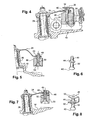
- the radial fingers 32 are engaged in cylindrical housings of the elements 20 of the control ring from the radially outer ends of these housings and are held in place by bent tabs 36 which bear on the radially outer ends of the fingers 32 and which are fixed by screws 38 on the elements 20 of the control ring. At their radially inner end, the fingers 32 bear against an internal shoulder of their cylindrical housing.
- the links 24 are secured to the radial pivots 26 of the variable-pitch vanes at one of their ends and comprise at their other end an orifice in which is engaged a ring 40 traversed by the associated radial finger 32, the inner surface of the ring 40 being flared from its middle portion towards its ends for a rotatably mounting of the rod 24 on the finger 32.
- the point of rotation of the rod is located at the contact of the middle part of the ring 40 with the radial finger 32.
- the finger 32 When the rod is connected to a bridge 22, the finger 32 extends radially outwardly relative to the rod and the arrangement is symmetrical to that shown in Figure 4 with respect to the link, but the point of rotation of the rod is always located in the contact area of the middle portion of the ring 40 with the radial finger 32 and is therefore at the same distance from the axis of rotation of the control ring 18.
- the radial finger 32 is fixed in an element 20 or a bridge 22 of the control ring by crimping a 42 of its ends and comprises in its middle part a flange 44 bearing on a shoulder of the element 20 or the bridge 22.
- the corresponding rod 24 is mounted by means of a ring 40 of the aforementioned type on the end portion 46 of the finger 32 opposite its flared end 42 of crimping.
- the assembly is substantially the same as that of FIGS. 5 and 6 and comprises an additional piece for retaining the link 24 on the end portion 46 of the radial finger 32, this piece retaining 48 being for example formed of a U-shaped sheet metal and having a flange 50 pierced with an engagement hole on the end 46 of the radial finger 32 and another parallel flange 52 which comprises a finger passage opening 32 and which is intended to be applied on the flange 44 of this finger, this flange being thus between the two flanges 50 and 52 of the part 48.
- this piece retaining 48 being for example formed of a U-shaped sheet metal and having a flange 50 pierced with an engagement hole on the end 46 of the radial finger 32 and another parallel flange 52 which comprises a finger passage opening 32 and which is intended to be applied on the flange 44 of this finger, this flange being thus between the two flanges 50 and 52 of the part 48.
- the part 48 is open, the finger 32 is engaged in the orifice of the wing 52, then is placed in its cylindrical housing of the control ring 18 and is crimped at its end 42, after what the ring 40 of the rod 24 is engaged on the end portion 46 of the finger 32 and the flange 50 is folded to be substantially parallel to the wing 52, the end of the radial finger 32 engaging in the orifice corresponding to the wing 50.
- FIGS. 5 to 8 have the advantage of being lighter than the embodiment of FIG. 4, the weight gain being for example of the order of 0.72 kg for the embodiment of FIG. Figure 5 and 0.65 kg for that of Figure 7, for each row of variable-pitch blades.
- An advantage of the invention is that the rods 24 of a row of variable pitch vanes are identical and angularly move the vanes of the same angle for a given rotation of the control ring, that these rods are connected to the semicircular elements or the bridges of the ring.
Landscapes
- Engineering & Computer Science (AREA)
- Mechanical Engineering (AREA)
- General Engineering & Computer Science (AREA)
- Structures Of Non-Positive Displacement Pumps (AREA)
- Control Of Turbines (AREA)
Claims (6)
- Steuervorrichtung für Schaufeln mit verstellbarer Anstellung in einem Turbotriebwerk wobei diese Schaufeln radial verlaufende Drehzapfen (26) aufweisen, die in Lagem eines Gehäuses (10) eingebaut und durch Stangen (24) mit einem Steuerring (18) verbunden sind, der sich außen um das Gehäuse (10) herum erstreckt, wobei dieser Ring zwei im Wesentlichen halbkreisförmige Elemente (20) umfasst, die an ihren Enden starr miteinander verbunden sind, und zwar durch Stege (22), die rittlings auf Längsflanschen (14) des Gehäuses angeordnet sind,
dadurch gekennzeichnet,
dass die Stangen (24) drehbar an Enden von radial verlaufenden Fingern (32) angebracht sind, welche an den halbkreisförmigen Elementen (20) und an den Stegen (22) des Steuerrings (18) sitzen, und dass die von den halbkreisförmigen Elementen (20) getragenen Finger (32) sich radial außerhalb dieser Elemente erstrecken, und die von den Stegen (22) getragenen Finger (32) sich radial innerhalb dieser Stege (22) erstrecken, so dass die Drehpunkte der Stangen (24) an diesen Fingern (32) sich in einem und demselben Abstand von der Drehachse des Steuerrings (18) befinden, und zwar was die von den halbkreisförmigen Elementen (20) getragenen, radial verlaufenden Finger (32) und die von den Stegen (22) des Steuerrings getragenen Finger (32) betrifft. - Vorrichtung nach Anspruch 1,
dadurch gekennzeichnet,
dass die Stangen (24) drehbar an den radial verlaufenden Fingern (32) angebracht sind. - Vorrichtung nach Anspruch 1 oder 2,
dadurch gekennzeichnet,
dass die radial verlaufenden Finger (32) in radial verlaufenden zylinderförmigen Aufnahmen der halbkreisförmigen Elemente (20) und der Stege (22) angebracht sind und dort durch umgebogene Laschen (36) festgehalten werden, die mit Schrauben (38) an diesen Elementen (20) und Stegen (22) befestigt sind und mit den Enden der Finger (32) zusammenwirken, an denen die Stangen (24) angebracht sind. - Vorrichtung nach einem der vorherigen Ansprüche,
dadurch gekennzeichnet,
dass die oben genannten radial verlaufenden Finger (32) mit ihren von den Stangen ab gewandten Enden (42) durch Quetschverbindung in zylinderförmigen Aufnahmen der halbkreisförmigen Elemente (20) und der Stege (22) des Steuerrings angebracht sind. - Vorrichtung nach Anspruch 4,
dadurch gekennzeichnet,
dass Haltemittel (48) für die Stangen (24) an den radial verlaufenden Fingern (32) angebracht sind. - Vorrichtung nach Anspruch 5,
dadurch gekennzeichnet,
dass die Haltemittel (48) U-förmige Werkstücke umfassen, deren Schenkel (50, 52) Durchlassöffnungen für die radial verlaufenden Finger (32) aufweisen und sich beiderseits eines Bundes (44) der radial verlaufenden Finger (32) befinden.
Applications Claiming Priority (2)
| Application Number | Priority Date | Filing Date | Title |
|---|---|---|---|
| FR0304735 | 2003-04-16 | ||
| FR0304735A FR2853930B1 (fr) | 2003-04-16 | 2003-04-16 | Dispositif de commande d'aubes a calage variable dans une turbomachine |
Publications (2)
| Publication Number | Publication Date |
|---|---|
| EP1469166A1 EP1469166A1 (de) | 2004-10-20 |
| EP1469166B1 true EP1469166B1 (de) | 2006-08-23 |
Family
ID=32893371
Family Applications (1)
| Application Number | Title | Priority Date | Filing Date |
|---|---|---|---|
| EP04291011A Expired - Lifetime EP1469166B1 (de) | 2003-04-16 | 2004-04-15 | Antriebsvorrichtung für verstellbare Leitschaufeln einer Turbomaschine |
Country Status (9)
| Country | Link |
|---|---|
| US (1) | US7004723B2 (de) |
| EP (1) | EP1469166B1 (de) |
| JP (1) | JP4113513B2 (de) |
| CA (1) | CA2463186C (de) |
| DE (1) | DE602004002020T2 (de) |
| ES (1) | ES2270303T3 (de) |
| FR (1) | FR2853930B1 (de) |
| RU (1) | RU2312225C2 (de) |
| UA (1) | UA80949C2 (de) |
Cited By (1)
| Publication number | Priority date | Publication date | Assignee | Title |
|---|---|---|---|---|
| US8061973B2 (en) | 2008-07-14 | 2011-11-22 | General Electric Company | Turbomachine including an adaptable intake system and method of controlling airflow to a turbomachine |
Families Citing this family (18)
| Publication number | Priority date | Publication date | Assignee | Title |
|---|---|---|---|---|
| FR2877059B1 (fr) * | 2004-10-27 | 2007-02-02 | Snecma Moteurs Sa | Biellette de commande destinee a l'entrainement d'une aube a calage variable |
| FR2879687B1 (fr) * | 2004-12-16 | 2007-04-20 | Snecma Moteurs Sa | Turbomachine a stator comportant un etage d'aubes de redresseur actionnees par une couronne rotative deplacee par des moyens moteurs electriques |
| FR2882570B1 (fr) * | 2005-02-25 | 2007-04-13 | Snecma Moteurs Sa | Dipositif de commande d'aubes a calage variable dans une turbomachine |
| US7207352B2 (en) * | 2005-05-02 | 2007-04-24 | United Technologies Corporation | Bushing for thermally independent bypass air metering valve |
| FR2896012B1 (fr) * | 2006-01-06 | 2008-04-04 | Snecma Sa | Dispositif anti-usure pour pivot de guidage d'aube a angle de calage variable de compresseur de turbomachine |
| JP5256977B2 (ja) * | 2008-10-03 | 2013-08-07 | 株式会社Ihi | ターボチャージャ |
| US8794910B2 (en) * | 2011-02-01 | 2014-08-05 | United Technologies Corporation | Gas turbine engine synchronizing ring bumper |
| WO2015050607A2 (en) * | 2013-07-08 | 2015-04-09 | United Technologies Corporation | Variable vane actuation system |
| RU2551773C1 (ru) * | 2014-02-12 | 2015-05-27 | Открытое акционерное общество "Уфимское моторостроительное производственное объединение" ОАО "УМПО" | Способ регулирования авиационного турбореактивного двигателя |
| US9644491B2 (en) | 2014-06-13 | 2017-05-09 | Pratt & Whitney Canada Corp. | Single bolting flange arrangement for variable guide vane connection |
| US9982686B2 (en) * | 2015-11-04 | 2018-05-29 | General Electric Company | Turnbuckle dampening links |
| FR3053383B1 (fr) * | 2016-07-04 | 2019-08-02 | Safran Aircraft Engines | Clinquant de retention de douilles d'anneaux de commande d'aubes a calage variable et turboreacteur l'incorporant |
| US10753224B2 (en) * | 2017-04-27 | 2020-08-25 | General Electric Company | Variable stator vane actuator overload indicating bushing |
| US10815818B2 (en) * | 2017-07-18 | 2020-10-27 | Raytheon Technologies Corporation | Variable-pitch vane assembly |
| GB201711582D0 (en) * | 2017-07-19 | 2017-08-30 | Rolls Royce Plc | Unison ring assembly |
| US10724543B2 (en) * | 2017-08-11 | 2020-07-28 | Raytheon Technologies Corporation | Bridge bracket for variable-pitch vane system |
| US11346240B2 (en) * | 2019-06-07 | 2022-05-31 | Raytheon Technologies Corporation | Gas turbine engine bleed valve damping guide link |
| US20210254557A1 (en) * | 2020-02-13 | 2021-08-19 | Honeywell International Inc. | Variable vane system for turbomachine with linkage having tapered receiving aperture for unison ring pin |
Family Cites Families (9)
| Publication number | Priority date | Publication date | Assignee | Title |
|---|---|---|---|---|
| US2305311A (en) * | 1937-07-07 | 1942-12-15 | Jendrassik George | Gas turbine plant equipped with regulating apparatus |
| BE496713A (de) * | 1949-07-01 | |||
| US3502260A (en) * | 1967-09-22 | 1970-03-24 | Gen Electric | Stator vane linkage for axial flow compressors |
| US3685920A (en) * | 1971-02-01 | 1972-08-22 | Gen Electric | Actuation ring for variable geometry compressors or gas turbine engines |
| DE2810240C2 (de) * | 1978-03-09 | 1985-09-26 | MTU Motoren- und Turbinen-Union München GmbH, 8000 München | Verstelleitgitter für axial durchströmte Turbinen, insbesondere Hochdruckturbinen von Gasturbinentriebwerken |
| FR2608678B1 (fr) * | 1986-12-17 | 1991-02-08 | Snecma | Dispositif de commande d'aubes a calage variable de redresseur de turbomachine |
| RU2117826C1 (ru) * | 1995-03-27 | 1998-08-20 | Акционерное общество открытого типа "А.Люлька-Сатурн" | Статор компрессора газотурбинного двигателя |
| US5601401A (en) * | 1995-12-21 | 1997-02-11 | United Technologies Corporation | Variable stage vane actuating apparatus |
| US5941537A (en) * | 1997-09-05 | 1999-08-24 | General Eletric Company | Pressure actuated static seal |
-
2003
- 2003-04-16 FR FR0304735A patent/FR2853930B1/fr not_active Expired - Fee Related
-
2004
- 2004-04-08 JP JP2004113876A patent/JP4113513B2/ja not_active Expired - Lifetime
- 2004-04-14 CA CA2463186A patent/CA2463186C/fr not_active Expired - Lifetime
- 2004-04-15 DE DE602004002020T patent/DE602004002020T2/de not_active Expired - Lifetime
- 2004-04-15 ES ES04291011T patent/ES2270303T3/es not_active Expired - Lifetime
- 2004-04-15 UA UA20040402731A patent/UA80949C2/uk unknown
- 2004-04-15 EP EP04291011A patent/EP1469166B1/de not_active Expired - Lifetime
- 2004-04-15 RU RU2004111592/06A patent/RU2312225C2/ru active
- 2004-04-16 US US10/825,306 patent/US7004723B2/en not_active Expired - Lifetime
Cited By (1)
| Publication number | Priority date | Publication date | Assignee | Title |
|---|---|---|---|---|
| US8061973B2 (en) | 2008-07-14 | 2011-11-22 | General Electric Company | Turbomachine including an adaptable intake system and method of controlling airflow to a turbomachine |
Also Published As
| Publication number | Publication date |
|---|---|
| JP2004316651A (ja) | 2004-11-11 |
| FR2853930B1 (fr) | 2007-02-23 |
| DE602004002020T2 (de) | 2007-03-08 |
| RU2312225C2 (ru) | 2007-12-10 |
| RU2004111592A (ru) | 2005-10-10 |
| FR2853930A1 (fr) | 2004-10-22 |
| CA2463186A1 (fr) | 2004-10-16 |
| US7004723B2 (en) | 2006-02-28 |
| ES2270303T3 (es) | 2007-04-01 |
| JP4113513B2 (ja) | 2008-07-09 |
| DE602004002020D1 (de) | 2006-10-05 |
| US20040208742A1 (en) | 2004-10-21 |
| CA2463186C (fr) | 2011-09-20 |
| EP1469166A1 (de) | 2004-10-20 |
| UA80949C2 (uk) | 2007-11-26 |
Similar Documents
| Publication | Publication Date | Title |
|---|---|---|
| CA2463186C (fr) | Dispositif de commande d'aubes a calage variable dans une turbomachine | |
| EP3833861B1 (de) | Auspuffkonus mit flexibler befestigung | |
| EP3074609B1 (de) | Vorrichtung zur führung von synchronringschaufeln mit verstellbarem neigungswinkel eines turbinenmotors und verfahren zur montage solch einer vorrichtung | |
| CA2807913C (fr) | Procede d'accrochage de blindage sur carter de turbine et ensemble d'accrochage pour sa mise en oeuvre | |
| EP3066320B1 (de) | Turbinenmotor mit einem mittel zur absorption von belastungen aufgrund des schubs dieses motors | |
| EP1496208B1 (de) | Lagerung der Schwenkachsen von verstellbaren Leitschaufeln von Turbomaschinen | |
| EP3775498B1 (de) | Kühlvorrichtung für eine turbine eines turbinenmotors | |
| CA2641017A1 (fr) | Perfectionnement a un anneau de commande de calage des aubes fixes d'une turbomachine | |
| WO2019193267A1 (fr) | Dispositif de refroidissement pour une turbine d'une turbomachine | |
| EP3863928B1 (de) | Turbostrahltriebwerk mit mittel zur aufhängung des triebwerks | |
| EP3084141B1 (de) | Turbinenmotorverdichter, insbesondere eines flugzeug-turbomotors oder mantelstrom-triebwerks | |
| FR3062876A1 (fr) | Compresseur haute pression pour turbomachine | |
| FR2652859A1 (fr) | Dispositif d'amortissement des vibrations de volet de tuyere et joint pivotant pour l'amortissement de vibrations. | |
| EP3863929A1 (de) | Aufhängungsanordnung für ein turbinentriebwerk | |
| EP4022175B1 (de) | Verstellhebel für eine variable verstelleinrichtung einer turbomaschine | |
| EP1548233B1 (de) | Befestigungsvorrichtung für Statorschaufel, sowie Leitschaufelstufe eines Verdichters mit einer solchen Vorrichtung | |
| EP3728039B1 (de) | Aufhängevorrichtung | |
| FR3059364A1 (fr) | Systeme de suspension d'un premier element annulaire dans un deuxieme element annulaire de turbomachine et turbomachine correspondante | |
| WO2018002480A1 (fr) | Ensemble de fixation d'un distributeur a un element de structure d'une turbomachine | |
| FR3041714A1 (fr) | Compresseur de turbomachine, en particulier de turbopropulseur ou de turboreacteur d'avion | |
| EP1674707B1 (de) | Düse mit veränderlichem Querschnitt mit einstückiger Steuerhebelhalterung für eine Turbomaschine | |
| FR3064671A1 (fr) | Bras de liaison d'une turbomachine muni d'un element de retenue de cale |
Legal Events
| Date | Code | Title | Description |
|---|---|---|---|
| PUAI | Public reference made under article 153(3) epc to a published international application that has entered the european phase |
Free format text: ORIGINAL CODE: 0009012 |
|
| AK | Designated contracting states |
Kind code of ref document: A1 Designated state(s): AT BE BG CH CY CZ DE DK EE ES FI FR GB GR HU IE IT LI LU MC NL PL PT RO SE SI SK TR |
|
| AX | Request for extension of the european patent |
Extension state: AL HR LT LV MK |
|
| RIN1 | Information on inventor provided before grant (corrected) |
Inventor name: RAULIN, DOMINIQUE Inventor name: BOURON, ALAIN Inventor name: MAROIS, FABRICE Inventor name: CHATEL, ALAIN |
|
| 17P | Request for examination filed |
Effective date: 20041223 |
|
| AKX | Designation fees paid |
Designated state(s): DE ES FR GB IT SE |
|
| RAP1 | Party data changed (applicant data changed or rights of an application transferred) |
Owner name: SNECMA |
|
| GRAP | Despatch of communication of intention to grant a patent |
Free format text: ORIGINAL CODE: EPIDOSNIGR1 |
|
| GRAS | Grant fee paid |
Free format text: ORIGINAL CODE: EPIDOSNIGR3 |
|
| GRAA | (expected) grant |
Free format text: ORIGINAL CODE: 0009210 |
|
| AK | Designated contracting states |
Kind code of ref document: B1 Designated state(s): DE ES FR GB IT SE |
|
| PG25 | Lapsed in a contracting state [announced via postgrant information from national office to epo] |
Ref country code: IT Free format text: LAPSE BECAUSE OF FAILURE TO SUBMIT A TRANSLATION OF THE DESCRIPTION OR TO PAY THE FEE WITHIN THE PRESCRIBED TIME-LIMIT;WARNING: LAPSES OF ITALIAN PATENTS WITH EFFECTIVE DATE BEFORE 2007 MAY HAVE OCCURRED AT ANY TIME BEFORE 2007. THE CORRECT EFFECTIVE DATE MAY BE DIFFERENT FROM THE ONE RECORDED. Effective date: 20060823 |
|
| REG | Reference to a national code |
Ref country code: GB Ref legal event code: FG4D Free format text: NOT ENGLISH |
|
| REF | Corresponds to: |
Ref document number: 602004002020 Country of ref document: DE Date of ref document: 20061005 Kind code of ref document: P |
|
| GBT | Gb: translation of ep patent filed (gb section 77(6)(a)/1977) |
Effective date: 20060920 |
|
| REG | Reference to a national code |
Ref country code: SE Ref legal event code: TRGR |
|
| REG | Reference to a national code |
Ref country code: ES Ref legal event code: FG2A Ref document number: 2270303 Country of ref document: ES Kind code of ref document: T3 |
|
| PLBE | No opposition filed within time limit |
Free format text: ORIGINAL CODE: 0009261 |
|
| STAA | Information on the status of an ep patent application or granted ep patent |
Free format text: STATUS: NO OPPOSITION FILED WITHIN TIME LIMIT |
|
| 26N | No opposition filed |
Effective date: 20070524 |
|
| PGRI | Patent reinstated in contracting state [announced from national office to epo] |
Ref country code: IT Effective date: 20080601 |
|
| PGFP | Annual fee paid to national office [announced via postgrant information from national office to epo] |
Ref country code: ES Payment date: 20120410 Year of fee payment: 9 |
|
| REG | Reference to a national code |
Ref country code: ES Ref legal event code: FD2A Effective date: 20140609 |
|
| PG25 | Lapsed in a contracting state [announced via postgrant information from national office to epo] |
Ref country code: ES Free format text: LAPSE BECAUSE OF NON-PAYMENT OF DUE FEES Effective date: 20130416 |
|
| REG | Reference to a national code |
Ref country code: FR Ref legal event code: PLFP Year of fee payment: 13 |
|
| REG | Reference to a national code |
Ref country code: FR Ref legal event code: PLFP Year of fee payment: 14 |
|
| REG | Reference to a national code |
Ref country code: FR Ref legal event code: CD Owner name: SAFRAN AIRCRAFT ENGINES Effective date: 20170717 |
|
| REG | Reference to a national code |
Ref country code: FR Ref legal event code: PLFP Year of fee payment: 15 |
|
| PGFP | Annual fee paid to national office [announced via postgrant information from national office to epo] |
Ref country code: FR Payment date: 20230321 Year of fee payment: 20 |
|
| PGFP | Annual fee paid to national office [announced via postgrant information from national office to epo] |
Ref country code: SE Payment date: 20230327 Year of fee payment: 20 Ref country code: IT Payment date: 20230322 Year of fee payment: 20 Ref country code: GB Payment date: 20230321 Year of fee payment: 20 |
|
| PGFP | Annual fee paid to national office [announced via postgrant information from national office to epo] |
Ref country code: DE Payment date: 20230321 Year of fee payment: 20 |
|
| REG | Reference to a national code |
Ref country code: DE Ref legal event code: R071 Ref document number: 602004002020 Country of ref document: DE |
|
| REG | Reference to a national code |
Ref country code: GB Ref legal event code: PE20 Expiry date: 20240414 |
|
| REG | Reference to a national code |
Ref country code: SE Ref legal event code: EUG |
|
| PG25 | Lapsed in a contracting state [announced via postgrant information from national office to epo] |
Ref country code: GB Free format text: LAPSE BECAUSE OF EXPIRATION OF PROTECTION Effective date: 20240414 |
|
| PG25 | Lapsed in a contracting state [announced via postgrant information from national office to epo] |
Ref country code: GB Free format text: LAPSE BECAUSE OF EXPIRATION OF PROTECTION Effective date: 20240414 |